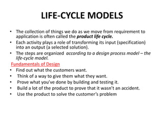
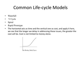
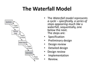
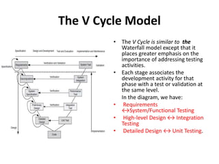
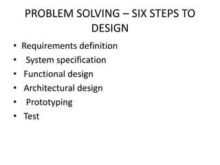
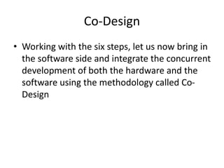
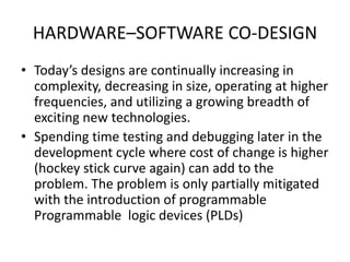
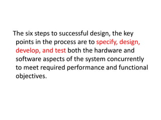
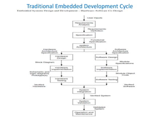
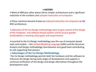
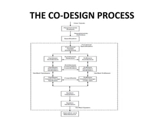
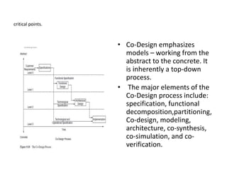
Embedded Systems Design and
Development
• .
LIFE-CYCLE MODELS
• The collection of things we do as we move from requirement to
application is often called the product life cycle.
• Each activity plays a role of transforming its input (specification)
into an output (a selected solution).
• The steps are organized according to a design process model – the
life-cycle model.
Fundamentals of Design
• Find out what the customers want.
• Think of a way to give them what they want.
• Prove what you’ve done by building and testing it.
• Build a lot of the product to prove that it wasn’t an accident.
• Use the product to solve the customer’s problem
Common Life-cycle Models
• Waterfall
• V Cycle
• Spiral
• Rapid Prototype
• The horizontal axis as time and the vertical one as cost, and apply it here,
we see that the longer we delay in addressing those issues, the greater the
cost will be. Cost is not limited to money alone.
The Waterfall Model
• The Waterfall model represents
a cycle – specifically, a series of
steps appearing much like a
waterfall, sequentially, one
below the next.
The steps are:
• Specification
• Preliminary design
• Design review
• Detailed design
• Design review
• Implementation
• Review.
• Successive steps are linked like a chain. Such a linking
tends to say: Complete this phase and go on to the next
• Observe that each phase is also connected to the
previous phase. That reverse connection provides an
essential verification link backwards to ensure that the
solution (in its current form)
• With the Waterfall model, the recognition of problems
can be delayed until later stages of development where
the cost of repair is higher (the hockey stick curve).
• The Waterfall model is limited in the sense that it does
not consider the typically iterative nature of real-world
design.
The V Cycle Model
• The V Cycle is similar to the
Waterfall model except that it
places greater emphasis on the
importance of addressing testing
activities.
• Each stage associates the
development activity for that
phase with a test or validation at
the same level.
In the diagram, we have:
• Requirements
↔System/Functional Testing
• High-level Design ↔ Integration
Testing
• Detailed Design ↔ Unit Testing.
• The specification and design procedure utilizes a
top-down model, whereas implementation and
test proceed from a bottom-up model.
• It is evident that each development activity builds
a more detailed model of the system and that
each verification step tests a more complete
implementation of the system
• The development concludes the design and
design-related test portion of the development
cycle of the system with both a verification and a
validation test against the original specification.
The Spiral Model
• A Spiral Model of Software
Development and
Enhancement
• The model takes a risk-
oriented view of the
development life cycle. Each
spiral addresses the major
risks that have been
identified.
• After all the risks have been
addressed, the Spiral model
terminates, as did the
Waterfall and V models, in
the release of a product.
• The Spiral model begins
with good specification of
the requirements.
• It then iteratively
completes a little of each
phase. Its philosophy is to
start small, explore the
risks, develop a plan to
deal with the risks, and
commit to an approach
for the next iteration.
Rapid Prototyping model
• The Rapid Prototyping model is intended to
provide a rapid implementation (hence the name)
of high-level portions of both the software and
the hardware early in the project.
• The model approach allows developers to
construct working portions of the hardware and
software in incremental stages.
• Each stage consists of design, code and unit test,
integration test, and delivery.
• The prototype is useful for both the designer and the
customer. For the designer, it enables the early
development of major pieces of the intended
functionality of system
• The prototype can be either evolutionary or
throwaway. It has the advantage of having a working
system early in the development process.
• As noted, problems can be identified earlier, and it
provides tangible measures of progress.
• To be effective, however, the rapid prototyping
approach requires careful planning at both the project
management and designer levels.
PROBLEM SOLVING – SIX STEPS TO
DESIGN
• Requirements definition
• System specification
• Functional design
• Architectural design
• Prototyping
• Test
Co-Design
• Working with the six steps, let us now bring in
the software side and integrate the concurrent
development of both the hardware and the
software using the methodology called Co-
Design
HARDWARE–SOFTWARE CO-DESIGN
• Today’s designs are continually increasing in
complexity, decreasing in size, operating at higher
frequencies, and utilizing a growing breadth of
exciting new technologies.
• Spending time testing and debugging later in the
development cycle where cost of change is higher
(hockey stick curve again) can add to the
problem. The problem is only partially mitigated
with the introduction of programmable
Programmable logic devices (PLDs)
The six steps to successful design, the key
points in the process are to specify, design,
develop, and test both the hardware and
software aspects of the system concurrently
to meet required performance and functional
objectives.
Traditional Embedded Systems
Development
Traditional Embedded Development Cycle
HISTORY
Work at IBM plus other places led to simpler architectures and a significant
reduction in the numbers and complex instruction set computers
These machines became known as reduced instruction set computers or the
RISC architecture.
objectives of the Co-Design methodology were to gain control of the design
of the hardware- and software-based systems and to ensure greater
predictability in meeting initial goals and requirements
essential to the Co-Design methodology was the use of computer-based
tools and models. – the Unified Modeling Language (UML) and the Structure
Analysis and Design methodology have become very good tools contributing
to and supporting that process
Advantages of the Co-Design Methodology
The Co-Design methodology permits both the hardware and the software to
influence the design during early stages of development and supports a
continual verification of the design and design alternatives throughout the
development cycle
THE CO-DESIGN PROCESS
• The design and development
of any serious large-scale
systems, we must consider
both the system to be
designed and the environment
in which it must operate.
• As our design progresses, we
decompose the top-level
system block into modules and
subsystems.
• Some of those modules will be
hardware, some software, and
some in a middle area that
may be combinations of both
• Components that must or
should be either hardware or
software are generally clear.
• We can say: this part must be
hardware or this part must be
software.
• For example, the power
supply, display,
communications port are
necessarily hardware.
• We can agree that the
operating system and
associated communications
drivers are necessarily
software.
• We have a gray area between the hardware
and software where the implementation
approach not precisely defined.
• Co-Design focuses on this area; those
components that may be either hardware,
software, or both.
• In such cases, we are making engineering
decisions or trade-offs related to speed, cost,
size, weight, or other factors.
critical points.
• Co-Design emphasizes
models – working from the
abstract to the concrete. It
is inherently a top-down
process.
• The major elements of the
Co-Design process include:
specification, functional
decomposition,partitioning,
Co-design, modeling,
architecture, co-synthesis,
co-simulation, and co-
verification.
SYSTEM REQUIREMENTS VERSUS SYSTEM DESIGN
SPECIFICATIONS
• Requirements: Give a description of something
wanted or needed. They are a set of needed
properties.
• requirements come from the marketing, product
planning, or sales department, and they
represent the customer’s needs
• Specification: is a description of some entity that
has or implements those properties
• System Design Specification is generated by
engineering as an answer to and a description of
how to implement the requirements
• The System Design Specification may require that an intersystem communication
channel transfer data at the rate of 10 000 bytes per second at a specific bit error
rate
A specification document should be:
• Complete
• Consistent
• Comprehensible
• Traceable to the requirements
• Unambiguous
• Modifiable
• Able to be written
Ece engineering embedded ppt -unit 2.pptx

Ece engineering embedded ppt -unit 2.pptx

  • 1.
    Embedded Systems Designand Development • .
  • 2.
    LIFE-CYCLE MODELS • Thecollection of things we do as we move from requirement to application is often called the product life cycle. • Each activity plays a role of transforming its input (specification) into an output (a selected solution). • The steps are organized according to a design process model – the life-cycle model. Fundamentals of Design • Find out what the customers want. • Think of a way to give them what they want. • Prove what you’ve done by building and testing it. • Build a lot of the product to prove that it wasn’t an accident. • Use the product to solve the customer’s problem
  • 3.
    Common Life-cycle Models •Waterfall • V Cycle • Spiral • Rapid Prototype • The horizontal axis as time and the vertical one as cost, and apply it here, we see that the longer we delay in addressing those issues, the greater the cost will be. Cost is not limited to money alone.
  • 4.
    The Waterfall Model •The Waterfall model represents a cycle – specifically, a series of steps appearing much like a waterfall, sequentially, one below the next. The steps are: • Specification • Preliminary design • Design review • Detailed design • Design review • Implementation • Review.
  • 5.
    • Successive stepsare linked like a chain. Such a linking tends to say: Complete this phase and go on to the next • Observe that each phase is also connected to the previous phase. That reverse connection provides an essential verification link backwards to ensure that the solution (in its current form) • With the Waterfall model, the recognition of problems can be delayed until later stages of development where the cost of repair is higher (the hockey stick curve). • The Waterfall model is limited in the sense that it does not consider the typically iterative nature of real-world design.
  • 6.
    The V CycleModel • The V Cycle is similar to the Waterfall model except that it places greater emphasis on the importance of addressing testing activities. • Each stage associates the development activity for that phase with a test or validation at the same level. In the diagram, we have: • Requirements ↔System/Functional Testing • High-level Design ↔ Integration Testing • Detailed Design ↔ Unit Testing.
  • 7.
    • The specificationand design procedure utilizes a top-down model, whereas implementation and test proceed from a bottom-up model. • It is evident that each development activity builds a more detailed model of the system and that each verification step tests a more complete implementation of the system • The development concludes the design and design-related test portion of the development cycle of the system with both a verification and a validation test against the original specification.
  • 8.
    The Spiral Model •A Spiral Model of Software Development and Enhancement • The model takes a risk- oriented view of the development life cycle. Each spiral addresses the major risks that have been identified. • After all the risks have been addressed, the Spiral model terminates, as did the Waterfall and V models, in the release of a product.
  • 9.
    • The Spiralmodel begins with good specification of the requirements. • It then iteratively completes a little of each phase. Its philosophy is to start small, explore the risks, develop a plan to deal with the risks, and commit to an approach for the next iteration.
  • 10.
    Rapid Prototyping model •The Rapid Prototyping model is intended to provide a rapid implementation (hence the name) of high-level portions of both the software and the hardware early in the project. • The model approach allows developers to construct working portions of the hardware and software in incremental stages. • Each stage consists of design, code and unit test, integration test, and delivery.
  • 11.
    • The prototypeis useful for both the designer and the customer. For the designer, it enables the early development of major pieces of the intended functionality of system • The prototype can be either evolutionary or throwaway. It has the advantage of having a working system early in the development process. • As noted, problems can be identified earlier, and it provides tangible measures of progress. • To be effective, however, the rapid prototyping approach requires careful planning at both the project management and designer levels.
  • 12.
    PROBLEM SOLVING –SIX STEPS TO DESIGN • Requirements definition • System specification • Functional design • Architectural design • Prototyping • Test
  • 13.
    Co-Design • Working withthe six steps, let us now bring in the software side and integrate the concurrent development of both the hardware and the software using the methodology called Co- Design
  • 14.
    HARDWARE–SOFTWARE CO-DESIGN • Today’sdesigns are continually increasing in complexity, decreasing in size, operating at higher frequencies, and utilizing a growing breadth of exciting new technologies. • Spending time testing and debugging later in the development cycle where cost of change is higher (hockey stick curve again) can add to the problem. The problem is only partially mitigated with the introduction of programmable Programmable logic devices (PLDs)
  • 15.
    The six stepsto successful design, the key points in the process are to specify, design, develop, and test both the hardware and software aspects of the system concurrently to meet required performance and functional objectives.
  • 16.
  • 17.
  • 18.
    HISTORY Work at IBMplus other places led to simpler architectures and a significant reduction in the numbers and complex instruction set computers These machines became known as reduced instruction set computers or the RISC architecture. objectives of the Co-Design methodology were to gain control of the design of the hardware- and software-based systems and to ensure greater predictability in meeting initial goals and requirements essential to the Co-Design methodology was the use of computer-based tools and models. – the Unified Modeling Language (UML) and the Structure Analysis and Design methodology have become very good tools contributing to and supporting that process Advantages of the Co-Design Methodology The Co-Design methodology permits both the hardware and the software to influence the design during early stages of development and supports a continual verification of the design and design alternatives throughout the development cycle
  • 19.
    THE CO-DESIGN PROCESS THECO-DESIGN PROCESS
  • 21.
    • The designand development of any serious large-scale systems, we must consider both the system to be designed and the environment in which it must operate. • As our design progresses, we decompose the top-level system block into modules and subsystems. • Some of those modules will be hardware, some software, and some in a middle area that may be combinations of both
  • 22.
    • Components thatmust or should be either hardware or software are generally clear. • We can say: this part must be hardware or this part must be software. • For example, the power supply, display, communications port are necessarily hardware. • We can agree that the operating system and associated communications drivers are necessarily software.
  • 23.
    • We havea gray area between the hardware and software where the implementation approach not precisely defined. • Co-Design focuses on this area; those components that may be either hardware, software, or both. • In such cases, we are making engineering decisions or trade-offs related to speed, cost, size, weight, or other factors.
  • 24.
    critical points. • Co-Designemphasizes models – working from the abstract to the concrete. It is inherently a top-down process. • The major elements of the Co-Design process include: specification, functional decomposition,partitioning, Co-design, modeling, architecture, co-synthesis, co-simulation, and co- verification.
  • 25.
    SYSTEM REQUIREMENTS VERSUSSYSTEM DESIGN SPECIFICATIONS • Requirements: Give a description of something wanted or needed. They are a set of needed properties. • requirements come from the marketing, product planning, or sales department, and they represent the customer’s needs • Specification: is a description of some entity that has or implements those properties • System Design Specification is generated by engineering as an answer to and a description of how to implement the requirements
  • 26.
    • The SystemDesign Specification may require that an intersystem communication channel transfer data at the rate of 10 000 bytes per second at a specific bit error rate A specification document should be: • Complete • Consistent • Comprehensible • Traceable to the requirements • Unambiguous • Modifiable • Able to be written