2. ii
ABSTRACT
Common sense dictates that as Internet connection speeds increase, so too does the bandwidth of
commonly transmitted data. Presumably, this means that today’s Internet of text and images will
evolve into an Internet with high-quality video conforming to the MPEG standard. This report
begins by introducing MPEG, the MPEG-2 standard, and providing a description of the structure
of an MPEG-2 video elementary stream. This is followed by a detailed examination of the
MPEG-2 picture encoding process. The fourth chapter extends the encoding procedure by devel-
oping and implementing an algorithm for transcoding pictures and video streams. Finally, pic-
tures from transcoded video are evaluated and it is demonstrated that they retain much of the
picture quality of the original high-bandwidth video encoding.
3. iii
ACKNOWLEDGEMENTS
I would like to thank Dr. Ken Ferens for the assistance and guidance he gave over the course of
this project. I would also like to acknowledge the contributions of Norsat International Inc., who
provided me with the MPEG-2 standards documents on which this thesis is based. I also had the
privilege of using their MPEG-2 video encoding hardware and software to produce the test bit
streams used in this report.
4. iv
CONTENTS
Abstract ......................................................................................................................................... ii
Acknowledgements...................................................................................................................iii
Contents....................................................................................................................................... iv
List of Figures ...............................................................................................................................v
List of Tables............................................................................................................................... vi
1 INTRODUCTION.................................................................................................................1
2 BACKGROUND TO MPEG-2 VIDEO..............................................................................3
2.1 OVERVIEW OF MPEG ........................................................................................................3
2.2 OVERVIEW OF MPEG-2.....................................................................................................4
2.3 STRUCTURE OF MPEG-2 VIDEO........................................................................................7
2.3.1 VIDEO SEQUENCES.....................................................................................................8
2.3.2 OTHER EXTENSIONS.................................................................................................11
2.3.3 GROUPS OF PICTURES ..............................................................................................13
2.3.4 PICTURES ..................................................................................................................14
3 MPEG-2 VIDEO ENCODING ..........................................................................................18
3.1 YCBCR COLOR SPACE .....................................................................................................18
3.2 PICTURE SLICES AND MACROBLOCKS ............................................................................19
3.2.1 MACROBLOCKS ........................................................................................................20
3.2.2 MACROBLOCK MOTION COMPENSATION..............................................................22
3.3 BLOCKS.............................................................................................................................23
3.3.1 DISCRETE COSINE TRANSFORM ..............................................................................24
3.3.2 QUANTIZATION .......................................................................................................25
3.3.3 SCANNING AND RUN-LENGTH ENCODING ...........................................................28
3.3.4 VARIABLE-LENGTH ENCODING..............................................................................29
4 MPEG-2 VIDEO TRANSCODING..................................................................................31
4.1 BACKGROUND TO MPEG-2 VIDEO TRANSCODING.......................................................31
4.2 MPEG-2 VIDEO TRANSCODER IMPLEMENTATION........................................................33
4.3 EXPERIMENTAL RESULTS AND ANALYSIS ......................................................................34
5 CONCLUSIONS AND RECOMMENDATIONS .........................................................40
Appendix: Transcoder source code.........................................................................................41
References ...................................................................................................................................63
Vita................................................................................................................................................64
5. v
LIST OF FIGURES
Figure 2-1: Overview of MPEG-2 Audio, Video, Systems Standards ................................5
Figure 2-2: PES packet syntax diagram ....................................................................................6
Figure 2-3: Transport stream syntax diagram .........................................................................7
Figure 2-4: Program Stream syntax diagram ...........................................................................7
Figure 2-5: MPEG-2 video start code ........................................................................................8
Figure 2-6: Sequence header syntax diagram..........................................................................9
Figure 2-7: Sequence extension syntax diagram...................................................................10
Figure 2-8: Sequence display extension syntax diagram....................................................11
Figure 2-9: Copyright extension syntax diagram .................................................................12
Figure 2-10: Quantization matrix extension syntax diagram .............................................12
Figure 2-11: User data syntax diagram ...................................................................................12
Figure 2-12: Group of pictures syntax diagram ....................................................................13
Figure 2-13: Picture header syntax diagram ..........................................................................14
Figure 2-14: Typical picture sequencing................................................................................15
Figure 2-15: Picture coding extension syntax diagram........................................................16
Figure 2-16: Picture display extension syntax diagram.......................................................17
Figure 3-1: Conversion between the RGB and YCbCr color spaces .................................19
Figure 3-2: Slices and Macroblocks ........................................................................................19
Figure 3-3: Slice syntax diagram..............................................................................................20
Figure 3-4: Macroblock syntax diagram.................................................................................21
Figure 3-5: Macroblocks and Blocks.......................................................................................24
Figure 3-6: Spatial domain and frequency domain blocks ................................................25
Figure 3-7: Default Quantization matrices for intra and non-intra blocks .....................26
Figure 3-8: Sample block quantization ..................................................................................27
Figure 3-9: Sample block zigzag scanning ............................................................................28
Figure 3-10: Sample block run-length encoding ..................................................................29
Figure 3-11: Variable-length encoding of sample block coefficients...............................30
Figure 4-1: Levels of Transcoding...........................................................................................32
Figure 4-2: Qualitative transcoding results (8 Mbps)..........................................................36
Figure 4-3: Qualitative transcoding results (2 Mbps)..........................................................38
6. vi
LIST OF TABLES
Table 3-1: Permitted Macroblock Types................................................................................22
Table 3-2: Interpretation of the quantiser_scale_code field...............................................27
Table 4-1: Quantitative transcoding results (8 Mbps).........................................................35
Table 4-2: Quantitative transcoding results (2 Mbps).........................................................37
7. 1
1 INTRODUCTION
Gordon Moore, founder of the microchip giant Intel Corporation, centered his business on a prin-
ciple he once enunciated. Moore’s law states that computer processing power doubles every
eighteen months while costs remain constant. This law is widely applicable to information tech-
nology-related issues, including bandwidth for data transmission.
The history of the Internet illustrates this well. When Internet access became widely available in
the early 1990’s, websites were primarily text. As the standard modem connection speed in-
creased beyond 14.4 kbps, pages were increasingly filled with images demanding these faster
connections. High-speed cable and digital subscriber line connections of the past few years rep-
resent the continuation of this trend, and the data of choice is now digitized audio, often in the
MP3 file format.
The next step up is digital video. Low-bandwidth (and thus low-quality) video web-casts are al-
ready available at many Internet media outlets, especially newsgathering organizations. Higher-
quality video service will likely become more common when mass-market satellite Internet ser-
vice becomes widespread. Two matters, however, need to be settled before video becomes as
much a part of the Internet as text and images. First, standards must be in place for compression
and distribution of digital video. Second, a balance must be reached between offering high-
quality broadband video and offering services compatible with an assortment of connection types
and speeds.
The Moving Pictures Experts Group (MPEG), formed in 1988 under the direction of the Interna-
tional Organization for Standardization (ISO), has mostly resolved the first issue. Their mandate
was to devise standards for the encoding and transmission of multimedia data (including audio
and video). The ensuing MPEG specifications have enjoyed a high degree of acceptance, exem-
plified by the popularity of the MP3 (MPEG-1|2 audio layer 3) audio file format and the MPEG-2
digital versatile disc (DVD).
The second issue, however, is not addressed by the MPEG specifications. There is an ongoing
search for a method of providing web-based video service compatible with a wide range of con-
nection speeds, short of offering segregated services for each class of connection.
The following report explains the MPEG-2 compression standard, specifically as it relates to digi-
tal video. This thesis also investigates a procedure for partially decoding and re-encoding
MPEG-2 video bit streams. This technique, known as transcoding, allows fundamental stream
8. 2
characteristics (e.g. bit rate) to be customized in the course of transmission. This could be used to
provide an efficient personalized video service capable of adapting to each client’s needs.
9. 3
2 BACKGROUND TO MPEG-2 VIDEO
The following sections provide background information to the MPEG standards, and a more spe-
cific overview of the MPEG-2 standard. This is followed by a detailed description of the struc-
ture of an MPEG-2 video bit stream.
2.1 OVERVIEW OF MPEG
The Moving Pictures Experts Group (MPEG) is a committee formed in 1988 to standardize the
storage of digital audio and video on compact discs. It operates under the joint direction of Inter-
national Organization for Standardization (ISO) and the International Electro-Technical Commis-
sion (IEC)1
.
MPEG released its first standard, MPEG-1: Coding of Moving Pictures and Associated Audio for
Digital Storage Media at up to about 1.5 Mbit/s, in 1993. At that time it consisted of three parts:
audio, video, and systems (combining the audio and video into a single stream). A fourth part
describing conformance testing of coded bit streams was subsequently released in 1995. There is
also a fifth part to the standard, offering a sample software implementation of a compatible en-
coder [3 128].
The MPEG-1 standard is directed towards the compact disc medium that has a single-speed data
rate of 1.2 Mbps. Bit streams typically contain audio sampled at 44.1 kHz and video sampled at
30 frames/second with a resolution of 360 by 240, which bears a close resemblance to North
American interlaced NTSC television pictures. MPEG-1 bit streams coded with these resolution
parameters and within the 1.2 Mbps bandwidth constraint have a video quality similar to con-
sumer VHS videotape. The standard is also crafted to allow for cost-effective hardware decoder
implementations that require only 512 KB of memory for the video buffer [4].
As technology progressed in the early 1990s, it became increasingly clear that the quality of
MPEG-1 constrained within those parameters was unsatisfactory. Even though the resolution of
MPEG-1 video could be scaled up to 4080×4080×60 fps (which would largely solve the quality
problem), MPEG-1 had difficulty encoding interlaced video, especially with motion vectors used
1
MPEG is actually a nickname. The official title for the group is ISO/IEC JTC1 SC29 WG11 (ISO/IEC
Joint Technical Committee 1, Sub-committee 29, working group 11).
10. 4
for compression. To address these shortcomings, MPEG released a new standard in 1995,
MPEG-2: Generic Coding of Moving Pictures and Associated Audio.
MPEG-2 bit streams usually fall within a range of bit rates between two and fifteen Mbps, which
is suitable for transmission via satellite or cable, or storage on Digital Versatile Discs (DVDs). It
contains several key improvements over MPEG-1, including support for both interlaced and pro-
gressive (non-interlaced) video formats, support for multi-channel surround sound and/or multi-
lingual sound (MPEG-1 only supports stereo audio), and provision for a wider range of audio
sampling frequencies [4]. A more thorough overview of MPEG-2 is given in §2.2.
Work also began on a third specification, MPEG-3, aimed at 20-40 Mbps High Definition Televi-
sion (HDTV) applications. By 1993, however, it became apparent that this standard would not be
completed in time for proposed launches of the technology. In addition, leading HDTV providers
determined that MPEG-2 would satisfactorily scale up for this application and committed to use it
rather than MPEG-3 – this lead to the quick demise of MPEG-3 [4].
MPEG remains active today, though it has broadened its focus beyond motion pictures. In Octo-
ber of 1998, MPEG-4: Very Low Bit Rate Audio-Visual Coding was released, providing a stan-
dard for multimedia applications (including specifications for low bit rate speech audio coding,
video, still images, and text). MPEG-7, entitled Multimedia Content Description Interface, is
scheduled for release in July 2001. Work on the latest standard, MPEG-21 Multimedia Frame-
work, began in June 2000 [3 130].
2.2 OVERVIEW OF MPEG-2
The MPEG-2 standard contains 10 parts, the first five of which are analogous to the MPEG-1
standard (systems, video, audio, conformance testing, and software implementation). The sixth
part, subtitled Digital Storage Media Command and Control (DSM-CC), provides a framework
for performing VCR-like functions on an MPEG bit stream (e.g. fast forward, pause). The re-
maining three parts describe a non-backwards compatible audio standard, higher-quality video
extension (subsequently withdrawn due to lack of interest), a real-time interface for set-top box
decoders, and conformance test requirements for DSM-CC (still under development) [3 128].
The following section gives a brief description of the structure of MPEG-2 systems, with techni-
cal details taken from the text of the standard [1].
11. 5
The MPEG-2 systems standard specifies two stream formats for combining audio, video, and
other data. First, it specifies the Transport Stream, which is appropriate for use in transmission
environments where data errors are likely. Transport streams often multiplex many individual
programs together, making it suitable for use in satellite or digital cable television applications.
Second, the MPEG-2 systems standard defines the Program Stream, which is designed for use
in data storage environments where bit errors are unlikely. Program Streams can carry only one
program with a common time base (which can have many elementary audio, video, or private
components), making it suitable for use in multimedia storage applications such as DVDs. The
MPEG-2 systems hierarchy is illustrated in Figure 2-1 [1 §0].
Video
Data
Left Audio
Data
Right Audio
Data
Video
Encoder
Audio
Encoder
Audio
Encoder
ES
Packetiser
ES
Packetiser
ES
Packetiser
ElementaryStreams
Packetised
ElementaryStreams
Program
Stream
Multiplexer
Transport
Stream
Multiplexer
Audio PES packets
Private Data PES
Video PES packets
2
nd
Program
•••
Other Programs
Program
Stream
Transport
Stream
MPEG-2 Video standard
(ISO/IEC 13818-2)
MPEG-2 Audio standard
(ISO/IEC 13818-3)
MPEG-2 Systems standard
(ISO/IEC 13818-1)
Figure 2-1: Overview of MPEG-2 Audio, Video, Systems Standards
At its lowest level, the MPEG-2 systems standard describes the process of transforming audio and
video elementary streams (as output from the MPEG-2 standard’s audio and video parts) into
Packetized Elementary Stream (PES) packets. PES packets normally do not exceed 64 kilo-
bytes in length, though the syntax allows for arbitrary length. All packets begin with a 4-byte
packet_start_code, which includes a 3-byte prefix of 0x000001 (hexadecimal) and a single-byte
stream_id ranging from 0xBC to 0xFF. This stream_id is used to distinguish between video and
audio channels of a single program (e.g. multilingual audio).
PES packet headers also contain 33-bit Decoding Time Stamp (DTS) and Presentation Time
Stamp (PTS) fields. These contain time values (with a resolution of 90 kHz) for when elementary
stream content should enter the decoder’s buffer, and be presented. The general structure of a
12. 6
PES packet is given in Figure 2-2. A more thorough discussion of packet structure can be found
in the MPEG specification [1 §2.4.3.7].
’10’
PES
scrambling
control
PES
priority
data
alignment
indicator
copyright
original
or
copy
7
flags
PES
header
data length
optional
fields
DTS ESCR
ES
rate
DSM
trick
mode
additional
copy info
previous
PES
CRC
PES
extensions
…
2 bits 2 1 1 1 1 8 8
33 42 22 8 7 16
PTS
33
start_code
prefix
’0x000001’
stream
id
PES
packet
length
optional
PES
header
PES packet data bytes
16824 bits
stuffing
bytes
’0xFF’
Figure 2-2: PES packet syntax diagram
MPEG-2 Transport Stream data is transmitted in 188-byte packets – the small packet size permits
rapid synchronization and error recovery. A Transport Stream packet consists of a required
header (4 bytes), an adaptation field (an optional extension to the header which does not exceed
26 bytes excluding private data), and a data payload (remainder of the 188 bytes). The payload
may contain multiplexed elementary, program, and/or transport streams.
Transport Stream packets begin with an 8-bit sync_byte field used for decoder synchronization
(the decoder must be able to locate the boundary between TS packets). The header of each
Transport Stream packet also contains a 13-bit packet identifier (PID), used to differentiate be-
tween different programs (analogous to television stations) in the Transport Stream. The adapta-
tion field contains a 42-bit program clock reference (PCR) indicating the intended arrival time,
with 27 MHz resolution, of the current packet to the decoder. The general structure of the Trans-
port Stream is shown in Figure 2-3 [1 §2.4.3].
13. 7
sync
byte
0x47
transport
error
indicator
payload
unit start
indicator
transport
priority
packet
identifier
(PID)
transport
scrambling
control
adaptation
field
control
continuity
counter
adaptation
field
discontinuity
indicator
random
access
indicator
ES
priority
indicator
5
flags PCR
original
PCR
adaptation
field
extension
8 bits 1 1 1 13 2 2 4
1 1 1 5 42 42
adaptation
field
length
8
TS
header
TS
payload
188 bytes
TS
header
TS
payload
188 bytes
TS
header
TS
payload • • •
splice
countdown
8
Transport
Stream
Figure 2-3: Transport stream syntax diagram
MPEG-2 Program Streams are divided into variable-length packs. All packs begin with a 14-
byte header that includes a 4-byte pack_start_code (0x000001BA) and a 42-bit system clock ref-
erence (SCR) analogous to the PCR of Transport Streams. A system header must follow the first
pack header of a Program Stream. It enumerates all elementary streams contained within the
Program Stream, indexed by stream_id. These headers are followed by pack data consisting of a
series of PES packets coming from any stream within the program. The general structure of a
Program Stream is shown in Figure 2-4 [1 §2.5.3].
pack
start
code
SCR
program
mux
rate
pack
stuffing
byte(s)
PES
packet
system
header
system
header
length
rate
bound
audio
bound
4
flags
video
bound
stream
id
32 bits 2 42 22 5
16 22 6 4 5 8
system
header
start code
8
pack
header pack
pack
header pack
pack
header pack• • •
ES
data
16
Program
Stream
PES
packet
PES
packet• • •
• • •
stream
id
8
ES
data
16
Elementary Stream enumeration
MPEG
program
end code
Figure 2-4: Program Stream syntax diagram
2.3 STRUCTURE OF MPEG-2 VIDEO
As stated earlier in §2.2, the MPEG-2 systems standard accepts audio and video elementary
streams as inputs to its specification. These elementary streams arise from the coding procedures
14. 8
defined in the audio and video parts of the MPEG-2 standard. The following section contains a
comprehensive structural description of a compliant video elementary stream, as defined in the
MPEG-2 video standard [2 §6].
All MPEG-2 bit streams contain recurring access points known as start codes. The specification
defines start codes as consisting of a prefix bit string of at least 23 ‘0’-bits followed by a single
‘1’-bit and an 8-byte start_code_value describing the nature of the data ahead. There should be
enough zero-bits in a start code so that the data immediately following it is byte-aligned.
Start codes provide a mechanism for searching through a coded bit stream without fully decoding
it (random access or “channel surfing”) and for re-synchronization in the presence of bit errors.
As hinted by the name, all MPEG-2 data structures begin with a start code, and they must never
be emulated within the body of an MPEG-2 data structure. The specification mandates that
marker ‘1’-bits appear in many structures to prevent this2
.
• • • • • • 000 00000000 00000000 00000001 x7x6x5x4x3x2x1x0 • • • • • • • •
start_code_prefix (24 bits)
start_code_value
(8 bits)
byte-aligning stuffing bits
Figure 2-5: MPEG-2 video start code
The following four sections provide an overview of the structure of MPEG-2 video. Video se-
quences, and the headers associated with them, are explained in §2.3.1. Several optional exten-
sions to the MPEG standard, which may apply to entire video sequences, are discussed in §2.3.2.
The chapter concludes with descriptions of elements underlying video sequences – groups of pic-
tures and pictures are discussed in §2.3.3 and §2.3.4.
2.3.1 VIDEO SEQUENCES
Sequence Header
The highest-level MPEG-2 video data structure is the autonomous video sequence. Video se-
quences are headed by a sequence_header [2 §6.3.3], identified with a start_code_value of 0xB3.
A typical MPEG-2 multimedia file contains one video sequence, though for random access pur-
2
An example of marker bits preventing start code emulation is found in the coding of 64-bit copyright
identifiers. Lest the identifier contain a string of 23 or more ‘0’ bits, the specification splits it into 22-bit
pieces, each separated by a marker ‘1’-bit.
15. 9
poses, the standard encourages encoders to repeatedly encode the sequence_header so they are
spaced through a bit stream every few seconds. A sequence_end_code (with start_code_value
0xB7) signals the end of a video sequence.
start code
prefix
’0x000001’
start code
value
’0xB3’
sequence
header
MPEG-2
video
sequence
Sequence End
start_code
’0x000001B7’
sequence
header
MPEG-2
video
sequence
sequence
header
MPEG-2
video
sequence
•••
frame
rate
code
aspect
ratio
information
vertical
size
value
horizontal
size
value
bit
rate
value
vbv
buffer
size value
optional
quantization
matrices
24 bits 8 12 12 4 4 18 1 10 8×64 each
3flags
3
usually 96 bits several megabytes usually 96 bits several megabytes usually 96 bits several megabytes 32 bits
MPEG-2 video sequence (§2.3.1)
Figure 2-6: Sequence header syntax diagram
As shown in Figure 2-6, the sequence_header contains parameters applicable to an entire video
sequence. The horizontal_size_value and vertical_size_value are unsigned integers indicating the
dimension of all pictures in the video sequence. The frame_rate_code specifies that the intended
(as opposed to the coded) video frame rate is one of the following values: 24, 25, 30, 50, or 60
fps3
. The 4-bit aspect_ratio_information code indicates that pictures in the video sequence have a
pre-defined aspect ratio of 4:3, 16:9, 2.21:1, or that the picture dimensions determine the aspect
ratio (meaning pixels are perfect squares).
The sequence header also contains a bit_rate_value field, which generally specifies the average
bit rate of an MPEG-2 bit stream in units of 400 bps. The vbv_buffer_size_value gives the size,
in two-kilobyte units, of the video buffering verifier (vbv). The concept of the video buffering
verifier is beyond the scope of this report – it relates to the memory buffer wherein just-decoded
pictures are stored during the decoding process. Finally, the sequence_header contains flags for
loading in user-defined 8×8 quantization matrices that override default values. This option is fur-
ther discussed in §2.3.2.
Sequence Extension
The MPEG-2 specification also defines structures known as extension headers, signified by a
start_code_value of 0xB5. A 4-bit extension_start_code_identifier, characterizing the nature of
3
The frame rate values 23.976, 29.97, and 59.94 ( 1001
24000 , 1001
30000
, and 1001
60000
) are also included for compatibil-
ity with various film digitizing processes.
16. 10
the data in the extension header, immediately follows the start code. The MPEG-1 specification
uses the same start code and header system as that used in MPEG-2. All fields introduced in
MPEG-2 to support new functionality lie within MPEG-2 extension headers and outside the tradi-
tional MPEG-1 headers.
The MPEG-1 sequence_header, as described above, inadequately characterizes newer MPEG-2
video sequences. An MPEG-2 sequence_extension header [2 §6.3.5], signified by an exten-
sion_start_code_identifier of ‘0001’, follows each MPEG-1 sequence_header in an MPEG-2 bit
stream. The layout of a sequence_extension header is shown in Figure 2-7.
extension
start code
‘0x000001B5’
sequence
header
MPEG-2
video
sequence
Sequence End
start_code
’0x000001B7’
sequence
header
MPEG-2
video
sequence
sequence
extension •••
prog-
ressive
seq.
vert.
size
ext.
horiz.
size
ext.
bit
rate
ext.
vbv
buffer
size ext.
32 bits 2 21 128 8
usually 96 bits several megabytes80 bits usually 96 bits several megabytes 32 bits
MPEG-2 video sequence (§2.3.1)
sequence
extension
80 bits
sequence
ext. ID
’0001’
4
chroma
format
2 1
frame rate
extension
21
n d
5
Figure 2-7: Sequence extension syntax diagram
The MPEG-2 standard extends the capabilities of MPEG-1 by supporting the encoding of pictures
as a pair of interlaced fields, rather than a non-interlaced picture frame. The progressive_-
sequence flag should be set to ‘1’ if and only if the video sequence consists entirely of progres-
sive (non-interlaced) pictures. The chroma_format field is a 2-bit code specifying the format of
chrominance sampling (4:2:0, 4:2:2, and 4:4:4 are supported) – the chrominance/luminance color
space is defined in §3.1.
The MPEG-2 sequence_extension header also contains fields that allow sequence_header pa-
rameters to exceed limits set out in the MPEG-1 standard. The two 2-bit horizontal/vertical size -
extensions, the 12-bit bit_rate_extension, and the 8-bit vbv_buffer_size_extension fields are
inserted in front of the most significant bits of their corresponding sequence_header parameters.
For example, these extend the maximum possible picture dimension from 4095 pixels (MPEG-1)
to 16 383 pixels (MPEG-2). Finally, the 2-bit frame_rate_extension_n and 5-bit frame_rate_-
extension_d fields broaden the frame rate values possible with MPEG-1 by performing the multi-
plication shown in equation (2.1) on the frame_rate_value decoded from frame_rate_code in the
sequence header:
17. 11
+
+
⋅=
dextensionrateframe
nextensionrateframe
valuerateframerateframe
___1
___1
___ (2.1)
Sequence Display Extension
The sequence_display_extension header [2 §6.3.6], as shown in Figure 2-8, indicated by an ex-
tension_start_code_identifier of ‘0010’, is a header that can optionally follow each sequence_-
extension. It specifies supplementary information about the target video display device –
MPEG-2 compliant decoders can ignore and discard information in this header. Within the ex-
tension header, the 3-bit video_format code indicates the display type from which the video se-
quence was originally encoded (e.g. PAL, NTSC, SECAM). This is followed by three optional
8-bit codes describing color space characteristics of the video source. The header concludes with
two 14-bit integers, display_horizontal_size and display_vertical_size, which specify the size of
the intended display’s active region in pixels. A display size smaller than that of the video picture
(horizontal_size_value×vertical_size_value) indicates that only a portion of the picture should be
on-screen. Conversely, a larger size indicates that the video should be displayed only on a por-
tion of the active region.
extension
start code
‘0x000001B5’
seq.
header
MPEG-2
video sequence
data
seq.
end
code
seq.
header
MPEG-2
video sequence
data
seq.
ext. •••
video
format
display
horizontal
size
colour
desc.
data
display
vertical
size
32 bits 3×8 143 14
96 bits several megabytes80 bits 96 bits several megabytes 32 bits
MPEG-2 video sequence (§2.3.1)
seq.
ext.
80 bits
sequence
ext. ID
’0010’
4
colour
desc.
flag
1 1
sequence
display
extension
usually 69 bits
sequence
display
extension
usually 69 bits
Figure 2-8: Sequence display extension syntax diagram
2.3.2 OTHER EXTENSIONS
Copyright Extension
The MPEG-2 specification mentions other optional extension headers applicable to an entire
video sequence. The copyright extension header, indicated by an extension_start_code_-
identifier of ‘0100’, is shown in Figure 2-9. Setting the copyright_flag to ‘1’ indicates that all
data following the present copyright_extension until the next copyright_extension is copyrighted.
The 8-bit copyright_identifier code identifies the copyright registration authority under which the
18. 12
work is registered, e.g. U.S. National Copyright Office. Finally, the 64-bit copyright_number is
the unique identifier assigned to the copyrighted work by the registration authority.
extension
start code
‘0x000001B5’
copyright
flag
copyright number
(64 bits)
original
or
copy
32 bits 11
copyright
ext. ID
’0100’
4
copyright
identifier
8 7 1 20 1 1 2222
Figure 2-9: Copyright extension syntax diagram
Quantization Matrix Extension
Each time a decoder processes a sequence_header, an MPEG-2 video decoder resets the quantiza-
tion matrices resident in its memory back to default values specified in the standard. The se-
quence_header may contain custom matrices replacing these default values, however, a quant_-
matrix_extension header may contain matrices overriding both the MPEG-2 defaults and those
in the sequence_header. The quant_matrix_extension extends the capability of the sequence_-
header (and that of MPEG-1) by allowing the bit stream to contain separate matrices for chromi-
nance and luminance color components.
extension
start code
‘0x000001B5’
32 bits
quantization
matrix
extension
identifier
’0010’
4
load
intra
quantizer
matrix
1
load
non-intra
quantizer
matrix
1
load
chroma
intra
quantizer
matrix
1
load
chroma
non-intra
quantizer
matrix
1
optional
matrix
8×64
optional
matrix
8×64
optional
matrix
8×64
optional
matrix
8×64
Figure 2-10: Quantization matrix extension syntax diagram
User Data Header
The user data header, identified by a start_code_value of 0xB2, is another regular MPEG-
1/MPEG-2 construct that can be used for extending the capabilities of the specification. This cre-
ates opportunities for text, such as closed-captioning or commentary data. In order for this pri-
vate information to be useful, both encoder and decoder must know the protocol behind it,
requiring conformance with an additional MPEG-compliant standard.
start code
prefix
‘0x000001’
private
user_data
24 bits n×8
user_data
start_code_value
’0xB2’
8
next
start code
‘0x000001’
24
••• •••
Figure 2-11: User data syntax diagram
Scalable Extensions
A final type of extension to MPEG-1 is the set of MPEG-2 scalable extensions. Scalability al-
lows video to be encoded in two separate layers: a base layer that can be decoded alone into
19. 13
meaningful video, and an enhancement layer containing picture data that improves the quality of
the base layer. One possible application of scalability would be to transmit the base layer along a
low-speed error-free channel and the enhancement over a less-reliable high-speed channel.
The sequence_scalable_extension header is used for partitioning a bit stream into these layers.
It contains a code describing the form(s) of the scalability employed, including spatial, signal-to-
noise ratio (SNR), and temporal scalability. Spatial scalability uses an enhancement layer to
enlarge the base layer picture size, SNR scalability uses an enhancement layer to improve the pic-
ture quality of the base layer, and temporal scalability adds extra pictures to the base layer in or-
der to increase the frame rate [2 §I.4.2].
2.3.3 GROUPS OF PICTURES
Video bit streams are generally divided into groups of pictures below the video sequence level, as
shown in Figure 2-12. Each group is preceded by a group_of_pictures_header [2 §6.3.8], indi-
cated by a start_code_value of 0xB8. The header contains a 25-bit time_code with hour, minute,
and second fields, which is used for tracking video sequence progress similar to time counters on
videocassette recorders. The header also contains flags indicating either that the group is
autonomous or that pictures within the group rely on pictures from a neighboring group.
start code
prefix
‘0x000001’
seq.
header
MPEG-2
video sequence
data
seq.
end
code
seq.
header
MPEG-2
video sequence
data
seq.
ext. •••
time_code
(25 bits)
broken
link
24 bits 11
96 bits several megabytes80 bits 96 bits several megabytes 32 bits
seq.
ext.
80 bits
group_of_pictures
start_code_value
’0xB8’
8
closed
gop
1
seq.
display
ext.
69 bits
seq.
display
ext.
69 bits
5
hrs
6
min
1 6
sec
6
pict
group of
pictures
header
59
MPEG-2
pictures
hundreds of kilobytes
group of
pictures
header
59
MPEG-2
pictures
hundreds of kilobytes
group of
pictures
header
59 bits
MPEG-2
pictures
hundreds of kilobytes
•••
MPEG-2 video sequence (§2.3.1)
§2.3.3
Figure 2-12: Group of pictures syntax diagram
The group_of_pictures_header is required by the MPEG-1 standard, however, it became optional
with MPEG-2 because its contents have no effect on the decoding process. Most MPEG-2 en-
coders, however, include it to improve bit stream organization.
20. 14
2.3.4 PICTURES
Picture Header
As the name suggests, groups of pictures consist of pictures. Each MPEG-2 picture is headed by
a picture_header structure [2 §6.3.9], shown in Figure 2-13, with start_code_value 0x00. The
10-bit temporal_reference integer is used as a picture counter, to be incremented for each encoded
picture (two interlaced fields count as a single picture), and reset to zero after each group_of_-
pictures_header. The vbv_delay field contains instantaneous bit rate information used by the
video buffering verifier.
start code
prefix
‘0x000001’
seq.
header
MPEG-2
video sequence
data
seq.
end
code
seq.
header
MPEG-2
video sequence
data
seq.
ext. •••
temporal
reference
vbv
delay
24 bits 16
96 bits several megabytes80 bits 96 bits several megabytes 32 bits
seq.
ext.
80 bits
picture
start_code_value
’0x00’
8
picture
coding
type
3
seq.
display
ext.
69 bits
seq.
display
ext.
69 bits
10
MPEG-2
picture
tens of kilobytes
•••
MPEG-2
picture
tens of kilobytes
picture
header
62/66/70
picture
header
62/66/70
bits
MPEG-2
picture
tens of kilobytes
picture
header
62/66/70
1 3 11 3
MPEG-2 video sequence (§2.3.1)
group of
pictures
header
59
MPEG-2
pictures
hundreds of kilobytes
group of
pictures
header
59
MPEG-2
pictures
hundreds of kilobytes
group of
pictures
header
59 bits
MPEG-2
pictures
hundreds of kilobytes
•••§2.3.3
§2.3.4
Figure 2-13: Picture header syntax diagram
The most important field in a picture_header is the 3-bit picture_coding_type code, used for clas-
sifying pictures as intra-coded (I), predictive-coded (P), or bi-directionally predictive-coded
(B)4
. I-pictures contain full picture information and are the least compressed type of picture –
they are similar to a JPEG image. P-pictures reduce the coding of redundant picture regions by
referencing sections of the previous I-picture or P-picture. B-pictures take this concept a step
further by referencing the previously displayed I- or P-picture and the next I- or P-picture to be
displayed.
4
The MPEG-1 specification also allowed for rarely-used DC-coded pictures (D-pictures), which consisted
of single-color blocks. They were not carried forward to the MPEG-2 standard. [4]
21. 15
A video bit stream should contain I-pictures often enough that predictive errors arising from P-
and B- pictures do not accumulate. By convention, most encoders make every twelfth picture an
I-picture; this means they occur every 0.4 seconds (30 Hz frame rate), adequate for random ac-
cess requirements. This leads to the common picture organization, shown Figure 2-14.
I0
B-1 B-2
P3
B1 B2
P6
B4 B5
P9
B7 B8
I12
B10 B11
I0 B1 B2
P3 B4 B5
P6 B7 B8
P9 B10 B11
References to previous pictures (Forward motion vectors)
• • •
• • •
Picture
encoding
sequence
Picture
display
sequence
Figure 2-14: Typical picture sequencing
Figure 2-14 also illustrates that the bit stream picture ordering is not the same as the display or-
der. B-pictures, which rely on past and future pictures, must be encoded after both reference pic-
tures.
Picture Coding Extension
The MPEG-2 standard appends a picture_coding_extension [2 §6.3.10], containing picture in-
formation not found in MPEG-1, after each MPEG-1 picture_header. The picture_coding_-
extension header is identified by an extension_start_code_identifier of ‘1000’ – its general
structure is shown in Figure 2-15.
22. 16
extension
start code
‘0x000001B5’
seq.
header
MPEG-2
video sequence
data
seq.
end
code
seq.
header
MPEG-2
video sequence
data
seq.
ext. •••
f_code[s][t]
32 bits
96 bits several megabytes80 bits 96 bits several megabytes 32 bits
seq.
ext.
80 bits
pict coding
ext. ID
’1000’
4
seq.
display
ext.
69 bits
seq.
display
ext.
69 bits
4
MPEG-2
picture
tens of kilobytes
•••
MPEG-2
picture
tens of kilobytes
picture
header
62/66/70
picture
header
62/66/70
bits
picture
coding
extension
66/86
3flags
3
picture
coding
extension
66/86
[0][0] [0][1] [1][0] [1][1]
4 44
intra
dc
precision
2
picture
structure
q
scale
type
intra
vlc
format
alter-
nate
scan
2 11 1
4flags
optional
4 20
MPEG-2 video sequence (§2.3.1)
group of
pictures
header
59
MPEG-2
pictures
hundreds of kilobytes
group of
pictures
header
59
MPEG-2
pictures
hundreds of kilobytes
group of
pictures
header
59 bits
MPEG-2
pictures
hundreds of kilobytes
•••§2.3.3
§2.3.4
Figure 2-15: Picture coding extension syntax diagram
The f_code fields are 4-bit integers used for determining motion vector precision (their role in P-
and B-picture references to previous/next pictures is summarized later in §3.2.2). The 2-bit pic-
ture_structure field code indicates that the current picture is encoded either as a full non-
interlaced picture or as the top or bottom field of an interlaced picture. The intra_dc_precision,
q_scale_type, intra_vlc_format, and alternate_scan flags control the image decoding method
(these fields are discussed in §3.3).
Picture Display Extension
An optional picture_display_extension [2 §6.3.12] may follow the picture_coding_extension
just as a sequence_display_extension optionally follows the sequence_extension. The picture_-
display_extension header contains a pair of 16-bit signed integers, frame_centre_horizontal_-
offset and frame_centre_vertical_offset, for each encoded picture or interlaced field following the
picture header. These two integers specify the intended offset between the center of the display’s
active region and the center of the displayed picture. The main application for this is clipping
irrelevant sidebar regions from 16:9 wide-screen pictures into the standard 4:3 format.
23. 17
extension
start code
‘0x000001B5’
seq.
header
MPEG-2
video sequence
data
seq.
end
code
seq.
header
MPEG-2
video sequence
data
seq.
ext. •••
frame centre
horizontal
offset
32 bits
96 bits several megabytes80 bits 96 bits several megabytes 32 bits
seq.
ext.
80 bits
pict display
ext. ID
’0111’
4
seq.
display
ext.
69 bits
seq.
display
ext.
69 bits
16
MPEG-2
picture
tens of kilobytes
•••
MPEG-2
picture
tens of kilobytes
picture
header
62/66/70
picture
header
62/66/70
bits
picture
coding
ext.
66/86
picture
coding
ext.
66/86
1
frame centre
horizontal
offset
16 1
•••
picture
display
extension
picture
display
extension
70/104/138 70/104/138
may appear 1, 2, or 3 times
MPEG-2 video sequence (§2.3.1)
group of
pictures
header
59
MPEG-2
pictures
hundreds of kilobytes
group of
pictures
header
59
MPEG-2
pictures
hundreds of kilobytes
group of
pictures
header
59 bits
MPEG-2
pictures
hundreds of kilobytes
•••§2.3.3
§2.3.4
Figure 2-16: Picture display extension syntax diagram
Summary
The preceding chapter provided a brief description of MPEG and MPEG-2, and a more thorough
overview of the structure of an MPEG-2 video bit stream. This included discussion of the head-
ers associated with video sequences, the highest syntactic structure in MPEG-2 video. Groups of
pictures and pictures (structures that lie beneath video sequences) were also explained in detail.
24. 18
3 MPEG-2 VIDEO ENCODING
The MPEG-2 video specification sets forth a standard for a bit stream, and defines a compatible
decoder as being a device capable of correctly processing this bit stream. There is no elaboration
on encoding techniques – they are left for private developers to invent. The following section,
adapted from §6.3.15 - §6.3.16 of the MPEG-2 video specification [2], describes the general pro-
cedure for compressing and encoding an image into an MPEG-2 picture.
3.1 YCBCR COLOR SPACE
The first stage in encoding an MPEG-2 picture is to convert the source image into the same color
space as the target MPEG-2 video sequence. As mentioned in §2.3.1, MPEG-2 uses television’s
luminance/chrominance (YCbCr) color space as opposed to the CRT display’s red/green/blue
(RGB) color space. Unless the sequence_display_extension specifies otherwise, the following
system of equations5
should be used for converting between the two color spaces:
.255,,,,,0
,12804025.03973.04375.0
1284375.03299.01006.0
1606168.0612.01818.0
≤≤
+−−=
++−−=
+++=
CrCbYBGRwhere
BGRCr
BGRCb
BGRY
(3.1)
Applying equations (3.1) to an RGB image yields a result in the YCbCr color space with chromi-
nance format 4:4:4. Because chrominance (Cr, Cb) data is less relevant to image integrity than
luminance (Y) data, most images undergo a further down-sampling of their chrominance compo-
nents into the 4:2:2 format for studio editing or the 4:2:0 format for mainstream consumer appli-
ances. As shown in Figure 3-1, an image containing nn× luminance samples contains nn× ,
nn
×2 , or 22
nn
× chrominance samples in the 4:4:4, 4:2:2, and 4:2:0 formats, respectively.
5
taken from ITU-R Recommendation ITU-R BT.709 (1990). [2 §6.3.6]
25. 19
140 160
159 171
104 162
163 164
167 200
200 199
115 152
157 160
153 111
146 144
141 129
125 130
115 152
157 160
149 127
133 129
115 152
157 160
138
131
R G B
Y
Cb
Cr
4:4:4 YCbCr
(12 bytes)
4:2:2 YCbCr
(8 bytes)
4:2:0 YCbCr
(6 bytes)
Figure 3-1: Conversion between the RGB and YCbCr color spaces
3.2 PICTURE SLICES AND MACROBLOCKS
Once a picture is in the proper color space, it can be divided into slices and macroblocks. The
MPEG-2 specification defines a macroblock as an image section consisting of a 16×16 matrix of
luminance samples and the corresponding chrominance data. A slice is defined as a series of
consecutive macroblocks, where macroblocks are ordered left-to-right and then top-to-bottom.
Figure 3-2 depicts an image divided into macroblocks and several slices.
macroblock
slices
16 pixels
Figure 3-2: Slices and Macroblocks
Picture slices are inserted into an MPEG-2 video elementary stream after their picture’s picture_-
header and picture_coding_extension structures. Slices are organized in a manner similar to other
headers in that they begin with a start code and contain some header information. The start_-
26. 20
code_value for a slice ranges between 0x01 and 0xAF, and indicates in which macroblock row of
the picture the slice begins. A 3-bit field, slice_vertical_position_extension, should appear after
the start_code_value for pictures with a height greater than 28006
. These bits should be inserted
as the most significant bits of an expanded macroblock row counter. Figure 3-3 shows the struc-
ture of a slice in the context of an MPEG-2 picture.
start code
prefix
‘0x000001’
slice_vertical
position_ext
(optional)
24
start_code_value
a.k.a.
slice_vertical_position
8 3
MPEG-2
picture
tens of kilobytes
•••
MPEG-2
picture
tens of kilobytes
picture
header
62/66/70
picture
header
62/66/70
picture
coding
extension
66/86
picture
coding
extension
66/86
quantiser
scale
code
5 1
picture
display
extension
picture
display
extension
70/104/138 70/104/138
series of
macroblocks
tens/hundreds of bytes
slice slice slice•••
several kilobytes several kilobytes several kilobytes
Figure 3-3: Slice syntax diagram
A picture slice also contains a 5-bit quantiser_scale_code integer. This important parameter is
used in a later stage of the encoding/decoding process and is thoroughly discussed in §3.3.2.
3.2.1 MACROBLOCKS
After the brief header information, an MPEG-2 picture slice contains a sequence of ordered mac-
roblocks. Macroblocks are not randomly accessible – picture slices are the lowest level MPEG-2
video structure using start code access points. In addition, macroblocks (and structures below
them) make frequent use of variable-length codes as a means of removing redundant bits from the
video bit stream. Higher-level header structures can afford the luxury of fixed-length fields, as
those headers represent a negligible percentage of bit stream bandwidth.
6
Note that 2800 = 16×0xAF, where 16 is the height of a macroblock
27. 21
start code
prefix
‘0x000001’
slice_vertical
position_ext
(optional)
24
start_code_value
a.k.a.
slice_vertical_position
8 3
quantiser
scale
code
5 1
series of
macroblocks
several kilobytes
macroblock macroblock macroblock•••
tens/hundreds of bytes tens/hundreds of bytes tens/hundreds of bytes
macroblock
address
increment
forward
motion
vector
variable-length code
usually several bits
macroblock
type
(5 flags)
variable-length
code (1-9 bits)
several bytes
quantiser
scale
code
5 bits
coded
block
pattern
variable-length coded
3-9 bits (4:2:0)
backward
motion
vector
several bytes
block
several bytes each
block
block
•••
0-6 blocks (4:2:0)
slice
macroblock_intra
macroblock_motion_forward
macroblock_motion_backward
macroblock_pattern
macroblock_quant
Figure 3-4: Macroblock syntax diagram
Macroblocks begin with the macroblock_address_increment variable-length code, which estab-
lishes the horizontal position of the macroblock (the slice start code establishes its vertical posi-
tion). The most common scenario, a macroblock_address_increment code of ‘1’, means that the
forthcoming macroblock lies immediately beside the previously coded macroblock. Longer vari-
able-length codes can be used to represent an arbitrary number of skipped macroblocks. When an
encoder chooses to skip over a macroblock in a picture, the bit stream’s eventual decoder displays
the macroblock from the previous picture with identical coordinates.
Macroblock Types
The next variable-length encoded field occurring in a macroblock is the crucial macroblock_type
code. It consists of five flags that specify which MPEG-2 video compression features are used
for the current macroblock. Having the macroblock_intra flag set signifies that the macroblock
is intra-coded (i.e. it makes no reference to other macroblocks from other pictures). If the macro-
block_motion_forward and/or macroblock_motion_backward flags are set, the macroblock
references a macroblock from another picture using motion vectors. The macroblock_pattern
flag is often used along with the macroblock_motion_forward/backward flags to code a correc-
tion to the macroblock resulting from the motion prediction.
Eligibility to use the various compression features incorporated in the macroblock_type code de-
pends on what type of picture (I, P, or B) the macroblock resides in. Intra-coded (I-) pictures are
required to contain a full image that can be decoded without reliance on neighboring pictures;
28. 22
macroblocks within an I-picture are prevented from using the macroblock_motion_-
forward/backward and macroblock_pattern flags. Similarly, macroblocks from P-pictures are
limited to unidirectional references to the previous P-picture’s macroblocks — they cannot use
the macroblock_motion_backward flag. All picture types are permitted to contain macroblocks
with the macroblock_intra flag, though intra macroblocks typically only appear as a last resort in
P- and B-pictures. Table 3-1 lists the possible combinations of macroblock_type flags with pic-
ture types – ‘ ’ denotes a “don’t-care” condition.
Table 3-1: Permitted Macroblock Types
macroblock_motion_forward
macroblock_motion_backward
macroblock_pattern
macroblock_intra
macroblock_quant
I-, P-, B-pictures
P-pictures
P-, B-pictures
P-, B-pictures
B-pictures
B-pictures
The fifth flag from the macroblock_type code is the macroblock_quant flag. It can be set when-
ever the macroblock_intra or macroblock_pattern flags are set. If the macroblock_quant flag is
set, a 5-bit integer, quantiser_scale_code, follows the macroblock_type variable-length code as
shown in Figure 3-4. This field has the identical function to the quantiser_scale_code found in a
picture slice header. In fact, when present, this quantiser_scale_code replaces the slice header
code’s value. The quantiser_scale_code integer is explained later in §3.3.2.
3.2.2 MACROBLOCK MOTION COMPENSATION
As many as two motion vectors may appear after the quantiser_scale_code field, depending on
the values of the macroblock_motion_forward/backward flags. The current macroblock can ref-
erence a similar macroblock in the previous and/or next I-/P-picture to conserve bandwidth by
avoiding fully intra-coding each macroblock. Motion vectors separately code their vertical and
horizontal components with differing precision, taking advantage of the fact that horizontal mo-
29. 23
tion tends to be more pronounced than vertical motion in typical video sequences. Each compo-
nent consists of a variable-length motion_code (biased in favor of spatially close macroblocks)
for roughly locating the referenced macroblock, and a motion_residual integer of f_code7
bits that
has a finer resolution of a half-pixel. In addition, these vectors are coded as an offset of the pre-
vious macroblock’s motion vector, reflecting the reality that clusters of macroblocks tend to move
in concert.
Macroblocks from B-pictures man contain forward-pointing motion vectors, backward-pointing
motion vectors, or both. In the latter case, where both the macroblock_motion_forward and mac-
roblock_motion_backward flags are set, the resulting macroblock should be an interpolation of
both predictions – this effectively smoothes video motion. Conversely, the ability to select which
direction (forwards or backwards) motion vectors should reference overcomes the problem of
momentary object occlusion in the picture. For a more thorough discussion of motion compensa-
tion techniques, consult §7.6 of the MPEG-2 video specification [2].
If the macroblock_pattern flag is set, the coded_block_pattern code appears next in a macroblock
as shown in Figure 3-4. Motion compensation techniques contain inaccuracies, and therefore
macroblocks cannot simply be lifted from one picture and directly pasted into another. The mo-
tion prediction error for a macroblock is encoded similar to an intra macroblock, with the excep-
tion that the coefficients are relative offsets from the prediction instead of absolute pixel values.
The coded_block_pattern variable-length code appears in the macroblock header if the macrob-
lock_pattern flag is set; it directs which macroblock sections (blocks) have those additional error
coefficients (offsets) coded. It should also be noted that this field may appear in P-pictures with-
out any motion compensation. In this case, it is assumed that no motion has taken place and the
predicted macroblock is taken from the previous picture at the same spatial coordinates.
3.3 BLOCKS
MPEG-2 video pictures are divided into slices comprised of 16×16 macroblocks. Beyond this,
the lowest-level syntactic structure used in MPEG-2 video is the block. Blocks result from mac-
roblocks being further divided along spatial and luminance/chrominance component lines into
8×8 matrices with 8-bit coefficients. They are encoded sequentially into the bit stream after mac-
roblock header information, motion vectors, and coded_block_pattern codes. Depending on the
7
f_code is an integer between one and nine coded into each picture_header. There are four separate f_code
fields for vertical/horizontal and forward/backward motion vectors.
30. 24
chroma_format (4:2:0, 4:2:2, or 4:4:4) of the video sequence, a macroblock may contain 6, 8, or
12 ordered blocks, respectively. The decomposition of macroblocks into blocks and the order
these blocks appear in the bit stream are shown in Figure 3-5.
1
st
2
nd
3
rd
4
th
6
th
10
th
8
th
12
th
5
th
9
th
7
th
11
th
1
st
2
nd
3
rd
4
th
6
th
8
th
5
th
7
th
1
st
2
nd
3
rd
4
th 6
th
5
th
chroma_format = 4:4:4
(12 blocks)
chroma_format = 4:2:2
(8 blocks)
chroma_format = 4:2:0
(6 blocks)
Cr CbY
Cr CbY
Cr CbY
Cb
Cr
Y
16×16 MACROBLOCK
8×8 BLOCKS
OR
OR
Figure 3-5: Macroblocks and Blocks
Intra-coded macroblocks should have all 6, 8, or 12 component blocks encoded in the bit stream
at the end of the macroblock structure. Non-intra macroblocks with coded prediction errors
(macroblock_pattern flag set) should encode these offsets into the block structure and then place
these at the end of the macroblock structure, as intra macroblocks do with their absolute pixel
values. As the coded_block_pattern field stipulates, blocks are usually missing from the encoded
sequence – these represent macroblock sections where the prediction error is insignificant.
Rather than inefficiently occupying 64 bytes each, blocks undergo a multi-stage compression
process while being inserted into the video bit stream. Removing redundant and irrelevant data
from blocks by this process can often reduce their size to just a few bytes each. The next sections
briefly describe the compression procedure (the reader is encouraged to consult §7.1 - §7.5 of the
MPEG-2 video specification [2] for a more thorough treatment).
3.3.1 DISCRETE COSINE TRANSFORM
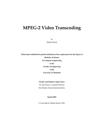
The first step in the compression of an 8×8 block containing raw pixel data is to perform a dis-
crete cosine transform on it. This turns an 8×8 block of 8-bit coefficients in the spatial domain
into an 8×8 block of 12-bit coefficients in the frequency domain. Equation (3.2), taken from An-
31. 25
nex A of the specification [2], performs a two-dimensional discrete cosine transform on a matrix
with spatial coordinates ( )yx, and frequency domain coordinates ( )vu, .
( ) ( ) ( ) ( ) ( )
( ) ( )
( )
( )
≠
=
==
⋅⋅⋅= ∑∑= =
++
0,1
0,
;7...,2,1,0,,,
coscos,,
2
1
7
0
7
0
16
12
16
12
4
1
n
n
nCyxvu
yxfvCuCvuF
x y
vyux ππ
(3.2)
increasingfrequency
1001-73 -18 -10 3 7 -6 -4
114181 -46 -55 -7 19 2 -10
13 -38 29 16 1 -3 -2 -8
-71 -35 31 37 -8 -10 7 4
-7 -21 7 23 -3 -4 -4 -9
10 -4 -6 5 3 -15 5 6
-1 -6 -9 4 1 1 0 -8
-10 -12 0 9 2 -4 1 7
141146138142130141128125
155167186183125110112116
138158189194149117117116
120138154162142127124124
89 86 89 98 118127134124
78 73 74 85 110130135136
76 68 68 73 129138151165
71 70 56 97 126156174180
Spatial domain coefficients Frequency domain coefficients
Discrete
cosine
transform
DC coefficient
increasing frequencyincreasing x-values
increasingy-values
Figure 3-6: Spatial domain and frequency domain blocks
Figure 3-6 shows the discrete cosine transform performed on a sample 8×8 spatial domain block.
The entire compression process will be performed on this sample block in the remaining sections
of this chapter.
3.3.2 QUANTIZATION
All 64 coefficients of a spatial domain picture block are of equal importance – this is not true for
the corresponding frequency domain block. The human eye has difficulty perceiving high fre-
quency image components in a similar way that the ear has difficulty detecting noise near and
above 20 kHz. The MPEG-2 video specification compresses pictures by removing irrelevant and
largely unnoticeable image data, so the higher-frequency block coefficients situated in the lower
right corner are obvious candidates for cutbacks. The frequency domain block coefficients in
Figure 3-6 are shown with text boldness proportional to their importance.
32. 26
The standard achieves this data reduction by quantizing coefficients, i.e. reducing their precision
by dividing them by large integers. The specification provides for a set of 8×8 quantization ma-
trices containing the integers by which each corresponding block coefficient is divided. The de-
fault matrices for intra and non-intra blocks are shown in Figure 3-7.
16 16 16 16 16 16 16 16
16 16 16 16 16 16 16 16
16 16 16 16 16 16 16 16
16 16 16 16 16 16 16 16
16 16 16 16 16 16 16 16
16 16 16 16 16 16 16 16
16 16 16 16 16 16 16 16
16 16 16 16 16 16 16 16
8 16 19 22 26 27 29 34
16 16 22 24 27 29 34 37
19 22 26 27 29 34 34 38
22 22 26 27 29 34 37 40
22 26 27 29 32 35 40 48
26 27 29 32 35 40 48 58
26 27 29 34 38 46 56 69
27 29 35 38 46 56 69 83
Intra-coded blocks
macroblock_intra = ‘1’
macroblock_pattern = ‘0’
Non-intra coded blocks
macroblock_intra = ‘0’
macroblock_pattern = ‘1’
Figure 3-7: Default Quantization matrices for intra and non-intra blocks
Intra blocks, which contain transformed absolute pixel values, are quantized to a much greater
degree (especially at high frequencies) than non-intra blocks, which contain small offsets correct-
ing motion vector block predictions. The quant_matrix_extension header, referred to in §2.3.2,
can be used to override the default values for these matrices. In addition, the extension header
allows the encoder to specify a separate pair of intra/non-intra matrices for chrominance and lu-
minance blocks if the 4:2:2 or 4:4:4 chrominance format is in use.
The MPEG-2 video standard also specifies a second stage of quantization, where all 64 coeffi-
cients are further divided by a scalar. The integer divisor, quantiser_scale, is determined by de-
coding the 5-bit quantiser_scale_code field found in the slice and macroblock headers according
to Table 3-2. The q_scale_type flag is located in the picture_coding_extension. The non-linear
step size associated with a set q_scale_type flag is supposedly an improvement over the linear
step size (q_scale_type = ‘0’) from MPEG-1.
33. 27
Table 3-2: Interpretation of the quantiser_scale_code field
quantiser_scale
quantiser_scale_code
q_scale_type=0q_scale_type=1
1 2 1
2 4 2
3 6 3
4 8 4
…
…
…
15 30 22
16 32 24
17 34 28
18 36 32
19 38 36
20 40 40
…
…
…
29 58 96
30 60 104
31 62 112
Figure 3-8 applies the quantization stage to the sample block from the previous section, assuming
quantiser_scale_code = 4. All coefficients are multiplied by 16 before the quantization step – this
preliminary correction is further discussed in §4.1. For example, in Figure 3-8 the DC coefficient
1001 is multiplied by 16 and divided by its quantization matrix coefficient (8) and quantiser_scale
(8), with a result of 250.
250 -9 -2 -1 0 1 0 0
14 23 -4 -5 -1 1 0 -1
1 -3 2 1 0 0 0 0
-6 -3 2 3 -1 -1 0 0
-1 -2 1 2 0 0 0 0
1 0 0 0 0 -1 0 0
0 0 -1 0 0 0 0 0
-1 -1 0 0 0 0 0 0
1001 -73 -18 -10 3 7 -6 -4
114181 -46 -55 -7 19 2 -10
13 -38 29 16 1 -3 -2 -8
-71 -35 31 37 -8 -10 7 4
-7 -32 7 23 -3 -4 -4 -9
10 -4 -6 5 3 -15 5 6
-1 -6 -9 4 1 1 0 -8
-10 -12 0 9 2 -4 1 7
Raw frequency coefficients Quantised frequency coefficients
Quantisation
( )( )( ) 25.2501001 88
16
=
Figure 3-8: Sample block quantization
34. 28
3.3.3 SCANNING AND RUN-LENGTH ENCODING
The quantization step removes data irrelevant to picture integrity from blocks. The scanning/run-
length encoding step re-arranges the quantized data in a format that reduces data redundancy in
the bit stream. The reader should notice that many higher-frequency coefficients in the block are
zero, and that most non-zero coefficients are concentrated near the DC coefficient in the upper-
left corner of the block. In preparation for run-length encoding, the 8×8 block should be scanned
into a 64-entry array in a zigzag fashion, as shown on the sample block in Figure 3-9. An alterna-
tive scanning order, activated when the alternate_scan flag in the picture_coding_extension is set,
was introduced to MPEG-2 to improve performance with interlaced video [4].
250 -9 -2 -1 0 1 0 0
14 23 -4 -5 -1 1 0 -1
1 -3 2 1 0 0 0 0
-6 -3 2 3 -1 -1 0 0
-1 -2 1 2 0 0 0 0
1 0 0 0 0 -1 0 0
0 0 -1 0 0 0 0 0
-1 -1 0 0 0 0 0 0
Quantised frequency coefficients Array of scanned coefficients
0 1 5 6 14 15 27 28
2 4 7 13 16 26 29 42
3 8 12 17 25 30 41 43
9 11 18 24 31 40 44 53
10 19 23 32 39 45 52 54
20 22 33 38 46 51 55 60
21 34 37 47 50 56 59 61
35 36 48 49 57 58 62 63
Regular
zigzag
scanning
250 -9 -2 -1 0 114 23 -4 -51 -3 2-6 -3-1
0 0-1 1 01 0 02 3 -1-2 11 00
-10 0-1 02 0 00 0 00 -1 0-1 -1
00 0-1 0 00 0 0 00 0 0 0 0 0
Figure 3-9: Sample block zigzag scanning
The block, which has now become a 64-entry array, should next be manipulated using a modified
run-length encoding algorithm transforming it into a series of integer pairs consisting of a run
component and a signed level component. The run integer represents the number of zero entries
preceding a level value in the array. The final run of zero entries in the array ends at the 64th
block entry and not with a signed level – this reality is encoded as End of Block. This syntax is
illustrated in Figure 3-10, which applies the algorithm to the scanned sample block.
35. 29
Array of scanned coefficients
Run-length encoded coefficients (run, level)
Run-length
encoding
0 0
-1
1 0
1
0 0
2
3 -1
-2
1
1
0
0
-10 0-12 00 00 -1-1 -1
0 0 0 0 00 0-1 0 00 0 0 00 0 0 0 0 0
0,14 0,1 0,-10,-9 0,230,250 0,-2 0,-4 0,-1 0,-3 1,10,-6 0,20,-3 0,-5 0,-1
0,-2 0,1 1,10,2 2,10,1 0,3 4,-1 0,-1 0,-1 8,-12,-1 2,-10,2 1,-1 End of
Block
250 -9 -2 -1 0 114 23 -4 -51 -3 2-6 -3-1
Figure 3-10: Sample block run-length encoding
3.3.4 VARIABLE-LENGTH ENCODING
The final stage of processing block data is to format the array run-length encoding into a bit se-
quence for insertion into the video bit stream. Certain combinations of run and level are statisti-
cally common, and table B-148
in the MPEG-2 video specification [2] assigns space-saving
variable-length codes for 113 of these combinations. Provision is made for encoding the other
261 000 statistically rare combinations – the bit string ‘000001’ is an escape code signaling that a
6-bit fixed-length run field and a 12-bit fixed length level field follow. The End of Block marker
is encoded with the shortest variable-length code of all: ‘10’.
The DC (top-left) coefficient of intra-coded blocks strongly echoes the general (or mean) color
level of the block. The MPEG-2 specification takes advantage of the fact that many pictures con-
tain relatively uniform color levels by not encoding the absolute DC value of a block. Instead,
the signed offset from the DC coefficient in the previously processed block (of the same lumi-
nance/chrominance channel) is encoded. Reflecting the importance of a precise DC coefficient
8
Table B-15 contains an alternate listing of variable-length codes, improved since MPEG-1, suitable for
intra-coded macroblocks. This table should be used if the picture_coding_extension flag intra_vlc_format
is set.
36. 30
offset, it is encoded outside the previously mentioned variable-length coding scheme, and treated
as an integer field with a length determined by a preceding variable-length code9
.
Figure 3-11 shows the MPEG-2 variable-length coding scheme applied to the sample block from
the previous sections. The sample block would now be ready for insertion into the MPEG-2
video elementary stream.
Run-length encoded coefficients (run, level)
0,14 0,1 0,-10,-9 0,230,250 0,-2 0,-4 0,-1 0,-3 1,10,-6 0,20,-3 0,-5 0,-1
0,-2 0,1 1,10,2 2,10,1 0,3 4,-1 0,-1 0,-1 8,-12,-1 2,-10,2 1,-1 End of
Block
Variable-length coded coefficients (for insertion into bit stream)
00000000110000 110 1110000000110001 00000000011000011111110011111010 01001 00001101
111 001011 0110001000011 01000001011 001001101 111 01001 110 011001000 01010110 001010
001101 111111 0000111101011 0101101000 0111 10
0x7F3E8062018600609E1A590F96826B7C84E514C6A17FADC3E
or
Variable-
length
coding
Figure 3-11: Variable-length encoding of sample block coefficients
Summary
The proceeding chapter described the procedure for encoding a picture into an MPEG-2 video bit
stream. The first step, conversion into the chrominance/luminance (YCbCr) color space, was
briefly considered. The decomposition of a picture into slices and macroblocks, along with mac-
roblock motion compensation techniques, was reviewed next. The chapter concluded with a de-
scription of the compression procedure for blocks – this algorithm was able to compress a high-
entropy 64-byte sample block into a bit stream occupying less than 25 bytes.
9
The 2-bit intra_dc_precision code found in the picture_coding_extension header refers to the precision of
the absolute DC value and not the offset DC value.
37. 31
4 MPEG-2 VIDEO TRANSCODING
The process of converting between different compression formats and/or further reducing the bit
rate of a previously compressed signal is known as transcoding. Transcoding involves partial
decoding of a compressed bit stream, but stops short of full decoding because, in the case of
video, there is no need to display the video to a user. It also involves partial re-encoding, though
processing power is conserved because transcoders re-use many first-generation encoder deci-
sions to produce second-generation bit streams [5].
Video transcoding has many real-world transmission applications. Servers of video bit streams,
when equipped with transcoding capabilities, could provide an arbitrary number of bit streams
with varying quality and bandwidth characteristics, all derived from a single premium video en-
coding. This would support clients with a range of connection qualities, or even be responsive to
a single client with a connection quality that varies over time. Alternatively, in a storage medium
environment, transcoding could be used to reduce video file size after encoding, possibly allow-
ing data to be ported from a high-capacity storage medium to another with a lower capacity.
The following sections describe the operation and implementation of an MPEG-2 video
transcoder, and provide analysis and quantitative results of a bit stream subjected to transcoding.
4.1 BACKGROUND TO MPEG-2 VIDEO TRANSCODING
Speed is a primary concern for video transcoding, as a video server making use of it must be ca-
pable of transcoding one or more bit streams into an assortment of second-generation bit streams,
all in real-time. There are three common levels of transcoding (see Figure 4-1), each offering a
different balance between output quality and computational complexity.
38. 32
§3.3.1
Discrete Cosine Transform
§2.3.4
Picture Type Decisions
(I, P, or B)
§3.3.4
Variable-length Coding
§3.3.3
Scanning and
Run-length Encoding
§3.3.2
Quantisation
§3.2.1
Motion Compensation
(macroblock_type decisions)
§3.2.2
Motion Compensation
(prediction error calculation)
decoding
encoding
decoding
encoding
decoding
encoding
Simple
Transcoder
Intermediate
Transcoder
Complex
Transcoder
Figure 4-1: Levels of Transcoding
The simplest transcoder partially decodes a video bit stream, parsing picture slices and macrob-
locks up to the variable-length encoded blocks as described in §3.3.4. The variable-length encod-
ing, run-length encoding/scanning (§3.3.3), and quantization (§3.3.2) are rolled back, stopping
short of performing an inverse discrete cosine transform on the 8×8 block. The block is then re-
quantized – this time with larger quantization divisors – and re-scanned, run-length encoded, and
variable-length encoded into a block bit string shorter than the original.
An intermediate transcoder goes further than the previous example for P- and B-pictures by per-
forming the inverse discrete cosine transform and re-calculating the motion vector’s prediction
error. This new prediction error would be with respect to the second-generation reference mac-
roblock as opposed to the first-generation macroblock [5]. The forward discrete cosine transform
is redone, and the bit stream is further re-constructed according to the same procedure as the sim-
ple transcoder.
The two previous transcoders retained the original video encoder’s decisions regarding picture
types, motion prediction, and coding decisions [5]. The most complex form of transcoding per-
forms almost a full decoding (stopping short of display-specific decoding, such as YCbCr-to-
RGB color space conversion), and re-encodes the bit stream with fewer I-pictures and more B-
pictures, increased reliance on motion vectors, and coding decisions with lower precision and
thresholds than before.
39. 33
Each step up in transcoding intensity entails a substantial increase in computational complexity.
The extra inverse/forward cosine transforms of the second option, and the additional motion pre-
diction decisions in the third option, tend to rule out the possibility of both from being imple-
mented as a software add-on to conventional real-time video servers. The software transcoder
implementation accompanying this report uses the superficial transcoding techniques of the first
option.
The treatment of MPEG-2 video block quantization in §3.3.2 neglected certain factors in the
quantization equations, particularly for non-intra blocks. Equations (4.1) and (4.2) contain the
forward and inverse quantization equations for intra blocks, respectively. Fq represents the quan-
tized 8×8 block of integers, F the unquantized block, and Q the current quantization matrix – u
and v are integer indices ranging from 0 to 7.
scalequantiseruvQ
uvF
uvFq
_]][[
]][[16
]][[
⋅
⋅
= (4.1)
16
_]][[]][[
]][[
scalequantiseruvQuvF
uvF
q ⋅⋅
= (4.2)
The forward and inverse quantization equations for non-intra blocks (4.3 and 4.4) introduce addi-
tional complexity by mixing the signum function with integer division. The inverse quantization
function is taken from §7.4.2.3 of the MPEG-2 video specification [2].
( )
32
_]][[])][[sgn(]][[2
]][[
scalequantiseruvQuvFuvF
uvF
qq ⋅⋅+⋅
= (4.3)
2
_]][[
]][[32
sgn
_]][[
]][[32
]][[
⋅
⋅
−
⋅
⋅
=
scalequantiseruvQ
uvF
scalequantiseruvQ
uvF
uvFq (4.4)
4.2 MPEG-2 VIDEO TRANSCODER IMPLEMENTATION
MPEG-2 transport streams were obtained by encoding analog video signals with iCompression’s
iVAC hardware MPEG-2 encoder. Video elementary streams (.M2V files) were extracted from
40. 34
the resulting .MPG transport stream files using tools from Microsoft’s DirectX Media 6.0 SDK.
Video elementary stream files could then be viewed with Windows Media Player software.
The sample MPEG-2 video transcoder was written with Microsoft Visual C++ 6.0, running on a
600 MHz Pentium III computer. The source code was based entirely on the text of the MPEG-2
video standard; it contains few optimizations10
and is thus quite readable. For a complete listing
of the source code, see the Appendix.
The sample transcoder implements the most superficial transcoder (see §4.1) for the Windows NT
operating system. The graphical user interface allows the user to select an input MPEG-2 video
elementary stream (.M2V) file and an output .M2V file with standard Windows NT dialog boxes.
The user can also input a small quantiser_scale_code_increment integer representing a uniform
increment of the quantiser_scale_code parameter in each slice and macroblock header. Upon
execution, the transcoder parses the input file and decodes it up to (and including) the inverse
quantization step. The file is then re-encoded with a new quantiser_scale_code, incremented to
strengthen the quantization, and saved as the output file.
4.3 EXPERIMENTAL RESULTS AND ANALYSIS
An uncompressed still image was captured and encoded into a 60-second MPEG-2 video elemen-
tary stream at a high bit rate of 8.00 Mbps. The resulting .MPG transport stream file was next
filtered into an .M2V video elementary stream file. This original elementary stream file was then
transcoded into several second-generation streams with a variety of quantiser_scale_code_-
increment parameters.
The first I-picture from each stream was extracted and saved as a Windows .BMP file. Lumi-
nance peak signal-to-noise ratios (PSNR) were calculated for each second-generation transcoded
bitmap. This measurement treated the I-picture from the first-generation video stream as the
original signal rather than the original still image, because the digital-to-analog-to-digital conver-
sion of the still image into the first-generation video changed image dimensions and caused color
brightness distortion. The quantitative results of this experiment are shown in Table 4-1. Figure
4-2 shows: (a) the original still image, (b) the I-picture from the first-generation encoding, (c-f)
and the I-pictures from the four transcoded videos.
10
The transcoder typically runs at one-fifth of real-time speed, though optimizations (particularly for fre-
quently-used variable-length decoding routines) could resolve this issue.
41. 35
Table 4-1: Quantitative transcoding results (8 Mbps)
quantiser_scale_-
code_increment
Average quan-
tiser_scale_code
Average quan-
tiser_scale
value
Average Bit Rate
Luminance
PSNR
0 (original) 3 6 8.00 Mbps —
1 4 8 6.78 Mbps 35.91 dB
2 5 10 3.88 Mbps 35.48 dB
4 7 14 3.12 Mbps 33.57 dB
transcoded
bitstreams
6 9 18 2.61 Mbps 32.93 dB
42. 36
(a) Original Still Image
(b) First-generation encoded video (8 Mbps)
(quantiser_scale_code_increment = 0)
(c) Transcoded video (6.78 Mbps)
(quantiser_scale_code_increment = 1)
(d) Transcoded video (3.88 Mbps)
(quantiser_scale_code_increment = 2)
(e) Transcoded video (3.12 Mbps)
(quantiser_scale_code_increment = 4)
(f) Transcoded video (2.61 Mbps)
(quantiser_scale_code_increment = 6)
Figure 4-2: Qualitative transcoding results (8 Mbps)
43. 37
As Table 4-1 indicates, transcoding degrades picture quality only slightly, according to the peak
signal-to-noise ratio measure. This observation is confirmed by inspection of the images in
Figure 4-2 – only the heavily compressed images (d-f) show signs of “blockiness” in facial areas.
There is also a barely-noticeable loss of detail in the feathers on the hat. Note that because each
video contained a still image displayed for 60 seconds, the I-pictures are representative of the en-
tire video.
The original 8 Mbps video could not be transcoded down any lower than the 2.61 Mbps reached
with quantiser_scale_code_increment = 6. Transcoding of any kind modifies the bit rate, which
in turn affects the operation of the video buffering verifier. During video playback, the bit stream
is routed through the video buffering verifier. This buffer must be kept in a delicate state where it
cannot overflow its capacity (as specified in the sequence header) and it can never be emptied.
Each picture_header contains a 16-bit vbv_delay field specifying a time (with 11 µs resolution) to
delay decoding the next picture. The sample transcoder implementation did not properly recalcu-
late this field, though efforts were made for it to do so. Therefore, whenever transcoded videos
were viewed, the media player would crash as soon as this buffer emptied.
For 8 Mbps video transcoded with quantiser_scale_code_increment greater than 6, the media
player would crash before any I-pictures could be decoded and viewed. To determine whether
the transcoding results apply to video streams with lower bit rates, the original still image was
encoded into a lower-bandwidth 2 Mbps video elementary stream, and the transcoding experi-
ment was repeated. The quantitative and qualitative results of this repeated experiment are shown
in Table 4-2 and Figure 4-3, which mirror the organization of Table 4-1 and Figure 4-2.
Table 4-2: Quantitative transcoding results (2 Mbps)
quantiser_scale_-
code_increment
Average quantiser_-
scale_code
Average quan-
tiser_scale value
Average Bit Rate
Luminance
PSNR
0 (original) 14 28 2.00 Mbps —
1 15 30 1.87 Mbps 36.15 dB
4 18 36 1.80 Mbps 36.00 dB
6 20 40 1.70 Mbps 35.16 dB
15 27 54 1.64 Mbps 31.98 dB
44. 38
(a) Original Still Image
(b) First-generation encoded video (2 Mbps)
(quantiser_scale_code_increment = 0)
(c) Transcoded video (1.87 Mbps)
(quantiser_scale_code_increment = 1)
(d) Transcoded video (1.80 Mbps)
(quantiser_scale_code_increment = 4)
(e) Transcoded video (1.70 Mbps)
(quantiser_scale_code_increment = 6)
(f) Transcoded video (1.64 Mbps)
(quantiser_scale_code_increment = 15)
Figure 4-3: Qualitative transcoding results (2 Mbps)
45. 39
The results in Table 4-2 and Figure 2-1 show that transcoding 2 Mbps video degrades quality
more so than with 8 Mbps video – picture (f) appears especially blocky. The bandwidth reduc-
tions are also less spectacular, possibly because encoded blocks (which are compressed with this
form of transcoding) account for a smaller proportion of the bandwidth. Overhead from bit
stream elements left untouched by the transcoding algorithm, such as headers and motion vectors,
accounts for a greater proportion of the bandwidth.
46. 40
5 CONCLUSIONS AND RECOMMENDATIONS
The preceding report presented descriptions of MPEG, the MPEG-2 standard, and the structure of
an MPEG-2 video elementary stream. This was followed by a detailed examination of the
MPEG-2 picture encoding process. An algorithm for transcoding MPEG-2 bit streams, for the
purpose of decreasing stream bandwidth, was then developed, implemented, and analyzed.
The transcoding results in §4.3 demonstrate that transcoding video bit streams can significantly
decrease the bandwidth of a bit stream at the expense of picture quality. The qualitative results
suggest that this is a price worth paying. The results are promising, but preliminary – the video
buffering verifier under-run problem needs to be resolved so transcoded videos can be examined
in their entirety. In this case, only the first I-picture of each video could be retrieved and ana-
lyzed before the buffer emptied and the media player crashed.
The results showed that superficial transcoding techniques, where only the block data is
transcoded, face natural compression limits. It appears as though video stream bandwidth cannot
be reduced by more than an order of magnitude with these techniques, because of the overhead of
standard headers and excess motion vectors. Using the alternative quantization scheme11
may
extend this range to some extent, but perhaps a more intrusive method of transcoding should be
considered, where relatively unimportant motion vectors are removed from the bit stream alto-
gether.
Transcoding could also be examined for video streams created by a variety of MPEG-2 encoders
at a wider range of bit rates. This would include software encoders, where an original still image
could be digitally inserted into a video stream without the distortion of digital-to-analog-to-digital
conversion. This would make a quantitative comparison between transcoded video and an origi-
nal image possible.
Finally, it should be acknowledged that the peak signal-to-noise ratio measure of image degrada-
tion is not the ultimate measure of image quality. Two images having few ‘close’ pixel values
may be poles apart according to a mathematical algorithm but virtually indistinguishable to the
human eye. The best judge of video quality will always be a subjective human observer, viewing
at full size and full frame rate.
11
For more information, see the description of the q_scale_flag in §3.3.2.