This document is a thesis presented to the Graduate School at the University of Missouri-Columbia by Shashi R. Shilarnav for the degree of Master of Science. The thesis examines solutions for transcoding a transport stream MPEG2 video from a VBrick system to lower bitrates suitable for streaming to a live audience. It discusses frameworks for transcoding the MPEG2 stream to formats like Windows Media Video, RealVideo, and H.264. It also describes developing a graphical user interface application to facilitate using the transcoding framework. The thesis compares different codecs for transcoding and analyzes the compression achieved and quality of the transcoded video streams.
![1
1 Introduction
1.1 Foreword
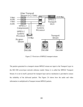
The use of video in teaching and learning is a common practice in education today. As learning
online becomes more of a common practice in education, streaming video and audio play a
bigger role in delivering course materials to online learners. There are several benefits of video
streaming of class room lectures. Classroom lectures can be delivered in real-time around the
network so that remote users can tune in from wherever they are. Lectures can also be recorded
and stored on a video-on-demand server for future viewing/playback.
The Nuclear Science and Engineering Institute [1] (NSEI) at University of Missouri –
Columbia has been using a VBrick 6200 [2] to facilitate distant learning through video
conferencing during a classroom session. VBrick 6200 is a device which can encode/decode
DVD quality MPEG2 [3] video in real time. It is also used as a MPEG2 streaming server and
client to send and receive MPEG2 video streams.
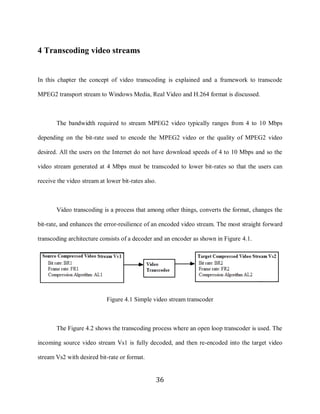
In this thesis the problems associated with streaming live video to a large audience is
considered. The multicast [4] protocol is being used to enable video conferencing between three
institutions, University of Missouri – Columbia, University of Missouri – Rolla and the
University of Missouri – Kansas City, participating in the distant learning program and the three
universities listed have connectivity to Internet2 [5] network.
The transmission of MPEG2 video between VBricks at 6 Mbps is made possible by the
use of state-of-the-art networking facilities provided by Internet2. Internet2 is the foremost
1](https://image.slidesharecdn.com/transcoding-transport-stream-mpeg21267/85/Transcoding-Transport-Stream-MPEG2-11-320.jpg)
![6
2.2 Compression
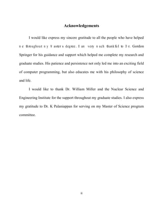
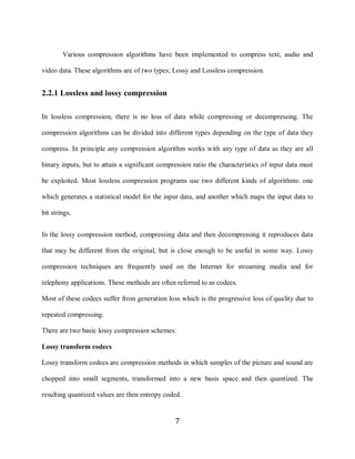
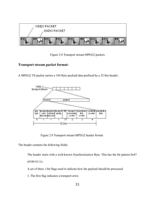
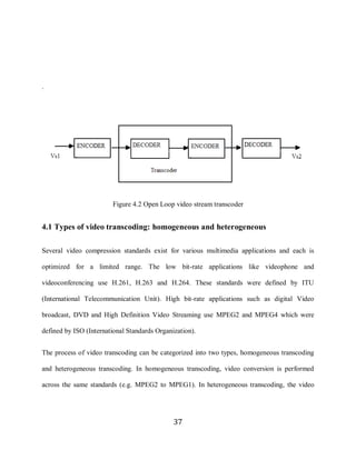
From the description of video in Section 2.1, the data rate of uncompressed video for a given
resolution (image size), bit depth and frame rate can be calculated and Table 2.1 shows the
amount of bandwidth required to stream uncompressed video over Internet.
Table 2.1 Data rate of uncompressed video
It is not always feasible to stream video at these bit rates as the amount of available
bandwidth is limited.
Several attempts have been made [6] to stream uncompressed video over the network. A
variation of the Access Grid Node [7] called the Ultra Grid Node [8] has been implemented to
demonstrate the capability of the IP network to stream uncompressed HD quality video. But the
amount of network bandwidth available to a typical user on the Internet is not enough to receive
uncompressed video. Hence raw video is compressed to various other formats using codec to be
able to stream over the Internet.
6](https://image.slidesharecdn.com/transcoding-transport-stream-mpeg21267/85/Transcoding-Transport-Stream-MPEG2-16-320.jpg)
![10
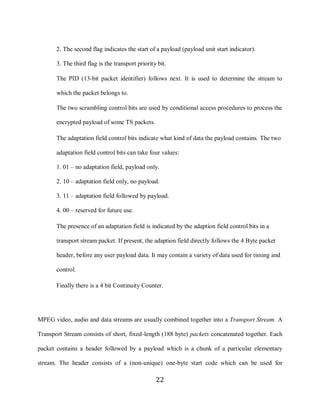
2.3 Video compression standards
A video codec is a device or software module that enables video compression or decompression
for digital video. Video codecs can be divided into two families; video compression standards
from International Telecommunications Union-Telecommunications (ITU-T) and the video
compression standards by International Organization for Standardization (ISO).
2.3.1 H.261, H.263 and H.264
ITU H.261 [9], was the first video compression standard that gained widespread acceptance for
videoconferencing over the Integrated Services Digital Network (ISDN). The ITU H.261
standard was designed to operate at p multiples of baseline ISDN data rate or p x 64 kb/s.
Another standardization effort with Public Switched Telephone Network (PSTN) as primary goal
was initiated by ITU-T in 1993 where the data rate was multiples of 33.6 kb/s. This was called
the H.263 [10] codec. An enhanced version of H.263 has now been finalized and is called the
H.264/AVC [11].
2.3.2 MPEG
ISO established Motion Pictures Expert Group [12], as a standard for compressing moving
pictures (video) and associated audio on a CD-ROM. MPEG1 was the resulting standard which
achieves approximately VHS quality video and audio at about 1.5 Mb/s. An extension of work
on MPEG1 for applications toward digital television and higher bit rates is called MPEG2.
MPEG4 provides improved compression efficiency and error resilience features and increased
functionality including object-based encoding.
10](https://image.slidesharecdn.com/transcoding-transport-stream-mpeg21267/85/Transcoding-Transport-Stream-MPEG2-20-320.jpg)
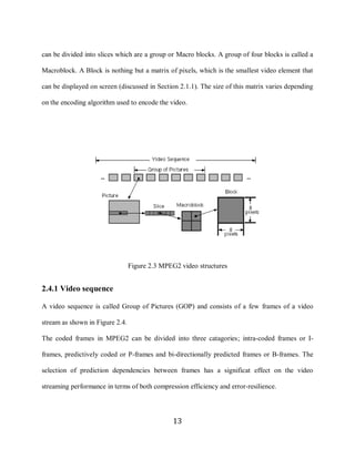
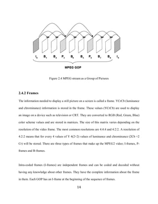
![11
MPEG2 is the most popular format for DVD authoring and digital video broadcasting as
it supports video of very high resolution. The most significant enhancement in MPEG2 relative
to MPEG1 was the addition of support for interlaced video. Interlaced scanning is the method in
which odd and even lines in a frame are refreshed alternately. Progressive or non-interlaced
scanning is the opposite of interlaced method for displaying, in which the lines of each frame are
drawn in sequence.
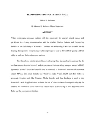
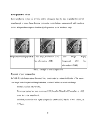
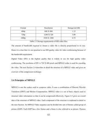
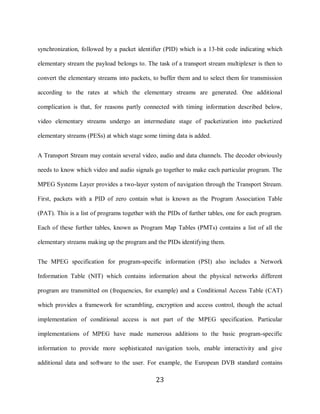
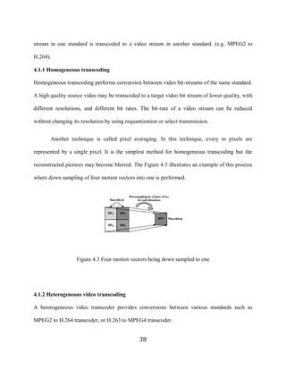
High Definition video [13] is a compression standard in which a significantly high
resolution is used for encoding video. Typical resolution of a high definition video is 720p or
1080p. Here the number 720 or 1080 specify number of horizontal lines in each frame of the
video. The Figure 2.6 shows a comparison between different resolutions.
Figure 2.2 Comparison of the resolution in various standards
High Definition (HD) provides the highest quality of video among all the broadcasting standards
available today. But the amount of bandwidth required to transmit HD video makes it difficult to
stream over IP. Table 2.6 gives the amount of storage required to store video HD quality. The
duration of all the video files is one hour [14].
11](https://image.slidesharecdn.com/transcoding-transport-stream-mpeg21267/85/Transcoding-Transport-Stream-MPEG2-21-320.jpg)
![26
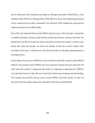
The Figures 3.1 and 3.2 illustrate the VBrick 6200 in front and rear view. The various
input/output ports of a VBrick 6200 are shown in Figure 3.1. When a VBrick is connected to the
network and is streaming the video, the display in the front of the VBrick can be used to monitor
the IP address assigned to the VBrick and other control information as shown in Figure 3.2.
Figure 3.1 VBrick 6200 rear view Figure 3.2 VBrick 6200 front view
The VBrick encoder can receive video input from a live camera via an S-Video input,
from a DVD player or an MPEG2 video file stored in a built-in hard-drive of the VBrick. The
video stream generated by a VBrick can be received and viewed using VBrick decoder or a
software decoder. VBrick provides a software called the Stream Player Plus [15] which can be
used to decode video streams (generated by a VBrick encoder) being received over IP network.
The Figure 3.3 illustrates VBrick being used as an encoder/decoder.
26](https://image.slidesharecdn.com/transcoding-transport-stream-mpeg21267/85/Transcoding-Transport-Stream-MPEG2-36-320.jpg)
![30
While the basics of multicasting are easily understood, a new set of routing protocols are
needed for a multicast network to scale to global size. In IPv4, the range of addresses from
224.0.0.1 to 239.255.255.255 is classified as Class D IP addresses.
Internet Group-Membership Protocol [16] (IGMP) is the multicast protocol. IGMP relies
on Class D IP addresses for the creation of multicast groups. IGMP is used to dynamically
register individual hosts in a multicast group with a Class D address. Hosts identify group
memberships by sending IGMP messages, and traffic is sent to all members of that multicast
group. Under IGMP, routers listen to IGMP messages and periodically send out queries to
discover which groups are active or inactive on particular LANs. Routers communicate with
each other by using one or more protocols to build multicast routes for each group.
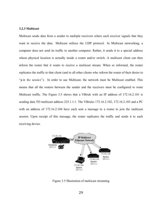
Protocol Independent Multicast [17] (PIM) sparse mode is optimized for internetworks
with many data streams but a relatively few number of LANs. It defines a rendezvous point that
is then used as a registration point to facilitate the proper routing of packets. When multicast
traffic is sent, the router nearest the source sends data to the rendezvous point. When a receiver
wants to receive data, the last-hop router (with respect to the receiver) registers with the
rendezvous point. A data stream flows from the sender to the rendezvous point and to the
receiver. Routers in the path from source to destination optimize the path and automatically
remove any unnecessary hops, even at the rendezvous point.
Multicast Open Shortest Path First (MOSPF) is an extension of OSPF. MOSPF employs
a unicast routing protocol so that every router is aware of all available links, and each calculates
routes from the source to all possible group members. MOSPF calculates the routes for each
30](https://image.slidesharecdn.com/transcoding-transport-stream-mpeg21267/85/Transcoding-Transport-Stream-MPEG2-40-320.jpg)
![31
source/multicast group pair when the router receives traffic for that pair, and routes are cached
until a topology change occurs. MOSPF then recalculates the topology. MOSPF works only in
networks that use OSPF, and where there are a small number of multicast groups. MOSPF takes
up a lot of router CPU bandwidth when there are many multicast groups, or where those groups
change often.
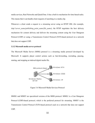
3.3 Media control protocols
There are three different protocols used for media control in video streaming applications. They
are:
1. Real Time Streaming Protocol (RTSP)
2. Microsoft Media Server protocol (MMS)
3. Hypertext Transfer Protocol (HTTP)
The variables such as error checking method, data compression method and end-of-file
acknowledgements are determined by the type of protocol. The control-protocol plug-in on the
server receives the request from clients, determines the action indicated by the request (for
example, start or stop streaming) and passes the command to the streaming server. MMS and
RTSP can be used in combination with both UDP and TCP protocols.
3.3.1 Real time streaming protocol
RTSP [18] can be used to deliver video content as a unicast or a multicast stream. RTSP is an
application-level protocol created to control the delivery of real-time data, such as audio and
video content. RTSP is used by most of the media delivery services like M icro so ft‟s W indo w s
31](https://image.slidesharecdn.com/transcoding-transport-stream-mpeg21267/85/Transcoding-Transport-Stream-MPEG2-41-320.jpg)
![33
3.3.3 Hypertext transfer protocol
HTTP [19] can be used to stream content from a streaming server to a client program. Mostly,
this protocol is used for media control during video streaming if the content is being streamed
through a firewall. HTTP uses port 80 which is not blocked by the firewalls.
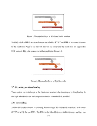
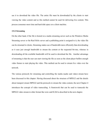
3.4 Protocol rollover
The ability of the server to choose the right protocol for a client depending on its environment is
called protocol rollover. It is useful when the server is receiving requests from a variety of
clients. The clients may be connected through a firewall. The server establishes the optimal
connection to the client when protocol rollover is used. The client sends information about its
type (version) and what protocols it can support when requesting a video stream from the server.
The server uses the best protocol for the situation by using the information sent by the client and
the comparing it with the protocols enabled on the server.
In typical scenarios the first attempt to connect to the server succeeds and no further
attempts are made to connect to the server. If an attempt is unsuccessful protocol rollover is
performed and the next optimal protocol is used for streaming. During the process of protocol
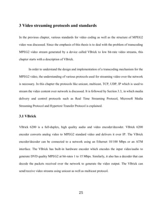
rollover the client may experience brief but unnoticeable latency. The Figure 3.7 illustrates
protocol rollover in Windows Media services. The most preferred protocol to transmit windows
media is MMSU (using UDP). If the network between the server and the client does not support
UDP protocol then MMST (TCP) is used. If there is a firewall between the server and the client
the server chooses HTTP protocol to stream the media contents to the client.
33](https://image.slidesharecdn.com/transcoding-transport-stream-mpeg21267/85/Transcoding-Transport-Stream-MPEG2-43-320.jpg)
![39
A heterogeneous transcoder needs a syntax conversion module, and may change the
picture type, picture resolution, directionality of MVs, and picture rate. A heterogeneous
transcoder must adjust the features of the incoming video to enable the features of the outgoing
video [20]. A number of differences exist among various video coding standards which makes
heterogeneous transcoding more complex. Table 4.1 below shows some of the major differences
between popular coding standards.
Table 4.1 Key features of video compression standards
39](https://image.slidesharecdn.com/transcoding-transport-stream-mpeg21267/85/Transcoding-Transport-Stream-MPEG2-49-320.jpg)
![40
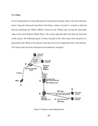
Live broadcast of transcoded stream is more complex than transcoding video for on-
demand broadcast. It involves more resources and has a time constraint for generating the
transcoded stream. Designing a whole new transcoder for the purpose of transcoding VBrick
stream into wmv or real video format is a tedious process. Hence existing software like Windows
Media Encoder [21] and Real Producer [22] is used in the framework (discussed in the next
Section) to convert VBrick video stream into low bit rate formats.
4.2 Transcoding VBrick transport stream MPEG2
In this Section, the various ways in which the transport stream MPEG2 generated by a (VBrick)
device at higher bit rates can be transmitted to large number of people is discussed.
The multicast transport stream MPEG2 generated by the VBrick can be transmitted to the
audience without Internet2 connectivity in two ways.
1. On demand streaming of transcoded video
2. Live broadcast of transcoded video at lower bit rates
The recorded video from a VBrick session needs to be transcoded to lower bitrates and
appropriate format (.wmv or .rm) to enable it for on-demand streaming. The video authoring
programs such as Windows Media Encoder, Real Producer or Ulead Express expect the input to
be in program stream MPEG2 format and do not have the capability of processing transport
stream MPEG2. Hence initial attempts to compress the transport stream MPEG2 to .wmv or .rm
format using Windows media encoder or Real Producer resulted in output stream with no audio.
To solve this problem two-pass encoding of the recorded files is done. In the first pass the
40](https://image.slidesharecdn.com/transcoding-transport-stream-mpeg21267/85/Transcoding-Transport-Stream-MPEG2-50-320.jpg)
![41
transport stream MPEG2 is converted to MPEG1 or program stream MPEG2. This stream is then
converted to .wmv or .rm format using Windows Media Encoder or Real Producer respectively.
Once the compressed video is produced, it is placed on the Windows Media Server or Helix
streaming server and can be accessed on-demand by clients using appropriate request to web
server URL.
The solution discussed above cannot be used for live broadcast of transcoded stream
because of the time constraint. Windows Media Encoder and Real Producer transcode a video
stream and generate an output stream at desired bit-rate and format. But the input to these
encoders must be uncompressed video from a video/audio capture card or video compressed
using a codec that the above software can decode. The software listed above only decode
Program stream MPEG2. When Transport stream MPEG2 is used as an input to generate the
transcoded stream, the output stream does not contain the audio data (discussed in Section 2.5).
To solve this problem Microsoft DirectShow [23] is used. On Microsoft Windows platform
Microsoft DirectShow provides architecture for processing media (video and sound).
DirectShow provides high-quality capture and playback of multimedia streams. It supports
capture from digital and analog devices based on the Windows Driver Model or Video for
Windows (VfW).
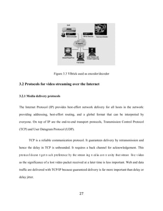
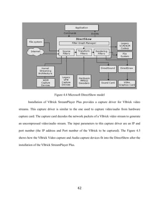
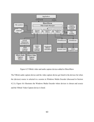
The following Figure 4.4 shows the relationship between an application, the DirectShow
components, and some of the hardware and software components. As illustrated, DirectShow
filters communicate with, and control, a wide variety of devices, including the local file system,
TV tuner and video capture cards, VfW codecs, the video display, and the sound card.
41](https://image.slidesharecdn.com/transcoding-transport-stream-mpeg21267/85/Transcoding-Transport-Stream-MPEG2-51-320.jpg)
![45
4.2.1 Windows media server
Windows Media Streaming server [24] is a server program that can be installed (configured) on a
Windows 2000/2003 server. The URL
http://www.microsoft.com/windows/windowsmedia/forpros/serve/wmservices.aspx can be
referred to get instructions in configuring Windows Media Services on Windows 2003 server.
Ideally two computers are used in this framework. The first one (referred to as Window Media
Encoder) is used to transcode the transport stream MPEG2 from the VBrick to a lower bit-rate
.wmv format. The second one is used to host the Windows Media Server. There are two ways of
serving this transcoded .wmv stream to the clients.
1. The .wmv stream can be PULLed directly from the Windows Media Encoder (WME) by
connecting to the URL specified by http://ipaddress:port, where ipaddress is the IP
address of WME and port is the configured port on WME for serving the transcoded
stream. There is limitation on number of users that can connect to the windows media
encoder program as the computational load on it increases with increased number of
clients connecting to it. This method is useful when the transcoded stream is to be served
to less number of clients.
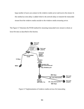
2. In the second method, the transcoded .wmv stream is PUSHed to a broadcast point on a
Windows media streaming server. Clients can then connect to the broadcast point using
the URL mms://server1/broadcastpoint and receive the transcoded stream live. The
Windows Media Streaming server provides more capabilities such as security and
administration for serving the .wmv stream. When compared to the earlier method, a
45](https://image.slidesharecdn.com/transcoding-transport-stream-mpeg21267/85/Transcoding-Transport-Stream-MPEG2-55-320.jpg)
![47
VBrick stream can be transcoded to a wmv stream by starting a new broadcast session in
W indo w s M ed ia E nco der and selecting the so urce as “devices” (as sho w n in F igure 4.8). T he
VBrick Video Capture and the VBrick Audio Capture is selected as the video and audio device
respectively.
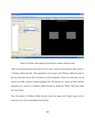
Figure 4.8 Windows Media Encoder session with VBrick devices selected as input
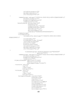
Then a number of settings like the video resolution, frame rate and bit-rate are set to start an
encoding session that transcodes the input VBrick stream into wmv [27]. An XML file
containing parameters for Windows Media Encoder to transcode a VBrick stream into a wmv
format is as follows:
<?xml version="1.0"?>
<WMEncoder major_version="9"
minor_version="0"
47](https://image.slidesharecdn.com/transcoding-transport-stream-mpeg21267/85/Transcoding-Transport-Stream-MPEG2-57-320.jpg)
![50
</videoinfoheader>
</wmmediatype>
</streamconfig>
</profile>
]]>
</WMEncoder_Profile>
<UserData >
<WMENC_LONG Name="EncodingDest" Value="2" />
<WMENC_STRING Name="EncodingAudio0" />
<WMENC_STRING Name="EncodingVideo0" />
<WMENC_STRING Name="EncodingScript0" />
<WMENC_LONG Name="EncodingBitrate0Video0CustomW" Value="360" />
<WMENC_LONG Name="EncodingBitrate0Video0CustomH" Value="240" />
</UserData>
</WMEncoder>
Using the above configuration, the transcoded wmv stream of resolution 360 x 240 and the frame
rate is 30 frames per second can be generated. The stream is served to the clients using the PULL
method and URL to access the output stream will be http://serverIP:8080.
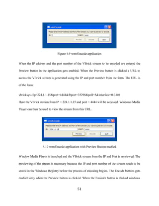
A Graphical User Interface is designed in Qt [29] to simplify the use of this framework. The
application looks as shown in Figure 4.9. The source code for the application is given in
Appendix B. One of the interesting things to note is that the XML configuration file (shown
abo ve) o f a W indo w s M ed ia E nco der sho w n abo ve do esn‟t co n tain the IP Address and Port
number of the VBrick stream to be transcoded.
Whenever VBrick StreamPlayer Plus is used to access a VBrick stream, the IP address and the
Port number of the stream gets stored in the Windows registry. When the capture driver is used
to capture stream using encoding software, it accesses the same stream that is directed by the
stored values in the registry. This protocol has been incorporated in the GUI application. This
application is name wmvEncode.
50](https://image.slidesharecdn.com/transcoding-transport-stream-mpeg21267/85/Transcoding-Transport-Stream-MPEG2-60-320.jpg)
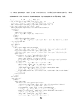
![52
media encoder is launched and the VBrick stream that was previewed is given as input to the
encoder. The Encoder reads the input parameters from an XML file which has all the parameters
required to start the encoding process. Once the session starts and enough frames are buffered to
generate the w m v stream the “S tart E nco ding ” butto n can be pressed to start the enco d ing
process.
4.2.2 Real helix server
Similar to the approach discussed in Section 4.2.1 Real Producer [22] and Real Helix server can
be used to broadcast the transcoded transport stream MPEG2 a low bit-rates. Real Producer is
software that can encode uncompressed video input into real video format. The Figure 4.11
shows a Real Producer session in which the VBrick devices are selected as inputs.
Figure 4.11 Real Producer 11 session with VBrick devices selected as input
52](https://image.slidesharecdn.com/transcoding-transport-stream-mpeg21267/85/Transcoding-Transport-Stream-MPEG2-62-320.jpg)
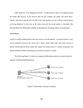
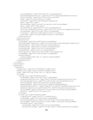
![53
The Figure 4.12 shows the use of Real Producer and Helix server [25] to broadcast the
transcoded rm format. The MPEG2 transport stream is transcoded to the desirable bit rate and is
streamed to a mount point (TV2) on a preconfigured Real Helix server. The web URL
“http://service.real.com/help/library/guides/helixuniversalserver/realsrvr.htm” can be referred to
configure a Real Helix Server. The end-user clients can then connect to the server to view the
stream using the RTSP URL (as shown in the Figure 4.12) from a Real Player.
Figure 4.12 Implementation of the real networks for transcoding
53](https://image.slidesharecdn.com/transcoding-transport-stream-mpeg21267/85/Transcoding-Transport-Stream-MPEG2-63-320.jpg)
![56
</streamContext>
</stream>
<stream xsi:type="audioStream">
<codecFlavor type="uint">23</codecFlavor>
<codecName type="string">cook</codecName>
<encodingComplexity type="string">high</encodingComplexity>
<pluginName type="string">rn-audiocodec-realaudio</pluginName>
<streamContext type="bag">
<audioMode type="string">music</audioMode>
<presentationType type="string">audio-video</presentationType>
</streamContext>
</stream>
<stream xsi:type="audioStream">
<codecFlavor type="uint">14</codecFlavor>
<codecName type="string">cook</codecName>
<encodingComplexity type="string">high</encodingComplexity>
<pluginName type="string">rn-audiocodec-realaudio</pluginName>
<streamContext type="bag">
<audioMode type="string">voice</audioMode>
<presentationType type="string">audio-only</presentationType>
</streamContext>
</stream>
<stream xsi:type="audioStream">
<codecFlavor type="uint">4</codecFlavor>
<codecName type="string">raac</codecName>
<encodingComplexity type="string">high</encodingComplexity>
<pluginName type="string">rn-audiocodec-realaudio</pluginName>
<streamContext type="bag">
<audioMode type="string">music</audioMode>
<presentationType type="string">audio-only</presentationType>
</streamContext>
</stream>
</streams>
</audience>
</audiences>
</job>
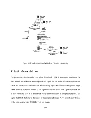
4.2.3 VideoLan client
H.264 is a substantially different codec from the previous MPEG and ITU standards (see Table
4.1). It is a joint effort of MPEG and ITU and aims to deliver high-quality video at all bit rates.
VideoLan Client [26] is a tool that provides capability to transcode MPEG2 stream to H.264 in
real time. The following Figure 4.13 illustrates the use of VideoLan Client to transcode transport
stream MPEG2 in real time and broadcast it in low bit-rates. A more detailed description of this
process is given in Appendix B
56](https://image.slidesharecdn.com/transcoding-transport-stream-mpeg21267/85/Transcoding-Transport-Stream-MPEG2-66-320.jpg)
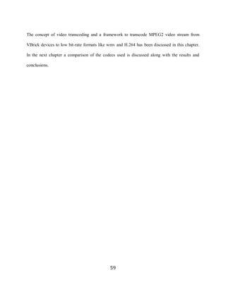
![58
MSE for two m×n images I and K where one of the images is considered a noisy approximation
of the other is computed by the following equation:
… … … … … … … … … … … … … … … [1]
In equation 1, m and n are the number of rows and columns respectively in the input images I
and K. I (i, j) represents the pixel of image I from ith row and jth column.
PSNR can be computed using the following equation:
… … … … … … … … … … … … … … … … … … [2]
In equation 2, R is the maximum fluctuation in the input image data type. For example, if the
input image has a double-precision floating-point data type, then R is 1. If it has an 8-bit
unsigned integer data type, R is 255, etc. Average PSNR of a compressed video file is the
average of all the PSNR of all the video frames in the video. The typical value of average PSNR
of a compressed video is between 30 and 45. PSNR is a measurement that gives an estimate of
the quality of the compressed video with respect to the original video file.
58](https://image.slidesharecdn.com/transcoding-transport-stream-mpeg21267/85/Transcoding-Transport-Stream-MPEG2-68-320.jpg)
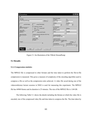
![60
5 Results and conclusions
In the previous chapter, the implementation of framework to transcode VBrick MPEG2 transport
stream to wmv, real video and H.264 has been discussed. This chapter contains a comparison of
the three types of mechanisms described earlier. Factors like the compression ratio, quality of the
transcoded stream and the time taken by the encoder to transcode the stream is measured and the
results are discussed.
VBrick StreamPump [30] as shown in Figure 5.1 is a tool provided by VBrick Systems.,
is used to stream a MPEG2 transport stream video file to a unicast or a multicast address. A
multicast MPEG2 transport stream generated by the VBrick StreamPump is identical to the one
generated by the VBrick 6200 and so it has been used to simulate a VBrick stream. To simulate
the broadcast of VBrick transport stream MPEG2, a video file saved during one of the
videoconference lecture sessions in NSEI is used. The MPEG2 file has 44960 frames and is of
duration 25 minutes. The size of the MPEG2 file is 1.04 GB.
The configuration of the machine used to transcode the VBrick transport stream MPEG2
is as follows:
Processor – AMD Turion dual core 1.6 GHz (512 KB L2 cache)
Random Access Memory – 1 GB
Hard Disk – 80 GB 5400 rpm SATA
Network card – 1 Gbps Ethernet
Operating system – Windows XP professional (service pack 2)
60](https://image.slidesharecdn.com/transcoding-transport-stream-mpeg21267/85/Transcoding-Transport-Stream-MPEG2-70-320.jpg)
![62
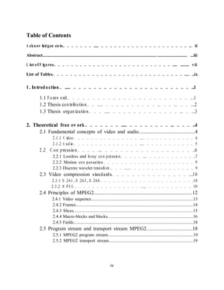
an encoder to compress the input file to the desired format gives a measure of the complexity of
encoding algorithm.
Time taken to
Format Bitrate Size of compressed compress (seconds) % Compression
MPEG2 6000Kbps 1.04 GB N/A N/A
MPEG1 3200Kbps 599 MB 608 45.5
.wmv 342Kbps 62.6 MB 1525 94.3
.rm 350Kbps 65.2 MB 3828 94.16
H.264 350Kbps 66.2 MB 864 93.97
Table 5.1 Compression statistics
All three formats (wmv, rm and H.264) attain similar compression ratios at nearly 94%. The time
taken to compress the file is highest for the Real format.
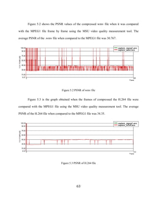
5.1.2 Quality of transcoded video
To measure the quality of the codec (wmv and H.264) the VBrick transport stream MPEG2 from
the VBrick StreamPump is used as input and the transcoded stream is saved to a file for its
comparison with the MPEG2 file. The MSU video quality measurement tool [28] is a tool that
can measure the PSNR of two input video files frame by frame. The original MPEG2 file and the
transcoded file were compared using the MSU tool and the average PSNR of the transcoded files
is measured.
62](https://image.slidesharecdn.com/transcoding-transport-stream-mpeg21267/85/Transcoding-Transport-Stream-MPEG2-72-320.jpg)
![69
Internet2 (to receive the multicast stream) connect to the low bit-rate live video stream generated
by the Windows Media encoder.
5.3 Future work
Among other things the following can be done to improve the overall usability and the security
of the content when using the approach described in this thesis.
There may be several occasions when the content that is being streamed needs to be
secure and should not be accessed by unauthorized users. If the users connect to the streaming
server only from a particular domain (e.g. users connecting from within a University campus),
then the users receiving the low bit-rate streams can be restricted by IP addresses. But most of
the times the video stream is broadcasted to users that are in different locations. The webpage
that front ends the URL to access live video stream and the web pages that host archived videos
can be protected by using authentication like .htaccess [31]. The use of authentication can limit
the number of users that receive live video stream and the users that access archived video files.
From the observation in the Section 5.1.3 it is clear that the total delay can be reduced by
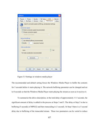
changing the buffering at the Encoder and the end user client. The optimal value for these
buffering parameters can be determined by further experimentation.
This thesis has designed and implemented a framework to transcode high quality
transport stream MPEG2 generated by VBrick to low bit-rate formats in real-time. The
transcoded video can be streamed to the users on the Internet who intend to watch the video
69](https://image.slidesharecdn.com/transcoding-transport-stream-mpeg21267/85/Transcoding-Transport-Stream-MPEG2-79-320.jpg)

![75
/************************************************************
* Filename: main.cpp
* Author: Shashi Shilarnav
*
* This program contains the main() function that gets executed
* whenever this application is run. An object of type wmvEncode
* is created and displayed.
*
*
*************************************************************/
#include <QApplication>
#include "wmvEncode.h"
int main(int argc, char *argv[])
{
QApplication app(argc, argv);
wmvEncode wmvEncodeWindow;
wmvEncodeWindow.show();
return wmvEncodeWindow.exec();
}
__________________________________________________________________
/******************************************************************
* Filename: wmvEncode.h
* Author: Shashi Shilarnav
*
* wmvEncode.h is a header file and contains the definition of the class wmvEncode.
*
*******************************************************************/
#ifndef WMVENCODE_H
#define WMVENCODE_H
#include <QDialog>
class QDialogButtonBox;
class QLabel;
class QLineEdit;
class QPushButton;
class wmvEncode : public QDialog
{
Q_OBJECT
public:
wmvEncode(QWidget *parent = 0);
private slots:
void previewStream();
void enablePreviewButton();
void enableEncodeButton();
void launchEncoder();
75](https://image.slidesharecdn.com/transcoding-transport-stream-mpeg21267/85/Transcoding-Transport-Stream-MPEG2-85-320.jpg)