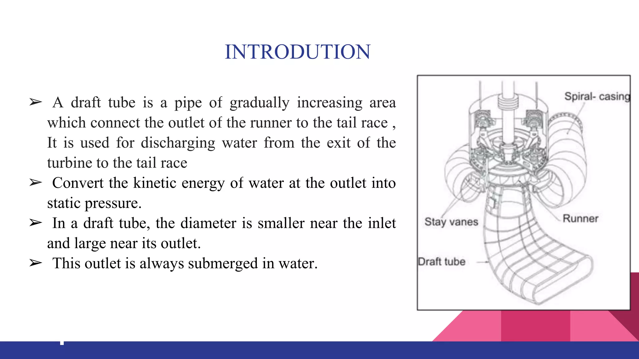
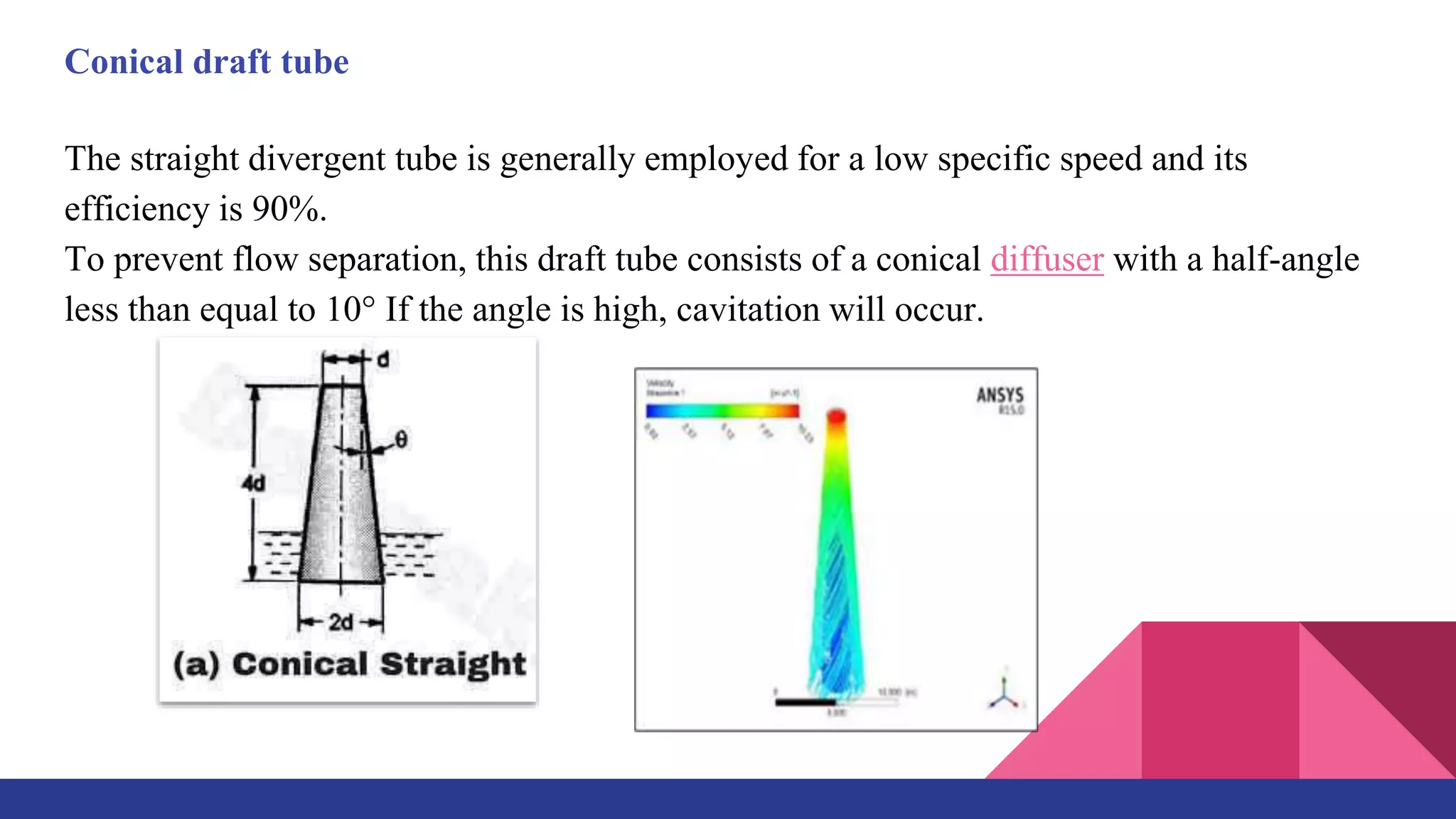
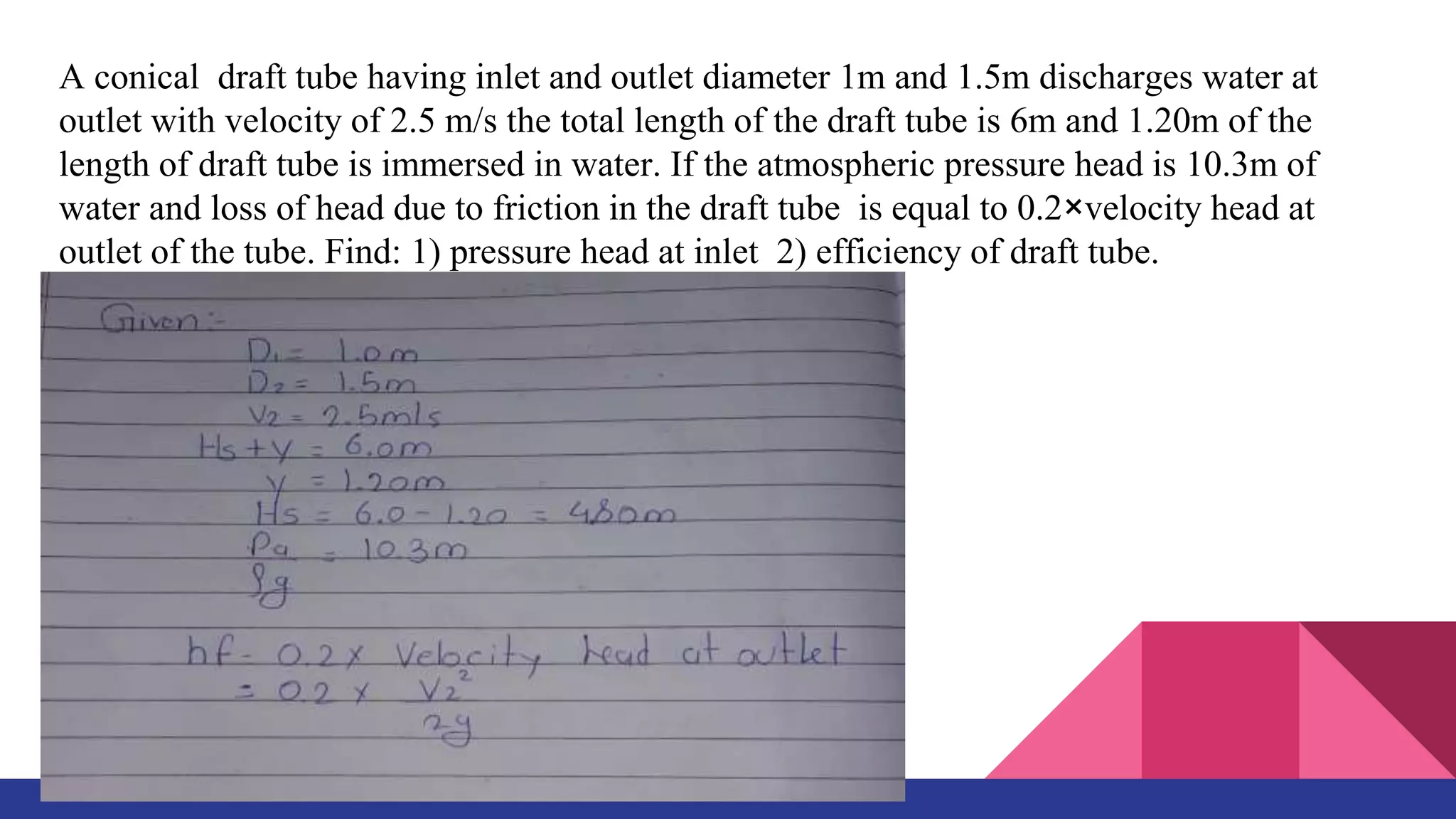
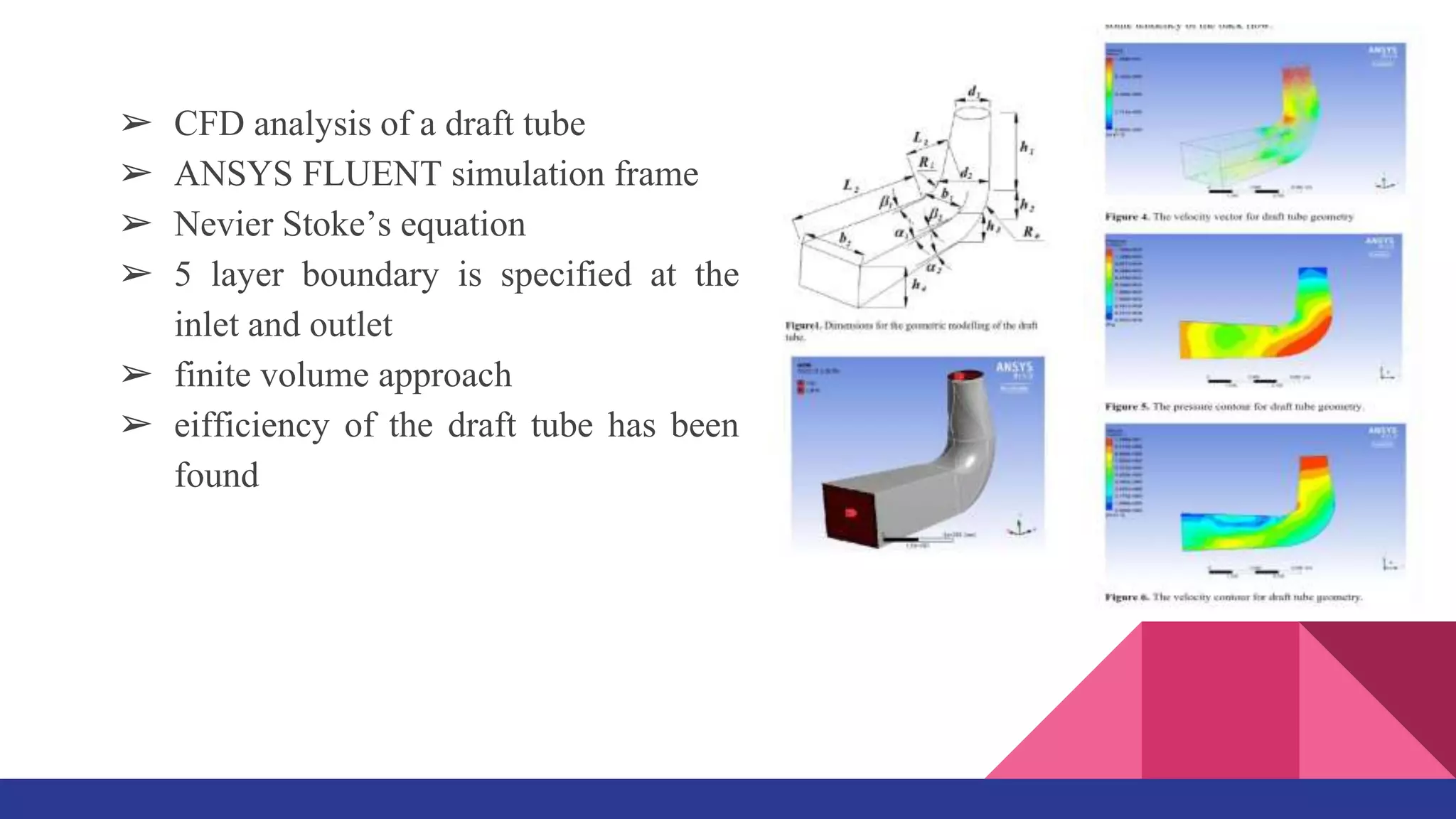
BRACT’s Vishwakarma Institute of Information Technology
Department of Mechanical Engineering
Second Year B.Tech Mechanical - 2022-23 (Semester -IV)
Name of the course - Fluid Mechanics and Machinery
Skill and Competency Examination (SCE)
Presentation on
Topic : STUDY ON DRAFT TUBE
Batch : C3
Sr.No GRN Roll Number Name
1 22220186 253063 Saurabh Dadasaheb Ghode
2 22220242 253069 Sandesh Bharat Mali
3 22220292 253074 Abhirav Arun Sathe
4 22220306 253076 Venkatesh Krishnakant Kulkarni
INTRODUTION
➢ A draft tube is a pipe of gradually increasing area
which connect the outlet of the runner to the tail race ,
It is used for discharging water from the exit of the
turbine to the tail race
➢ Convert the kinetic energy of water at the outlet into
static pressure.
➢ In a draft tube, the diameter is smaller near the inlet
and large near its outlet.
➢ This outlet is always submerged in water.
PURPOSE OF DRAFT TUBE
➢ To reduce velocity of water at outlet of runner as well as to increase pressure of water
at outlet.
➢ Possible to install the turbine above the tailrace level without loss head.
➢ Net head on turbine increase and increase in efficiency.
➢ To avoid backflow in turbine.
➢ To reduce cavitation.
➢ Impulse turbines does not require draft tube only reaction turbine need it.
Types of Draft Tube
1. Conical Draft Tube
2. Moody Spreading Draft Tube
3. Simple Elbow Draft Tube
4. Elbow Draft Tube with a varying cross section
Conical draft tube
The straight divergent tube is generally employed for a low specific speed and its
efficiency is 90%.
To prevent flow separation, this draft tube consists of a conical diffuser with a half-angle
less than equal to 10° If the angle is high, cavitation will occur.
Moody Spreading Tube:
The outlet of the draft tube is split into two sections
in this form of the draft tube. Moody draft tube is
similar to a conical draft tube and is with a central
core component that divides the outlet into two parts.
The efficiency of this type of tube design is almost
88%.
Simple elbow draft tube
The shape of the tube is like an elbow in a simple Elbow draft
Tube.
In this type of draft tube, the cross-section area remains the same
for the entire length of the draft tube. The inlet and outlet of the
draft tube are circular.
This draft tube is used at low head positions and the turbine is to
be mounted next to the tailrace.
This tube has a moderate efficiency of around 60%.
Elbow draft tube with varying cross-section
➢ An elbow draft tube with varying cross-section is an
improvement of a simple elbow draft.
➢ The inlet is circular and the outlet is rectangular in this type.
➢ The performance of this type of draft tube is used with the
Kaplan Turbine at about 70%.
➢ It required less space.
Applying bernoulli’s equation inlet and outlet section
(P1/ρg) + (V12/2g) + Z1= (P2/ρg ) + (V22/2g) + Z1 + hf
EFFICIENCY OF DRAFT TUBE
NUMERICAL ON DRAFT TUBE
Q. A water turbine has a velocity of 6 m/per at the entrance to the draft tube and the
velocity of 1.2 m/sec at the exit. For friction loss of 0.1M and the tail water 5 meter below
the entrance of the draft tube find the pressure head at entrance.
Given:
V1=6m/sec
V2=1.2m/sec
hf=0.1m
Applying B.E equation on both section
(P1/ρg) + Z1+ (V12/2g) = (Pa/ρg ) + Z1 + (V22/2g) + hf
(P1/ρg) + (5+y) = (62/2*9.81) = (Pa/ρg ) + y +0 + (1.22/2g) +0.1
(P1/ρg) + 5 + 1.813 = (Pa/ρg ) + 0.0734 + 0.1
(P1/ρg) = 10.33 + 0.07341 + 0.1-5 - 1.813 ( absolute pressure is 0)
(P1/ρg)=3.66mm of h2o
(P1/ρg)= -6.66 mm of h2o ( considering atmospheric pressure zero)
10_Atmosphere__________________________________________________________
9
8
7
6
5
4
3
2
1
0_Absolute_____________________________________________________________
A conical draft tube having diameter at the top as 2.0m and pressure head at 7m of water
(vacuum), discharge water at the outlet with a velocity of 1.2 m/s at the rate of 25 m3/s.
If atmospheric pressure head is 10.3m of water and loses between the inlet and outlet of
the draft tubes and negligible. find out the length of draft to immersed in water. total
length of the tube is 5m.
A conical draft tube having inlet and outlet diameter 1m and 1.5m discharges water at
outlet with velocity of 2.5 m/s the total length of the draft tube is 6m and 1.20m of the
length of draft tube is immersed in water. If the atmospheric pressure head is 10.3m of
water and loss of head due to friction in the draft tube is equal to 0.2×velocity head at
outlet of the tube. Find: 1) pressure head at inlet 2) efficiency of draft tube.
ADVANTAGES OF A DRAFT TUBE
1. It is an important component which is used to transform the water into energy.
2. It is generally found in the piping system.
3. It is also found in Dams where the turbine finds it difficult to deliver the mechanical
work.
4. Draft tubes Prevent the splashing water coming out of the runner and its guide water
to the tailrace.
DISADVANTAGES OF DRAFT TUBE
➢ Increased capital cost: The installation of a draft tube requires additional construction
and material costs, which can increase the overall capital cost of the system.
➢ Space requirements: Draft tubes require a significant amount of space, which can be a
challenge in applications where space is limited.
➢ Maintenance requirements: Draft tubes can be difficult to maintain, particularly in
environments where corrosion or fouling can occur. Regular cleaning and inspection
may be required to ensure optimal performance.
➢ Reduced efficiency at low loads: Draft tubes are designed to work most efficiently at
full load, and their efficiency can decrease significantly at low loads. This can be a
problem in applications where the load on the system varies widely.
APPLICATION
➢ This draft tube is mostly used in Hydroelectric power plants.
➢ .You can see the usage of the draft tube in the Kaplan turbine and Francis turbine as a
common part
FUTURE SCOPE
J-Groove
➢ Suppression of vortex and cavitation surge
➢ a series of CFD analysis conducted range
of partial load, design condition and
overload
➢ suppress the abnormal phenomena to some
extents
➢ groove length, depth and width normalized
by the diameter of outlet of turbine runner
➢ CFD analysis of a draft tube
➢ ANSYS FLUENT simulation frame
➢ Nevier Stoke’s equation
➢ 5 layer boundary is specified at the
inlet and outlet
➢ finite volume approach
➢ eifficiency of the draft tube has been
found
➢ A multi-disciplinary collaborative design
optimization platform
➢ collaborate and streamline the design
process, leading to more efficient and
effective designs.
1. Fluid dynamics analysis
2. Structural analysis
3. Optimization algorithms
4. Collaboration tools
➢ Overall, This would be powerful tool for
optimizing the design of critical
components
➢ This leads to more efficient and effective
hydraulic turbines.
Thank You…

Draft Tube PPT.pptx

  • 1.
    BRACT’s Vishwakarma Instituteof Information Technology Department of Mechanical Engineering Second Year B.Tech Mechanical - 2022-23 (Semester -IV) Name of the course - Fluid Mechanics and Machinery Skill and Competency Examination (SCE) Presentation on Topic : STUDY ON DRAFT TUBE Batch : C3 Sr.No GRN Roll Number Name 1 22220186 253063 Saurabh Dadasaheb Ghode 2 22220242 253069 Sandesh Bharat Mali 3 22220292 253074 Abhirav Arun Sathe 4 22220306 253076 Venkatesh Krishnakant Kulkarni
  • 2.
    INTRODUTION ➢ A drafttube is a pipe of gradually increasing area which connect the outlet of the runner to the tail race , It is used for discharging water from the exit of the turbine to the tail race ➢ Convert the kinetic energy of water at the outlet into static pressure. ➢ In a draft tube, the diameter is smaller near the inlet and large near its outlet. ➢ This outlet is always submerged in water.
  • 3.
    PURPOSE OF DRAFTTUBE ➢ To reduce velocity of water at outlet of runner as well as to increase pressure of water at outlet. ➢ Possible to install the turbine above the tailrace level without loss head. ➢ Net head on turbine increase and increase in efficiency. ➢ To avoid backflow in turbine. ➢ To reduce cavitation. ➢ Impulse turbines does not require draft tube only reaction turbine need it.
  • 4.
    Types of DraftTube 1. Conical Draft Tube 2. Moody Spreading Draft Tube 3. Simple Elbow Draft Tube 4. Elbow Draft Tube with a varying cross section
  • 5.
    Conical draft tube Thestraight divergent tube is generally employed for a low specific speed and its efficiency is 90%. To prevent flow separation, this draft tube consists of a conical diffuser with a half-angle less than equal to 10° If the angle is high, cavitation will occur.
  • 6.
    Moody Spreading Tube: Theoutlet of the draft tube is split into two sections in this form of the draft tube. Moody draft tube is similar to a conical draft tube and is with a central core component that divides the outlet into two parts. The efficiency of this type of tube design is almost 88%.
  • 7.
    Simple elbow drafttube The shape of the tube is like an elbow in a simple Elbow draft Tube. In this type of draft tube, the cross-section area remains the same for the entire length of the draft tube. The inlet and outlet of the draft tube are circular. This draft tube is used at low head positions and the turbine is to be mounted next to the tailrace. This tube has a moderate efficiency of around 60%.
  • 8.
    Elbow draft tubewith varying cross-section ➢ An elbow draft tube with varying cross-section is an improvement of a simple elbow draft. ➢ The inlet is circular and the outlet is rectangular in this type. ➢ The performance of this type of draft tube is used with the Kaplan Turbine at about 70%. ➢ It required less space.
  • 9.
    Applying bernoulli’s equationinlet and outlet section (P1/ρg) + (V12/2g) + Z1= (P2/ρg ) + (V22/2g) + Z1 + hf
  • 10.
  • 11.
    NUMERICAL ON DRAFTTUBE Q. A water turbine has a velocity of 6 m/per at the entrance to the draft tube and the velocity of 1.2 m/sec at the exit. For friction loss of 0.1M and the tail water 5 meter below the entrance of the draft tube find the pressure head at entrance. Given: V1=6m/sec V2=1.2m/sec hf=0.1m
  • 12.
    Applying B.E equationon both section (P1/ρg) + Z1+ (V12/2g) = (Pa/ρg ) + Z1 + (V22/2g) + hf (P1/ρg) + (5+y) = (62/2*9.81) = (Pa/ρg ) + y +0 + (1.22/2g) +0.1 (P1/ρg) + 5 + 1.813 = (Pa/ρg ) + 0.0734 + 0.1 (P1/ρg) = 10.33 + 0.07341 + 0.1-5 - 1.813 ( absolute pressure is 0) (P1/ρg)=3.66mm of h2o (P1/ρg)= -6.66 mm of h2o ( considering atmospheric pressure zero)
  • 13.
  • 14.
    A conical drafttube having diameter at the top as 2.0m and pressure head at 7m of water (vacuum), discharge water at the outlet with a velocity of 1.2 m/s at the rate of 25 m3/s. If atmospheric pressure head is 10.3m of water and loses between the inlet and outlet of the draft tubes and negligible. find out the length of draft to immersed in water. total length of the tube is 5m.
  • 16.
    A conical drafttube having inlet and outlet diameter 1m and 1.5m discharges water at outlet with velocity of 2.5 m/s the total length of the draft tube is 6m and 1.20m of the length of draft tube is immersed in water. If the atmospheric pressure head is 10.3m of water and loss of head due to friction in the draft tube is equal to 0.2×velocity head at outlet of the tube. Find: 1) pressure head at inlet 2) efficiency of draft tube.
  • 19.
    ADVANTAGES OF ADRAFT TUBE 1. It is an important component which is used to transform the water into energy. 2. It is generally found in the piping system. 3. It is also found in Dams where the turbine finds it difficult to deliver the mechanical work. 4. Draft tubes Prevent the splashing water coming out of the runner and its guide water to the tailrace.
  • 20.
    DISADVANTAGES OF DRAFTTUBE ➢ Increased capital cost: The installation of a draft tube requires additional construction and material costs, which can increase the overall capital cost of the system. ➢ Space requirements: Draft tubes require a significant amount of space, which can be a challenge in applications where space is limited. ➢ Maintenance requirements: Draft tubes can be difficult to maintain, particularly in environments where corrosion or fouling can occur. Regular cleaning and inspection may be required to ensure optimal performance. ➢ Reduced efficiency at low loads: Draft tubes are designed to work most efficiently at full load, and their efficiency can decrease significantly at low loads. This can be a problem in applications where the load on the system varies widely.
  • 21.
    APPLICATION ➢ This drafttube is mostly used in Hydroelectric power plants. ➢ .You can see the usage of the draft tube in the Kaplan turbine and Francis turbine as a common part
  • 22.
    FUTURE SCOPE J-Groove ➢ Suppressionof vortex and cavitation surge ➢ a series of CFD analysis conducted range of partial load, design condition and overload ➢ suppress the abnormal phenomena to some extents ➢ groove length, depth and width normalized by the diameter of outlet of turbine runner
  • 23.
    ➢ CFD analysisof a draft tube ➢ ANSYS FLUENT simulation frame ➢ Nevier Stoke’s equation ➢ 5 layer boundary is specified at the inlet and outlet ➢ finite volume approach ➢ eifficiency of the draft tube has been found
  • 24.
    ➢ A multi-disciplinarycollaborative design optimization platform ➢ collaborate and streamline the design process, leading to more efficient and effective designs. 1. Fluid dynamics analysis 2. Structural analysis 3. Optimization algorithms 4. Collaboration tools ➢ Overall, This would be powerful tool for optimizing the design of critical components ➢ This leads to more efficient and effective hydraulic turbines.
  • 25.