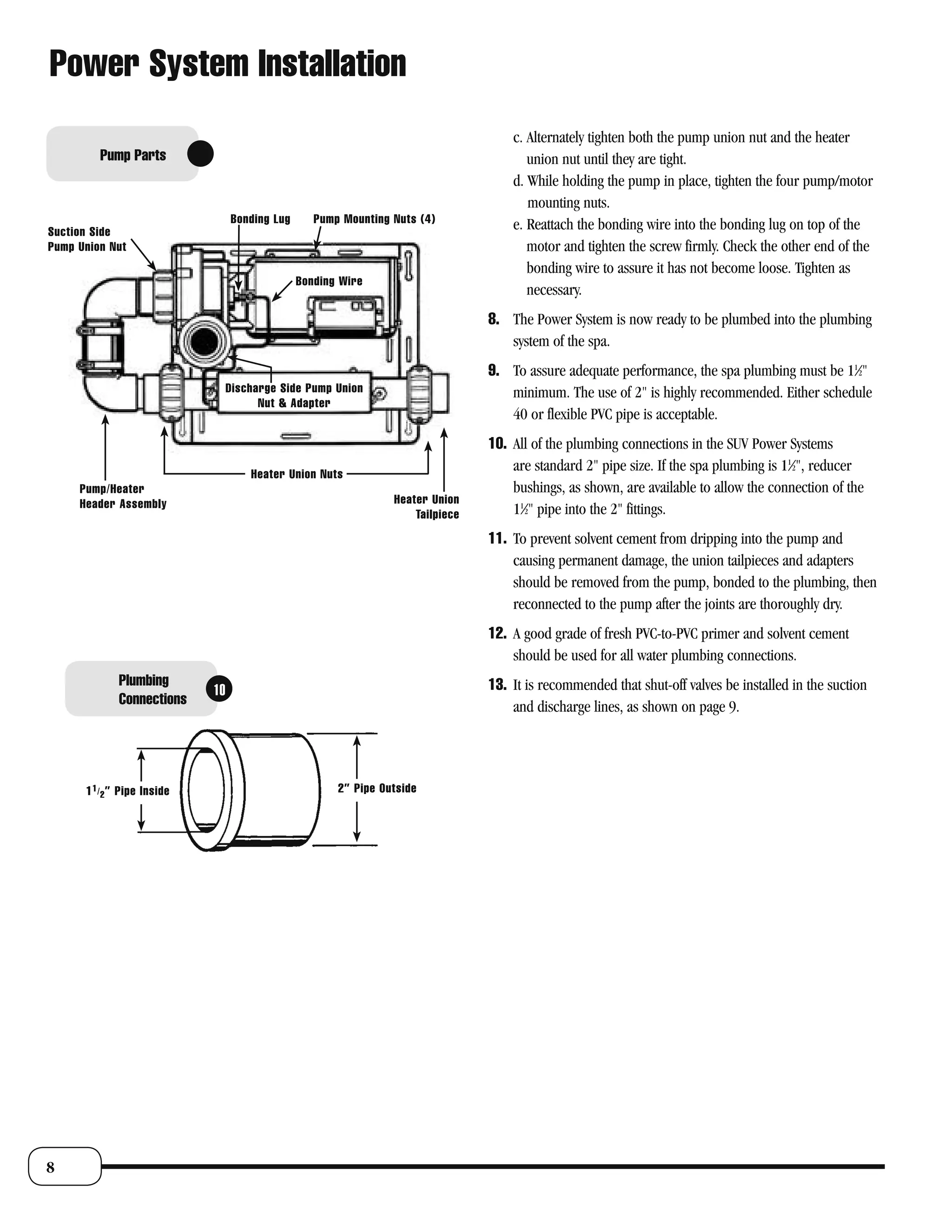
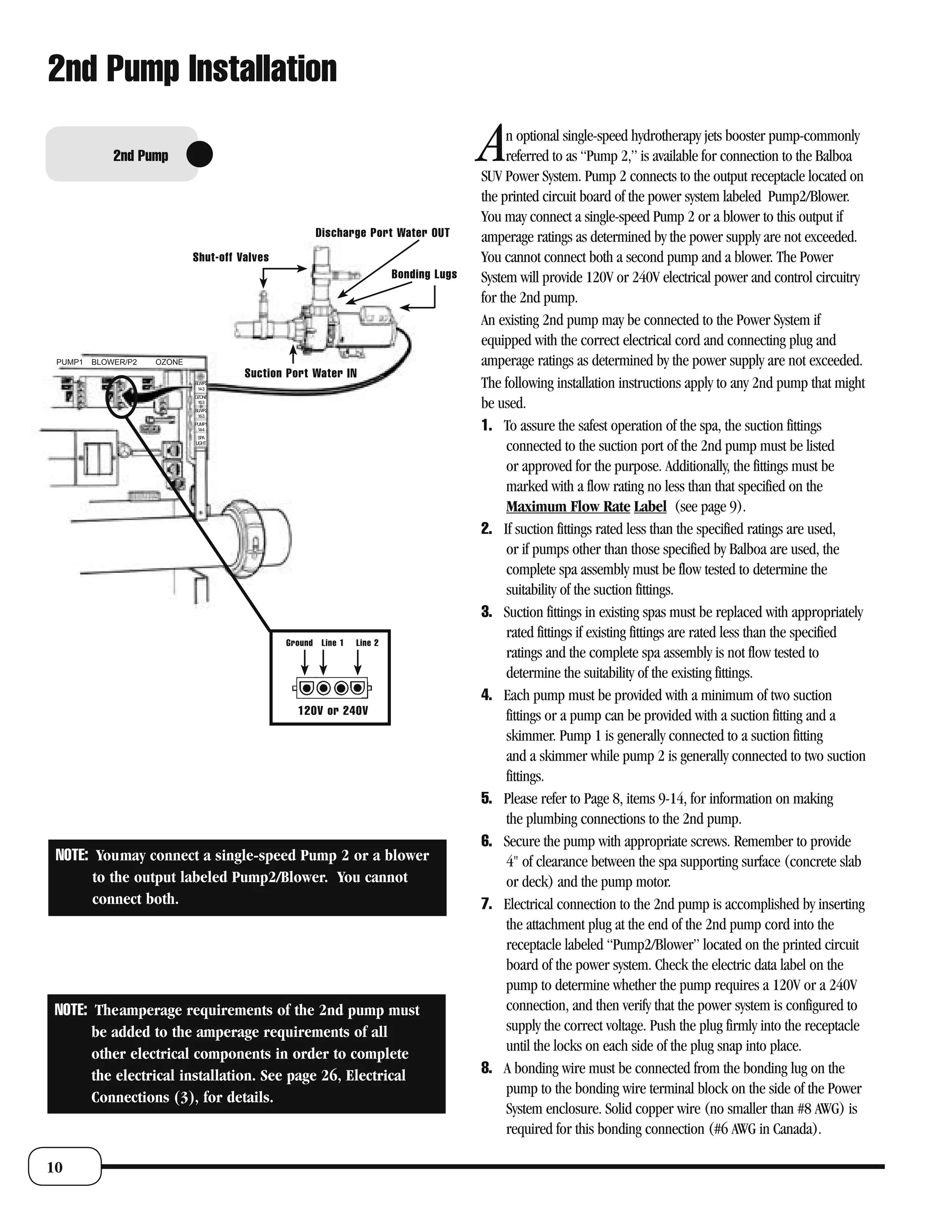
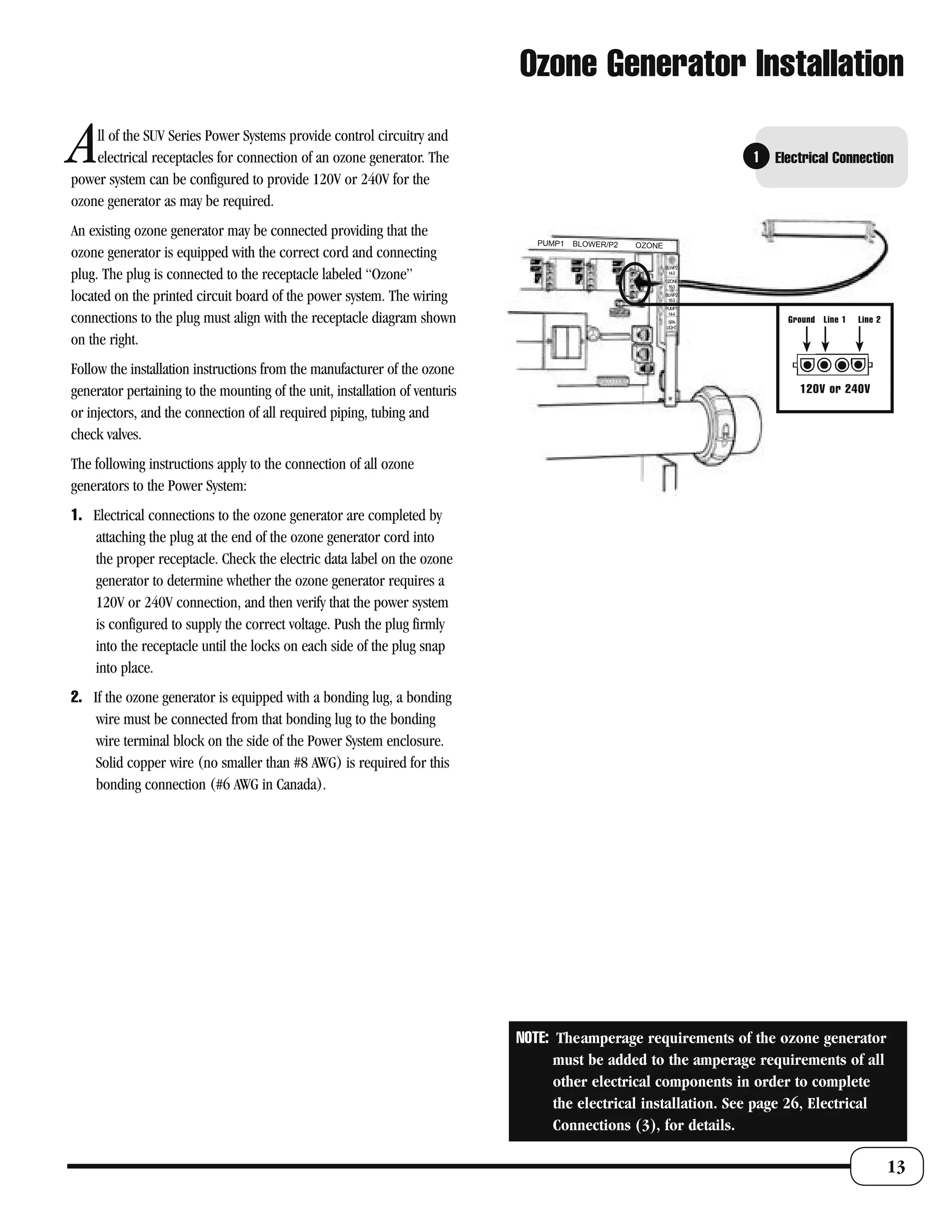
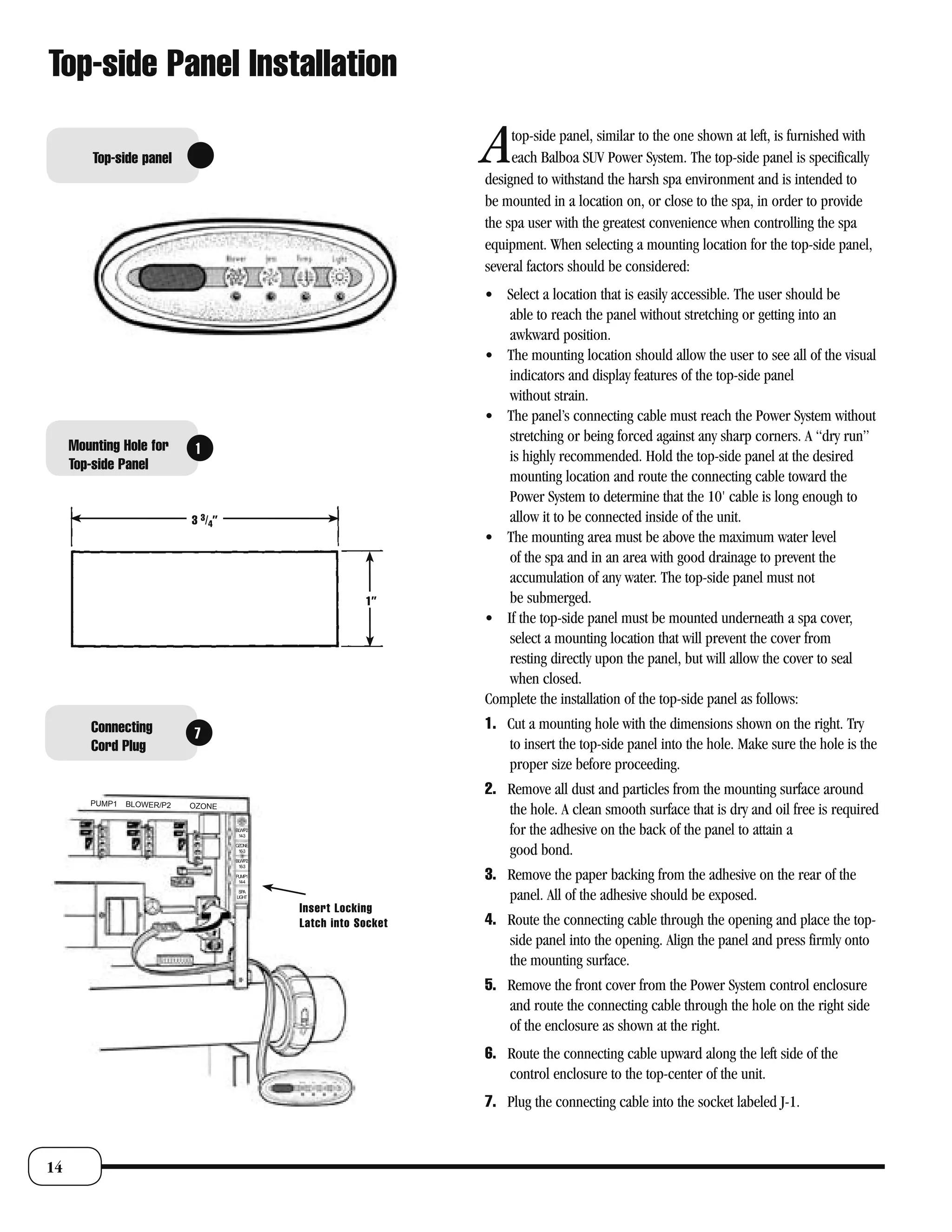
Download to read offline

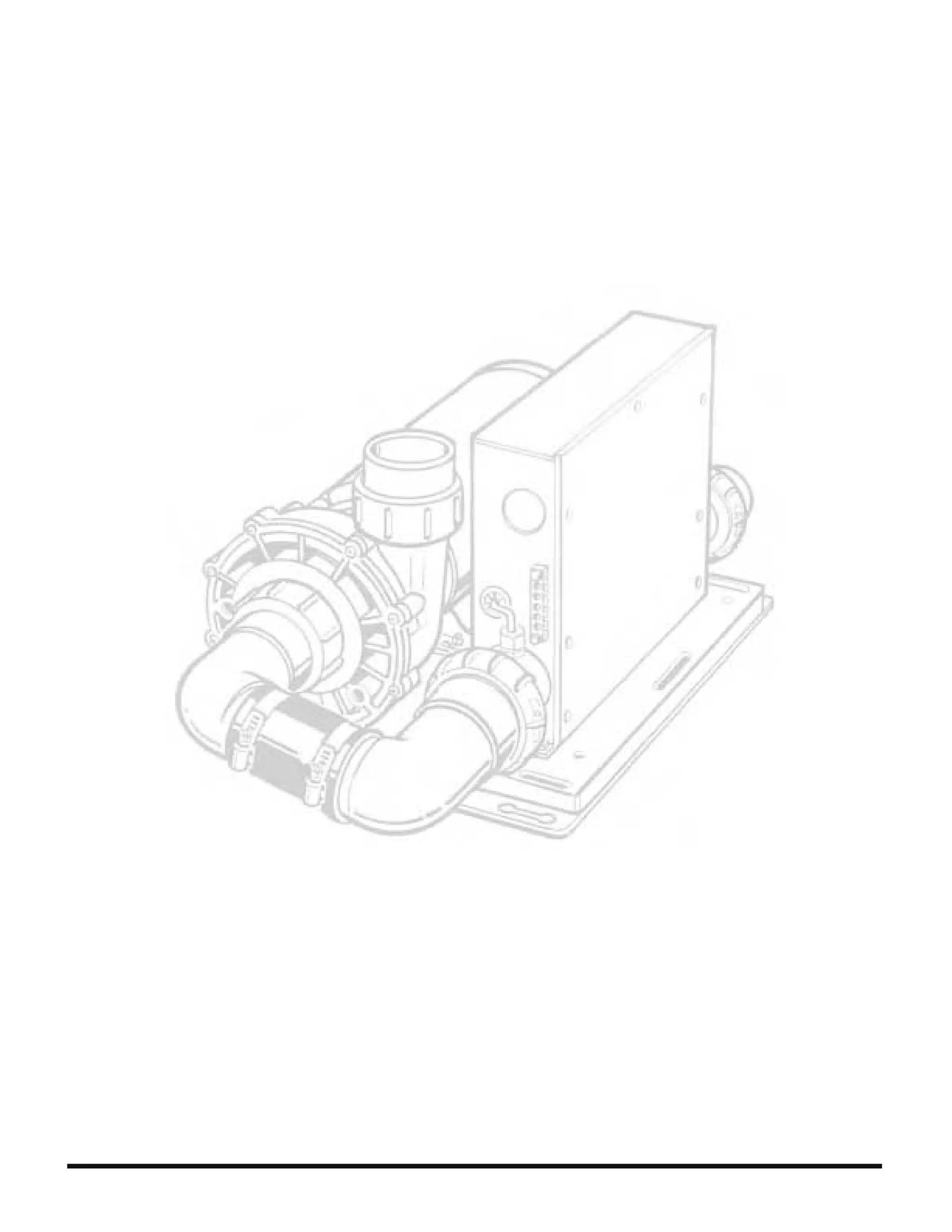


This document provides installation instructions for Balboa SUV series power systems for portable spas. It includes important safety instructions, an overview of system configurations, considerations for installation such as ventilation and drainage requirements, instructions for installing power system components like pumps and air blowers, and electrical connection details. The document also includes a warranty and technical support information.


