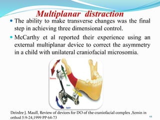
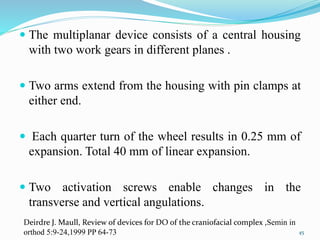
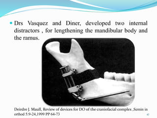
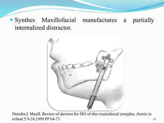
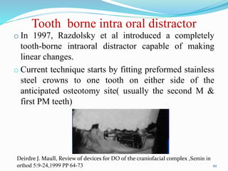
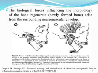
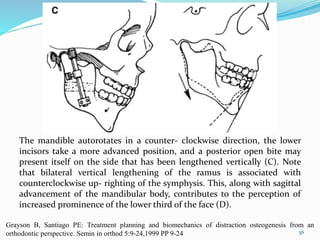
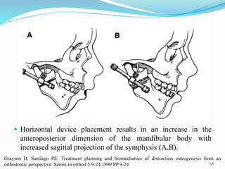
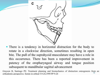
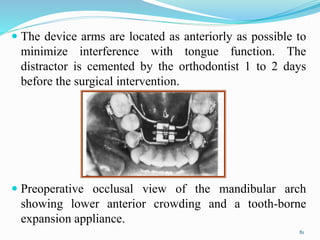
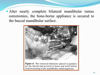
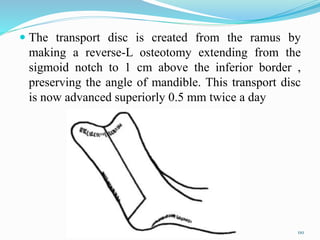
1
Contents
Introduction
History
Indications
Contraindications
Advantages
Disadvantages
Biology of distraction
Classification of distraction device
Vector of DO: biological and mechanical
2
Surgical consideration
Orthodontics consideration
Intraoral mandibular distraction osteogenesis
Midface distraction
Combined maxillary & mandibular distraction
osteogenesis
Transport distraction
Conclusion
References
3
Introduction
 Distraction osteogenesis of the craniofacial skeleton
has become increasingly popular as an alternative to
many conventional orthognathic surgical procedures.
For patients with mild to severe abnormalities of the
craniofacial skeleton, distraction techniques have
increased the number of treatment alternatives.
 Distraction osteogenesis is a biological process of new
bone formation between vascularised margins of
bone segments when they are gradually separated by
an incremental traction.
Grayson B, Santiago PE: Treatment planning and biomechanics of distraction osteogenesis from an
orthodontic perspective. Semin in orthod 5:9-24,1999 PP 9-24
Kharbanda OP, Orthodontics diagnosis and management of malocclusion and dentofacial deformities, 2nd
edition
4
History
• In 1905 Codivilla performed first bone distraction-
femur.
• In 1927, Abbott applied this same concept to the
lengthening of a tibia.
• Rosenthal applied it in maxillofacial region. However,
because of a high complication rate that included skin
infection, tissue necrosis, and the unpredictable
reossification of the expanded bone, distraction
osteogenesis did not initially gain clinical acceptance.
McCarthy, Stelnicki and Grayson,DO of the mandible: A ten year experience, semin in orthod
,vol 5,no 1 ,march 1999, PP 3-8 5
 In 1954, Ilizarov began his work on the lower
extremity.
 He was a Russian orthopedic surgeon who began
using techniques that combined compression, tension,
and then repeat bone compression to heal fractured
long bones with segmental defects.
 Based on his work in these patients, he pioneered the
radical concept that bone generation could be initiated
by the piezoelectric effect of tension , rather than
compression.
 Ten to 15 year later, he expanded his technique to
include the treatment of shortened lower extremities.
McCarthy, Stelnicki and Grayson,DO of the mandible: A ten year experience, semin in orthod
,vol 5,no 1 ,march 1999 ,PP 3-8 6
 Distraction osteogenesis remained a long-bone treatment
till 1972, Snyder et al used a Swanson external fixator
to lengthen a canine mandible.
 He surgically shortened one side of the mandible by
removing a 1.5 cm segment and then allowed the bone
to heal.
 This created a large crossbite that was surgically
corrected 10 weeks later by attaching an external fixator,
performing an osteotomy, and then slowly expanding
the device until the crossbite was normalized.
7
McCarthy, Stelnicki and Grayson, DO of the mandible: A ten year experience, semin in orthod
,Vol 5 ,no 1 ,march 1999 ,PP 3-8
 In 1975, Bell & Epker Described a technique of rapid
palatal expansion to increase the maxillary width in
cases of transverse deficiency, using a Haas appliance.
 In 1976 Michieli and Miotti reproduced Snyder's work,
using an intraoral device.
 In 1984, Kutsevliak and Sukachev took the experiment
a step further by lengthening a normal canine mandible
1.2 cm using the Ilizarov principles.
8
Guerrero et al Intraoral mandibular DO, semin in orthod ,vol 5,no 1 ,march 1999: PP 35-40
McCarthy, Stelnicki and Grayson,DO of the mandible: A ten year experience, semin in orthod
,vol 5,no 1 ,march 1999, PP 3-8
 In,1989 Joseph McCarthy performed the first distraction
of the human mandible.
 Michieli and Miotti applied in Italy to increase
mandibular length by 15mm at the rate of 0.5mm/day
followed by 40 days of fixation.
 In 1990, a study by Karp et al confirmed the feasibility
of mandibular lengthening by distraction in the canine
mandible.
9
McCarthy, Stelnicki and Grayson, DO of the mandible: A ten year experience, semin in orthod
,Vol 5 ,no 1 ,march 1999 ,PP 3-8
In, 1993 First mid-face distraction with buried devices
was performed by Steven R. Cohen.
In 1993 Rachmiel et al achieved maxillary
advancement in adult sheep followed by Polley et al n
1997.
Later in 1994 & Early 1995 – First case of Multi-
directional Midface distraction.
In 1996 Chin & Toth – LeFort III advancement with
gradual distraction using internal devices.
10
Steven R cohen , midface distraction, semin in orthod ,Vol 5 ,no 1 ,march 1999 ,PP 52-58
 In late 90s ( 1998 ) Liou & Huang performed rapid
canine retraction using distraction of periodontal
ligament.
 This was followed by a series of articles by Iseri &
Kisnisci who used dentoalveolar distraction for canine
retaction.
11
Steven R cohen , midface distraction, semin in orthod ,Vol 5 ,no 1 ,march 1999 ,PP 52-58
Indications
• Unilateral & Bilateral craniofacial microsomia
• Developmental micrognathia
• Treacher Collins syndrome, Pierre Robin syndrome
and Nager's syndrome
• Midface hypoplasia (craniofacial synostosis
syndromes)
• Transport distraction has been shown to be a useful
technique for the regeneration (Newly forming bone)
of the mandibular condyle
12
Grayson B, Santiago PE: Treatment planning and biomechanics of distraction osteogenesis from an
orthodontic perspective. Semin in orthod 5:9-24,1999 PP 9-24
• To correct mild skeletal Class II
• To expand the mandibular symphysis to skeletally
Correct lower anterior crowding.
• Condylar hypopolasia
• TMJ Ankylosis
• Posttraumatic growth disturbance
• Aid for ridge augmentation
• Recently for rapid canine retraction
13
Grayson B, Santiago PE: Treatment planning and biomechanics of distraction osteogenesis from an
orthodontic perspective. Semin in orthod 5:9-24,1999 PP 9-24
Contraindications
 Poor nutrition and lack of sift tissue
 Inadequate bone stock as in neonates
 Geriatric patients due to decreased number of
mesenchymal stem cells and repair
 Irradiated bone
 Osteoporotic bone
 Any systemic disease which effects bone metabolism
or contraindicated general anesthesia.
14
Kharbanda OP, Orthodontics diagnosis and management of malocclusion and dentofacial deformities, 2nd
edition
Advantages
 Need for orthognathic surgery is minimised and so are
the complication associated with orthognathic surgery.
 Shorter hospital stay
 Less likely hood of nerve injury
 Reduced need for intermaxillary fixation
 Reduced postoperative pain and swelling
 Less likelihood of idiopathic condylar resorption
• Greater range of maxillary advancement is possible.
15
Kharbanda OP, Orthodontics diagnosis and management of malocclusion and dentofacial deformities, 2nd
edition
• Cleft patients with maxillary hypoplasia distraction
process is less likely to adversely affect the speech.
• Greater range of mandibular advancement is possible
• New bone formed via distraction osteogenesis is more
native and permits orthodontic tooth movement.
• Allows complete bone sculpting i.e. changing the shape
and form of bones to maximise the 3D structural,
functional and aesthetic needs of the patient.
16
Kharbanda OP, Orthodontics diagnosis and management of malocclusion and dentofacial deformities, 2nd
edition
Disadvantages
 Poor 3D control on the segments with current distractor
device. The 3D distractor are being constantly modified
for desired results.
 Daily manipulation of Corticotomy one or several times a
day could give rise to pain.
 Difficult access for the orthodontist during distraction and
consolidation stages as the distractor could obscure the
buccal segments.
 Difficult plaque control
17
Kharbanda OP, Orthodontics diagnosis and management of malocclusion and dentofacial deformities, 2nd
edition
 Damage to TMJ due to incorrect vector orientation
 Technique sensitive surgery
 Equipment sensitive surgery
 High cost of distraction appliance
 Need for second surgery to remove distraction device
18
Kharbanda OP, Orthodontics diagnosis and management of malocclusion and dentofacial deformities, 2nd
edition
Biology of distraction
 Distraction as a technique is divided into two
categories, depending on the anatomic site.
 The predominant method of distraction in
maxillofacial applications is callotasis, or distraction
of the healing callus between bone fragment after a
Corticotomy or osteotomy.
19
Proffit, White, Sarver: Contemporary treatment of dentofacial deformity
 Ilizavrov’s “ law of tension stress”
Steady traction is applied to bone fragments after a
Corticotomy or osteotomy, the bone can be lengthened
by the formation of new bone at the surgical site, and it
is the healing callus that actually gives rise to the
regenerate bone
20
Proffit, White, Sarver: Contemporary treatment of dentofacial deformity
Phase of distraction osteogenesis
 Clinically, Distraction osteogenesis consists of five sequential
periods:
(1) Osteotomy
(2) Latency, the duration from bone division to the onset of traction;
(3) Distraction, the time when gradual traction is applied and
distraction regenerate is formed;
(4) Consolidation, the period that allows maturation and
corticalization of the regenerate after traction forces are
discontinued and
(5) Remodeling which extends from the initial application of full
functional loading to the completion of regenerate bone remodeling.
21
Proffit, White, Sarver: Contemporary treatment of dentofacial deformity
Osteotomy phase
 Surgical sectioning of the bone
 Osteotomy for DO should aim for maximum
preservation of periosteum and endosteum to maintain
an intact blood supply, good venous flow and viable
source of cell required in order to initiate and
perpetuate the distraction osteogenesis process.
22
Kharbanda OP, Orthodontics diagnosis and management of malocclusion and dentofacial deformities, 2nd
edition
 Traditionally fracture healing has been described as
consisting of six stages or phases
(1) Impact,
(2) Induction,
(3) Inflammation,
(4) Soft callus,
(5) Hard callus, and
(6) Remodeling
23Harsh mohan , textbook of pathology, 6 th edition
24
Latency phase
 It is characterised by initial inflammation followed by
formation of soft callus, hard callus and calcification
leading to bony union.
 If distraction is begun too early, the result is decreased
bone formation, often with cartilaginous elements
present and decreased mechanical strength of the newly
created bone.
 If distraction is begun too long(i.e, if hard callus
formation has begun) the distraction device may be
unable to further separate the bone segments.
25
Proffit, White, Sarver: Contemporary treatment of dentofacial deformity
 The soft tissue callus phase begins 3 to 7 days after
injury and lasts 2 to 3 weeks; this time frame set the
boundaries of latency period.
 Distraction in the maxillofacial skeleton has been
reported with immediate activation and with latency
phases of up to 12 day.
26
Proffit, White, Sarver: Contemporary treatment of dentofacial deformity
Distraction phase
 After latency period , tension is placed on the bony
segment by activating the appliance.
27Proffit, White, Sarver: Contemporary treatment of dentofacial deformity
 Two important variable in the activation
1. Rate: Amount of distraction per day
2. Rhythm: How frequently the devices is activated
Rate 1.0 mm per day
Small risk of pre mature consolidation
Great undue stress on soft callus resulting in
thinning of all dimension in midportion of regenerate
and an “ hourglass” at distraction site
28
Proffit, White, Sarver: Contemporary treatment of dentofacial deformity
Rhythm
Continuous application of distraction force is ideal
Clinically, application of the distraction is best
performed by activating the device twice a day(0.5
mm twice a day)
If the patient experiences discomfort ,then the rhythm
should be altered to allow for a smaller incremental
application(0.25 mm for four times a day)
29
Proffit, White, Sarver: Contemporary treatment of dentofacial deformity
Radiographic and schematic drawing demonstrating five zonal structure
of distraction regenerate. Radiolucent fibrous interzone(FZ); Radiodense
mineralizing zone(MZ); Radiolucent zone of remodeling(RZ); Residual
host bone segments(RHBS). 30
Consolidation phase
 The consolidation period is that time between
cessation of traction forces and removal of the
distraction device.
 This period represents the time required for complete
mineralization of the distraction regenerate.
 After distraction ceases, the fibrous interzone
gradually ossifies and one distinct zone of fiber bone
completely bridges the gap.
31
Proffit, White, Sarver: Contemporary treatment of dentofacial deformity
Radiograph and schematic drawing demonstrating structure of
distraction regenerate during consolidation period. Radiolucent zone of
remodeling(RZ) adjacent to the residual host bone segments(RHBS) and
divided by the mineralization zone (MZ).
32
 The total amount of bone formation seen in different
type of regenerate varies, but the final percentage of
trabecular bone increased from the end of distraction
through 8 weeks of consolidation.
 Mineralization began at the host bone margins at the end
of distraction and progressively increased up to the
fourth week of consolidation, at which time it remained
stable for the following 2 weeks. This decreased slightly
from 6 to 8 weeks of consolidation, as remodeling
became the predominant activity of the regenerate.
33
Proffit, White, Sarver: Contemporary treatment of dentofacial deformity
Remodelling
 The remodeling period is the period from the
application of full functional loading to the complete
remodeling of the newly formed bone.
 It takes a year or more before the structure of newly
formed bony tissue is comparable to that of the
preexisting bone.
 Generally the regenerated segments of bone show a
relatively low mineral content and radiodensity.
34
Kharbanda OP, Orthodontics diagnosis and management of malocclusion and dentofacial deformities, 2nd
edition
Schematic drawing demonstrating structures of distraction regenerate during
remodeling period. Gradual corticalization of the remodeling zone (RZ) with
formation of medullary canal (MC)is seen. RHBS, Residual host bone
segment; CB, Cortical Bone.
35
Classification of distraction device
36
Distraction appliances of the maxillofacial region can
be divided into:
Extra-oral appliances
Unidirectional devices
Bi-directional devices
Multidirectional devices
Intra-oral devices
Tooth-borne devices
Tissue-borne devices
Hybrid (tooth and tissue borne) devices
37
Deirdre J. Maull, Review of devices for DO of the craniofacial complex ,Semin in
orthod 5:9-24,1999 PP 64-73
External unidirectional distraction
devices
 In 1992, McCarthy et al introduced an external
unidirectional distractor to successfully lengthen the
mandible unilaterally and bilaterally.
 The amount of distraction varied from 18 mm to 24
mm .
 The distractor consisted of a single calibrated rod with
two clamps .
 Each clamp holds two 2 mm half pins that are placed
on either side of the osteotomy.
38
Deirdre J. Maull, Review of devices for DO of the craniofacial complex ,Semin in
orthod 5:9-24,1999 PP 64-73
HOW IT WORK ?
 Approximately 20 mm to 24 mm of bone stock
posterior to the last tooth bud is necessary to place this
device.
 By turning the bolt at the end of the rod ,the distance
between the clamps can be changed to provide
expansion or compression at the level of the bone.
39
Deirdre J. Maull, Review of devices for DO of the craniofacial complex ,Semin in
orthod 5:9-24,1999 PP 64-73
Molina Distractors
 Ortiz & Molina modified the Ilizarov technique by
performing an incomplete Corticotomy.
 They left the internal cortical plate and the cancellous
layer intact & used a semi rigid external distractor.
 This has the capability to further exploit the secondary
soft tissue expansion associated with osteodistraction.
 Molina distractors are unidirectional, changes in three
dimensions have been documented.
40
Deirdre J. Maull, Review of devices for DO of the craniofacial complex ,Semin in
orthod 5:9-24,1999 PP 64-73
Disadvantages
 Scarring as a result of pins dragging through the skin
during expansion
 Difficulty predicting the direction in which the
distraction would proceed
 Inability to change direction once distraction process
had begun
41
Deirdre J. Maull, Review of devices for DO of the craniofacial complex ,Semin in
orthod 5:9-24,1999 PP 64-73
External bidirectional distraction
 A bidirectional distraction appliance provides an
additional degree of freedom over the unidirectional
device.
 Klein & Howaldt developed an external bi-directional
device capable of achieving controlled changes in
angulation.
 The device consists of two geared arms 5 cm in length
connected to a middle screw that enables the arms to be
moved up or down to change angulations.
42
Deirdre J. Maull, Review of devices for DO of the craniofacial complex ,Semin in
orthod 5:9-24,1999 PP 64-73
 Molina offers an external bi-directional distractor
based on same principles as his unidirectional device.
43
Deirdre J. Maull, Review of devices for DO of the craniofacial complex ,Semin in
orthod 5:9-24,1999 PP 64-73
Multiplanar distraction
 The ability to make transverse changes was the final
step in achieving three dimensional control.
 McCarthy et al reported their experience using an
external multiplanar device to correct the asymmetry
in a child with unilateral craniofacial microsomia.
44
Deirdre J. Maull, Review of devices for DO of the craniofacial complex ,Semin in
orthod 5:9-24,1999 PP 64-73
 The multiplanar device consists of a central housing
with two work gears in different planes .
 Two arms extend from the housing with pin clamps at
either end.
 Each quarter turn of the wheel results in 0.25 mm of
expansion. Total 40 mm of linear expansion.
 Two activation screws enable changes in the
transverse and vertical angulations.
45
Deirdre J. Maull, Review of devices for DO of the craniofacial complex ,Semin in
orthod 5:9-24,1999 PP 64-73
Internal distractors
 In 1995, McCarthy et al introduced an intraoral
distraction appliance tested on the canine model.
 After osteotomy , the device was placed on the buccal
surface of the mandible and the lengthening rod was
extended into the buccal vestibule.
 A drawback of the appliance was that it could only
accommodate 20 mm of expansion.
46
Deirdre J. Maull, Review of devices for DO of the craniofacial complex ,Semin in
orthod 5:9-24,1999 PP 64-73
 Drs Vasquez and Diner, developed two internal
distractors , for lengthening the mandibular body and
the ramus.
47
Deirdre J. Maull, Review of devices for DO of the craniofacial complex ,Semin in
orthod 5:9-24,1999 PP 64-73
 Synthes Maxillofacial manufactures a partially
internalized distractor.
48
Deirdre J. Maull, Review of devices for DO of the craniofacial complex ,Semin in
orthod 5:9-24,1999 PP 64-73
Tooth borne intra oral distractor
o In 1997, Razdolsky et al introduced a completely
tooth-borne intraoral distractor capable of making
linear changes.
o Current technique starts by fitting preformed stainless
steel crowns to one tooth on either side of the
anticipated osteotomy site( usually the second M &
first PM teeth)
49
Deirdre J. Maull, Review of devices for DO of the craniofacial complex ,Semin in
orthod 5:9-24,1999 PP 64-73
Vector of DO: Biological and
Mechanical
 The biological and mechanical forces that shape the
regenerate (the newly formed bone during the active
period of distraction osteogenesis) are key elements in
determining appliance position. The desired
mandibular change in shape and function can be
achieved by selecting and controlling the force vectors
that operate during active distraction.
50
Grayson B, Santiago PE: Treatment planning and biomechanics of distraction osteogenesis from an
orthodontic perspective. Semin in orthod 5:9-24,1999 PP 9-24
 The biological forces influencing the morphology
of the bone regenerate (newly formed bone) arise
from the surrounding neuromuscular envelop.
51
Grayson B, Santiago PE: Treatment planning and biomechanics of distraction osteogenesis from an
orthodontic perspective. Semin in orthod 5:9-24,1999 PP 9-24
 The mechanical forces under the clinician's control
originate from activation of the distraction devices,
their specific orientation to skeletal anatomy, the
application of intermaxillary elastics during the active
phase of distraction, and the intercuspation of the
dentition.
 It is important to note that the position of the device is
best described in relation to the long axis of the
mandibular body.
52
Grayson B, Santiago PE: Treatment planning and biomechanics of distraction osteogenesis from an
orthodontic perspective. Semin in orthod 5:9-24,1999 PP 9-24
 Vectors of distraction. Straight lines
indicate the long axis of the device.
Vertical (A), horizontal (B), and
oblique (C). The line represents the
long axis of the device in relation to
the long axis of the mandibular body.
In this planning method, the authors
do not orient the device in relation to
the posterior border of the ramus or
the inferior border of the mandible
because of the variability in
morphology of these borders.
53
Grayson B, Santiago PE: Treatment planning and biomechanics of distraction
osteogenesis from an orthodontic perspective. Semin in orthod 5:9-24,1999
PP 9-24
Vertical device placement
 Vertical device placement results in an increase in the
vertical dimension of the mandibular ramus. During
activation, a change occurs in appliance orientation
that appears to be caused by the nonlinear molding
effect of the neuromusculature on the regenerate as it
is formed.
 The mandible autorotates in a counterclockwise
direction, and the lower incisors take a more advanced
position. A posterior open bite may occur on the side
that has undergone vertical distraction in the ramus
54
Grayson B, Santiago PE: Treatment planning and biomechanics of distraction osteogenesis from an
orthodontic perspective. Semin in orthod 5:9-24,1999 PP 9-24
The device placed vertically in the mandibular ramus
before activation (A). Activation of the device results in
an increase in the vertical height of the ramus. Note the
separation between the maxillary and mandibular
dentition before closure of the mandible (B).
55
Grayson B, Santiago PE: Treatment planning and biomechanics of distraction osteogenesis from an
orthodontic perspective. Semin in orthod 5:9-24,1999 PP 9-24
The mandible autorotates in a counter- clockwise direction, the lower
incisors take a more advanced position, and a posterior open bite may
present itself on the side that has been lengthened vertically (C). Note
that bilateral vertical lengthening of the ramus is associated with
counterclockwise up- righting of the symphysis. This, along with sagittal
advancement of the mandibular body, contributes to the perception of
increased prominence of the lower third of the face (D).
56
Grayson B, Santiago PE: Treatment planning and biomechanics of distraction osteogenesis from an
orthodontic perspective. Semin in orthod 5:9-24,1999 PP 9-24
Horizontal device placement
 The most efficient approach for achieving sagittal
projection of the mandibular body and symphysis is by
placement of the distraction device in a horizontal
position in relation to the mandibular body.
57
Grayson B, Santiago PE: Treatment planning and biomechanics of distraction osteogenesis from an
orthodontic perspective. Semin in orthod 5:9-24,1999 PP 9-24
 Horizontal device placement results in an increase in the
anteroposterior dimension of the mandibular body with
increased sagittal projection of the symphysis (A,B).
58
Grayson B, Santiago PE: Treatment planning and biomechanics of distraction osteogenesis from an
orthodontic perspective. Semin in orthod 5:9-24,1999 PP 9-24
 There is a tendency in horizontal distraction for the body to
rotate in a clockwise direction, sometimes resulting in open
bite. The pull of the suprahyoid musculature may have a role in
this occurrence. There has been a reported improvement in
patency of the oropharyngeal airway and tongue position
subsequent to mandibular sagittal advancement
59
Grayson B, Santiago PE: Treatment planning and biomechanics of distraction osteogenesis from an
orthodontic perspective. Semin in orthod 5:9-24,1999 PP 9-24
Oblique device placement
 Oblique device placement results in an increase in
both the vertical and horizontal dimensions of the
ramus and body. The effect of oblique device
placement is a combination of the vertical and
horizontal changes previously described. Overjet and
both ramal and body size deficiency may be addressed
by oblique device placement.
60
Grayson B, Santiago PE: Treatment planning and biomechanics of distraction osteogenesis from an
orthodontic perspective. Semin in orthod 5:9-24,1999 PP 9-240
Surgical consideration
 The surgical plan must include selection of anatomical
site, design of osteotomy, locations of distraction
holding device and orthodontics before during and
after distraction.
 Positioned along the planned vector of distraction.
 Prophylactic antibiotics.
 Performed under nasoendotracheal GA.
61
Kharbanda OP, Orthodontics diagnosis and management of malocclusion and dentofacial deformities, 2nd
edition
 During the osteotomy procedure due care should be
taken not to violate underlying teeth, roots of teeth,
neurovascular bundle.
 In sagittal mandibular distraction, if osteotomy cuts
are placed distal to last molar, posterior/lateral open
bite would be observed during distraction; if mesial
to last molar an anterior open bite is expected.
 BSSO can also be considered as osteotomy design for
sagittal mandibular distraction.
62
Kharbanda OP, Orthodontics diagnosis and management of malocclusion and dentofacial deformities, 2nd
edition
 In case requiring midface advancement such as those
with operated with le fort I osteotomy of cleft lip and
palate.
 Transverse maxillary deficiency low level le fort I
osteotomy with mid palatal split is performed.
 Device is activated initially 2-3 mm
63
Kharbanda OP, Orthodontics diagnosis and management of malocclusion and dentofacial deformities, 2nd
edition
Orthodontics Consideration
 Treatment planning Following points are considered
while planning a case for distraction osteogenesis:-
1. Records
2. Treatment planning sessions joint sessions should be
organized between the orthodontist and the team of
surgeons
3. When planning mandibular advancement: nature and
type of advancement must be considered: unilateral
v/s bilateral, vector of distraction, site of distraction.
64
Kharbanda OP, Orthodontics diagnosis and management of malocclusion and dentofacial deformities, 2nd
edition
4. Maxillary advancement in hypoplasia: sagittal,
sagittal combine with transverse.
5. Maxillary advancement in CLP patients:
velopharyngeal/speech consideration.
65
Kharbanda OP, Orthodontics diagnosis and management of malocclusion and dentofacial deformities, 2nd
edition
Orthodontic treatment protocol The role of orthodontics
in treatment using distraction osteogenesis falls into
three temporal phases:
1. Predistraction treatment planning and orthodontic
preparation
2. Orthodontic/ orthopedic during distraction and
consolidation
3. Post consolidation Orthodontic/ orthopedic
management
66
Hanson and Melugin, orthodontic management of patient undergoing mandibular DO,
Semin in orthod 5:9-24,1999 PP 25-34
Pre distraction orthodontics
 Maxillary and mandibular dental arches are prepared
for distraction osteogenesis by levelling, alignment,
decompensation and correction of curve of spee.
 Teeth should be moved to ideal position relative to the
basal bone so that ideal maxillomandibular
relationship is not compromised by existing dental
compensation.
 Coordination of both maxillary and mandibular arches
followed by placement of passive rectangular
archwires with hooks for engaging inter-arch elastic
during and after distraction
67
Kharbanda OP, Orthodontics diagnosis and management of malocclusion and dentofacial deformities, 2nd
edition
 The osteotomy design, distractor device orientation,
masticatory muscles influence, occlusal interferences
and orthodontic forces during distraction and
consolidation phase govern and affect the choice of
vector of distraction.
 In case of distraction osteogenesis in children and
young adolescents future growth prediction and over
correction is recommended.
 In case of mandibular corpus/ramus distraction, three
planes i.e. occlusal plane, mandibular plane, ramus
plane can be used as guiding planes to orient the
distractor device.
68
Kharbanda OP, Orthodontics diagnosis and management of malocclusion and dentofacial deformities, 2nd
edition
 Another component of Predistraction orthodontic
treatment is the fabrication and use of distraction
stabilization appliances.
 The appliances are placed before distraction and
provide multiple opportunities for the use of interarch
elastics to control mandibular position during the
distraction, consolidation, and post consolidation
phases.
69
Hanson and Melugin, orthodontic management of patient undergoing mandibular DO,
Semin in orthod 5:9-24,1999 PP 25-34
Orthodontics during distraction and
consolidation
 Orthodontic/orthopedic treatment may include the use
of bands, brackets, distraction stabilization appliances,
elastics, headgear, maxillary expansion appliances etc.
 In pre-distraction planning, the orthodontist evaluates
and determines the desired vector based on skeletal
appraisal.
70
Hanson and Melugin, orthodontic management of patient undergoing mandibular DO,
Semin in orthod 5:9-24,1999 PP 25-34
 Four influences presumed to affect the observed
vector are:
1. The unique biomechanical characteristics of the
selected distraction device,
2. Orientation of the distraction device to the
mandibular anatomy,
3. Neuromuscular influence, and
4. Externally exerted forces.
71
Hanson and Melugin, orthodontic management of patient undergoing mandibular DO,
Semin in orthod 5:9-24,1999 PP 25-34
 If the distraction goal is pure vertical elongation of the
ramus with unilateral posterior bite opening and no
anterior movement, this is best realized when the
vector of distraction is perpendicular or acute to the
patient's occlusal plane. Placement of the device
parallel to the posterior border of the ramus or
perpendicular to the inferior border of the body is not
consistent with the goal of achieving a vertical
direction of distraction. Placement of the distraction
device parallel to the posterior border of the ramus
results in an oblique distraction vector as it relates to
the occlusion.
72
Hanson and Melugin, orthodontic management of patient undergoing mandibular DO,
Semin in orthod 5:9-24,1999 PP 25-34
 If the distraction goal is pure sagittal advancement of
the mandibular body, this is best realized when the
vector of distraction is parallel to the patient's occlusal
plane. Placement of the device parallel to the inferior
border of the mandibular body is not consistent with a
horizontal direction of distraction, as it would be
oblique to the occlusal plane If the distraction goal is
to achieve both ramus and body lengthening, an
oblique vector is used.
73
Hanson and Melugin, orthodontic management of patient undergoing mandibular DO,
Semin in orthod 5:9-24,1999 PP 25-34
 Oblique placement was defined as greater than 90° of
angulation between the occlusal plane and the long
axis of the distraction device.
 Vertical placement was defined as 90° or less of
angulation between the occlusal plane and the long
axis of the distraction device.
 The 3rd force that is presumed to affect the path of the
tooth bearing segment is generated by the
neuromuscular.
 The 4th influence that may affect the position of the
tooth bearing segment is the application of external
forces.
74
Hanson and Melugin, orthodontic management of patient undergoing mandibular DO,
Semin in orthod 5:9-24,1999 PP 25-34
Intermaxillary Elastics During Active
Distraction
 It is believed that the observed occlusal response to
elastic forces is secondary to molding of the
regenerate and dentoalveolar remodelling. Thus,
intermaxillary elastics can be used to modify the
direction of skeletal change and fine tune the occlusal
outcome of distraction.
 Intermaxillary elastics may be worn in Class II, III,
vertical, or transverse (buccolingual) directions during
the active phase of distraction.
 Anterior vertical intermaxillary elastics may be
helpful in the reduction of an anterior open bite and
may be used transversely to correct crossbite
75
Grayson B, Santiago PE: Treatment planning and biomechanics of distraction osteogenesis from an
orthodontic perspective. Semin in orthod 5:9-24,1999 PP 9-24
Intermaxillary elastics may be helpful in the reduction of an anterior
open bite and may be used transversely to correct crossbite or lateral
shift of the mandible during active distraction. In this illustration, the
mandible has shifted toward the contralateral side resulting in posterior
crossbite. The ipsilateral side shows open bite. Cross elastics combined
with a mandibular lingual stabilization arch are used to correct the
crossbite.
76
Grayson B, Santiago PE: Treatment planning and biomechanics of distraction osteogenesis from an
orthodontic perspective. Semin in orthod 5:9-24,1999 PP 9-24
Postdistarction orthodontic management
• After consolidation and removal of appliance
orthodontist has to give final finishing of occlusion.
• In the unilateral distraction cases, the orthodontist is
often confronted with a posterior open bite on the
distracted side and a crossbite on the contralateral
side.
77
Grayson B, Santiago PE: Treatment planning and biomechanics of distraction osteogenesis from an
orthodontic perspective. Semin in orthod 5:9-24,1999 PP 9-24
• The open bite may be managed with gradual
adjustment of a bite plate.
• The crossbite resulting from mandibular shift across
the midsagittal plane may be corrected by a
combination of transpalatal arches, lingual arches,
intermaxillary cross elastics, and a palatal expansion
devices.
78
Grayson B, Santiago PE: Treatment planning and biomechanics of distraction osteogenesis from an
orthodontic perspective. Semin in orthod 5:9-24,1999 PP 9-24
Intraoral Mandibular Distraction
Osteogenesis
Cesar A. Guerrero,
William H. Bell,
Gisela I. Contasti and
Aura M. Rodriguez
Semin Orthod 1999;5:35-40.
79
 Mandibular widening through distraction osteogenesis
corrects the basal bone problem by creating new bone
to accommodate the teeth, eliminating the need for
dental extraction, and offering stable results.
 Preoperative intraoral view of a patient with transverse
mandibular deficiency (A). Postoperative view after 14
mm of intraoral mandibular distraction osteogenesis to
widen the mandible. (B). 80
 The device arms are located as anteriorly as possible to
minimize interference with tongue function. The
distractor is cemented by the orthodontist 1 to 2 days
before the surgical intervention.
 Preoperative occlusal view of the mandibular arch
showing lower anterior crowding and a tooth-borne
expansion appliance.
81
 The orthodontist must provide root divergence in the
mandibular osteotomy site to ensure that sufficient
alveolar bone remains on both sides of the planned
osteotomy for the periodontal health of the dentition.
82
Intraoral Distraction Osteogenesis Protocol
 Distraction device insertion. The device is inserted 1
to 2 days before surgery.
 Osteotomy. The osteotomy is completed and the
distractor is activated 2 mm.
 Latency period. Activation of the distractor begins 7
days after surgery.
 rate of distraction. Distraction is performed at a rate
of 1 mm daily.
 Rhythm of distraction. The distraction appliance is
activated at a rhythm of once a day
83
 Orthodontic tooth movement should not begin until
removal of the distraction appliance, 8 to 12 weeks
after surgery.
 Once the desired amount of distraction is achieved, a
cosmetic acrylic tooth is ligated to the orthodontic
arch wire at the interdental gap.
 After the stabilization (consolidation) period (8 to 12
weeks), active orthodontic movement of the teeth with
light progressive forces is reestablished. The
mesiodistal width of the acrylic tooth is reduced while
the teeth adjacent to the osteotomy site are moved
with orthodontic forces to close the interdental gap .
84
 Alter nearly complete bilateral mandibular ramus
osteotomies, the bone-borne appliance is secured to
the buccal mandibular surface .
85
86
Midface Distraction
Steven R. Cohen
(Semin Orthod 1999;5:52-58.
87
 In Munich, Muhlbauer conducted a series of Le Fort
III and monobloc distractions in a small group of
patients with Apert's syndrome.
 In 1997, in the Journal of Craniofacial Surgery,
Polley and Figueroa discussed the management of
severe maxillary deficiency in childhood and
adolescence, performing distraction osteogenesis with
an external adjustable, rigid distraction device.
 The Modular Internal Distraction (MID) system
allows the surgeon to fabricate custom internal
distraction de- vices for virtually any region of the
craniofacial skeleton.
88
 The first generation system contains expansion screws
capable of 15 nun and 30 mm of distraction.
 Depending on the distraction site and osteotomy, any
configuration of titanium plates can be attached to the
distraction screw to permit uniplanar and possibly
biplanar internal distraction.
 A flexible activation cable is brought out through a
distant, inconspicuous stab wound in the hair behind
the ear.
89
Clinical indication
 Patients with cleft lip and palate and severe midface
retrusion at the age of 6 years typically will not be
corrected by standard orthodontic therapy alone.
 When severe deformities are present at the age of 6
years, distraction osteogenesis can be used in
combination with early rapid palatal expansion to
correct both sagittal and transverse maxillary
deficiencies.
 Internal distraction osteogenesis performed in children
with cleft lip and palate as young as 6 years of age.
90
 Patients with syndromic craniosynostosis have
traditionally undergone fronto-orbital advancement alone
at 4 to 9 months of age.
 The majority of treatment protocols address the midfacial
hypoplasia between 4 and 7 years of age, using either
monobloc or Le Fort III osteotomies.
 When hypertelorbitism is present, intracranial or
subcranial facial bipartition is per- formed. Because of
mandibular growth, Class III malocclusion recurs in early
to later adolescence, necessitating orthognathic surgery
and occasionally repeated Le Fort III osteotomy.
91
 Other possible indications for midface distraction
include:
(1) correction of maxillary canting in hemifacial
microsomia and other asymmetry malformations;
(2) apnea with associated midface retrusion;
(3) Treacher Collins syndrome for zygomatic
advancement; and
(4) midface retrusion of any cause, depending on severity.
92
Timing of surgery
 In children with syndromic craniosynostosis and
severe midface retrusion, monobloc osteotomies can
be performed safely at younger than 1 year of age.
 In children age 4 to 7 years undergoing monobloc or
Le Fort III subcranial osteotomy, operative morbidity
is also reduced.
 In children requiring midface distraction for
obstructive sleep apnea to correct retropalatal
obstruction, midface distraction may be necessary in
concert with mandibular distraction to provide
simultaneous correction of retropalatal and retro
lingual obstruction. 93
Surgical techniques
Le-fort I distraction:-
The Le Fort I osteotomy is performed in a stair-step
fashion to provide adequate posterior bone for
attachment of the distraction device.
94
 Because the MID system provides flexibility, the
types of titanium plates selected for posterior and
anterior distraction vary.
 To maintain a direct sagittal distraction vector, the
anterior plate is generally bent with a step.
 It is necessary to make a complete osteotomy and,
therefore, the osteotomy is kept just below the level of
the inferior orbital foramen and nerve.
95
Le-fort III distraction:-
A standard Le Fort III osteotomy is performed in
younger children who are at risk for fracturing the
zygomatic-maxillary suture region, the anterior plate is
configured and rigidly fixed after the osteotomy, but
before down-fracture.
Le Fort III osteotomy with
plates secured to the malar
eminence and the lateral
orbital rim with the MID
distraction appliance in place.
96
 The posterior plate is stabilized to the temporal bone
underneath the temporal muscle.
 A 30-mm distraction frame is chosen and attached to
the anterior and posterior plates.
 In Le Fort III osteotomy, typically 2 mm to 4 mm of
distraction is performed in the operating room.
 Distraction is then begun on the fifth postoperative
day at a rate of 1 mm per day.
97
 Once the appropriate porion to orbitale distance has
been reached and/or mild enophthalmos has been
produced with overcorrection of the malocclusion,
distraction is stopped and the distraction gap allowed
to consolidate over a period of 2 months.
 Dental elastics are used to correct occlusal
abnormalities.
98
Monobloc distraction
 Monobloc distraction is applicable in children aged
younger than 1 year, but can be used in any age group.
 Monobloc osteotomy
consists of a Le Fort III and
a frontal bone osteotomy.
The distraction device is
secured posteriorly to the
temporal bone and anteriorly
to the Zygoma and lateral
orbital rim. The flexible
activating cable exits the
skin above the ear.
99
 A 3 1/2-year-old boy with Apert's syndrome, hypertelorbitism, and flat
facial plane (A). Preoperative lateral photograph (B). Depiction of operative
technique (C). Note facial bipartition was performed simultaneously with
distraction. The bipartition is stabilized with rigid fixation, and the
distraction device is applied. Artist depiction of distraction devices in
position (D). Postoperative frontal photograph 6 months after devices were
removed (E). Postoperative lateral photograph 6 months after devices were
removed and 25 mm of distraction (F). 100
COMBINED MAXILLARY &
MANDIBULAR DISTRACTION
OSTEOGENESIS
Fernando Molina
Semin Orthod 1999;5:41-45.
101
 Mandibular elongation by gradual distraction in
patients with hemifacial microsomia is a simple and
effective procedure to correct facial asymmetry.
 The changes in mandibular dimension result in
changes in dental occlusion.
 These are minimal in children because of the rapid
growth of the maxilla and can be corrected easily with
minor orthodontic treatment.
102
 Mandibular distraction in adults with hemifacial
microsomia produces good aesthetic results but leaves
the patient with a severe alteration in the occlusion
requiring complex orthodontic treatment over a long
period of time.
 To avoid this problem, an incomplete Le Fort I
osteotomy is performed simultaneously with the
mandibular Corticotomy.
 Intermaxillary fixation is placed on the fifth
postoperative day, and distraction is initiated.
103
 After distraction, both the maxillary and mandibular
occlusal planes become horizontal, and facial
asymmetry is corrected.
 There is a reduction in treatment time and cost when
compared with the protocol of mandibular distraction
followed by passive bite plate guiding the eruption of
the maxillary posterior occlusal plane
104
 The softer (flexible) distraction screw used in this
system allows medial rotation of the mandible, which
closely imitates the normal development of a growing
mandible.
 The chin is always medialized by the distraction but,
in adults, it is not always possible to align it precisely
under the midsagittal plane.
 At the present time, the author believes that
simultaneous maxillomandibular distraction is the
procedure of choice in patients with moderate and
severe hemifacial microsomia who are older than 12
years of age.
105
Reconstruction of a Neocondyle Using
Transport Distraction Osteogenesis
Suzanne U. Stucki-McCormick,
Robert M. Fox, and
Ronald D. Mizrahi
Semin Orthod 1999;5:59- 63.
106
 The process of slow bone expansion by distraction
osteogenesis in conjunction with functional
remodeling can also be used for the reconstruction of
a neomandible and neocondyle. This is the technique
of transport distraction osteogenesis.
 Transport distraction osteogenesis is the technique of
regenerating bone and soft tissues in a discontinuity
defect.
 Osteotomy is made 1.5 cm from the end of the distal
stump of bone adjacent to the discontinuity defect
creating a transport disc.
107
 Using a distraction device, the transport disc is
advanced through the soft tissue discontinuity defect,
creating new bone within the distraction gap, as the
leading edge becomes enveloped by a
fibrocartilagenous cap.
108
 The mandible there- fore acts as the bony template for
reconstruction such that the neomandible created from
the distraction process has the same size and shape as
the native mandible covered by gingiva. This allows
for enhanced prosthetic reconstruction.
109
 The transport disc is created from the ramus by
making a reverse-L osteotomy extending from the
sigmoid notch to 1 cm above the inferior border ,
preserving the angle of mandible. This transport disc
is now advanced superiorly 0.5 mm twice a day
110
 Because the leading edge of the transport disc
becomes enveloped by a fibrocartilagenous cap, the
ramal transport disc can be moved superiorly to create
a new articulation.
 Patients are encouraged to open and close their
mouths during the distraction process, such that the
transport disc remodels to form a neocondyle.
 This technique was successfully used to treat patients
with degenerative joint disease, condylar resorption,
and bony ankylosis.
111
Conclusion
 Craniofacial deformities are complex and require
careful evaluation.
 The deformity may impose limitations on the
treatment possibilities.
 Distraction expands the scope for correction but
requires careful planning and execution.
 DO has replaced orthognathic surgery to some extent
and indeed redefined the envelop of discrepancy.
112
References
 Grayson B, Santiago PE: treatment planning and biomechanics of distraction osteogenesis
from an orthodontic perspective. Semin in orthod 5:9-24,1999 PP 9-24
 Kharbanda OP, orthodontics diagnosis and management of malocclusion and dentofacial
deformities, 2nd edition
 McCarthy, Stelnicki and Grayson, DO of the mandible: A ten year experience, Semin in orthod
,Vol 5,no 1 ,march 1999, PP 3-8
 Guerrero et al, Intraoral mandibular DO, Semin in orthod ,Vol 5,no 1 ,march 1999: PP 35-40
 Steven R Cohen , Midface distraction, Semin in orthod ,Vol 5 , no 1 ,march 1999 ,PP 52-58
 Proffit, white, Sarver: contemporary treatment of dentofacial deformity
 Harsh Mohan , textbook of pathology, 6th edition
 Deirdre J. Maull, Review of devices for DO of the craniofacial complex ,Semin in orthod 5:9-
24,1999 PP 64-73
 Hanson and Melugin, orthodontic management of patient undergoing mandibular DO, Semin
in orthod 5:9-24,1999 PP 25-34
 Cesar A. Guerrero, William H. Bell, Gisela I. Contasti and aura M. Rodriguez , intraoral mandibular
distraction osteogenesis Semin in orthod 1999;5:35-40.
 Fernando Molina , combined maxillary & mandibular distraction osteogenesis, Semin in orthod
1999;5:41-45.
 Suzanne u. Stucki-McCormick, Robert M. Fox and Ronald D. Mizrahi , reconstruction of a neocondyle
using transport distraction osteogenesis , Semin in orthod 1999;5:59- 63.
113

distraction osteogenesis

  • 1.
  • 2.
  • 3.
    Surgical consideration Orthodontics consideration Intraoralmandibular distraction osteogenesis Midface distraction Combined maxillary & mandibular distraction osteogenesis Transport distraction Conclusion References 3
  • 4.
    Introduction  Distraction osteogenesisof the craniofacial skeleton has become increasingly popular as an alternative to many conventional orthognathic surgical procedures. For patients with mild to severe abnormalities of the craniofacial skeleton, distraction techniques have increased the number of treatment alternatives.  Distraction osteogenesis is a biological process of new bone formation between vascularised margins of bone segments when they are gradually separated by an incremental traction. Grayson B, Santiago PE: Treatment planning and biomechanics of distraction osteogenesis from an orthodontic perspective. Semin in orthod 5:9-24,1999 PP 9-24 Kharbanda OP, Orthodontics diagnosis and management of malocclusion and dentofacial deformities, 2nd edition 4
  • 5.
    History • In 1905Codivilla performed first bone distraction- femur. • In 1927, Abbott applied this same concept to the lengthening of a tibia. • Rosenthal applied it in maxillofacial region. However, because of a high complication rate that included skin infection, tissue necrosis, and the unpredictable reossification of the expanded bone, distraction osteogenesis did not initially gain clinical acceptance. McCarthy, Stelnicki and Grayson,DO of the mandible: A ten year experience, semin in orthod ,vol 5,no 1 ,march 1999, PP 3-8 5
  • 6.
     In 1954,Ilizarov began his work on the lower extremity.  He was a Russian orthopedic surgeon who began using techniques that combined compression, tension, and then repeat bone compression to heal fractured long bones with segmental defects.  Based on his work in these patients, he pioneered the radical concept that bone generation could be initiated by the piezoelectric effect of tension , rather than compression.  Ten to 15 year later, he expanded his technique to include the treatment of shortened lower extremities. McCarthy, Stelnicki and Grayson,DO of the mandible: A ten year experience, semin in orthod ,vol 5,no 1 ,march 1999 ,PP 3-8 6
  • 7.
     Distraction osteogenesisremained a long-bone treatment till 1972, Snyder et al used a Swanson external fixator to lengthen a canine mandible.  He surgically shortened one side of the mandible by removing a 1.5 cm segment and then allowed the bone to heal.  This created a large crossbite that was surgically corrected 10 weeks later by attaching an external fixator, performing an osteotomy, and then slowly expanding the device until the crossbite was normalized. 7 McCarthy, Stelnicki and Grayson, DO of the mandible: A ten year experience, semin in orthod ,Vol 5 ,no 1 ,march 1999 ,PP 3-8
  • 8.
     In 1975,Bell & Epker Described a technique of rapid palatal expansion to increase the maxillary width in cases of transverse deficiency, using a Haas appliance.  In 1976 Michieli and Miotti reproduced Snyder's work, using an intraoral device.  In 1984, Kutsevliak and Sukachev took the experiment a step further by lengthening a normal canine mandible 1.2 cm using the Ilizarov principles. 8 Guerrero et al Intraoral mandibular DO, semin in orthod ,vol 5,no 1 ,march 1999: PP 35-40 McCarthy, Stelnicki and Grayson,DO of the mandible: A ten year experience, semin in orthod ,vol 5,no 1 ,march 1999, PP 3-8
  • 9.
     In,1989 JosephMcCarthy performed the first distraction of the human mandible.  Michieli and Miotti applied in Italy to increase mandibular length by 15mm at the rate of 0.5mm/day followed by 40 days of fixation.  In 1990, a study by Karp et al confirmed the feasibility of mandibular lengthening by distraction in the canine mandible. 9 McCarthy, Stelnicki and Grayson, DO of the mandible: A ten year experience, semin in orthod ,Vol 5 ,no 1 ,march 1999 ,PP 3-8
  • 10.
    In, 1993 Firstmid-face distraction with buried devices was performed by Steven R. Cohen. In 1993 Rachmiel et al achieved maxillary advancement in adult sheep followed by Polley et al n 1997. Later in 1994 & Early 1995 – First case of Multi- directional Midface distraction. In 1996 Chin & Toth – LeFort III advancement with gradual distraction using internal devices. 10 Steven R cohen , midface distraction, semin in orthod ,Vol 5 ,no 1 ,march 1999 ,PP 52-58
  • 11.
     In late90s ( 1998 ) Liou & Huang performed rapid canine retraction using distraction of periodontal ligament.  This was followed by a series of articles by Iseri & Kisnisci who used dentoalveolar distraction for canine retaction. 11 Steven R cohen , midface distraction, semin in orthod ,Vol 5 ,no 1 ,march 1999 ,PP 52-58
  • 12.
    Indications • Unilateral &Bilateral craniofacial microsomia • Developmental micrognathia • Treacher Collins syndrome, Pierre Robin syndrome and Nager's syndrome • Midface hypoplasia (craniofacial synostosis syndromes) • Transport distraction has been shown to be a useful technique for the regeneration (Newly forming bone) of the mandibular condyle 12 Grayson B, Santiago PE: Treatment planning and biomechanics of distraction osteogenesis from an orthodontic perspective. Semin in orthod 5:9-24,1999 PP 9-24
  • 13.
    • To correctmild skeletal Class II • To expand the mandibular symphysis to skeletally Correct lower anterior crowding. • Condylar hypopolasia • TMJ Ankylosis • Posttraumatic growth disturbance • Aid for ridge augmentation • Recently for rapid canine retraction 13 Grayson B, Santiago PE: Treatment planning and biomechanics of distraction osteogenesis from an orthodontic perspective. Semin in orthod 5:9-24,1999 PP 9-24
  • 14.
    Contraindications  Poor nutritionand lack of sift tissue  Inadequate bone stock as in neonates  Geriatric patients due to decreased number of mesenchymal stem cells and repair  Irradiated bone  Osteoporotic bone  Any systemic disease which effects bone metabolism or contraindicated general anesthesia. 14 Kharbanda OP, Orthodontics diagnosis and management of malocclusion and dentofacial deformities, 2nd edition
  • 15.
    Advantages  Need fororthognathic surgery is minimised and so are the complication associated with orthognathic surgery.  Shorter hospital stay  Less likely hood of nerve injury  Reduced need for intermaxillary fixation  Reduced postoperative pain and swelling  Less likelihood of idiopathic condylar resorption • Greater range of maxillary advancement is possible. 15 Kharbanda OP, Orthodontics diagnosis and management of malocclusion and dentofacial deformities, 2nd edition
  • 16.
    • Cleft patientswith maxillary hypoplasia distraction process is less likely to adversely affect the speech. • Greater range of mandibular advancement is possible • New bone formed via distraction osteogenesis is more native and permits orthodontic tooth movement. • Allows complete bone sculpting i.e. changing the shape and form of bones to maximise the 3D structural, functional and aesthetic needs of the patient. 16 Kharbanda OP, Orthodontics diagnosis and management of malocclusion and dentofacial deformities, 2nd edition
  • 17.
    Disadvantages  Poor 3Dcontrol on the segments with current distractor device. The 3D distractor are being constantly modified for desired results.  Daily manipulation of Corticotomy one or several times a day could give rise to pain.  Difficult access for the orthodontist during distraction and consolidation stages as the distractor could obscure the buccal segments.  Difficult plaque control 17 Kharbanda OP, Orthodontics diagnosis and management of malocclusion and dentofacial deformities, 2nd edition
  • 18.
     Damage toTMJ due to incorrect vector orientation  Technique sensitive surgery  Equipment sensitive surgery  High cost of distraction appliance  Need for second surgery to remove distraction device 18 Kharbanda OP, Orthodontics diagnosis and management of malocclusion and dentofacial deformities, 2nd edition
  • 19.
    Biology of distraction Distraction as a technique is divided into two categories, depending on the anatomic site.  The predominant method of distraction in maxillofacial applications is callotasis, or distraction of the healing callus between bone fragment after a Corticotomy or osteotomy. 19 Proffit, White, Sarver: Contemporary treatment of dentofacial deformity
  • 20.
     Ilizavrov’s “law of tension stress” Steady traction is applied to bone fragments after a Corticotomy or osteotomy, the bone can be lengthened by the formation of new bone at the surgical site, and it is the healing callus that actually gives rise to the regenerate bone 20 Proffit, White, Sarver: Contemporary treatment of dentofacial deformity
  • 21.
    Phase of distractionosteogenesis  Clinically, Distraction osteogenesis consists of five sequential periods: (1) Osteotomy (2) Latency, the duration from bone division to the onset of traction; (3) Distraction, the time when gradual traction is applied and distraction regenerate is formed; (4) Consolidation, the period that allows maturation and corticalization of the regenerate after traction forces are discontinued and (5) Remodeling which extends from the initial application of full functional loading to the completion of regenerate bone remodeling. 21 Proffit, White, Sarver: Contemporary treatment of dentofacial deformity
  • 22.
    Osteotomy phase  Surgicalsectioning of the bone  Osteotomy for DO should aim for maximum preservation of periosteum and endosteum to maintain an intact blood supply, good venous flow and viable source of cell required in order to initiate and perpetuate the distraction osteogenesis process. 22 Kharbanda OP, Orthodontics diagnosis and management of malocclusion and dentofacial deformities, 2nd edition
  • 23.
     Traditionally fracturehealing has been described as consisting of six stages or phases (1) Impact, (2) Induction, (3) Inflammation, (4) Soft callus, (5) Hard callus, and (6) Remodeling 23Harsh mohan , textbook of pathology, 6 th edition
  • 24.
  • 25.
    Latency phase  Itis characterised by initial inflammation followed by formation of soft callus, hard callus and calcification leading to bony union.  If distraction is begun too early, the result is decreased bone formation, often with cartilaginous elements present and decreased mechanical strength of the newly created bone.  If distraction is begun too long(i.e, if hard callus formation has begun) the distraction device may be unable to further separate the bone segments. 25 Proffit, White, Sarver: Contemporary treatment of dentofacial deformity
  • 26.
     The softtissue callus phase begins 3 to 7 days after injury and lasts 2 to 3 weeks; this time frame set the boundaries of latency period.  Distraction in the maxillofacial skeleton has been reported with immediate activation and with latency phases of up to 12 day. 26 Proffit, White, Sarver: Contemporary treatment of dentofacial deformity
  • 27.
    Distraction phase  Afterlatency period , tension is placed on the bony segment by activating the appliance. 27Proffit, White, Sarver: Contemporary treatment of dentofacial deformity
  • 28.
     Two importantvariable in the activation 1. Rate: Amount of distraction per day 2. Rhythm: How frequently the devices is activated Rate 1.0 mm per day Small risk of pre mature consolidation Great undue stress on soft callus resulting in thinning of all dimension in midportion of regenerate and an “ hourglass” at distraction site 28 Proffit, White, Sarver: Contemporary treatment of dentofacial deformity
  • 29.
    Rhythm Continuous application ofdistraction force is ideal Clinically, application of the distraction is best performed by activating the device twice a day(0.5 mm twice a day) If the patient experiences discomfort ,then the rhythm should be altered to allow for a smaller incremental application(0.25 mm for four times a day) 29 Proffit, White, Sarver: Contemporary treatment of dentofacial deformity
  • 30.
    Radiographic and schematicdrawing demonstrating five zonal structure of distraction regenerate. Radiolucent fibrous interzone(FZ); Radiodense mineralizing zone(MZ); Radiolucent zone of remodeling(RZ); Residual host bone segments(RHBS). 30
  • 31.
    Consolidation phase  Theconsolidation period is that time between cessation of traction forces and removal of the distraction device.  This period represents the time required for complete mineralization of the distraction regenerate.  After distraction ceases, the fibrous interzone gradually ossifies and one distinct zone of fiber bone completely bridges the gap. 31 Proffit, White, Sarver: Contemporary treatment of dentofacial deformity
  • 32.
    Radiograph and schematicdrawing demonstrating structure of distraction regenerate during consolidation period. Radiolucent zone of remodeling(RZ) adjacent to the residual host bone segments(RHBS) and divided by the mineralization zone (MZ). 32
  • 33.
     The totalamount of bone formation seen in different type of regenerate varies, but the final percentage of trabecular bone increased from the end of distraction through 8 weeks of consolidation.  Mineralization began at the host bone margins at the end of distraction and progressively increased up to the fourth week of consolidation, at which time it remained stable for the following 2 weeks. This decreased slightly from 6 to 8 weeks of consolidation, as remodeling became the predominant activity of the regenerate. 33 Proffit, White, Sarver: Contemporary treatment of dentofacial deformity
  • 34.
    Remodelling  The remodelingperiod is the period from the application of full functional loading to the complete remodeling of the newly formed bone.  It takes a year or more before the structure of newly formed bony tissue is comparable to that of the preexisting bone.  Generally the regenerated segments of bone show a relatively low mineral content and radiodensity. 34 Kharbanda OP, Orthodontics diagnosis and management of malocclusion and dentofacial deformities, 2nd edition
  • 35.
    Schematic drawing demonstratingstructures of distraction regenerate during remodeling period. Gradual corticalization of the remodeling zone (RZ) with formation of medullary canal (MC)is seen. RHBS, Residual host bone segment; CB, Cortical Bone. 35
  • 36.
  • 37.
    Distraction appliances ofthe maxillofacial region can be divided into: Extra-oral appliances Unidirectional devices Bi-directional devices Multidirectional devices Intra-oral devices Tooth-borne devices Tissue-borne devices Hybrid (tooth and tissue borne) devices 37 Deirdre J. Maull, Review of devices for DO of the craniofacial complex ,Semin in orthod 5:9-24,1999 PP 64-73
  • 38.
    External unidirectional distraction devices In 1992, McCarthy et al introduced an external unidirectional distractor to successfully lengthen the mandible unilaterally and bilaterally.  The amount of distraction varied from 18 mm to 24 mm .  The distractor consisted of a single calibrated rod with two clamps .  Each clamp holds two 2 mm half pins that are placed on either side of the osteotomy. 38 Deirdre J. Maull, Review of devices for DO of the craniofacial complex ,Semin in orthod 5:9-24,1999 PP 64-73
  • 39.
    HOW IT WORK?  Approximately 20 mm to 24 mm of bone stock posterior to the last tooth bud is necessary to place this device.  By turning the bolt at the end of the rod ,the distance between the clamps can be changed to provide expansion or compression at the level of the bone. 39 Deirdre J. Maull, Review of devices for DO of the craniofacial complex ,Semin in orthod 5:9-24,1999 PP 64-73
  • 40.
    Molina Distractors  Ortiz& Molina modified the Ilizarov technique by performing an incomplete Corticotomy.  They left the internal cortical plate and the cancellous layer intact & used a semi rigid external distractor.  This has the capability to further exploit the secondary soft tissue expansion associated with osteodistraction.  Molina distractors are unidirectional, changes in three dimensions have been documented. 40 Deirdre J. Maull, Review of devices for DO of the craniofacial complex ,Semin in orthod 5:9-24,1999 PP 64-73
  • 41.
    Disadvantages  Scarring asa result of pins dragging through the skin during expansion  Difficulty predicting the direction in which the distraction would proceed  Inability to change direction once distraction process had begun 41 Deirdre J. Maull, Review of devices for DO of the craniofacial complex ,Semin in orthod 5:9-24,1999 PP 64-73
  • 42.
    External bidirectional distraction A bidirectional distraction appliance provides an additional degree of freedom over the unidirectional device.  Klein & Howaldt developed an external bi-directional device capable of achieving controlled changes in angulation.  The device consists of two geared arms 5 cm in length connected to a middle screw that enables the arms to be moved up or down to change angulations. 42 Deirdre J. Maull, Review of devices for DO of the craniofacial complex ,Semin in orthod 5:9-24,1999 PP 64-73
  • 43.
     Molina offersan external bi-directional distractor based on same principles as his unidirectional device. 43 Deirdre J. Maull, Review of devices for DO of the craniofacial complex ,Semin in orthod 5:9-24,1999 PP 64-73
  • 44.
    Multiplanar distraction  Theability to make transverse changes was the final step in achieving three dimensional control.  McCarthy et al reported their experience using an external multiplanar device to correct the asymmetry in a child with unilateral craniofacial microsomia. 44 Deirdre J. Maull, Review of devices for DO of the craniofacial complex ,Semin in orthod 5:9-24,1999 PP 64-73
  • 45.
     The multiplanardevice consists of a central housing with two work gears in different planes .  Two arms extend from the housing with pin clamps at either end.  Each quarter turn of the wheel results in 0.25 mm of expansion. Total 40 mm of linear expansion.  Two activation screws enable changes in the transverse and vertical angulations. 45 Deirdre J. Maull, Review of devices for DO of the craniofacial complex ,Semin in orthod 5:9-24,1999 PP 64-73
  • 46.
    Internal distractors  In1995, McCarthy et al introduced an intraoral distraction appliance tested on the canine model.  After osteotomy , the device was placed on the buccal surface of the mandible and the lengthening rod was extended into the buccal vestibule.  A drawback of the appliance was that it could only accommodate 20 mm of expansion. 46 Deirdre J. Maull, Review of devices for DO of the craniofacial complex ,Semin in orthod 5:9-24,1999 PP 64-73
  • 47.
     Drs Vasquezand Diner, developed two internal distractors , for lengthening the mandibular body and the ramus. 47 Deirdre J. Maull, Review of devices for DO of the craniofacial complex ,Semin in orthod 5:9-24,1999 PP 64-73
  • 48.
     Synthes Maxillofacialmanufactures a partially internalized distractor. 48 Deirdre J. Maull, Review of devices for DO of the craniofacial complex ,Semin in orthod 5:9-24,1999 PP 64-73
  • 49.
    Tooth borne intraoral distractor o In 1997, Razdolsky et al introduced a completely tooth-borne intraoral distractor capable of making linear changes. o Current technique starts by fitting preformed stainless steel crowns to one tooth on either side of the anticipated osteotomy site( usually the second M & first PM teeth) 49 Deirdre J. Maull, Review of devices for DO of the craniofacial complex ,Semin in orthod 5:9-24,1999 PP 64-73
  • 50.
    Vector of DO:Biological and Mechanical  The biological and mechanical forces that shape the regenerate (the newly formed bone during the active period of distraction osteogenesis) are key elements in determining appliance position. The desired mandibular change in shape and function can be achieved by selecting and controlling the force vectors that operate during active distraction. 50 Grayson B, Santiago PE: Treatment planning and biomechanics of distraction osteogenesis from an orthodontic perspective. Semin in orthod 5:9-24,1999 PP 9-24
  • 51.
     The biologicalforces influencing the morphology of the bone regenerate (newly formed bone) arise from the surrounding neuromuscular envelop. 51 Grayson B, Santiago PE: Treatment planning and biomechanics of distraction osteogenesis from an orthodontic perspective. Semin in orthod 5:9-24,1999 PP 9-24
  • 52.
     The mechanicalforces under the clinician's control originate from activation of the distraction devices, their specific orientation to skeletal anatomy, the application of intermaxillary elastics during the active phase of distraction, and the intercuspation of the dentition.  It is important to note that the position of the device is best described in relation to the long axis of the mandibular body. 52 Grayson B, Santiago PE: Treatment planning and biomechanics of distraction osteogenesis from an orthodontic perspective. Semin in orthod 5:9-24,1999 PP 9-24
  • 53.
     Vectors ofdistraction. Straight lines indicate the long axis of the device. Vertical (A), horizontal (B), and oblique (C). The line represents the long axis of the device in relation to the long axis of the mandibular body. In this planning method, the authors do not orient the device in relation to the posterior border of the ramus or the inferior border of the mandible because of the variability in morphology of these borders. 53 Grayson B, Santiago PE: Treatment planning and biomechanics of distraction osteogenesis from an orthodontic perspective. Semin in orthod 5:9-24,1999 PP 9-24
  • 54.
    Vertical device placement Vertical device placement results in an increase in the vertical dimension of the mandibular ramus. During activation, a change occurs in appliance orientation that appears to be caused by the nonlinear molding effect of the neuromusculature on the regenerate as it is formed.  The mandible autorotates in a counterclockwise direction, and the lower incisors take a more advanced position. A posterior open bite may occur on the side that has undergone vertical distraction in the ramus 54 Grayson B, Santiago PE: Treatment planning and biomechanics of distraction osteogenesis from an orthodontic perspective. Semin in orthod 5:9-24,1999 PP 9-24
  • 55.
    The device placedvertically in the mandibular ramus before activation (A). Activation of the device results in an increase in the vertical height of the ramus. Note the separation between the maxillary and mandibular dentition before closure of the mandible (B). 55 Grayson B, Santiago PE: Treatment planning and biomechanics of distraction osteogenesis from an orthodontic perspective. Semin in orthod 5:9-24,1999 PP 9-24
  • 56.
    The mandible autorotatesin a counter- clockwise direction, the lower incisors take a more advanced position, and a posterior open bite may present itself on the side that has been lengthened vertically (C). Note that bilateral vertical lengthening of the ramus is associated with counterclockwise up- righting of the symphysis. This, along with sagittal advancement of the mandibular body, contributes to the perception of increased prominence of the lower third of the face (D). 56 Grayson B, Santiago PE: Treatment planning and biomechanics of distraction osteogenesis from an orthodontic perspective. Semin in orthod 5:9-24,1999 PP 9-24
  • 57.
    Horizontal device placement The most efficient approach for achieving sagittal projection of the mandibular body and symphysis is by placement of the distraction device in a horizontal position in relation to the mandibular body. 57 Grayson B, Santiago PE: Treatment planning and biomechanics of distraction osteogenesis from an orthodontic perspective. Semin in orthod 5:9-24,1999 PP 9-24
  • 58.
     Horizontal deviceplacement results in an increase in the anteroposterior dimension of the mandibular body with increased sagittal projection of the symphysis (A,B). 58 Grayson B, Santiago PE: Treatment planning and biomechanics of distraction osteogenesis from an orthodontic perspective. Semin in orthod 5:9-24,1999 PP 9-24
  • 59.
     There isa tendency in horizontal distraction for the body to rotate in a clockwise direction, sometimes resulting in open bite. The pull of the suprahyoid musculature may have a role in this occurrence. There has been a reported improvement in patency of the oropharyngeal airway and tongue position subsequent to mandibular sagittal advancement 59 Grayson B, Santiago PE: Treatment planning and biomechanics of distraction osteogenesis from an orthodontic perspective. Semin in orthod 5:9-24,1999 PP 9-24
  • 60.
    Oblique device placement Oblique device placement results in an increase in both the vertical and horizontal dimensions of the ramus and body. The effect of oblique device placement is a combination of the vertical and horizontal changes previously described. Overjet and both ramal and body size deficiency may be addressed by oblique device placement. 60 Grayson B, Santiago PE: Treatment planning and biomechanics of distraction osteogenesis from an orthodontic perspective. Semin in orthod 5:9-24,1999 PP 9-240
  • 61.
    Surgical consideration  Thesurgical plan must include selection of anatomical site, design of osteotomy, locations of distraction holding device and orthodontics before during and after distraction.  Positioned along the planned vector of distraction.  Prophylactic antibiotics.  Performed under nasoendotracheal GA. 61 Kharbanda OP, Orthodontics diagnosis and management of malocclusion and dentofacial deformities, 2nd edition
  • 62.
     During theosteotomy procedure due care should be taken not to violate underlying teeth, roots of teeth, neurovascular bundle.  In sagittal mandibular distraction, if osteotomy cuts are placed distal to last molar, posterior/lateral open bite would be observed during distraction; if mesial to last molar an anterior open bite is expected.  BSSO can also be considered as osteotomy design for sagittal mandibular distraction. 62 Kharbanda OP, Orthodontics diagnosis and management of malocclusion and dentofacial deformities, 2nd edition
  • 63.
     In caserequiring midface advancement such as those with operated with le fort I osteotomy of cleft lip and palate.  Transverse maxillary deficiency low level le fort I osteotomy with mid palatal split is performed.  Device is activated initially 2-3 mm 63 Kharbanda OP, Orthodontics diagnosis and management of malocclusion and dentofacial deformities, 2nd edition
  • 64.
    Orthodontics Consideration  Treatmentplanning Following points are considered while planning a case for distraction osteogenesis:- 1. Records 2. Treatment planning sessions joint sessions should be organized between the orthodontist and the team of surgeons 3. When planning mandibular advancement: nature and type of advancement must be considered: unilateral v/s bilateral, vector of distraction, site of distraction. 64 Kharbanda OP, Orthodontics diagnosis and management of malocclusion and dentofacial deformities, 2nd edition
  • 65.
    4. Maxillary advancementin hypoplasia: sagittal, sagittal combine with transverse. 5. Maxillary advancement in CLP patients: velopharyngeal/speech consideration. 65 Kharbanda OP, Orthodontics diagnosis and management of malocclusion and dentofacial deformities, 2nd edition
  • 66.
    Orthodontic treatment protocolThe role of orthodontics in treatment using distraction osteogenesis falls into three temporal phases: 1. Predistraction treatment planning and orthodontic preparation 2. Orthodontic/ orthopedic during distraction and consolidation 3. Post consolidation Orthodontic/ orthopedic management 66 Hanson and Melugin, orthodontic management of patient undergoing mandibular DO, Semin in orthod 5:9-24,1999 PP 25-34
  • 67.
    Pre distraction orthodontics Maxillary and mandibular dental arches are prepared for distraction osteogenesis by levelling, alignment, decompensation and correction of curve of spee.  Teeth should be moved to ideal position relative to the basal bone so that ideal maxillomandibular relationship is not compromised by existing dental compensation.  Coordination of both maxillary and mandibular arches followed by placement of passive rectangular archwires with hooks for engaging inter-arch elastic during and after distraction 67 Kharbanda OP, Orthodontics diagnosis and management of malocclusion and dentofacial deformities, 2nd edition
  • 68.
     The osteotomydesign, distractor device orientation, masticatory muscles influence, occlusal interferences and orthodontic forces during distraction and consolidation phase govern and affect the choice of vector of distraction.  In case of distraction osteogenesis in children and young adolescents future growth prediction and over correction is recommended.  In case of mandibular corpus/ramus distraction, three planes i.e. occlusal plane, mandibular plane, ramus plane can be used as guiding planes to orient the distractor device. 68 Kharbanda OP, Orthodontics diagnosis and management of malocclusion and dentofacial deformities, 2nd edition
  • 69.
     Another componentof Predistraction orthodontic treatment is the fabrication and use of distraction stabilization appliances.  The appliances are placed before distraction and provide multiple opportunities for the use of interarch elastics to control mandibular position during the distraction, consolidation, and post consolidation phases. 69 Hanson and Melugin, orthodontic management of patient undergoing mandibular DO, Semin in orthod 5:9-24,1999 PP 25-34
  • 70.
    Orthodontics during distractionand consolidation  Orthodontic/orthopedic treatment may include the use of bands, brackets, distraction stabilization appliances, elastics, headgear, maxillary expansion appliances etc.  In pre-distraction planning, the orthodontist evaluates and determines the desired vector based on skeletal appraisal. 70 Hanson and Melugin, orthodontic management of patient undergoing mandibular DO, Semin in orthod 5:9-24,1999 PP 25-34
  • 71.
     Four influencespresumed to affect the observed vector are: 1. The unique biomechanical characteristics of the selected distraction device, 2. Orientation of the distraction device to the mandibular anatomy, 3. Neuromuscular influence, and 4. Externally exerted forces. 71 Hanson and Melugin, orthodontic management of patient undergoing mandibular DO, Semin in orthod 5:9-24,1999 PP 25-34
  • 72.
     If thedistraction goal is pure vertical elongation of the ramus with unilateral posterior bite opening and no anterior movement, this is best realized when the vector of distraction is perpendicular or acute to the patient's occlusal plane. Placement of the device parallel to the posterior border of the ramus or perpendicular to the inferior border of the body is not consistent with the goal of achieving a vertical direction of distraction. Placement of the distraction device parallel to the posterior border of the ramus results in an oblique distraction vector as it relates to the occlusion. 72 Hanson and Melugin, orthodontic management of patient undergoing mandibular DO, Semin in orthod 5:9-24,1999 PP 25-34
  • 73.
     If thedistraction goal is pure sagittal advancement of the mandibular body, this is best realized when the vector of distraction is parallel to the patient's occlusal plane. Placement of the device parallel to the inferior border of the mandibular body is not consistent with a horizontal direction of distraction, as it would be oblique to the occlusal plane If the distraction goal is to achieve both ramus and body lengthening, an oblique vector is used. 73 Hanson and Melugin, orthodontic management of patient undergoing mandibular DO, Semin in orthod 5:9-24,1999 PP 25-34
  • 74.
     Oblique placementwas defined as greater than 90° of angulation between the occlusal plane and the long axis of the distraction device.  Vertical placement was defined as 90° or less of angulation between the occlusal plane and the long axis of the distraction device.  The 3rd force that is presumed to affect the path of the tooth bearing segment is generated by the neuromuscular.  The 4th influence that may affect the position of the tooth bearing segment is the application of external forces. 74 Hanson and Melugin, orthodontic management of patient undergoing mandibular DO, Semin in orthod 5:9-24,1999 PP 25-34
  • 75.
    Intermaxillary Elastics DuringActive Distraction  It is believed that the observed occlusal response to elastic forces is secondary to molding of the regenerate and dentoalveolar remodelling. Thus, intermaxillary elastics can be used to modify the direction of skeletal change and fine tune the occlusal outcome of distraction.  Intermaxillary elastics may be worn in Class II, III, vertical, or transverse (buccolingual) directions during the active phase of distraction.  Anterior vertical intermaxillary elastics may be helpful in the reduction of an anterior open bite and may be used transversely to correct crossbite 75 Grayson B, Santiago PE: Treatment planning and biomechanics of distraction osteogenesis from an orthodontic perspective. Semin in orthod 5:9-24,1999 PP 9-24
  • 76.
    Intermaxillary elastics maybe helpful in the reduction of an anterior open bite and may be used transversely to correct crossbite or lateral shift of the mandible during active distraction. In this illustration, the mandible has shifted toward the contralateral side resulting in posterior crossbite. The ipsilateral side shows open bite. Cross elastics combined with a mandibular lingual stabilization arch are used to correct the crossbite. 76 Grayson B, Santiago PE: Treatment planning and biomechanics of distraction osteogenesis from an orthodontic perspective. Semin in orthod 5:9-24,1999 PP 9-24
  • 77.
    Postdistarction orthodontic management •After consolidation and removal of appliance orthodontist has to give final finishing of occlusion. • In the unilateral distraction cases, the orthodontist is often confronted with a posterior open bite on the distracted side and a crossbite on the contralateral side. 77 Grayson B, Santiago PE: Treatment planning and biomechanics of distraction osteogenesis from an orthodontic perspective. Semin in orthod 5:9-24,1999 PP 9-24
  • 78.
    • The openbite may be managed with gradual adjustment of a bite plate. • The crossbite resulting from mandibular shift across the midsagittal plane may be corrected by a combination of transpalatal arches, lingual arches, intermaxillary cross elastics, and a palatal expansion devices. 78 Grayson B, Santiago PE: Treatment planning and biomechanics of distraction osteogenesis from an orthodontic perspective. Semin in orthod 5:9-24,1999 PP 9-24
  • 79.
    Intraoral Mandibular Distraction Osteogenesis CesarA. Guerrero, William H. Bell, Gisela I. Contasti and Aura M. Rodriguez Semin Orthod 1999;5:35-40. 79
  • 80.
     Mandibular wideningthrough distraction osteogenesis corrects the basal bone problem by creating new bone to accommodate the teeth, eliminating the need for dental extraction, and offering stable results.  Preoperative intraoral view of a patient with transverse mandibular deficiency (A). Postoperative view after 14 mm of intraoral mandibular distraction osteogenesis to widen the mandible. (B). 80
  • 81.
     The devicearms are located as anteriorly as possible to minimize interference with tongue function. The distractor is cemented by the orthodontist 1 to 2 days before the surgical intervention.  Preoperative occlusal view of the mandibular arch showing lower anterior crowding and a tooth-borne expansion appliance. 81
  • 82.
     The orthodontistmust provide root divergence in the mandibular osteotomy site to ensure that sufficient alveolar bone remains on both sides of the planned osteotomy for the periodontal health of the dentition. 82
  • 83.
    Intraoral Distraction OsteogenesisProtocol  Distraction device insertion. The device is inserted 1 to 2 days before surgery.  Osteotomy. The osteotomy is completed and the distractor is activated 2 mm.  Latency period. Activation of the distractor begins 7 days after surgery.  rate of distraction. Distraction is performed at a rate of 1 mm daily.  Rhythm of distraction. The distraction appliance is activated at a rhythm of once a day 83
  • 84.
     Orthodontic toothmovement should not begin until removal of the distraction appliance, 8 to 12 weeks after surgery.  Once the desired amount of distraction is achieved, a cosmetic acrylic tooth is ligated to the orthodontic arch wire at the interdental gap.  After the stabilization (consolidation) period (8 to 12 weeks), active orthodontic movement of the teeth with light progressive forces is reestablished. The mesiodistal width of the acrylic tooth is reduced while the teeth adjacent to the osteotomy site are moved with orthodontic forces to close the interdental gap . 84
  • 85.
     Alter nearlycomplete bilateral mandibular ramus osteotomies, the bone-borne appliance is secured to the buccal mandibular surface . 85
  • 86.
  • 87.
    Midface Distraction Steven R.Cohen (Semin Orthod 1999;5:52-58. 87
  • 88.
     In Munich,Muhlbauer conducted a series of Le Fort III and monobloc distractions in a small group of patients with Apert's syndrome.  In 1997, in the Journal of Craniofacial Surgery, Polley and Figueroa discussed the management of severe maxillary deficiency in childhood and adolescence, performing distraction osteogenesis with an external adjustable, rigid distraction device.  The Modular Internal Distraction (MID) system allows the surgeon to fabricate custom internal distraction de- vices for virtually any region of the craniofacial skeleton. 88
  • 89.
     The firstgeneration system contains expansion screws capable of 15 nun and 30 mm of distraction.  Depending on the distraction site and osteotomy, any configuration of titanium plates can be attached to the distraction screw to permit uniplanar and possibly biplanar internal distraction.  A flexible activation cable is brought out through a distant, inconspicuous stab wound in the hair behind the ear. 89
  • 90.
    Clinical indication  Patientswith cleft lip and palate and severe midface retrusion at the age of 6 years typically will not be corrected by standard orthodontic therapy alone.  When severe deformities are present at the age of 6 years, distraction osteogenesis can be used in combination with early rapid palatal expansion to correct both sagittal and transverse maxillary deficiencies.  Internal distraction osteogenesis performed in children with cleft lip and palate as young as 6 years of age. 90
  • 91.
     Patients withsyndromic craniosynostosis have traditionally undergone fronto-orbital advancement alone at 4 to 9 months of age.  The majority of treatment protocols address the midfacial hypoplasia between 4 and 7 years of age, using either monobloc or Le Fort III osteotomies.  When hypertelorbitism is present, intracranial or subcranial facial bipartition is per- formed. Because of mandibular growth, Class III malocclusion recurs in early to later adolescence, necessitating orthognathic surgery and occasionally repeated Le Fort III osteotomy. 91
  • 92.
     Other possibleindications for midface distraction include: (1) correction of maxillary canting in hemifacial microsomia and other asymmetry malformations; (2) apnea with associated midface retrusion; (3) Treacher Collins syndrome for zygomatic advancement; and (4) midface retrusion of any cause, depending on severity. 92
  • 93.
    Timing of surgery In children with syndromic craniosynostosis and severe midface retrusion, monobloc osteotomies can be performed safely at younger than 1 year of age.  In children age 4 to 7 years undergoing monobloc or Le Fort III subcranial osteotomy, operative morbidity is also reduced.  In children requiring midface distraction for obstructive sleep apnea to correct retropalatal obstruction, midface distraction may be necessary in concert with mandibular distraction to provide simultaneous correction of retropalatal and retro lingual obstruction. 93
  • 94.
    Surgical techniques Le-fort Idistraction:- The Le Fort I osteotomy is performed in a stair-step fashion to provide adequate posterior bone for attachment of the distraction device. 94
  • 95.
     Because theMID system provides flexibility, the types of titanium plates selected for posterior and anterior distraction vary.  To maintain a direct sagittal distraction vector, the anterior plate is generally bent with a step.  It is necessary to make a complete osteotomy and, therefore, the osteotomy is kept just below the level of the inferior orbital foramen and nerve. 95
  • 96.
    Le-fort III distraction:- Astandard Le Fort III osteotomy is performed in younger children who are at risk for fracturing the zygomatic-maxillary suture region, the anterior plate is configured and rigidly fixed after the osteotomy, but before down-fracture. Le Fort III osteotomy with plates secured to the malar eminence and the lateral orbital rim with the MID distraction appliance in place. 96
  • 97.
     The posteriorplate is stabilized to the temporal bone underneath the temporal muscle.  A 30-mm distraction frame is chosen and attached to the anterior and posterior plates.  In Le Fort III osteotomy, typically 2 mm to 4 mm of distraction is performed in the operating room.  Distraction is then begun on the fifth postoperative day at a rate of 1 mm per day. 97
  • 98.
     Once theappropriate porion to orbitale distance has been reached and/or mild enophthalmos has been produced with overcorrection of the malocclusion, distraction is stopped and the distraction gap allowed to consolidate over a period of 2 months.  Dental elastics are used to correct occlusal abnormalities. 98
  • 99.
    Monobloc distraction  Monoblocdistraction is applicable in children aged younger than 1 year, but can be used in any age group.  Monobloc osteotomy consists of a Le Fort III and a frontal bone osteotomy. The distraction device is secured posteriorly to the temporal bone and anteriorly to the Zygoma and lateral orbital rim. The flexible activating cable exits the skin above the ear. 99
  • 100.
     A 31/2-year-old boy with Apert's syndrome, hypertelorbitism, and flat facial plane (A). Preoperative lateral photograph (B). Depiction of operative technique (C). Note facial bipartition was performed simultaneously with distraction. The bipartition is stabilized with rigid fixation, and the distraction device is applied. Artist depiction of distraction devices in position (D). Postoperative frontal photograph 6 months after devices were removed (E). Postoperative lateral photograph 6 months after devices were removed and 25 mm of distraction (F). 100
  • 101.
    COMBINED MAXILLARY & MANDIBULARDISTRACTION OSTEOGENESIS Fernando Molina Semin Orthod 1999;5:41-45. 101
  • 102.
     Mandibular elongationby gradual distraction in patients with hemifacial microsomia is a simple and effective procedure to correct facial asymmetry.  The changes in mandibular dimension result in changes in dental occlusion.  These are minimal in children because of the rapid growth of the maxilla and can be corrected easily with minor orthodontic treatment. 102
  • 103.
     Mandibular distractionin adults with hemifacial microsomia produces good aesthetic results but leaves the patient with a severe alteration in the occlusion requiring complex orthodontic treatment over a long period of time.  To avoid this problem, an incomplete Le Fort I osteotomy is performed simultaneously with the mandibular Corticotomy.  Intermaxillary fixation is placed on the fifth postoperative day, and distraction is initiated. 103
  • 104.
     After distraction,both the maxillary and mandibular occlusal planes become horizontal, and facial asymmetry is corrected.  There is a reduction in treatment time and cost when compared with the protocol of mandibular distraction followed by passive bite plate guiding the eruption of the maxillary posterior occlusal plane 104
  • 105.
     The softer(flexible) distraction screw used in this system allows medial rotation of the mandible, which closely imitates the normal development of a growing mandible.  The chin is always medialized by the distraction but, in adults, it is not always possible to align it precisely under the midsagittal plane.  At the present time, the author believes that simultaneous maxillomandibular distraction is the procedure of choice in patients with moderate and severe hemifacial microsomia who are older than 12 years of age. 105
  • 106.
    Reconstruction of aNeocondyle Using Transport Distraction Osteogenesis Suzanne U. Stucki-McCormick, Robert M. Fox, and Ronald D. Mizrahi Semin Orthod 1999;5:59- 63. 106
  • 107.
     The processof slow bone expansion by distraction osteogenesis in conjunction with functional remodeling can also be used for the reconstruction of a neomandible and neocondyle. This is the technique of transport distraction osteogenesis.  Transport distraction osteogenesis is the technique of regenerating bone and soft tissues in a discontinuity defect.  Osteotomy is made 1.5 cm from the end of the distal stump of bone adjacent to the discontinuity defect creating a transport disc. 107
  • 108.
     Using adistraction device, the transport disc is advanced through the soft tissue discontinuity defect, creating new bone within the distraction gap, as the leading edge becomes enveloped by a fibrocartilagenous cap. 108
  • 109.
     The mandiblethere- fore acts as the bony template for reconstruction such that the neomandible created from the distraction process has the same size and shape as the native mandible covered by gingiva. This allows for enhanced prosthetic reconstruction. 109
  • 110.
     The transportdisc is created from the ramus by making a reverse-L osteotomy extending from the sigmoid notch to 1 cm above the inferior border , preserving the angle of mandible. This transport disc is now advanced superiorly 0.5 mm twice a day 110
  • 111.
     Because theleading edge of the transport disc becomes enveloped by a fibrocartilagenous cap, the ramal transport disc can be moved superiorly to create a new articulation.  Patients are encouraged to open and close their mouths during the distraction process, such that the transport disc remodels to form a neocondyle.  This technique was successfully used to treat patients with degenerative joint disease, condylar resorption, and bony ankylosis. 111
  • 112.
    Conclusion  Craniofacial deformitiesare complex and require careful evaluation.  The deformity may impose limitations on the treatment possibilities.  Distraction expands the scope for correction but requires careful planning and execution.  DO has replaced orthognathic surgery to some extent and indeed redefined the envelop of discrepancy. 112
  • 113.
    References  Grayson B,Santiago PE: treatment planning and biomechanics of distraction osteogenesis from an orthodontic perspective. Semin in orthod 5:9-24,1999 PP 9-24  Kharbanda OP, orthodontics diagnosis and management of malocclusion and dentofacial deformities, 2nd edition  McCarthy, Stelnicki and Grayson, DO of the mandible: A ten year experience, Semin in orthod ,Vol 5,no 1 ,march 1999, PP 3-8  Guerrero et al, Intraoral mandibular DO, Semin in orthod ,Vol 5,no 1 ,march 1999: PP 35-40  Steven R Cohen , Midface distraction, Semin in orthod ,Vol 5 , no 1 ,march 1999 ,PP 52-58  Proffit, white, Sarver: contemporary treatment of dentofacial deformity  Harsh Mohan , textbook of pathology, 6th edition  Deirdre J. Maull, Review of devices for DO of the craniofacial complex ,Semin in orthod 5:9- 24,1999 PP 64-73  Hanson and Melugin, orthodontic management of patient undergoing mandibular DO, Semin in orthod 5:9-24,1999 PP 25-34  Cesar A. Guerrero, William H. Bell, Gisela I. Contasti and aura M. Rodriguez , intraoral mandibular distraction osteogenesis Semin in orthod 1999;5:35-40.  Fernando Molina , combined maxillary & mandibular distraction osteogenesis, Semin in orthod 1999;5:41-45.  Suzanne u. Stucki-McCormick, Robert M. Fox and Ronald D. Mizrahi , reconstruction of a neocondyle using transport distraction osteogenesis , Semin in orthod 1999;5:59- 63. 113