Download to read offline


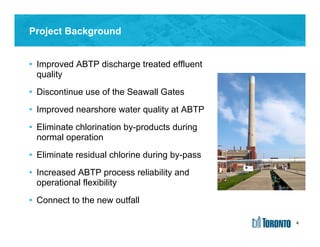

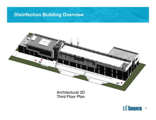
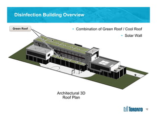
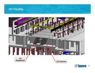
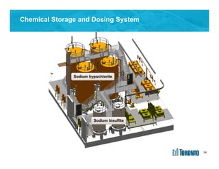
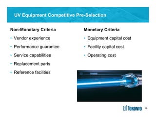
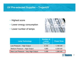
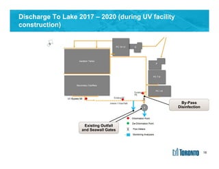
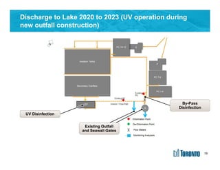
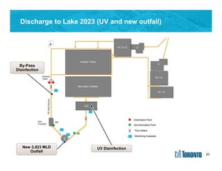
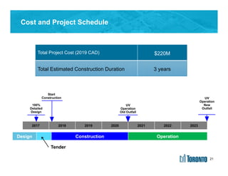
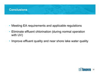


The document summarizes the detailed design of a UV disinfection system for the Ashbridges Bay Treatment Plant. The key points are: 1) The UV system will allow the plant to discontinue use of chlorine and seawall gates, improving effluent quality and lake water quality. 2) The design includes a new disinfection building to house UV equipment that was selected through a competitive process. 3) Construction will take place from 2017-2023, with the UV system operating during construction of a new outfall to replace the existing one.