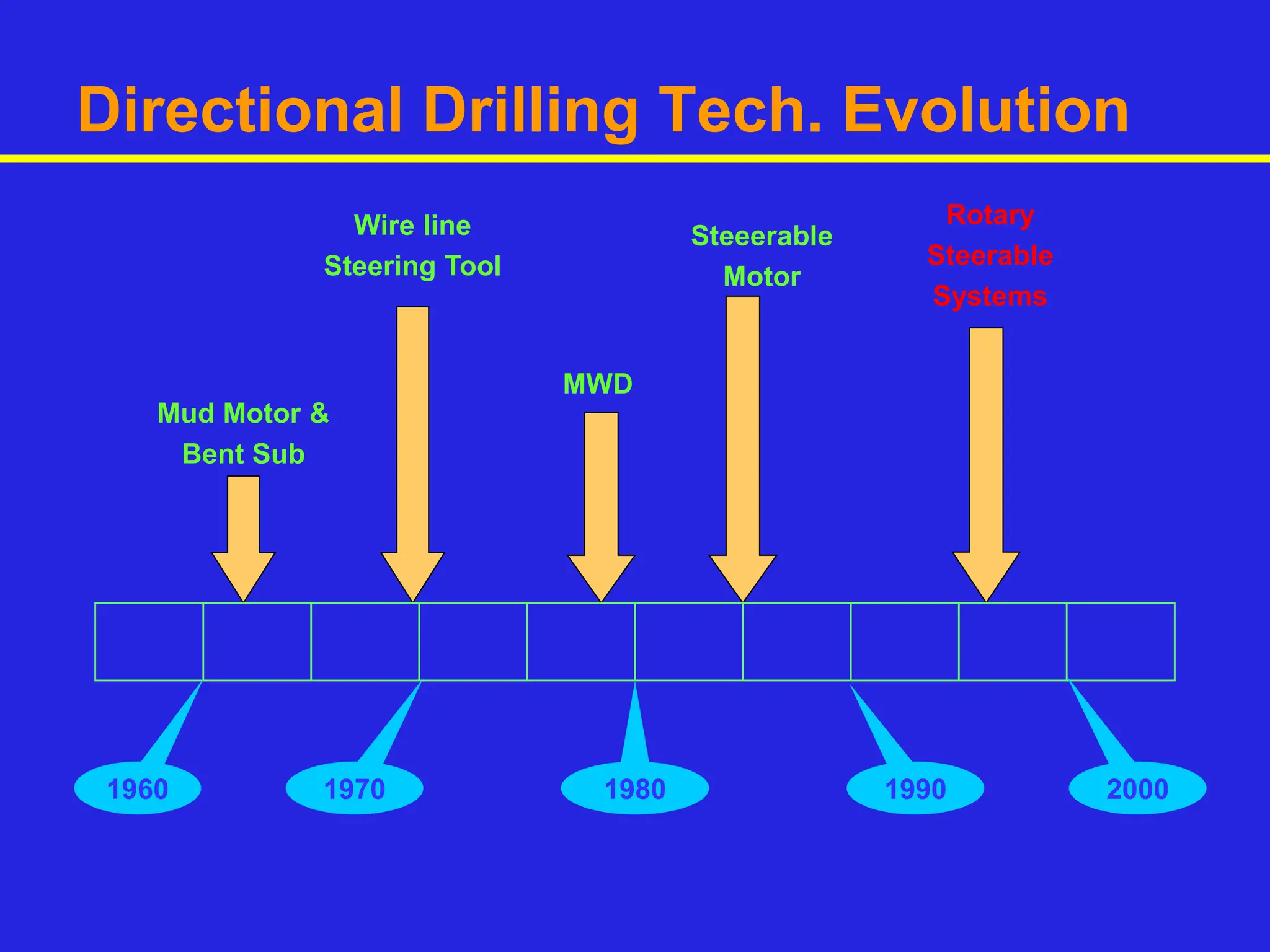
Booking open Available Pune Call Girls Pargaon 6297143586 Call Hot Indian Gi...
Directional drilling_Rotary steering system.ppt
1.
2. Directional Drilling Tech. Evolution
1960 1970 1980 1990 2000
Mud Motor &
Bent Sub
Wire line
Steering Tool
MWD
Steeerable
Motor
Rotary
Steerable
Systems
5. Cont.
The speed and torque
of a power section is
directly linked to the
number of lobes on
the rotor and stator.
The higher the
number of lobes, the
higher the torque and
the lower the RPM.
6. Dump Sub
Allows string to fill or
drain when tripping
Allows low volume
circulation in stuck bit
situations
Not always used
7. Stator & Rotor
Rotor is hard
Stator is flexible
Stator housing is thin
Elastomer lined - steel
tube stator
Chrome coated steel
rotor
Converts Hydraulic HP
(flow & pressure) to
Mechanical HP (rpm &
torque)
8.
9. Steerable Motors
Steerable motors, allow simultaneous
control of well bore azimuth and inclination.
A typical steerable motor assembly
consists of a power generating section,
through which drilling fluid is pumped to
turn the bit.
Drilling is accomplished in two modes-
rotating & sliding.
In slide mode- tendency to stuck.
In slide mode HP available to turn bit
reduces, which, combined with sliding
friction, decreases ROP.
In severe ERD wells, frictional forces during
sliding are so high,& due to insufficient
axial weight to overcome drag, further
drilling is not possible.
10. Steerable Motors
Changing Trajectory (Sliding)
• Drill-string Rotation Stopped
• Bit pointed in desired direction
• Interval drilled without drill-
string rotation
Straight Sections (Rotating)
• Drill-string rotated
continuously
• Stabilization may provide
inclination control
“Sliding” “Rotating”
11. Conventional Technology
Directional Drilling Motor + MWD behind
Requires oriented drilling to change drilling
direction
Reduced rate of penetration
Impaired cutting transportation
Poor hole cleaning
Directional changes are getting difficult in long
or complex wells
Often roller cone bits required to carry out
directional work.
12. Steerable Motor vs. RSS
Slide drilling introduces
undesirable inefficiencies.
Switching from the sliding
mode to the rotating mode
while drilling with
steerable tools can result
in a more tortuous path to
the target.
Despite these challenges,
directional drilling with
steerable motor remains
cost-effective and is still
the most widely used
method of directional
drilling.
14. Rotary Steerable Systems
Drivers for RSS Development
Elimination of Bent Tools
Borehole quality with possible string rotation
Automated down hole control over well path
With the invention of RSS directional drilling
efficiency further improved over steerable
systems.
Also improvement in placement accuracy
enabled to go for severe ERD & complex 3D
well profiles.
RSS probably most important technology to
drilling since Top drive.
15. Components
RSS includes
Steering Unit Few feet from bit
MWD Sensors
Down linking device to drilling assembly to
change course.
Advance system incorporates
Formation evaluation sensors
Drilling dynamics & Pressure sensor
18. Operating Principles
Push-the-bit: In this method RSS steers
by applying a side load to the bit, forcing
the bit’s outer cutting structure and gauge
to cut side-ways into the formation to drill
a curved hole in desired direction.
Short gauge bits are used in this
operation, it is possible to quickly change
hole direction. But this make hole spiral in
hold section, that is a disadvantage. Also
unconsolidated formations are not suitable
for pads used for push.
19. Operating Principles
Point-the-bit: In this method RSS steers
by pointing the bit in the desired direction
via flexing of tool inside the housing. The
drill bit face is pointed precisely in the
direction to be drilled without side load on
the bit.
Here longer gauge bits are used and well
bore spiraling is reduced, but it takes
longer interval to change direction with
this method.
21. How does RSS Work [Point the bit]
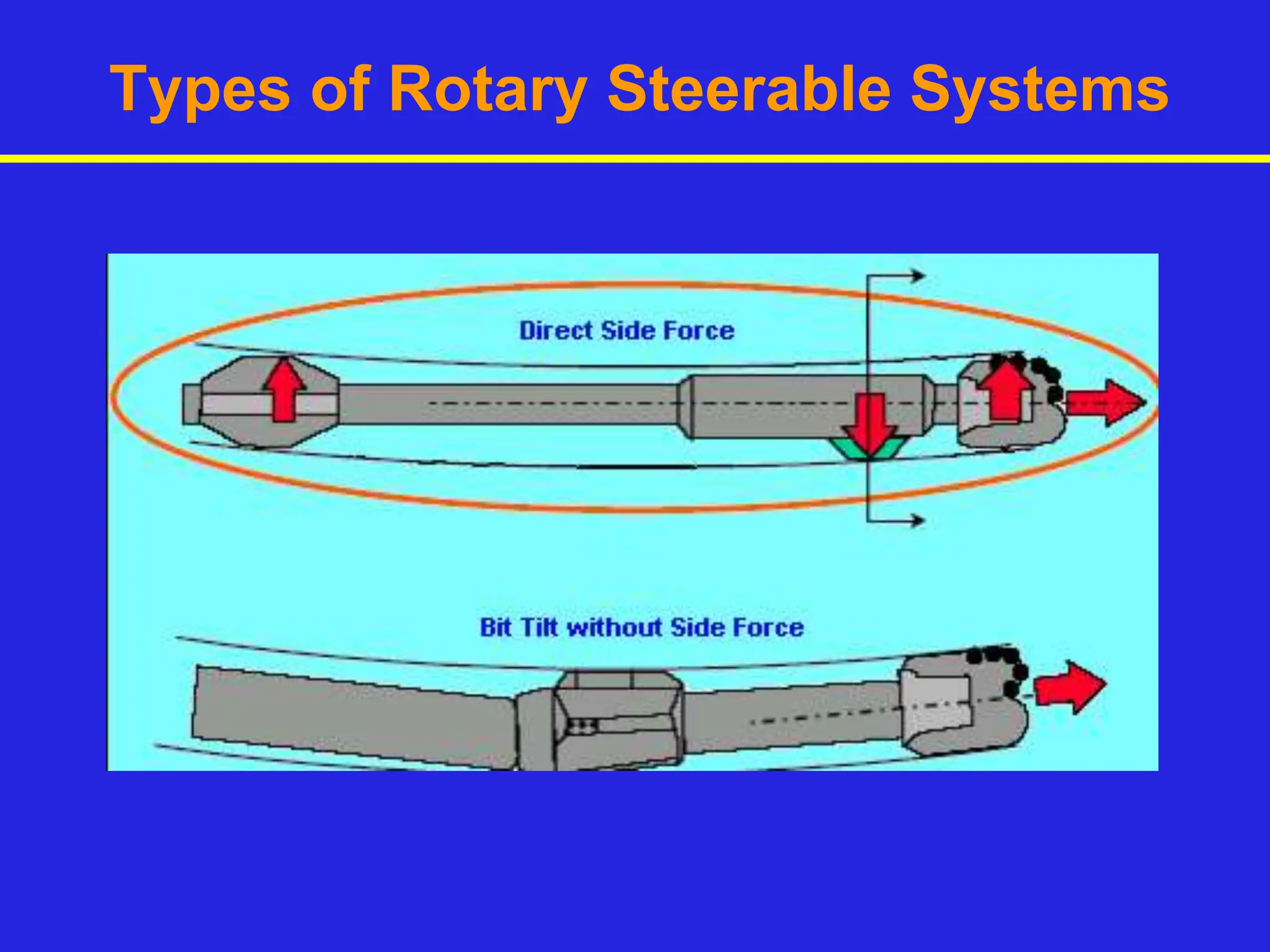
In this system bit direction is controlled by deflection of
the bit drive shaft rather than relying on bit side forces
to steer the well while rotating the drill string.
In a compact bais unit- a pair of eccentric rings, one
nested inside the other, deviate a drive shaft mounted
on bearings at each end and enclosed in a non-rotating
outer sleeve.
Control system is self correcting guidance system,
uses near bit inclination signals and accordingly self
correcting electronics automatically maintain
directional tool face and inclination.
An anti-rotation device prevents slippage of the outer
housing while the tool is in the deflected, steering
mode, allowing for a stable tool face orientation.
22. How does RSS Work [Point the bit]
Shaft deflection is achieved by a pair of eccentric
rings that can be rotated to any desired tool face
setting and varying degree of offset from the center.
For maximum operating life and reliability, the
system's bearings, seals, and other internal moving
components are all immersed in lubricating oil. And,
because the tool operates independently of well
bore fluids, there are virtually no mud compatibility
problems.
A pressure compensator maintains a slight positive
internal pressure across rotary seals.
Example: Geo-Pilot ® Rotary Steerable system
24. Rotary Steerable Technology + Motors
Advantages of RCLS and power and bit rotation speed of
motors can be combined to further optimize drilling in
special environments.
To achieve planned ROP in severe ERD & other
applications, sometimes higher RPM are required but
limitations are
Rig’s rotary system limitation
More wear on casing & drill pipe
Increase in downtime.
Modular motor’s pre-contoured stator can generate 50-
100% more torque than conventional elastomer-based
motors, and it reduces rotary speed without sacrificing
higher ROP. Motor is positioned immediately above the
steering unit and below MWD/LWD system. It is hard
wired to allow full communication of near bit inclination
etc.
Models: INTEQ’s Auto Trak X-treme & Schlumberger’s vorteX.