Dr. A.P.J. AbdulKalam U.I.T., Jhabua (M.P)
Department of Computer Science &
Engineering
Presented By:- Sagar Mishra.
Semester/ Year :- 3rd
SEM/ 2nd
.
Branch:- C.S.E .
Presented to :- Prof. Fareen Khan.
Topic: Logic Gate.
Session:2025-26
2.
Content:-
What is logicgates
Types of logic gate
(a) AND logic gate
(b) OR logic gate
(c) NOT logic gate
Application of logic gate
3.
What is logicgate:-
A logic gate is a basic building block of digital electronics. It is an
electronic circuit that performs a logical operation on one or
more binary inputs (0 or 1) and produces a single binary output.
4.
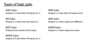
AND Gate:-
Output is1 only when all inputs are 1.
OR Gate:-
Output is 1 when any one input is 1.
NOT Gate:-
Produces the inverse of the input.
NAND Gate:-
Output is 0 only when all inputs are 1.
Types of logic gate:-
NOR Gate:
Output is 1 only when all inputs are 0.
XOR Gate:-
Output is 1 when inputs are different .
XNOR Gate:-
Output is 1 when inputs are same.
5.
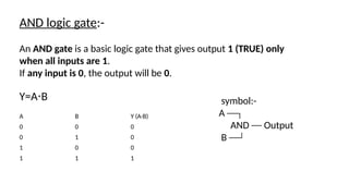
Y=A B
⋅
A BY (A·B)
0 0 0
0 1 0
1 0 0
1 1 1
AND logic gate:-
An AND gate is a basic logic gate that gives output 1 (TRUE) only
when all inputs are 1.
If any input is 0, the output will be 0.
symbol:-
A ──┐
AND ── Output
B ──┘
6.
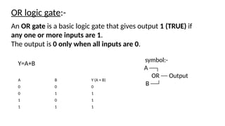
OR logic gate:-
Y=A+B
AnOR gate is a basic logic gate that gives output 1 (TRUE) if
any one or more inputs are 1.
The output is 0 only when all inputs are 0.
A B Y (A + B)
0 0 0
0 1 1
1 0 1
1 1 1
symbol:-
A ──┐
OR ── Output
B ──┘
7.
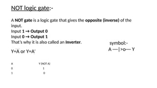
A NOT gateis a logic gate that gives the opposite (inverse) of the
input.
Input 1 → Output 0
Input 0 → Output 1
That’s why it is also called an Inverter.
NOT logic gate:-
A Y (NOT A)
0 1
1 0
Y=A or Y=A′
symbol:-
A ──|>o── Y


![DLD_-ASoat(41230301768)basic logic [1].pptx](https://cdn.slidesharecdn.com/ss_thumbnails/dld-asoat412303017681-251220103903-3c4281fc-thumbnail.jpg?width=640&height=640&fit=bounds)


![Water_pollution_pptx_20251220_190556_0000[1].pptx](https://cdn.slidesharecdn.com/ss_thumbnails/waterpollutionpptx2025122019055600001-260106150828-31b53774-thumbnail.jpg?width=640&height=640&fit=bounds)


