The document describes different types of power plants:
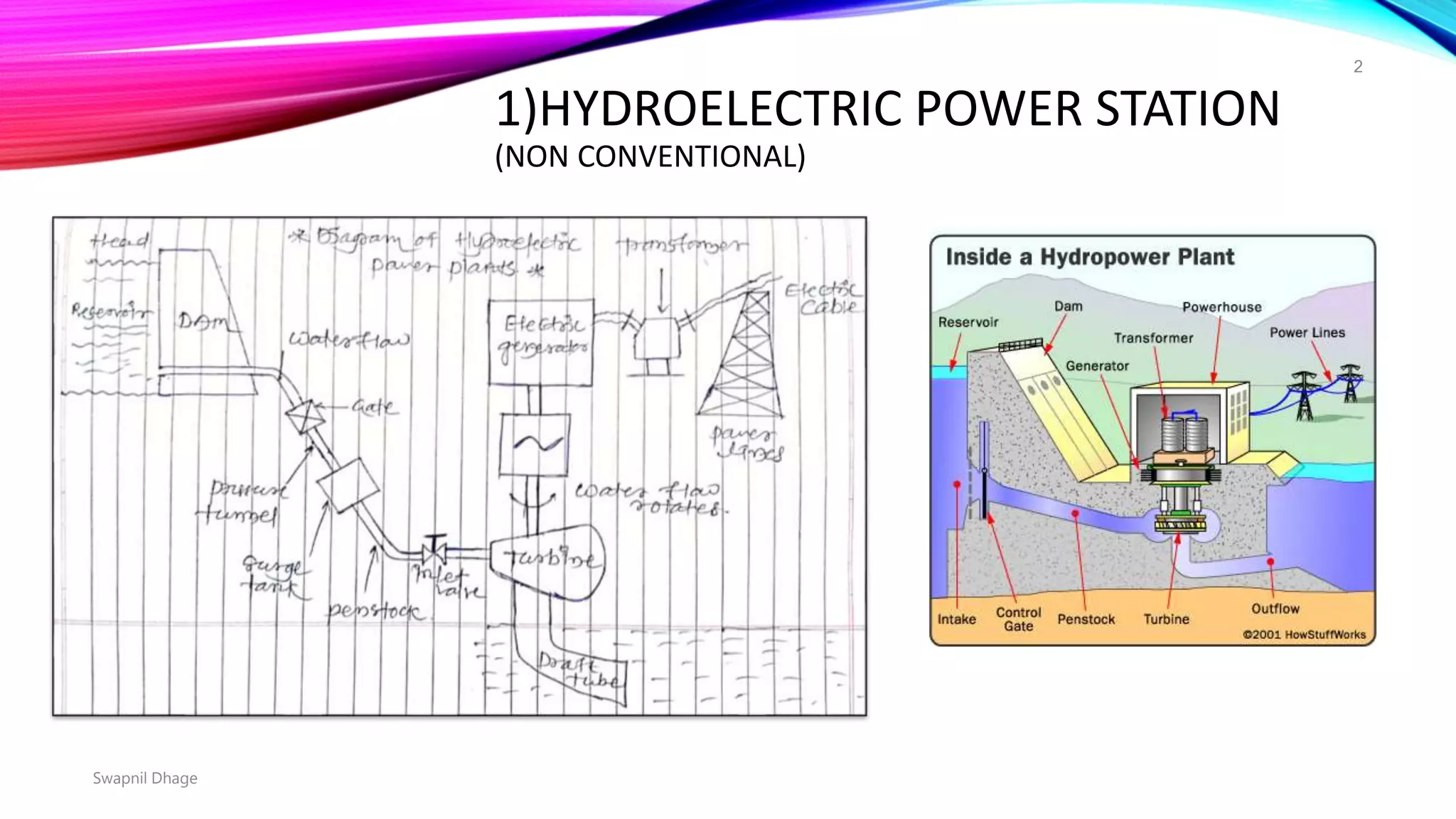
1) Hydroelectric plants use falling water to rotate turbines and generate electricity. Key components include dams, penstocks, turbines, generators, and transformers.
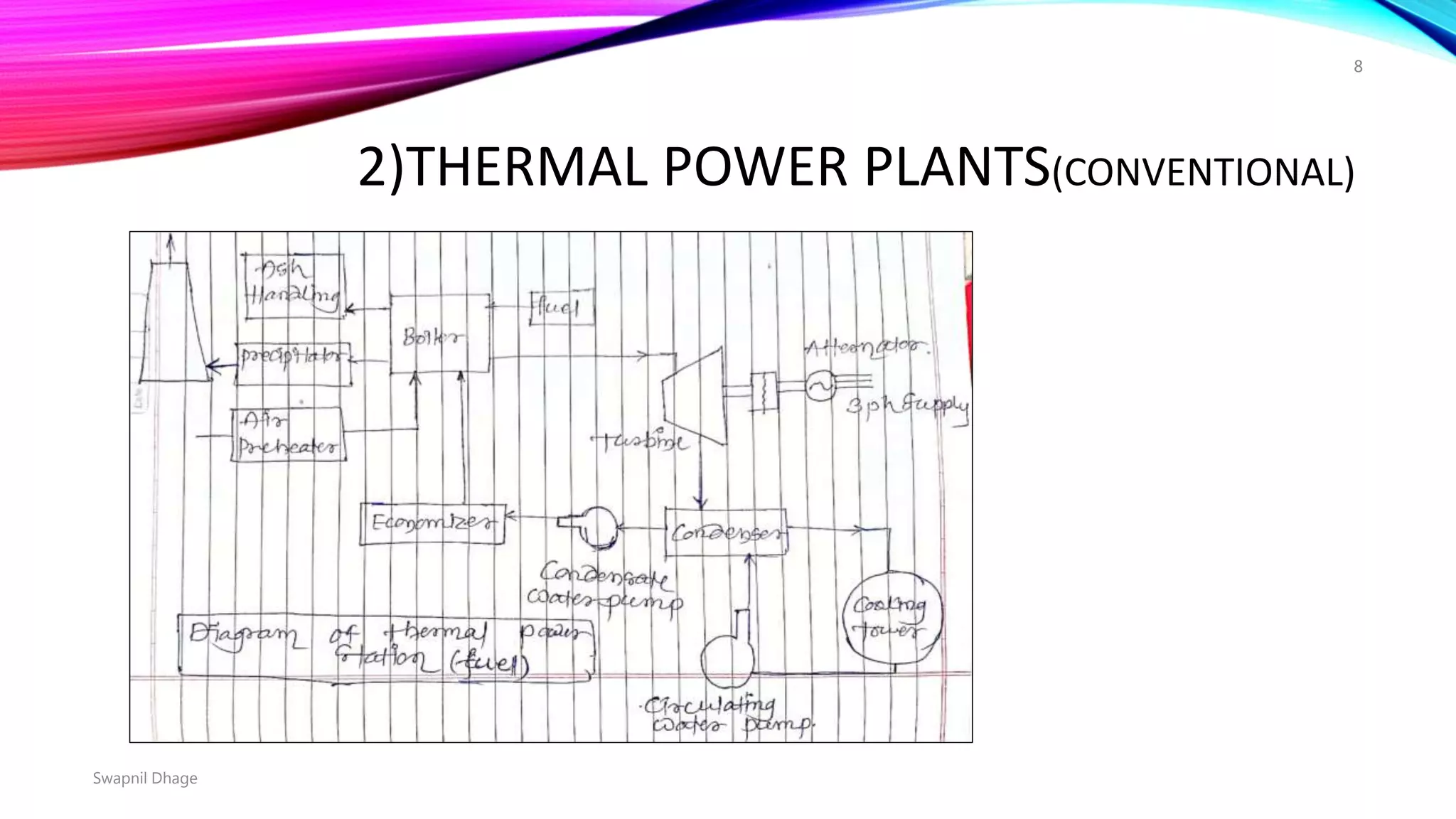
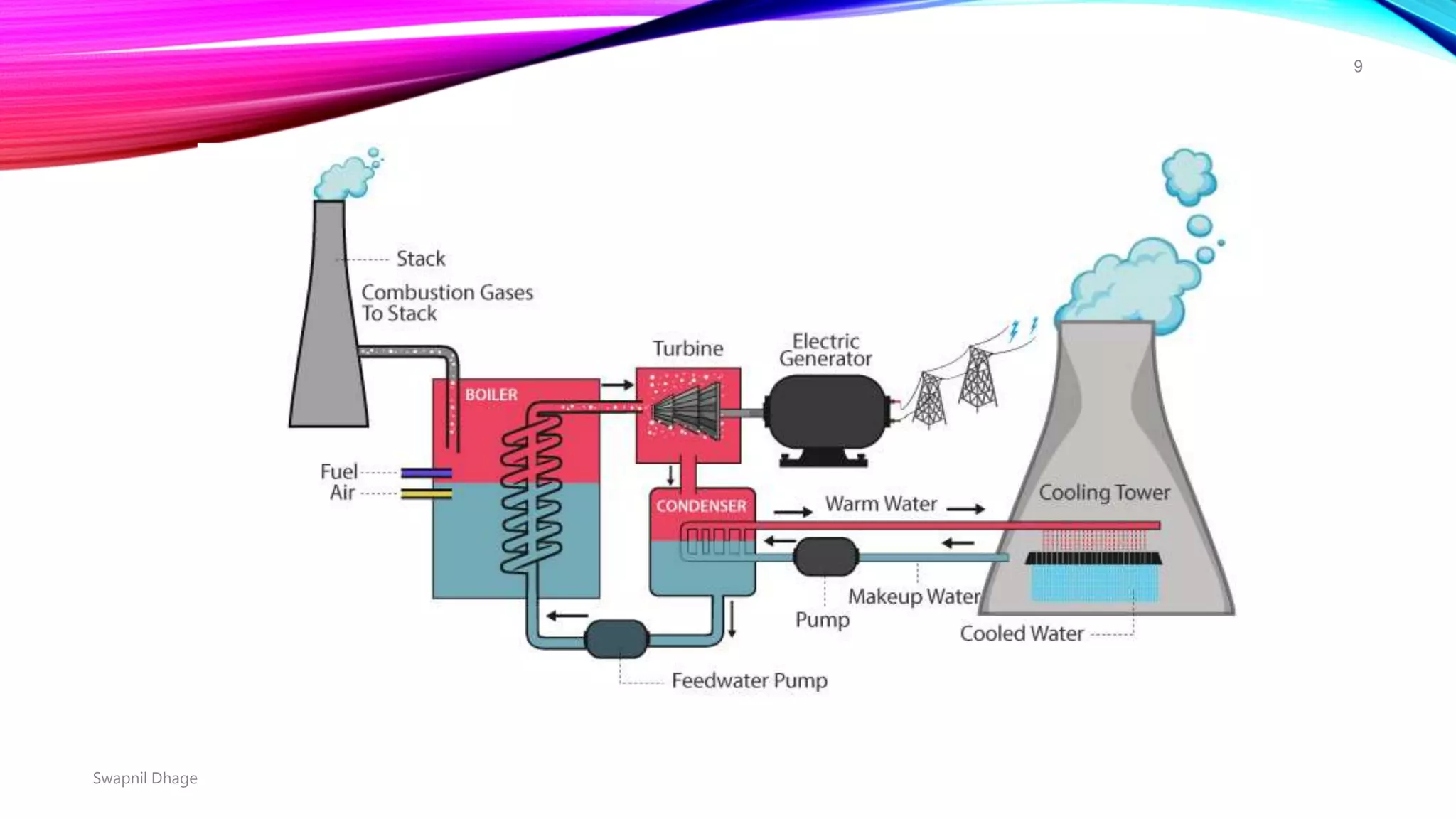
2) Thermal plants burn fuels to create high-pressure steam that drives turbines connected to generators. They include boilers, steam turbines, condensers, and feedwater pumps.
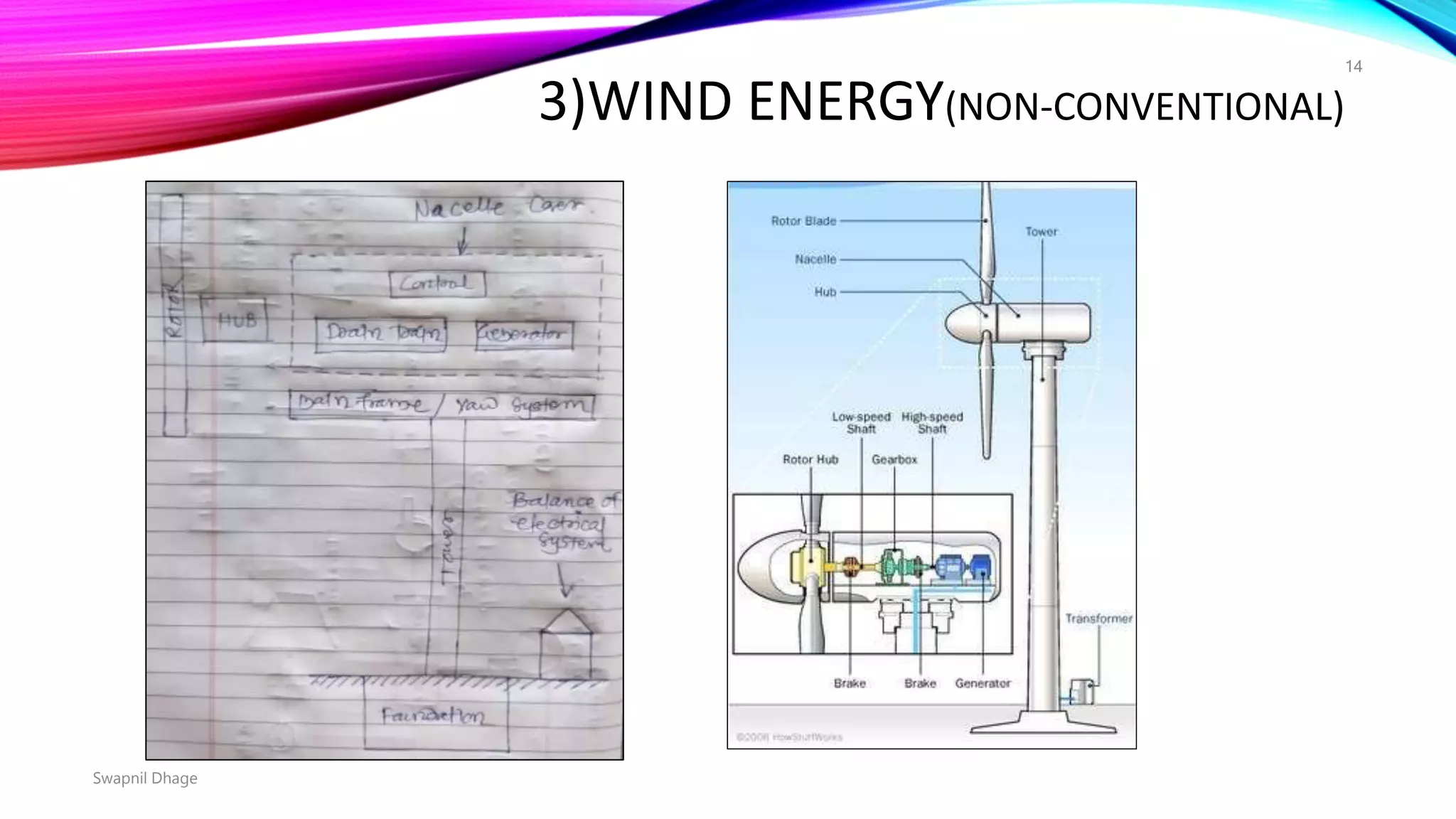
3) Wind turbines use rotor blades to convert wind's kinetic energy into mechanical energy that spins generators. Their components are rotors, drive trains, nacelles, towers, and machine controls.
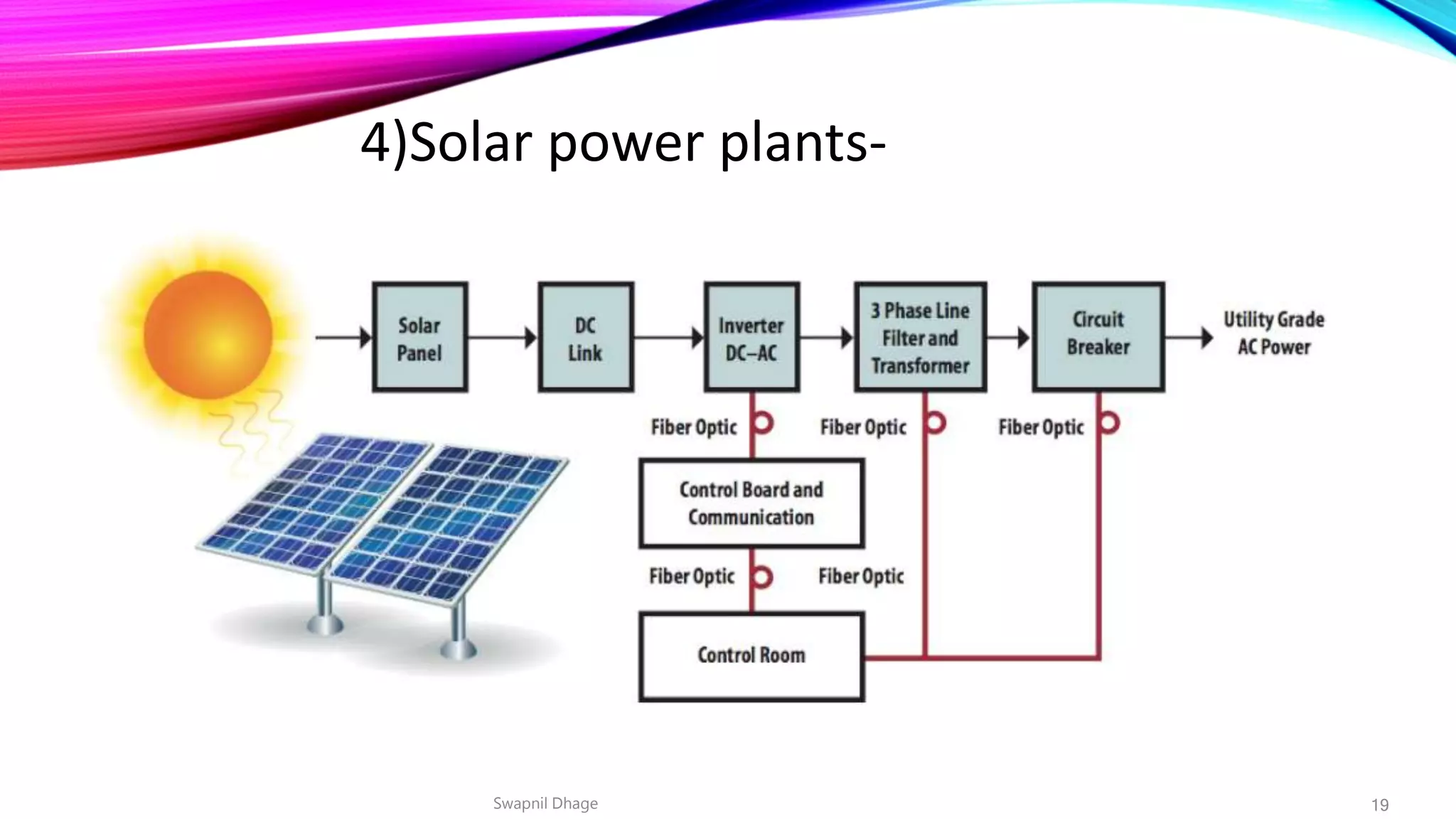
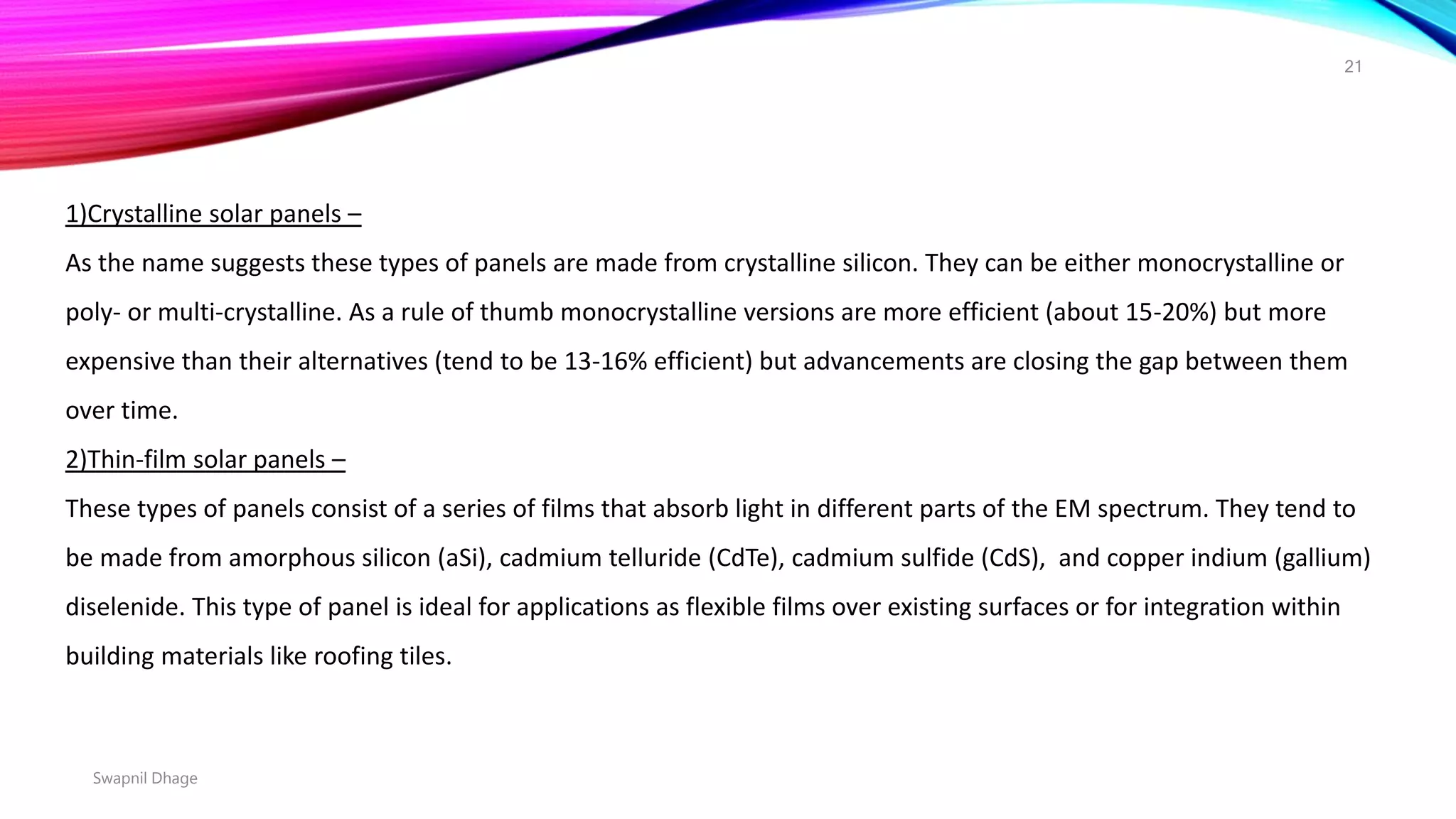
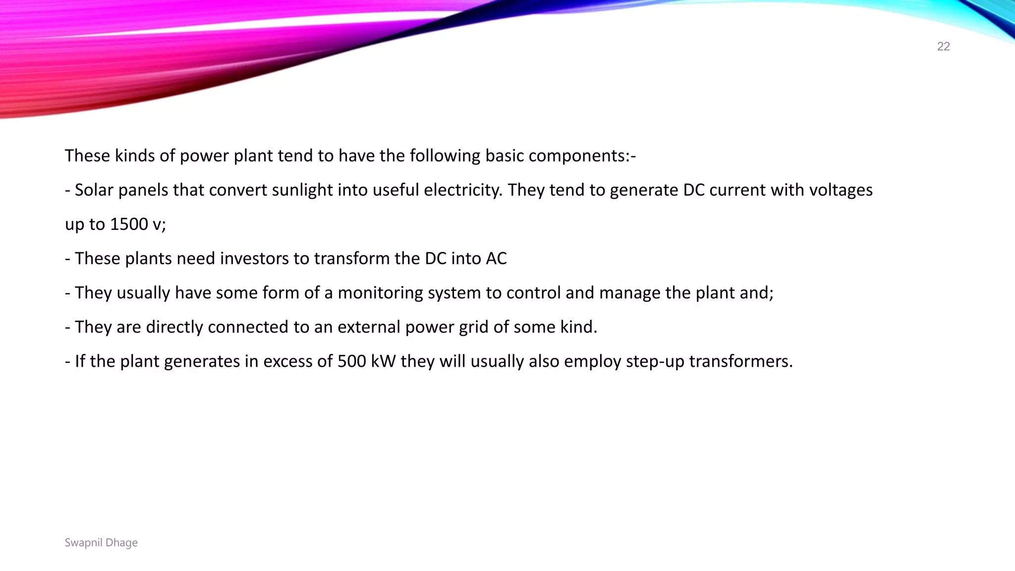
4) Solar plants use photovoltaic panels to convert sunlight into direct current, then inverters transform it into alternating
Unit I: Introduction to Protection System:
Introduction to protection system and its elements, functions of protective relaying, protective zones, primary and backup protection, desirable qualities of protective relaying, basic terminology.
Relays:
Electromagnetic, attracted and induction type relays, thermal relay, gas actuated relay, design considerations of electromagnetic relay.
Unit-II: Relay Application and Characteristics:
Amplitude and phase comparators, over current relays, directional relays, distance relays, differential relay.
Static Relays: Comparison with electromagnetic relay, classification and their description, over current relays, directional relay, distance relays, differential relay.
Unit-III Protection of Transmission Line:
Over current protection, distance protection, pilot wire protection, carrier current protection, protection of bus, auto re-closing,
Unit-IV: Circuit Breaking:
Properties of arc, arc extinction theories, re-striking voltage transient, current chopping, resistance switching, capacitive current interruption, short line interruption, circuit breaker ratings.
Testing Of Circuit Breaker: Classification, testing station and equipments, testing procedure, direct and indirect testing.
Unit-V Apparatus Protection:
Protection of Transformer, generator and motor.
Circuit Breaker: Operating modes, selection of circuit breakers, constructional features and operation of Bulk Oil, Minimum Oil, Air Blast, SF6, Vacuum and d. c. circuit breakers.
Solar power is the conversion of sunlight into electricity, through directly using photovoltaic (PV). Photovoltaic convert light into electric current using the photoelectric effect.
Operational description of 400kv switchyard NTPC Ramagundam RSTPSPradeep Avanigadda
400 KV Switchyard of Ramagundam Super Thermal Power Station is the most vital switching station in the southern Grid. 2600 MW of Bulk Power generated by three 200 MW Units and four 500 MW Units of NTPC Ramagundam is evacuated for supplying to the southern states.
Switchyard consists of four 400 KV busbars fed by 7 Nos. of generators, 10 Nos. of 400 KV feeders, 3 Nos of 220 KV feeders and two nos. of 132 Kv feeders as shown in the single line diagram of 400 Kv switch yard.
In addition to the above, four nos. of Tie Transformers, five nos. of Auto transformers, two nos. of Shunt Reactors and one Bus reactor are provided.
Electrical Technology was founded on the remarkable discovery by Faraday that a changing magnetic flux creates an electric field. Out of that discovery, grew the largest and most complex engineering achievement of man : the electric power system. Indeed, life without electricity is now unimaginable. Electric power systems form the basic infrastructure of a country. Even as we read this, electrical energy is being produced at rates in excess of hundreds of giga-watts (1 GW = 1,000,000,000 W). Giant rotors spinning at speeds up to 3000 rotations per minute bring us the energy stored in the potential energy of water, or in fossil fuels. Yet we notice electricity only when the lights go out!
While the basic features of the electrical power system have remained practically unchanged in the past century, but there are some significant milestones in the evolution of electrical power systems.
Automatic generation control (AGC) is a system for adjusting the power output of multiple generators at different power plants, in response to changes in the load. Since a power grid requires that generation and load closely balance moment by moment, frequent adjustments to the output of generators are necessary. The balance can be judged by measuring the system frequency; if it is increasing, more power is being generated than used, which causes all the machines in the system to accelerate. If the system frequency is decreasing, more load is on the system than the instantaneous generation can provide, which causes all generators to slow down.
Er.Amit Chaurasiya studies at Azad Technical Campus Lucknow.All slide make very clear and easily understood suitable for Electrical Engineering students. I hope you will easily understand.
Introduction
HVDC transmission lines have become commercially successful in India and many other nations after 1980. High Voltage Direct Current Transmission is an alternative to 3 phase 50 Hz AC transmission. Particular applications of HVDC transmission lines are as follows:
Long 2 terminal Bipolar High Power HVDC systems – They have following advantages
• Economy in capital cost.
• Better power control.
• Lower transmission losses.
• Energy conservation.
• Higher stability limit.
Back to back HVDC Coupling Stations between two independently controlled AC networks
• Technically superior.
• Better stability of AC networks at both ends.
• Excellent interconnection.
• Large scale blackouts in interconnected ac networks are prevented.
Long High power submarine cable
• No continuous charging currents.
Multi terminal HVDC interconnection system between 3 or more independently controlled ac networks
• Accurate and fast control of power exchange between 3 or more ac networks.
• No total blackouts.
• Higher stability limits.
• Lower losses.
• Energy conversation.
Protection and switch gear requirements
The protection and switch gear requirements of HVDC systems is quite different from that of AC systems. In HVDC systems, protection and control functions are integrated with the thyristor converter control. There are no HVDC circuit breakers. For normal operation and control and for protection from abnormal currents and voltages etc. thyristor control is employed. In the event of single pole to ground faults which are beyond the capability of thyristor control; the AC circuit breakers of the faulty pole are tripped after reducing the power flow and fault is isolated. All the present HVDC systems are without HVDC circuit breaker in the DC poles. Circuit breakers are provided on AC side of converter transformers.
However, the HVDC Switching Devices in form of Metallic Return Transfer Breaker are necessary in the earth return path in present 2 terminal HVDC systems for interrupting earth return currents during change over from earth return to pole return.
Artificial current interruption principle
The artificial current zero principle must be employed in HVDC switching devices for interrupting of DC arcs. The artificial current zeroes are produced in the LC oscillatory circuit in the loop of circuit breaker while opening the contacts. The arc is extinguished by the circuit breaker. The HVDC circuit Breaker Pole has ZnO arresters in parallel with the main CB for absorbing switching overvoltages. Even though the development of HVDC Circuit breakers have been technically successful, they are not commercially used due to their high cost.
Schematic of DC Switching System and Waveform of Idc with Artificial Current zeroes.
As the main breaker opens at t1, the DC arc is initiated between the contacts. Idc flows through the arc in the MB. As the Triggered Vacuum Gap sparks over, the parall
Emergency Power Supplies: Electrical Distribution Design, Installation and Co...Living Online
This manual will enable you to understand the level of failure-proofing that specific equipment may require, evaluate available options objectively, specify the best and most economical solution, and manage the installation, commissioning and maintenance of the distribution system.
FOR MORE INFORMATION: http://www.idc-online.com/content/emergency-power-supplies-electrical-distribution-design-installation-and-commissioning-24?id=39
INTRODUCTION TO DIFFERENT TYPES OF POWER PLANTS.PDFhublikarsn
STEAM POWER PLANTS:
A thermal power station is a power plant in which the prime mover is steam driven. Water is heated, turns into steam and spins a steam turbine which drives an electrical generator. After it passes through the turbine, the steam is condensed in a condenser and recycled to where it was heated; this is known as a Rankine cycle. The greatest variation in the design of thermal power stations is due to the different fuel sources. Some prefer to use the term energy center because such facilities convert forms of heat energy into electricity. Some thermal power plants also deliver heat energy for industrial purposes, for district heating, or for desalination of water as well as delivering electrical power. A large proportion of CO2 is produced by the worlds fossil fired thermal power plants; efforts to reduce these outputs are various and widespread.
Coal and Ash Circuit
Coal and Ash circuit in a thermal power plant layout mainly takes care of feeding the boiler with coal from the storage for combustion. The ash that is generated during combustion is collected at the back of the boiler and removed to the ash storage by scrap conveyors. The combustion in the Coal and Ash circuit is controlled by regulating the speed and the quality of coal entering the grate and the damper openings.
Air and Gas Circuit
Air from the atmosphere is directed into the furnace through the air preheated by the action of a forced draught fan or induced draught fan. The dust from the air is removed before it enters the combustion chamber of the thermal power plant layout. The exhaust gases from the combustion heat the air, which goes through a heat exchanger and is finally let off into the environment.
Feed Water and Steam Circuit
The steam produced in the boiler is supplied to the turbines to generate power. The steam that is expelled by the prime mover in the thermal power plant layout is then condensed in a condenser for re-use in the boiler. The condensed water is forced through a pump into the feed water heaters where it is heated using the steam from different points in the turbine. To make up for the lost steam and water while passing through the various components of the thermal power plant layout, feed water is supplied through external sources. Feed water is purified in a purifying plant to reduce the dissolve salts that could scale the boiler tubes.
Cooling Water Circuit
The quantity of cooling water required to cool the steam in a thermal power plant layout is significantly high and hence it is supplied from a natural water source like a lake or a river. After passing through screens that remove particles that can plug the condenser tubes in a thermal power plant layout, it is passed through the condenser where the steam is condensed. The water is finally discharged back into the water source after cooling. Cooling water circuit can also be a closed system where the cooled water is sent through cooling towers for re-use in the power plant. The cooli
Abhinav Kumar Mechanical Engineering Vocational Training NTPC Ltd UnchaharABHINAV KUMAR
This is the vocational training report needed to be submitted with the EDC HR Dept in order to acquire the certificate of completion. And additional copy is submitted with the Mechanical Department of my respective college.
Generation of Electrical Power - Power Plants and Transmission Systems.maneesh001
Basics of generation of electricity by thermal, hydro, nuclear and renewable sources are provided in this document.
Students of APJ Abdul Kalam Technological University (KTU) may find this helpful for their fouth module preparations.
Natural farming @ Dr. Siddhartha S. Jena.pptxsidjena70
A brief about organic farming/ Natural farming/ Zero budget natural farming/ Subash Palekar Natural farming which keeps us and environment safe and healthy. Next gen Agricultural practices of chemical free farming.
UNDERSTANDING WHAT GREEN WASHING IS!.pdfJulietMogola
Many companies today use green washing to lure the public into thinking they are conserving the environment but in real sense they are doing more harm. There have been such several cases from very big companies here in Kenya and also globally. This ranges from various sectors from manufacturing and goes to consumer products. Educating people on greenwashing will enable people to make better choices based on their analysis and not on what they see on marketing sites.
"Understanding the Carbon Cycle: Processes, Human Impacts, and Strategies for...MMariSelvam4
The carbon cycle is a critical component of Earth's environmental system, governing the movement and transformation of carbon through various reservoirs, including the atmosphere, oceans, soil, and living organisms. This complex cycle involves several key processes such as photosynthesis, respiration, decomposition, and carbon sequestration, each contributing to the regulation of carbon levels on the planet.
Human activities, particularly fossil fuel combustion and deforestation, have significantly altered the natural carbon cycle, leading to increased atmospheric carbon dioxide concentrations and driving climate change. Understanding the intricacies of the carbon cycle is essential for assessing the impacts of these changes and developing effective mitigation strategies.
By studying the carbon cycle, scientists can identify carbon sources and sinks, measure carbon fluxes, and predict future trends. This knowledge is crucial for crafting policies aimed at reducing carbon emissions, enhancing carbon storage, and promoting sustainable practices. The carbon cycle's interplay with climate systems, ecosystems, and human activities underscores its importance in maintaining a stable and healthy planet.
In-depth exploration of the carbon cycle reveals the delicate balance required to sustain life and the urgent need to address anthropogenic influences. Through research, education, and policy, we can work towards restoring equilibrium in the carbon cycle and ensuring a sustainable future for generations to come.
Artificial Reefs by Kuddle Life Foundation - May 2024punit537210
Situated in Pondicherry, India, Kuddle Life Foundation is a charitable, non-profit and non-governmental organization (NGO) dedicated to improving the living standards of coastal communities and simultaneously placing a strong emphasis on the protection of marine ecosystems.
One of the key areas we work in is Artificial Reefs. This presentation captures our journey so far and our learnings. We hope you get as excited about marine conservation and artificial reefs as we are.
Please visit our website: https://kuddlelife.org
Our Instagram channel:
@kuddlelifefoundation
Our Linkedin Page:
https://www.linkedin.com/company/kuddlelifefoundation/
and write to us if you have any questions:
info@kuddlelife.org
Characterization and the Kinetics of drying at the drying oven and with micro...Open Access Research Paper
The objective of this work is to contribute to valorization de Nephelium lappaceum by the characterization of kinetics of drying of seeds of Nephelium lappaceum. The seeds were dehydrated until a constant mass respectively in a drying oven and a microwawe oven. The temperatures and the powers of drying are respectively: 50, 60 and 70°C and 140, 280 and 420 W. The results show that the curves of drying of seeds of Nephelium lappaceum do not present a phase of constant kinetics. The coefficients of diffusion vary between 2.09.10-8 to 2.98. 10-8m-2/s in the interval of 50°C at 70°C and between 4.83×10-07 at 9.04×10-07 m-8/s for the powers going of 140 W with 420 W the relation between Arrhenius and a value of energy of activation of 16.49 kJ. mol-1 expressed the effect of the temperature on effective diffusivity.
Willie Nelson Net Worth: A Journey Through Music, Movies, and Business Venturesgreendigital
Willie Nelson is a name that resonates within the world of music and entertainment. Known for his unique voice, and masterful guitar skills. and an extraordinary career spanning several decades. Nelson has become a legend in the country music scene. But, his influence extends far beyond the realm of music. with ventures in acting, writing, activism, and business. This comprehensive article delves into Willie Nelson net worth. exploring the various facets of his career that have contributed to his large fortune.
Follow us on: Pinterest
Introduction
Willie Nelson net worth is a testament to his enduring influence and success in many fields. Born on April 29, 1933, in Abbott, Texas. Nelson's journey from a humble beginning to becoming one of the most iconic figures in American music is nothing short of inspirational. His net worth, which estimated to be around $25 million as of 2024. reflects a career that is as diverse as it is prolific.
Early Life and Musical Beginnings
Humble Origins
Willie Hugh Nelson was born during the Great Depression. a time of significant economic hardship in the United States. Raised by his grandparents. Nelson found solace and inspiration in music from an early age. His grandmother taught him to play the guitar. setting the stage for what would become an illustrious career.
First Steps in Music
Nelson's initial foray into the music industry was fraught with challenges. He moved to Nashville, Tennessee, to pursue his dreams, but success did not come . Working as a songwriter, Nelson penned hits for other artists. which helped him gain a foothold in the competitive music scene. His songwriting skills contributed to his early earnings. laying the foundation for his net worth.
Rise to Stardom
Breakthrough Albums
The 1970s marked a turning point in Willie Nelson's career. His albums "Shotgun Willie" (1973), "Red Headed Stranger" (1975). and "Stardust" (1978) received critical acclaim and commercial success. These albums not only solidified his position in the country music genre. but also introduced his music to a broader audience. The success of these albums played a crucial role in boosting Willie Nelson net worth.
Iconic Songs
Willie Nelson net worth is also attributed to his extensive catalog of hit songs. Tracks like "Blue Eyes Crying in the Rain," "On the Road Again," and "Always on My Mind" have become timeless classics. These songs have not only earned Nelson large royalties but have also ensured his continued relevance in the music industry.
Acting and Film Career
Hollywood Ventures
In addition to his music career, Willie Nelson has also made a mark in Hollywood. His distinctive personality and on-screen presence have landed him roles in several films and television shows. Notable appearances include roles in "The Electric Horseman" (1979), "Honeysuckle Rose" (1980), and "Barbarosa" (1982). These acting gigs have added a significant amount to Willie Nelson net worth.
Television Appearances
Nelson's char
Alert-driven Community-based Forest monitoring: A case of the Peruvian Amazon
Different power generatrion diagram and its breif explain by swapnil d
1. Q.2 DRAW THE DETAIL DIAGRAM OF POWER
GENERATION BY VARIOUS TYPES OF POWER PLANTS
AND EXPLAIN IN BRIEF.
PRESENTED BY- SWAPNIL P DHAGE
Swapnil Dhage
1
3. A power plants that produce the electricity by using water to rotate the
turbine which drives generator, is called as the hydroelectric power plants.
Electricity is produce by the energy of falling water is called as the
hydroelectricity.
Different Parts are used in this power plants-
1) Dam and Reservoir
2) Control Gate
3) Penstock:
4) Water Turbine
5) Generator
6) Surge Tank:-
7) Transformer-
Swapnil Dhage
3
4. 1.Dam and Reservoir:
The dam is constructed on a large river in hilly areas to ensure sufficient water storage at height.
The dam forms a large reservoir behind it.
The height of water level (called as water head) in the reservoir determines how much of potential energy
is stored in it.
2.Control Gate:
Water from the reservoir is allowed to flow through the penstock to the turbine.
The amount of water which is to be released in the penstock can be controlled by a control gate.
When the control gate is fully opened, maximum amount of water is released through the penstock.
3.Penstock:
A penstock is a huge steel pipe which carries water from the reservoir to the turbine.
Potential energy of the water is converted into kinetic energy as it flows down through the penstock due
to gravity.
Swapnil Dhage
4
5. 4.Water Turbine:
Water from the penstock is taken into the water turbine.
The turbine is mechanically coupled to an electric generator. Kinetic energy of the water drives the
turbine and consequently the generator gets driven.
There are two main types of water turbine-
(i) Impulse turbine and (ii) Reaction turbine.
Impulse turbines are used for large heads and reaction turbines are used for low and medium heads.
5.Generator:-
A generator is mounted in the power house and it is mechanically coupled to the turbine shaft.
When the turbine blades are rotated, it drives the generator and electricity is generated which is then
stepped up with the help of a transformer for the transmission purpose.
Swapnil Dhage
5
6. 6.Surge Tank:
Surge tanks are usually provided in high or medium head power plants when considerably long
penstock is required.
A surge tank is a small reservoir or tank which is open at the top.
It is fitted between the reservoir and the power house.
The water level in the surge tank rises or falls to reduce the pressure swings in the penstock.
When there is sudden reduction in load on the turbine, the governor closes the gates of the turbine to
reduce the water flow.
This causes pressure to increase abnormally in the penstock. This is prevented by using a surge
tank, in which the water level rises to reduce the pressure.
On the other hand, the surge tank provides excess water needed when the gates are suddenly
opened to meet the increased load demand.
Swapnil Dhage
6
7. 7.Transformer-
The electricity generated inside the generator is not of sufficient voltage.
The transformer converts the alternating current produced from within the generator
to the high voltage current.
The transformer comprises of two coils:
1) the supply coil and
2) the outlet coil.
Current is supplied to the supply coil, from where it passes to the outlet coil.
The number of turns in the outlet coil decides the voltage of output electricity from the
transformer.
If the numbers of turns in outlet coil are double of supply coil, the voltage produced is
also double.
Swapnil Dhage
7
10. Basic Principle-
The burning of fuels such as oil, coal and LNG (liquefied natural gas) fires a boiler to generate high-
temperature, high-pressure steam.
This steam is used to drive a steam turbine. A generator attached to the steam turbine generates electricity.
Parts used in this plants-
1) Boiler
2) Economizer
3) Air Pre-heater:
4) Steam Turbine
5) Condenser
6) Alternator
7) Feed Water Pump
Swapnil Dhage
10
11. 1.Boiler:
The mixture of pulverized coal and air (usually preheated air) is taken into boiler and then burnt in the
combustion zone.
On ignition of fuel a large fireball is formed at the center of the boiler and large amount of heat energy
is radiated from it.
the heat energy is utilized to convert the water into steam at high temperature and pressure.
Steel tubes run along the boiler walls in which water is converted in steam.
The flue gases from the boiler make their way through superheater, economizer, air preheater and
finally get exhausted to the atmosphere from the chimney.
2.Economizer:
An economizer is essentially a feed water heater which heats the water before supplying to the boiler.
Swapnil Dhage
11
12. 3.Air pre-heater:-
The primary air fan takes air from the atmosphere and it is then warmed in the air pre-heater.
Pre-heated air is injected with coal in the boiler.
The advantage of pre-heating the air is that it improves the coal combustion.
4.Steam turbine:-
High pressure super heated steam is fed to the steam turbine which causes turbine blades to rotate.
Energy in the steam is converted into mechanical energy in the steam turbine which acts as the prime mover.
The pressure and temperature of the steam falls to a lower value and it expands in volume as it passes through
the turbine.
The expanded low pressure steam is exhausted in the condenser.
5.Condenser:
The exhausted steam is condensed in the condenser by means of cold water circulation.
Here, the steam loses it's pressure as well as temperature and it is converted back into water.
Condensing is essential because, compressing a fluid which is in gaseous state requires a huge amount of
energy with respect to the energy required in compressing liquid.
Thus, condensing increases efficiency of the cycle
Swapnil Dhage
12
13. 6.Alternator-
The steam turbine is coupled to an alternator.
When the turbine rotates the alternator, electrical energy is generated.
This generated electrical voltage is then stepped up with the help of a transformer and then
transmitted where it is to be utilized.
7.Feed water pump:
The condensed water is again fed to the boiler by a feed water pump. Some water may be lost
during the cycle, which is suitably supplied from an external water source.
Swapnil Dhage
13
15. -A wind turbine is a device that converts kinetic energy from the wind into electricity.
The blades of a wind turbine turn between 13 and 20 revolutions per minute, depending on their technology, at
a constant or variable velocity, where the velocity of the rotor varies in relation to the velocity of the wind in
order to reach a greater efficiency.
Part of wind power-
1) The rotor, consisting of the blades and the supporting hub.
2) The drive train, which includes the rotating parts of the wind turbine (exclusive of the rotor) it usually consists of shafts,
gearbox, coupling, a mechanical brake, and the generator.
3) The nacelle and main frame, including wind turbine housing, bedplate, and the yaw system.
4) The tower and the foundation.
5) The machine controls.
6) The balance of the electrical system, including cables, switchgear, transformers, and
possibly electronic power converters.
Swapnil Dhage
15
16. 1.Rotor:-
-It is the rotating part of the wind turbine. It transfers the energy in the wind to the shaft.
The rotor hub holds the wind turbine blades while connected to the gearbox via the low-speed shaft.
2.Drive train:-
-The drivetrain of a wind turbine is composed of the gearbox and the generator, the necessary components that a turbine needs to
produce electricity.
The gearbox is responsible for connecting the low-speed shaft attached to the turbine blades to the high-speed shaft attached to the
generator.
3.Generator-
The wind turbine generator converts mechanical energy to electrical energy.
On large wind turbines (above 100-150 kW) the voltage (tension) generated by the turbine is usually 690 V three-phase alternating
current (AC).
Swapnil Dhage
16
17. 4.Nacelle-
-It is the part of the turbine that houses the components that transform the wind's kinetic energy into mechanical
energy to turn a generator that produces electricity.
Most nacelles have common components, such as a hub, rotor, gearbox, generator, inverters, hydraulics, and bearings.
5.Tower-
-The tower of the wind turbine carries the nacelle and the rotor.
Towers for large wind turbines may be either tubular steel towers, lattice towers, or concrete towers. Guyed tubular
towers are only used for small wind turbines (battery chargers etc.)
6.Controls-
The control system for a wind turbine is important with respect to both machine operation and
power production.
A wind turbine control system includes the following components:
a) sensors – speed, position, flow, temperature, current, voltage, etc.;
Swapnil Dhage
17
18. Swapnil Dhage
18
b) controllers – mechanical mechanisms, electrical circuits;
c) power amplifiers – switches, electrical amplifiers, hydraulic
d) pumps, and valves;
e) actuators – motors, pistons, magnets, and solenoids;
f) intelligence – computers, microprocessors
20. Swapnil Dhage
20
The main part of a solar electric system is the solar panel.
There are various types of solar panel available in the market. Solar panels are also known as photovoltaic solar
panels.
Solar Photovoltaic (or PV) is a technology that converts sunlight into direct current electricity by using
semiconductors.
In contrast, Solar Thermal is a technology that utilizes the heat energy from the sun for heating or electricity
production.
The panels themselves come in various forms:-
1. Crystalline solar panels-
2. Thin-film solar panels-
21. Swapnil Dhage
21
1)Crystalline solar panels –
As the name suggests these types of panels are made from crystalline silicon. They can be either monocrystalline or
poly- or multi-crystalline. As a rule of thumb monocrystalline versions are more efficient (about 15-20%) but more
expensive than their alternatives (tend to be 13-16% efficient) but advancements are closing the gap between them
over time.
2)Thin-film solar panels –
These types of panels consist of a series of films that absorb light in different parts of the EM spectrum. They tend to
be made from amorphous silicon (aSi), cadmium telluride (CdTe), cadmium sulfide (CdS), and copper indium (gallium)
diselenide. This type of panel is ideal for applications as flexible films over existing surfaces or for integration within
building materials like roofing tiles.
22. Swapnil Dhage
22
These kinds of power plant tend to have the following basic components:-
- Solar panels that convert sunlight into useful electricity. They tend to generate DC current with voltages
up to 1500 v;
- These plants need investors to transform the DC into AC
- They usually have some form of a monitoring system to control and manage the plant and;
- They are directly connected to an external power grid of some kind.
- If the plant generates in excess of 500 kW they will usually also employ step-up transformers.