
![ANCHORAGE
Nature & degree of resistance to displacement
offered by an anatomic unit when used for the
purpose of effecting tooth movement. [Graber]
Resistance to unwanted tooth movement.
[Profitt]](https://image.slidesharecdn.com/differentanchoragesystemsinorthodontics-160506094138/75/Different-anchorage-systems-in-orthodontics-3-2048.jpg)


![REINFORCED ANCHORAGE
[MULTIPLE
ANCHORAGE]
Adding additional teeth
Anchorage from extraoral sources
Use of palate through bite plane/guide plane](https://image.slidesharecdn.com/differentanchoragesystemsinorthodontics-160506094138/75/Different-anchorage-systems-in-orthodontics-12-2048.jpg)
![INTRAMAXILLARY ANCHORAGE
•Resistance units are all situated within the
same jaw
INTERMAXILLARY ANCHORAGE
[BAKERS ANCHORAGE]
•Anchorage units situated in one jaw are used to
effect tooth movement in other jaw](https://image.slidesharecdn.com/differentanchoragesystemsinorthodontics-160506094138/75/Different-anchorage-systems-in-orthodontics-14-2048.jpg)


![LIGHT ARCH WIRE
TECHNIQUE
[BEGG
MECHANOTHERAPY]](https://image.slidesharecdn.com/differentanchoragesystemsinorthodontics-160506094138/75/Different-anchorage-systems-in-orthodontics-35-2048.jpg)


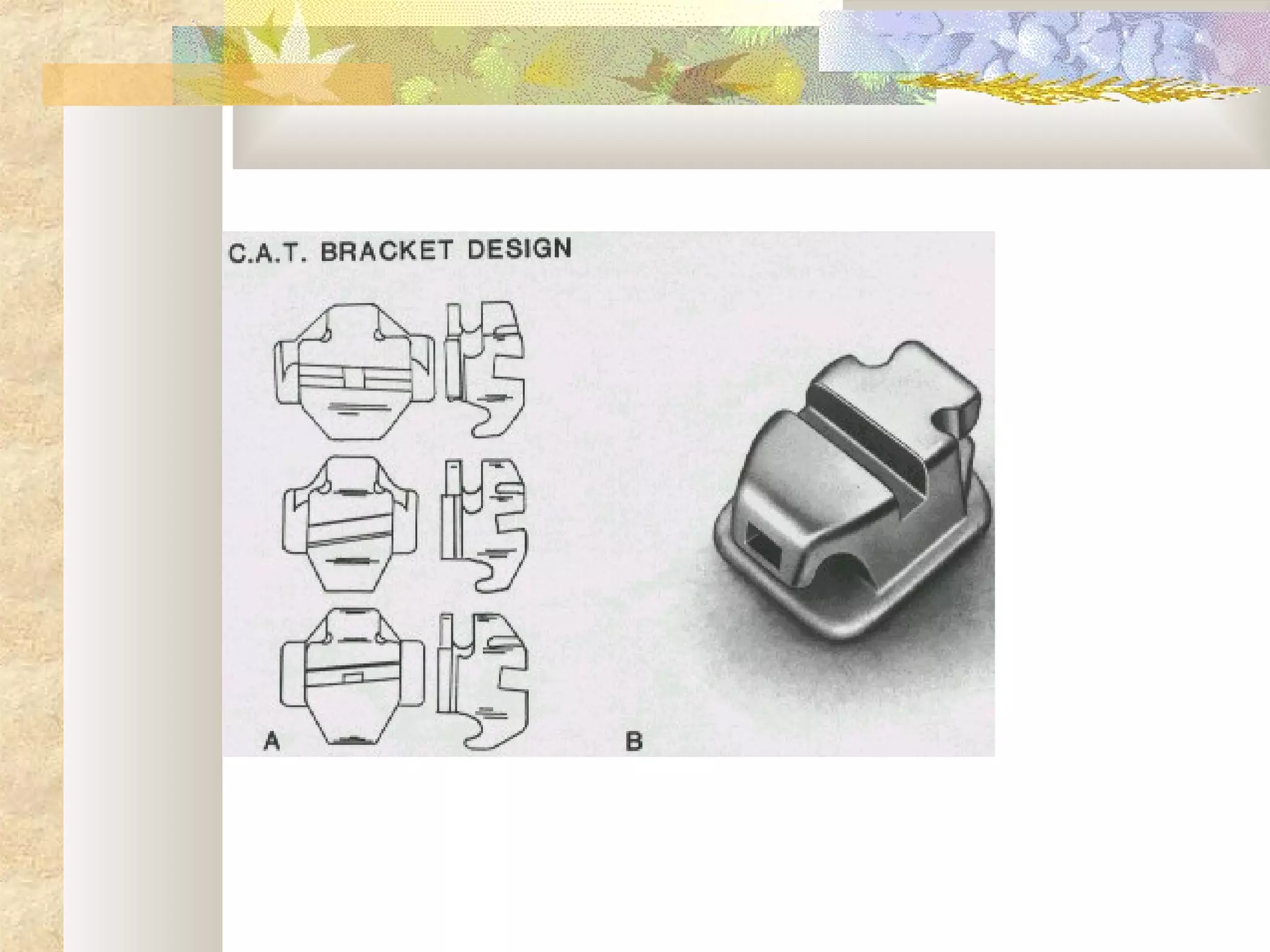


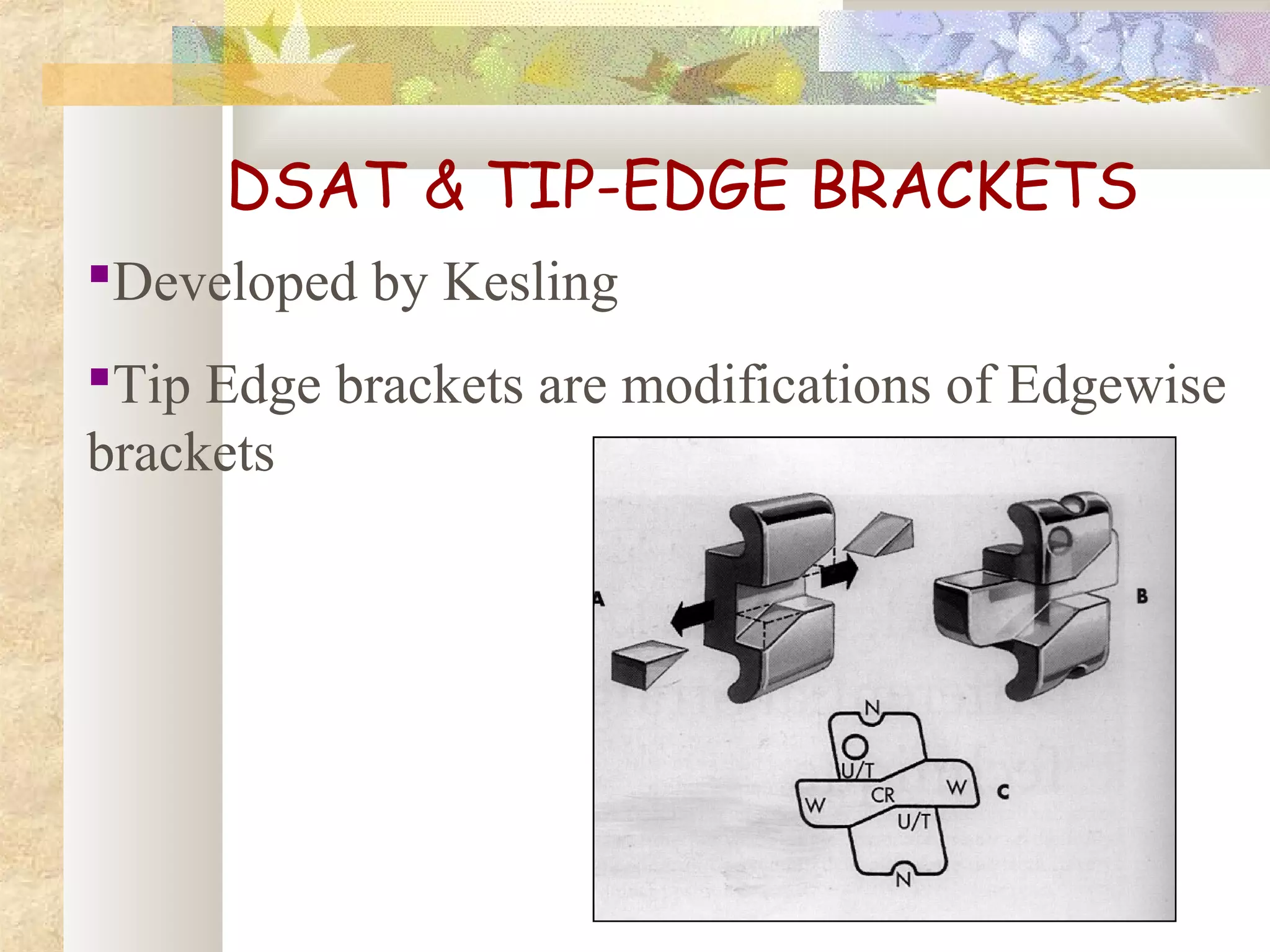
![DIFFERENTIA
L STRAIGHT
ARCH
TECHNIQUE
[TIP EDGE BRACKETS]](https://image.slidesharecdn.com/differentanchoragesystemsinorthodontics-160506094138/75/Different-anchorage-systems-in-orthodontics-55-2048.jpg)


![BRAKING MECHANICS
Side winder springs on PM, canines &
incisors
0.022’’ss or 0.0215x0.028’’ archwire
Heavy forces [6-8 oz] are used for molar
protraction](https://image.slidesharecdn.com/differentanchoragesystemsinorthodontics-160506094138/75/Different-anchorage-systems-in-orthodontics-63-2048.jpg)

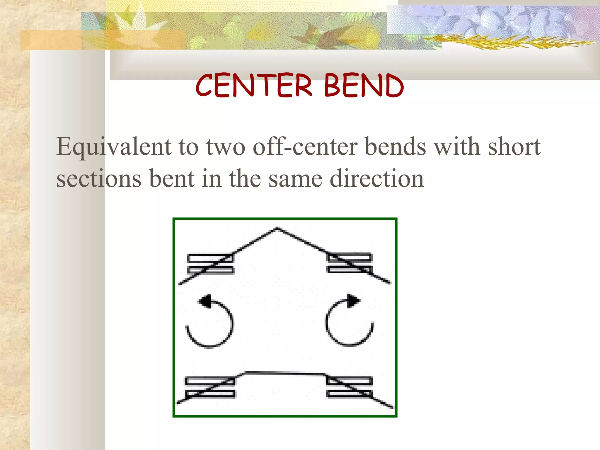
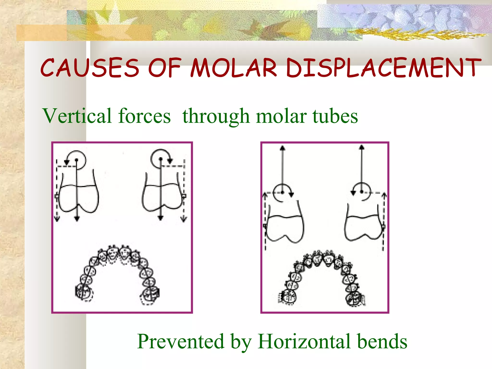
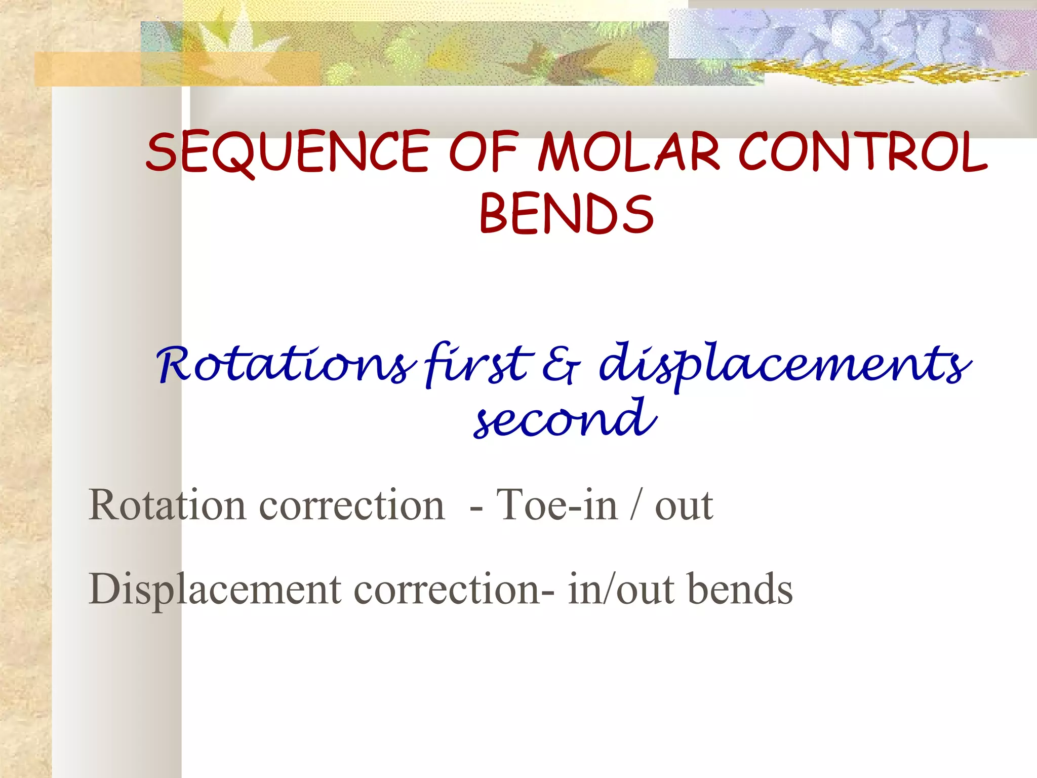
![MOLAR CONTROL
[MULLIGAN]](https://image.slidesharecdn.com/differentanchoragesystemsinorthodontics-160506094138/75/Different-anchorage-systems-in-orthodontics-65-2048.jpg)


![THIRD DEGREE [TOTAL] ANCHORGE
PREPARATION
Total discrepancy 14 to 20 mm, ANB
doesn’t exceed 5°
All the posterior teeth from II Pm to the
terminal molar be tipped distally to anchorage
preparation positions
Distal marginal ridges of the terminal molars
are below gum level](https://image.slidesharecdn.com/differentanchoragesystemsinorthodontics-160506094138/75/Different-anchorage-systems-in-orthodontics-80-2048.jpg)
![SEQUENTIAL MANDIBULAR
ANCHORAGE PEREPARATION
First described by Tweed
Cl III elastics & compensation bends
All the bends at the same time
Modified by Merrifield
Tipping only 2 teeth at a time
High pull head gear [ not cl III elastics]
Merrifield ‘10 – 2’ system](https://image.slidesharecdn.com/differentanchoragesystemsinorthodontics-160506094138/75/Different-anchorage-systems-in-orthodontics-81-2048.jpg)


![DIRECTION OF PULL & INDICATION
Low angle/normally growing patients – Cervical
[SN –MP < 37°] pull
SN – MP - 37 to 41° - Combination pull
SN – MP > 42° - High pull](https://image.slidesharecdn.com/differentanchoragesystemsinorthodontics-160506094138/75/Different-anchorage-systems-in-orthodontics-98-2048.jpg)


![SKELETAL ANCHORAGE
The conventional methods of reinforcing
anchorage are less than ideal, because they
either rely on structures that are themselves
potentially mobile [teeth] or they rely too
heavily on patient compliance [ HG & Elastics].
Skeletal anchorage overcomes many of these
shortcomings.](https://image.slidesharecdn.com/differentanchoragesystemsinorthodontics-160506094138/75/Different-anchorage-systems-in-orthodontics-152-2048.jpg)


![3) Plate designs
Skeletal anchorage system [SAS]
Graz implant supported system
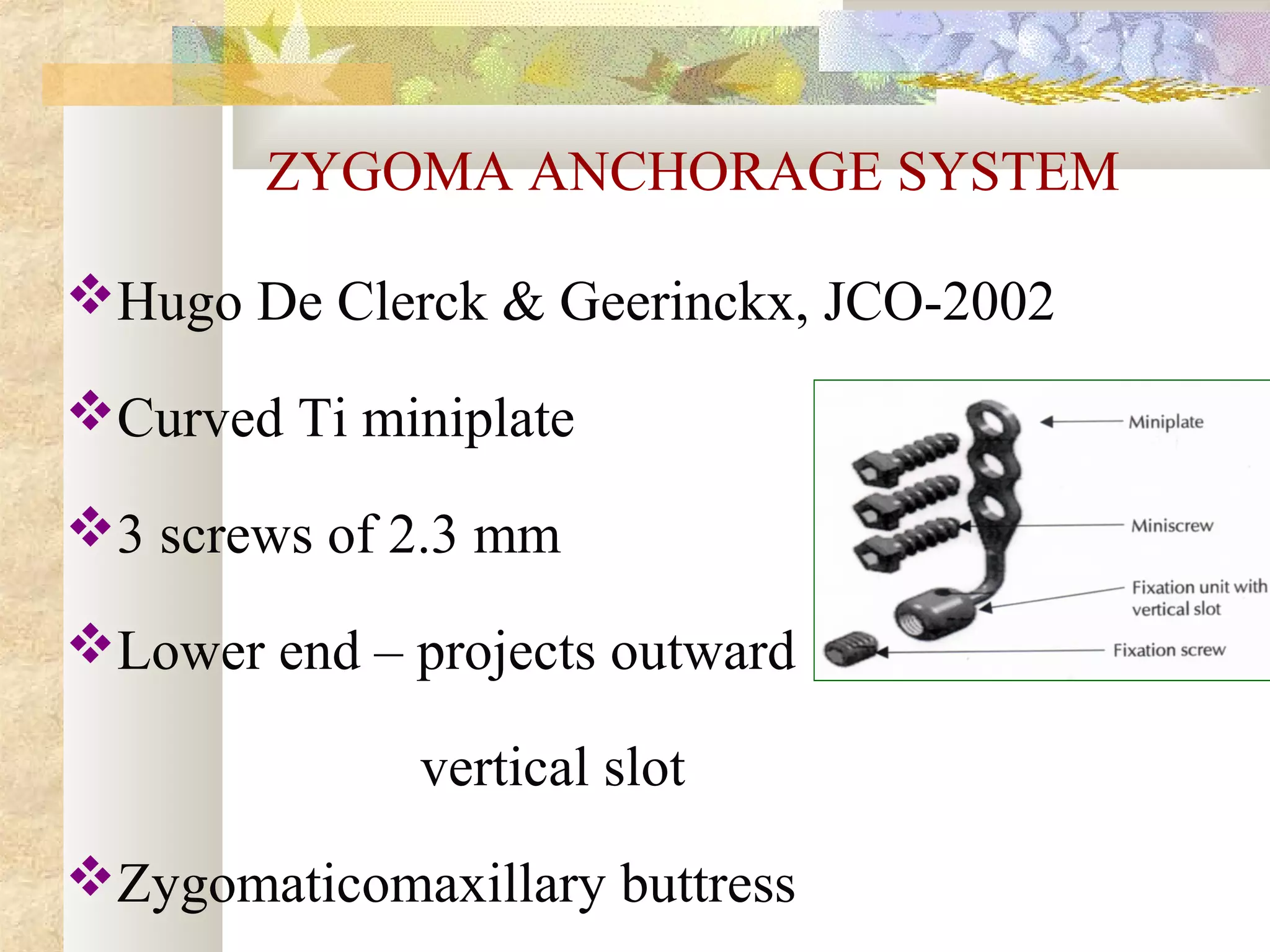
Zygoma anchorage system
BASED ON AREA OF PLACEMENT
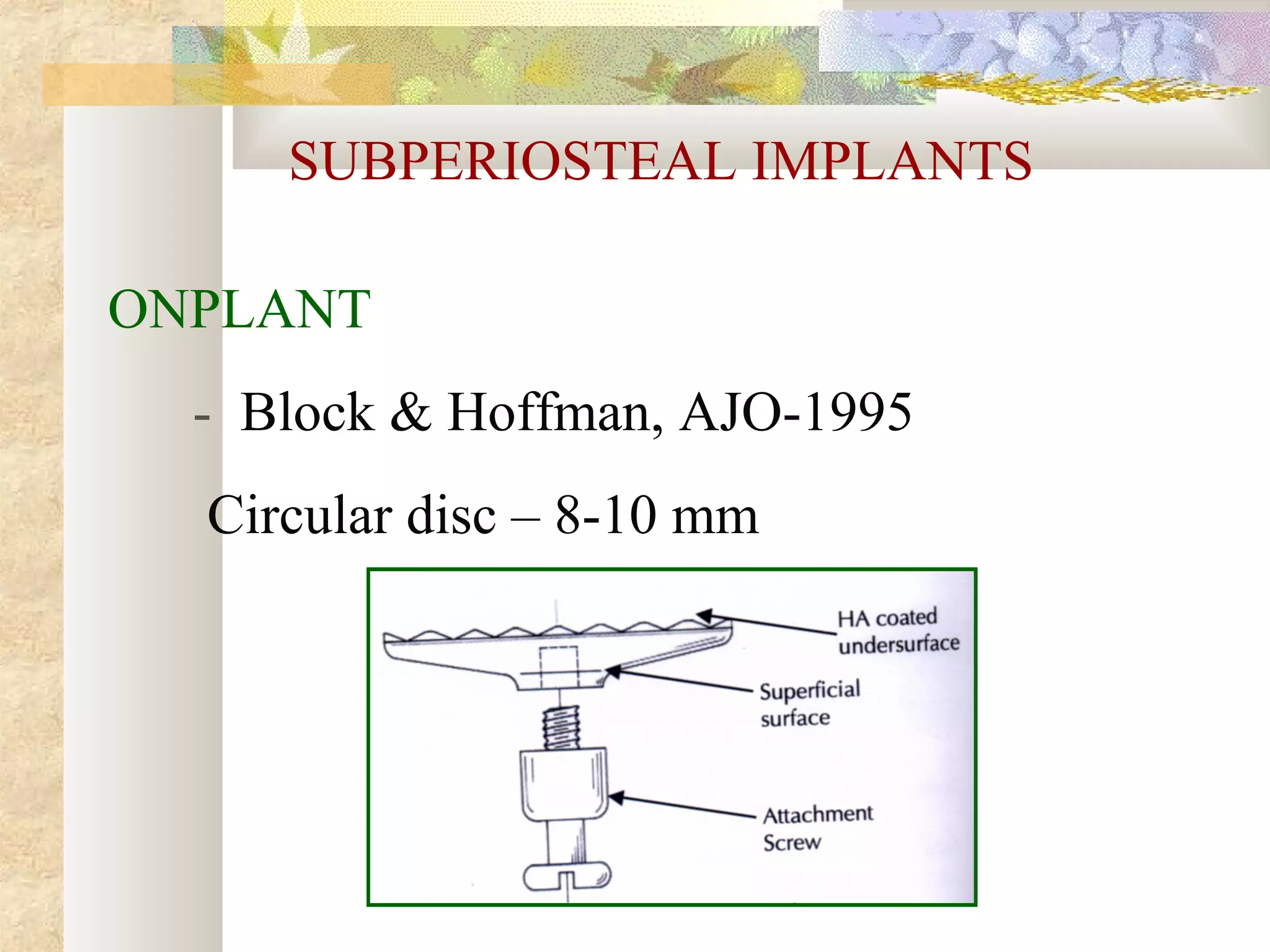
Subperiosteal implants
Osseous implants
Inter dental implants](https://image.slidesharecdn.com/differentanchoragesystemsinorthodontics-160506094138/75/Different-anchorage-systems-in-orthodontics-157-2048.jpg)


![OTHER INTERDENTAL SYSTEMS
Spider screw, Maino-JCO, 2003
OMAS [ orthodontic mini anchor
system]
JCO,2003](https://image.slidesharecdn.com/differentanchoragesystemsinorthodontics-160506094138/75/Different-anchorage-systems-in-orthodontics-167-2048.jpg)


The document discusses various anchorage systems in orthodontics, emphasizing the importance of controlling tooth movement while minimizing unwanted side effects. It categorizes types of anchorage into simple, stationary, reciprocal, and extraoral systems, detailing the factors affecting anchorage effectiveness. The document also covers techniques for force application and management across different orthodontic appliances, addressing clinical considerations for optimal treatment outcomes.


