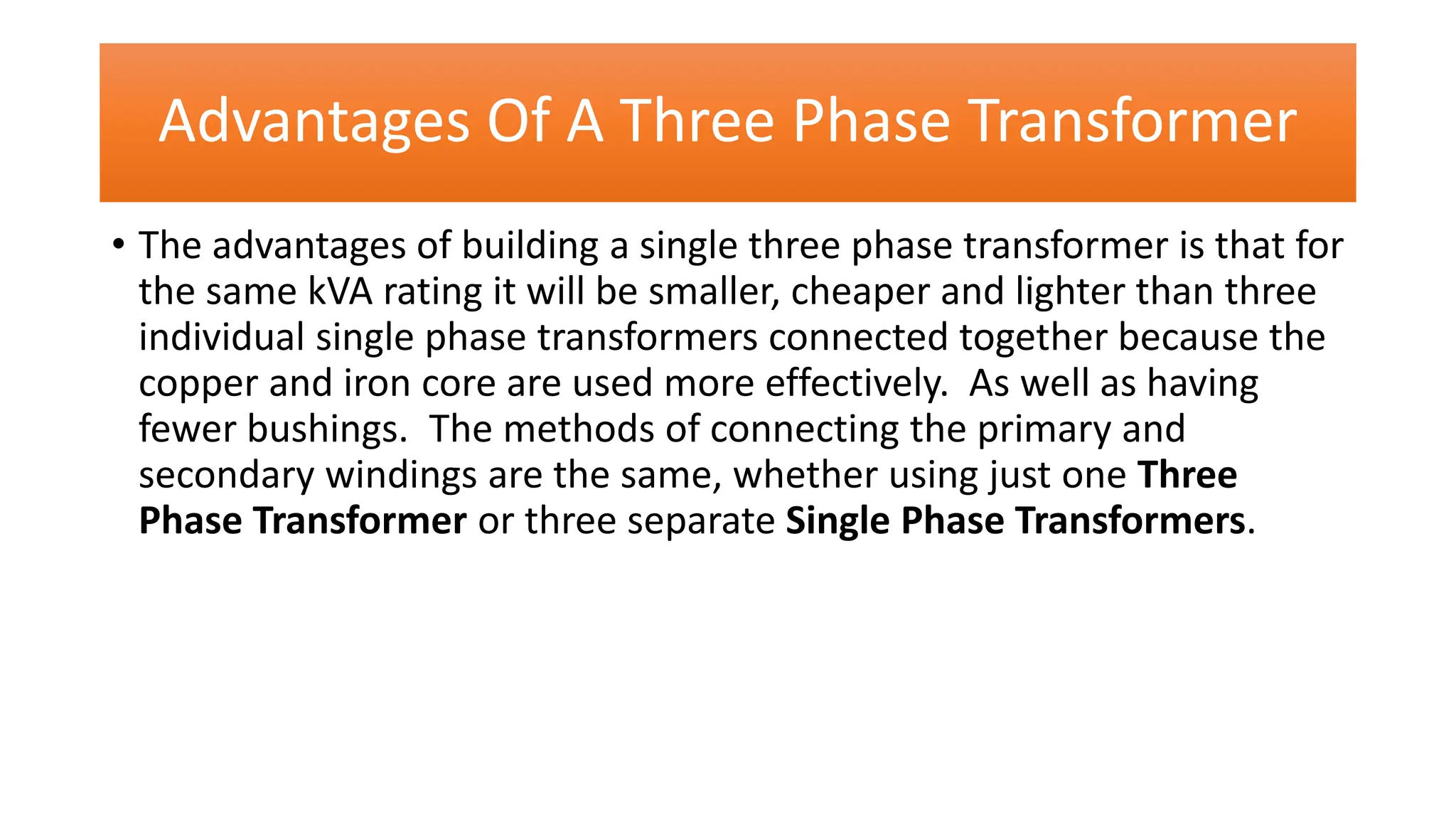
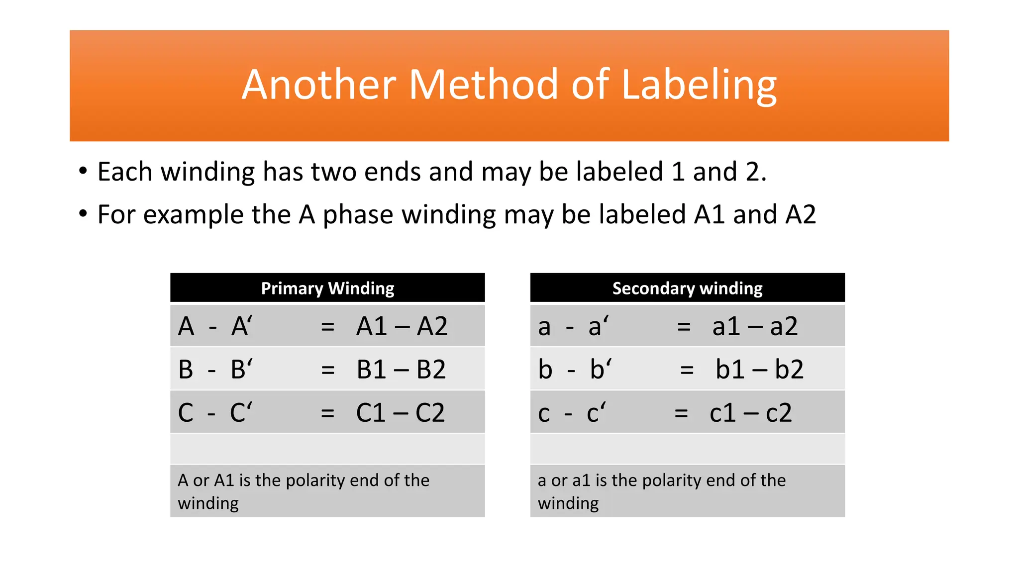
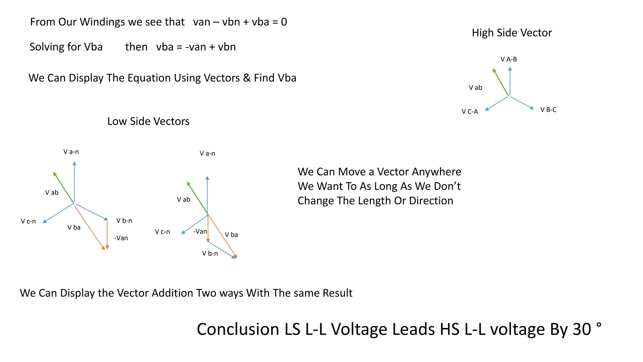
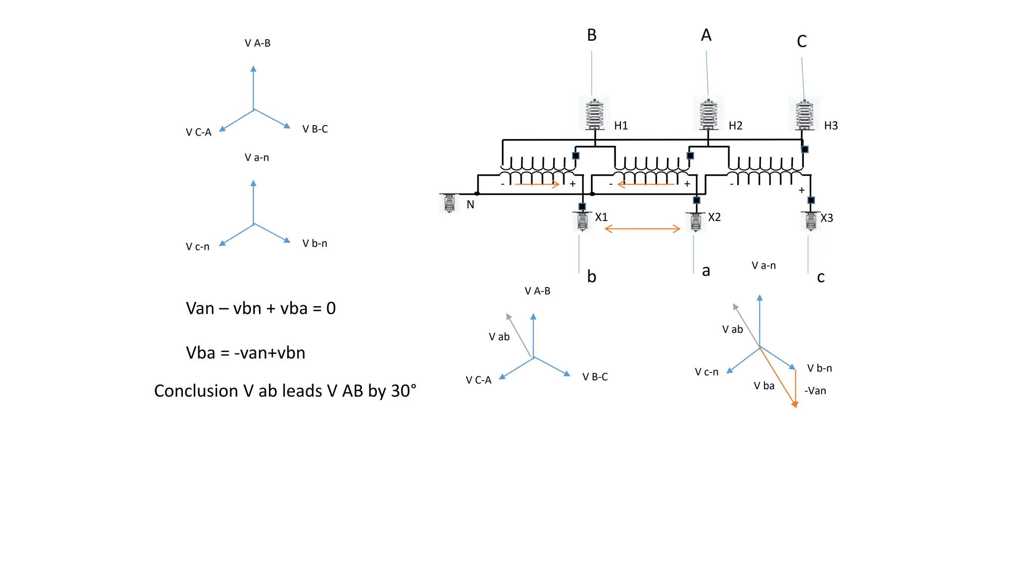
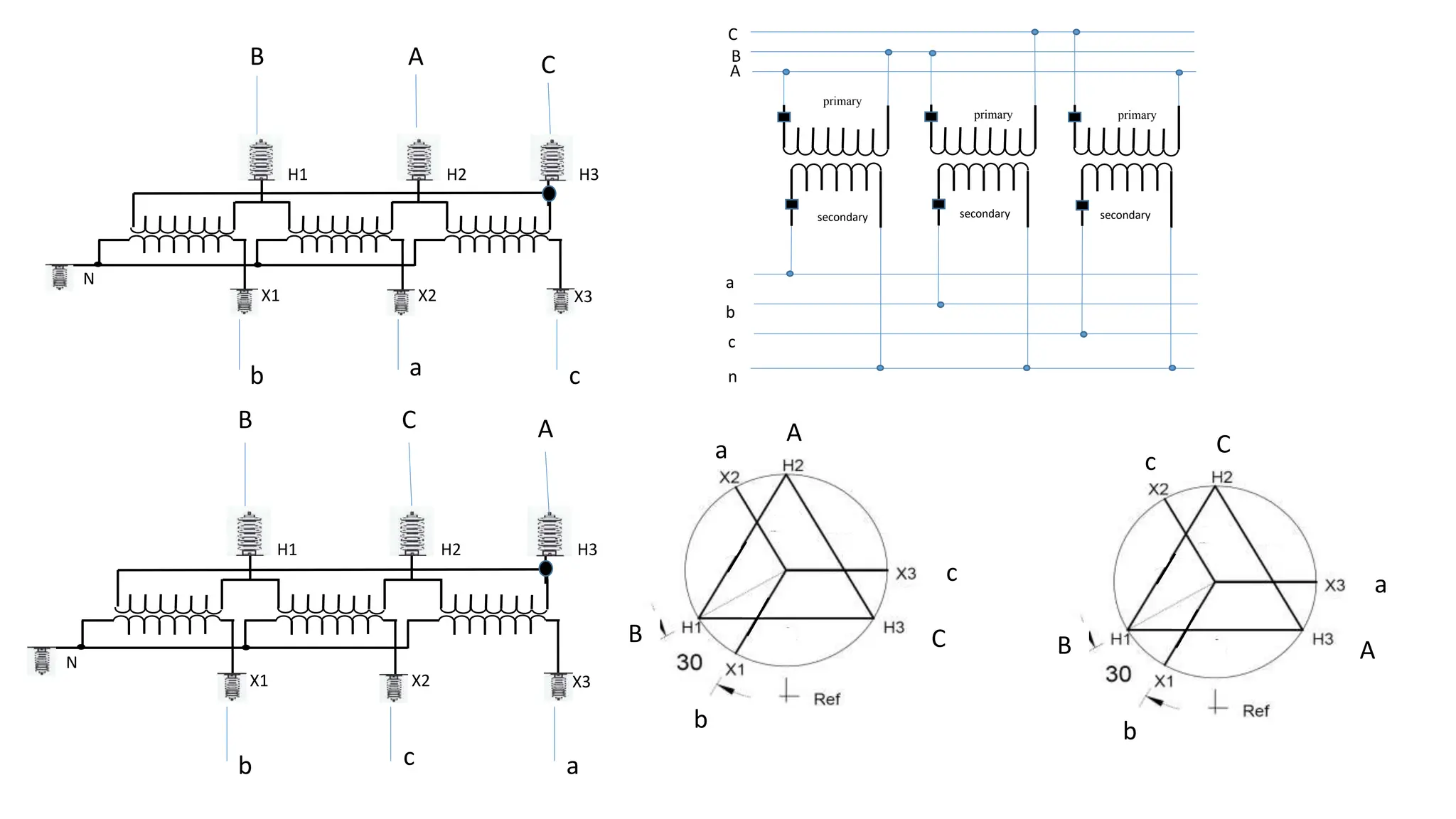
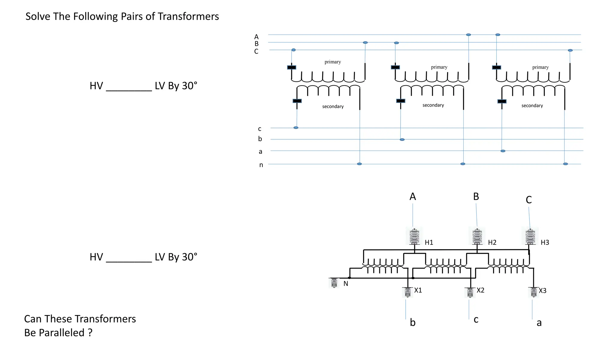
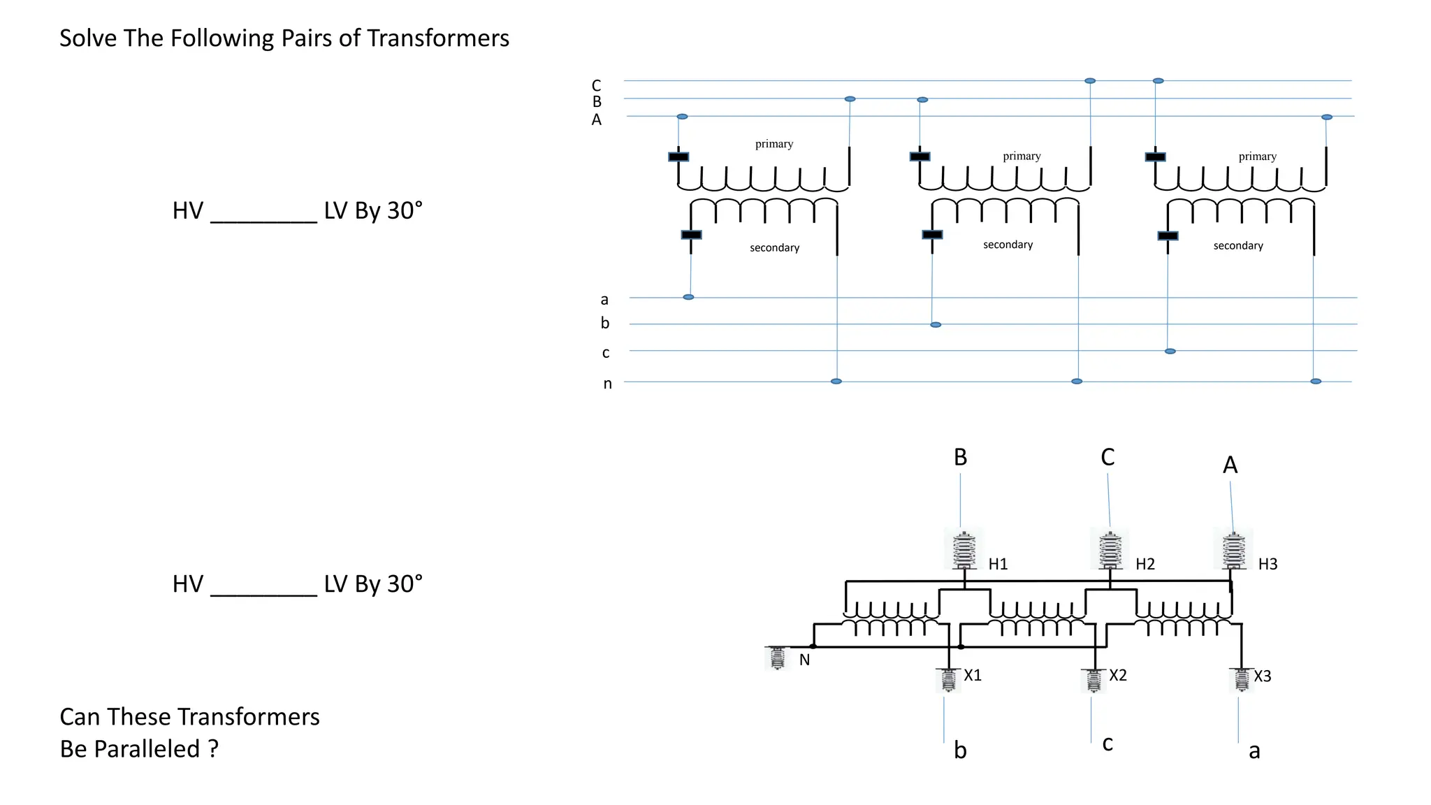
Determining Transformer
Phase Angle Displacement
Transformers Do Not Change Or Create
Phases
• A transformer can not act as a phase changing device and change
single-phase into three-phase or three-phase into single phase. To
make the transformer connections compatible with three-phase
supplies we need to connect them together in a particular way to
form a Three Phase Transformer Configuration.
• A three phase transformer or 3φ transformer can be constructed
either by connecting together three single-phase transformers,
thereby forming a so-called three phase transformer bank, or by using
one pre-assembled and balanced three phase transformer which
consists of three pairs of single phase windings mounted onto one
single laminated core.
Advantages Of A Three Phase Transformer
• The advantages of building a single three phase transformer is that for
the same kVA rating it will be smaller, cheaper and lighter than three
individual single phase transformers connected together because the
copper and iron core are used more effectively. As well as having
fewer bushings. The methods of connecting the primary and
secondary windings are the same, whether using just one Three
Phase Transformer or three separate Single Phase Transformers.
How We Label
• The standard method for marking three phase transformer windings
is to label the polarity end of three primary windings with capital
letters A, B and C, and the non polarity end of the winding as A´
(called A prime) B ´and C ´.
• The secondary windings are labeled with small (lower case) letters a,
b and c and a ´, b ´and c ´.
Another Method of Labeling
• Each winding has two ends and may be labeled 1 and 2.
• For example the A phase winding may be labeled A1 and A2
Primary Winding
A - A‘ = A1 – A2
B - B‘ = B1 – B2
C - C‘ = C1 – C2
A or A1 is the polarity end of the
winding
Secondary winding
a - a‘ = a1 – a2
b - b‘ = b1 – b2
c - c‘ = c1 – c2
a or a1 is the polarity end of the
winding
Phase Angle Displacement Between
Windings
•REMEMBER
• There is never any phase displacement or shift between two
windings
•REMEMBER
There MAY be a phase displacement or shift between the line
voltages of two transformers depending on how the windings are
connected
Winding Displacement Based on Connection
Type
Primary Secondary Displacement
Delta Wye 30°
Wye Delta 30°
Delta Delta None
Wye Wye None
Phase Angle Displacement Between
Transformer Banks
• To connect two transformers for parallel operation each transformer’s
line voltages must be in phase with the other transformer
• Transformers operating in parallel may be in the same substation
connected to the same bus or in substations at different locations
• If the voltages are not in phase with one another a fault condition will
exist when the connection is attempted
Delta - Wye Connection Displacement
•REMEMBER If one winding is connected ∆ and the other
winding connected Y there will always be a phase shift of 30 ⁰
between the line voltages
• Whether the shift is leading or lagging depends on how the ∆ is
closed
• If one transformer is leading and the other is lagging then the
associated phase voltages will have an angle of 60 ⁰ between them
Wye – Wye Transformers
• Wye – Wye transformers will have no phase angle shift between the
voltages on the primary and secondary
• Trying to connect a Δ – Y transformer to a Y- Y transformer will result
in a 30 ⁰ shift between the voltages on the secondary and they will
not connect
Standard Delta Connection
N
H1 H2 H3
X1 X2 X3
? ?
?
All Three Phase
Transformers will Have The
Delta Closed As Shown
Below
The Question Then
Becomes To which
Bushing Do We Connect
Our System Phases
Closing The Delta On Single Phase Banks
primary
secondary
primary
secondary
primary
secondary
A
a
B
C
b
c
n
We Can Close These Deltas Any Way We Wish But Will They
Connect to Other Transformers
primary
secondary
primary
secondary
primary
secondary
A
a
B
C
b
c
n
+ + +
- -
-
V A-B
V B-C
V C-A
V a-n
V b-n
V c-n
Van – vbn + vba = 0
primary
secondary
primary
secondary
primary
secondary
A
a
B
C
b
c
n
+ + +
- -
-
V A-B
V B-C
V C-A
V a-n
V b-n
V c-n
Van – vbn + vba = 0
Vba = -van+vbn
V a-n
V b-n
V c-n
-Van
V ba
V ab
High Side Vector
Low Side Vectors
V a-n
V b-n
V c-n -Van V ba
V ab
From Our Windings we see that van – vbn + vba = 0
Solving for Vba then vba = -van + vbn
We Can Display The Equation Using Vectors & Find Vba
We Can Display the Vector Addition Two ways With The same Result
V A-B
V B-C
V C-A
V ab
We Can Move a Vector Anywhere
We Want To As Long As We Don’t
Change The Length Or Direction
Conclusion LS L-L Voltage Leads HS L-L voltage By 30 °
N
H1 H2 H3
X1 X2 X3
A
B C
a
b c
V A-B
V B-C
V C-A
V a-n
V b-n
V c-n
+ +
+
-
- -
Van – vbn + vba = 0
Vba = -van+vbn
V a-n
V b-n
V c-n
-Van
V ba
V ab
V A-B
V B-C
V C-A
V ab
Conclusion V ab leads V AB by 30°
N
H1 H2 H3
X1 X2 X3
C
B A
c
b a
V A-C
V B-A
V C-B
V a-n
V b-n
V c-n
+ +
+
-
- -
Van – vcn + vca = 0
Vca = -van+vcn
V a-n
V b-n
V c-n
-Van
V ca
V ac
V A-B
V B-C
V C-A
V ac
Conclusion V ac lags V AC by 30°
Specification: Phasing
X1
X2
X3
H1
H2
H3
A
a
B
b
C
c
30
Ref
A B C
H1
S F
F
S
S
S F
F S
S F
F
H2
H3
N
X3
X2
X1
30° LEADING SECONDARY
ROTATION
COUNTERCLOCKWISE
H1
H2
H3 X1
X2
X3
Rotation
• Pick a fixed reference point
• Spin the circle such that the
H terminals pass the reference
point in the order 1-2-3
• CCW - Counterclockwise Rotation
if the circle rotates CCW
• CW - Clockwise Rotation
if the circle rotates CW
Displacement
• Pick a fixed reference point
• Spin the circle according to it’s
rotation from above
• Leading
If the X1 Terminal passes the
reference point before the H1
- Secondary leads the Primary
• Lagging
If the X1 Terminal passes the
reference point after the H1
- Secondary lags the Primary
• Displacement Angle
The angle between the H1 and
• X1 terminal
Reference Point
primary
secondary
primary
secondary
primary
secondary
A
a
B
C
b
c
n
N
H1 H2 H3
X1 X2 X3
A
B C
a
b c
N
H1 H2 H3
X1 X2 X3
C
B A
c
b a
A
B C
a
b
c
C
B A
c
b
a
primary
secondary
primary
secondary
primary
secondary
C
c
B
A
b
a
n
N
H1 H2 H3
X1 X2 X3
A
C B
c
b a
HV ________ LV By 30°
Can These Transformers
Be Paralleled ?
Solve The Following Pairs of Transformers
AØ
BØ
CØ
primary
secondary
primary
secondary
primary
secondary
C
c
B
A
b
a
n
N
H1 H2 H3
X1 X2 X3
B
A C
c
b a
HV ________ LV By 30°
Can These Transformers
Be Paralleled ?
Solve The Following Pairs of Transformers
primary
secondary
primary
secondary
primary
secondary
A
a
B
C
b
c
n
N
H1 H2 H3
X1 X2 X3
C
B A
c
b a
HV ________ LV By 30°
Can These Transformers
Be Paralleled ?
Solve The Following Pairs of Transformers
primary
secondary
primary
secondary
primary
secondary
A
a
B
C
b
c
n
N
H1 H2 H3
X1 X2 X3
A
C B
a
c b
HV ________ LV By 30°
Can These Transformers
Be Paralleled ?
Solve The Following Pairs of Transformers
primary
secondary
primary
secondary
primary
secondary
A
a
B
C
b
c
n
N
H1 H2 H3
X1 X2 X3
A
C B
a
c b
HV ________ LV By 30°
Can These Transformers
Be Paralleled ?
Solve The Following Pairs of Transformers
N
H1 H2 H3
X1 X2 X3
B
C A
b
c a
Fig. 1
N
H1 H2 H3
X1 X2 X3
A
B C
a
b c
Fig. 3
primary
secondary
primary
secondary
primary
secondary
C
n
B
A
a
b
c
Fig. 2
AØ BØ CØ
Practice 1
N
H1 H2 H3
X1 X2 X3
B
C A
b
c a
Fig. 1
N
H1 H2 H3
X1 X2 X3
A
B C
a
b c
Fig. 3
primary
secondary
primary
secondary
primary
secondary
C
n
B
A
a
b
c
Fig. 2
AØ BØ CØ
V A-B
V B-C
V C-A
V ab
Solution
Practice 1 Solution
V a-n
V b-n
V c-n
-Van
V ba
V ab
N
H1 H2 H3
X1 X2 X3
B
A C
b
a c
Fig. 3
primary
secondary
primary
secondary
primary
secondary
C
n
B
A
a
b
c
Fig. 2
AØ BØ CØ
primary
secondary
primary
secondary
primary
secondary
C
n
B
A
a
b
c
Fig. 2
AØ BØ CØ
Practice 2
N
H1 H2 H3
X1 X2 X3
B
A C
b
a c
Fig. 8
primary
secondary
primary
secondary
primary
secondary
C
n
B
A
a
b
c
Fig.6
AØ BØ CØ
primary
secondary
primary
secondary
primary
secondary
C
n
B
A
a
b
c
Fig. 7
AØ BØ CØ
V a-n
V b-n
V c-n
-Van
V ca
V ac
V A-C
V B-A
V C-B
V ac
Practice 2 Solution
N
H1 H2 H3
X1 X2 X3
Fig. 8
Does HV Lead or Lag LV?
N
H1 H2 H3
X1 X2 X3
Fig. 8
Does HV Lead or Lag LV?
V x1-n
V x2-n
-V x1
V x3-x1
V x1-x2
V x3-n
V x1-x3
V H1-H3
V H2-H1
V H3-H2
V x1-x3
Lets Keep it Simple
• If a transformer bank is connect so that the polarity of the any
winding is connected to AØ and the non-polarity of the same winding
is connected to CØ then the HS L-L voltage leads the LS L-L voltage by
30°
• A-Cʹ then HS leads
• If a transformer bank is connect so that the polarity of the any
winding is connected to AØ and the non-polarity of the same winding
is connected to BØ then the HS L-L voltage lags the LS L-L voltage by
30°
• A-Bʹ then HS lags

Determining Transformer Phase Angle Displacement.pptx

  • 1.
  • 2.
    Transformers Do NotChange Or Create Phases • A transformer can not act as a phase changing device and change single-phase into three-phase or three-phase into single phase. To make the transformer connections compatible with three-phase supplies we need to connect them together in a particular way to form a Three Phase Transformer Configuration. • A three phase transformer or 3φ transformer can be constructed either by connecting together three single-phase transformers, thereby forming a so-called three phase transformer bank, or by using one pre-assembled and balanced three phase transformer which consists of three pairs of single phase windings mounted onto one single laminated core.
  • 3.
    Advantages Of AThree Phase Transformer • The advantages of building a single three phase transformer is that for the same kVA rating it will be smaller, cheaper and lighter than three individual single phase transformers connected together because the copper and iron core are used more effectively. As well as having fewer bushings. The methods of connecting the primary and secondary windings are the same, whether using just one Three Phase Transformer or three separate Single Phase Transformers.
  • 4.
    How We Label •The standard method for marking three phase transformer windings is to label the polarity end of three primary windings with capital letters A, B and C, and the non polarity end of the winding as A´ (called A prime) B ´and C ´. • The secondary windings are labeled with small (lower case) letters a, b and c and a ´, b ´and c ´.
  • 5.
    Another Method ofLabeling • Each winding has two ends and may be labeled 1 and 2. • For example the A phase winding may be labeled A1 and A2 Primary Winding A - A‘ = A1 – A2 B - B‘ = B1 – B2 C - C‘ = C1 – C2 A or A1 is the polarity end of the winding Secondary winding a - a‘ = a1 – a2 b - b‘ = b1 – b2 c - c‘ = c1 – c2 a or a1 is the polarity end of the winding
  • 6.
    Phase Angle DisplacementBetween Windings •REMEMBER • There is never any phase displacement or shift between two windings •REMEMBER There MAY be a phase displacement or shift between the line voltages of two transformers depending on how the windings are connected
  • 7.
    Winding Displacement Basedon Connection Type Primary Secondary Displacement Delta Wye 30° Wye Delta 30° Delta Delta None Wye Wye None
  • 8.
    Phase Angle DisplacementBetween Transformer Banks • To connect two transformers for parallel operation each transformer’s line voltages must be in phase with the other transformer • Transformers operating in parallel may be in the same substation connected to the same bus or in substations at different locations • If the voltages are not in phase with one another a fault condition will exist when the connection is attempted
  • 9.
    Delta - WyeConnection Displacement •REMEMBER If one winding is connected ∆ and the other winding connected Y there will always be a phase shift of 30 ⁰ between the line voltages • Whether the shift is leading or lagging depends on how the ∆ is closed • If one transformer is leading and the other is lagging then the associated phase voltages will have an angle of 60 ⁰ between them
  • 10.
    Wye – WyeTransformers • Wye – Wye transformers will have no phase angle shift between the voltages on the primary and secondary • Trying to connect a Δ – Y transformer to a Y- Y transformer will result in a 30 ⁰ shift between the voltages on the secondary and they will not connect
  • 11.
    Standard Delta Connection N H1H2 H3 X1 X2 X3 ? ? ? All Three Phase Transformers will Have The Delta Closed As Shown Below The Question Then Becomes To which Bushing Do We Connect Our System Phases
  • 12.
    Closing The DeltaOn Single Phase Banks primary secondary primary secondary primary secondary A a B C b c n We Can Close These Deltas Any Way We Wish But Will They Connect to Other Transformers
  • 13.
    primary secondary primary secondary primary secondary A a B C b c n + + + -- - V A-B V B-C V C-A V a-n V b-n V c-n Van – vbn + vba = 0
  • 14.
    primary secondary primary secondary primary secondary A a B C b c n + + + -- - V A-B V B-C V C-A V a-n V b-n V c-n Van – vbn + vba = 0 Vba = -van+vbn
  • 15.
    V a-n V b-n Vc-n -Van V ba V ab High Side Vector Low Side Vectors V a-n V b-n V c-n -Van V ba V ab From Our Windings we see that van – vbn + vba = 0 Solving for Vba then vba = -van + vbn We Can Display The Equation Using Vectors & Find Vba We Can Display the Vector Addition Two ways With The same Result V A-B V B-C V C-A V ab We Can Move a Vector Anywhere We Want To As Long As We Don’t Change The Length Or Direction Conclusion LS L-L Voltage Leads HS L-L voltage By 30 °
  • 16.
    N H1 H2 H3 X1X2 X3 A B C a b c V A-B V B-C V C-A V a-n V b-n V c-n + + + - - - Van – vbn + vba = 0 Vba = -van+vbn V a-n V b-n V c-n -Van V ba V ab V A-B V B-C V C-A V ab Conclusion V ab leads V AB by 30°
  • 17.
    N H1 H2 H3 X1X2 X3 C B A c b a V A-C V B-A V C-B V a-n V b-n V c-n + + + - - - Van – vcn + vca = 0 Vca = -van+vcn V a-n V b-n V c-n -Van V ca V ac V A-B V B-C V C-A V ac Conclusion V ac lags V AC by 30°
  • 18.
    Specification: Phasing X1 X2 X3 H1 H2 H3 A a B b C c 30 Ref A BC H1 S F F S S S F F S S F F H2 H3 N X3 X2 X1 30° LEADING SECONDARY ROTATION COUNTERCLOCKWISE H1 H2 H3 X1 X2 X3 Rotation • Pick a fixed reference point • Spin the circle such that the H terminals pass the reference point in the order 1-2-3 • CCW - Counterclockwise Rotation if the circle rotates CCW • CW - Clockwise Rotation if the circle rotates CW Displacement • Pick a fixed reference point • Spin the circle according to it’s rotation from above • Leading If the X1 Terminal passes the reference point before the H1 - Secondary leads the Primary • Lagging If the X1 Terminal passes the reference point after the H1 - Secondary lags the Primary • Displacement Angle The angle between the H1 and • X1 terminal Reference Point
  • 19.
    primary secondary primary secondary primary secondary A a B C b c n N H1 H2 H3 X1X2 X3 A B C a b c N H1 H2 H3 X1 X2 X3 C B A c b a A B C a b c C B A c b a
  • 20.
    primary secondary primary secondary primary secondary C c B A b a n N H1 H2 H3 X1X2 X3 A C B c b a HV ________ LV By 30° HV ________ LV By 30° Can These Transformers Be Paralleled ? Solve The Following Pairs of Transformers AØ BØ CØ
  • 21.
    primary secondary primary secondary primary secondary C c B A b a n N H1 H2 H3 X1X2 X3 B A C c b a HV ________ LV By 30° HV ________ LV By 30° Can These Transformers Be Paralleled ? Solve The Following Pairs of Transformers
  • 22.
    primary secondary primary secondary primary secondary A a B C b c n N H1 H2 H3 X1X2 X3 C B A c b a HV ________ LV By 30° HV ________ LV By 30° Can These Transformers Be Paralleled ? Solve The Following Pairs of Transformers
  • 23.
    primary secondary primary secondary primary secondary A a B C b c n N H1 H2 H3 X1X2 X3 A C B a c b HV ________ LV By 30° HV ________ LV By 30° Can These Transformers Be Paralleled ? Solve The Following Pairs of Transformers
  • 24.
    primary secondary primary secondary primary secondary A a B C b c n N H1 H2 H3 X1X2 X3 A C B a c b HV ________ LV By 30° HV ________ LV By 30° Can These Transformers Be Paralleled ? Solve The Following Pairs of Transformers
  • 25.
    N H1 H2 H3 X1X2 X3 B C A b c a Fig. 1 N H1 H2 H3 X1 X2 X3 A B C a b c Fig. 3 primary secondary primary secondary primary secondary C n B A a b c Fig. 2 AØ BØ CØ Practice 1
  • 26.
    N H1 H2 H3 X1X2 X3 B C A b c a Fig. 1 N H1 H2 H3 X1 X2 X3 A B C a b c Fig. 3 primary secondary primary secondary primary secondary C n B A a b c Fig. 2 AØ BØ CØ V A-B V B-C V C-A V ab Solution Practice 1 Solution V a-n V b-n V c-n -Van V ba V ab
  • 27.
    N H1 H2 H3 X1X2 X3 B A C b a c Fig. 3 primary secondary primary secondary primary secondary C n B A a b c Fig. 2 AØ BØ CØ primary secondary primary secondary primary secondary C n B A a b c Fig. 2 AØ BØ CØ Practice 2
  • 28.
    N H1 H2 H3 X1X2 X3 B A C b a c Fig. 8 primary secondary primary secondary primary secondary C n B A a b c Fig.6 AØ BØ CØ primary secondary primary secondary primary secondary C n B A a b c Fig. 7 AØ BØ CØ V a-n V b-n V c-n -Van V ca V ac V A-C V B-A V C-B V ac Practice 2 Solution
  • 29.
    N H1 H2 H3 X1X2 X3 Fig. 8 Does HV Lead or Lag LV?
  • 30.
    N H1 H2 H3 X1X2 X3 Fig. 8 Does HV Lead or Lag LV? V x1-n V x2-n -V x1 V x3-x1 V x1-x2 V x3-n V x1-x3 V H1-H3 V H2-H1 V H3-H2 V x1-x3
  • 31.
    Lets Keep itSimple • If a transformer bank is connect so that the polarity of the any winding is connected to AØ and the non-polarity of the same winding is connected to CØ then the HS L-L voltage leads the LS L-L voltage by 30° • A-Cʹ then HS leads • If a transformer bank is connect so that the polarity of the any winding is connected to AØ and the non-polarity of the same winding is connected to BØ then the HS L-L voltage lags the LS L-L voltage by 30° • A-Bʹ then HS lags

Editor's Notes