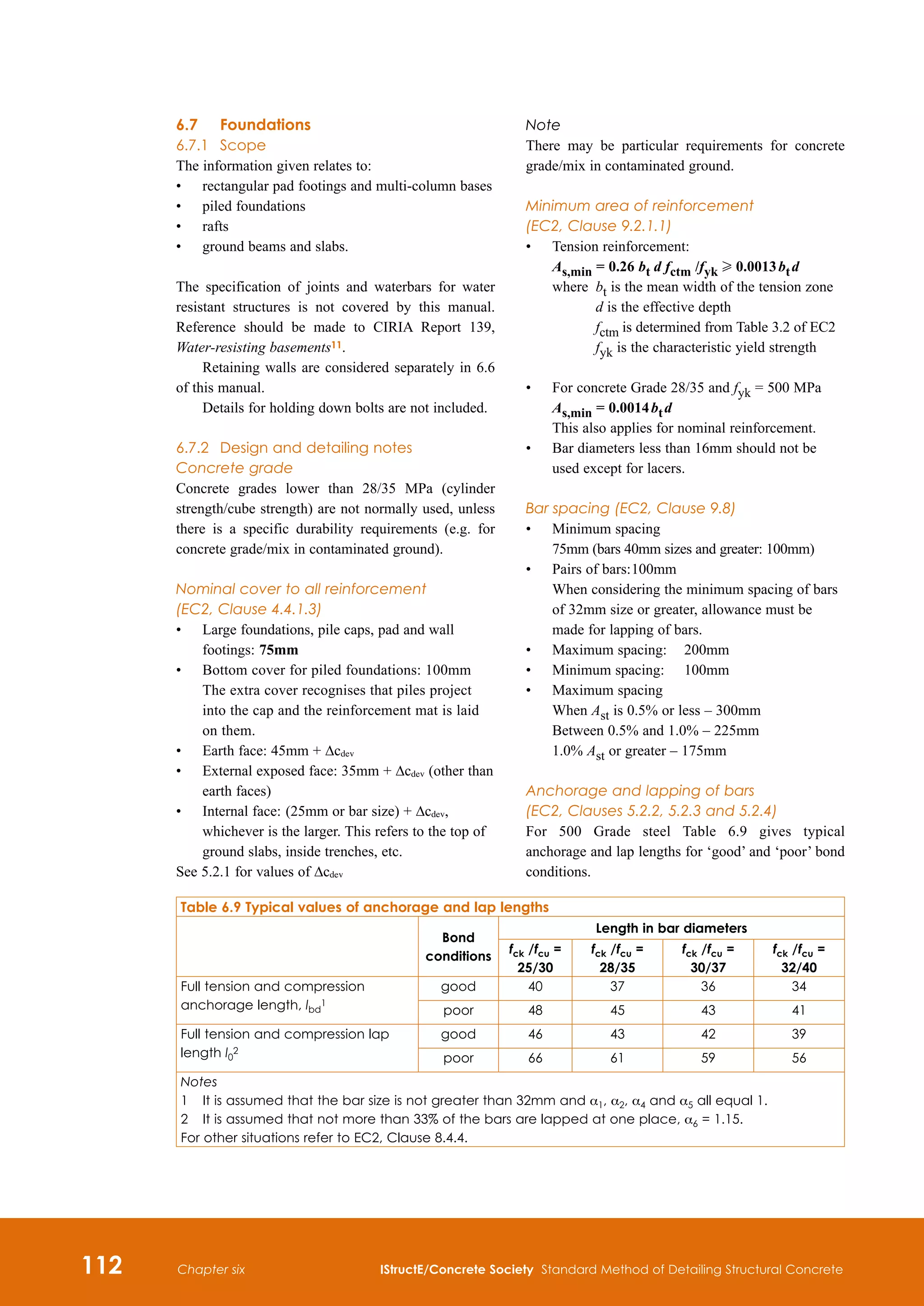
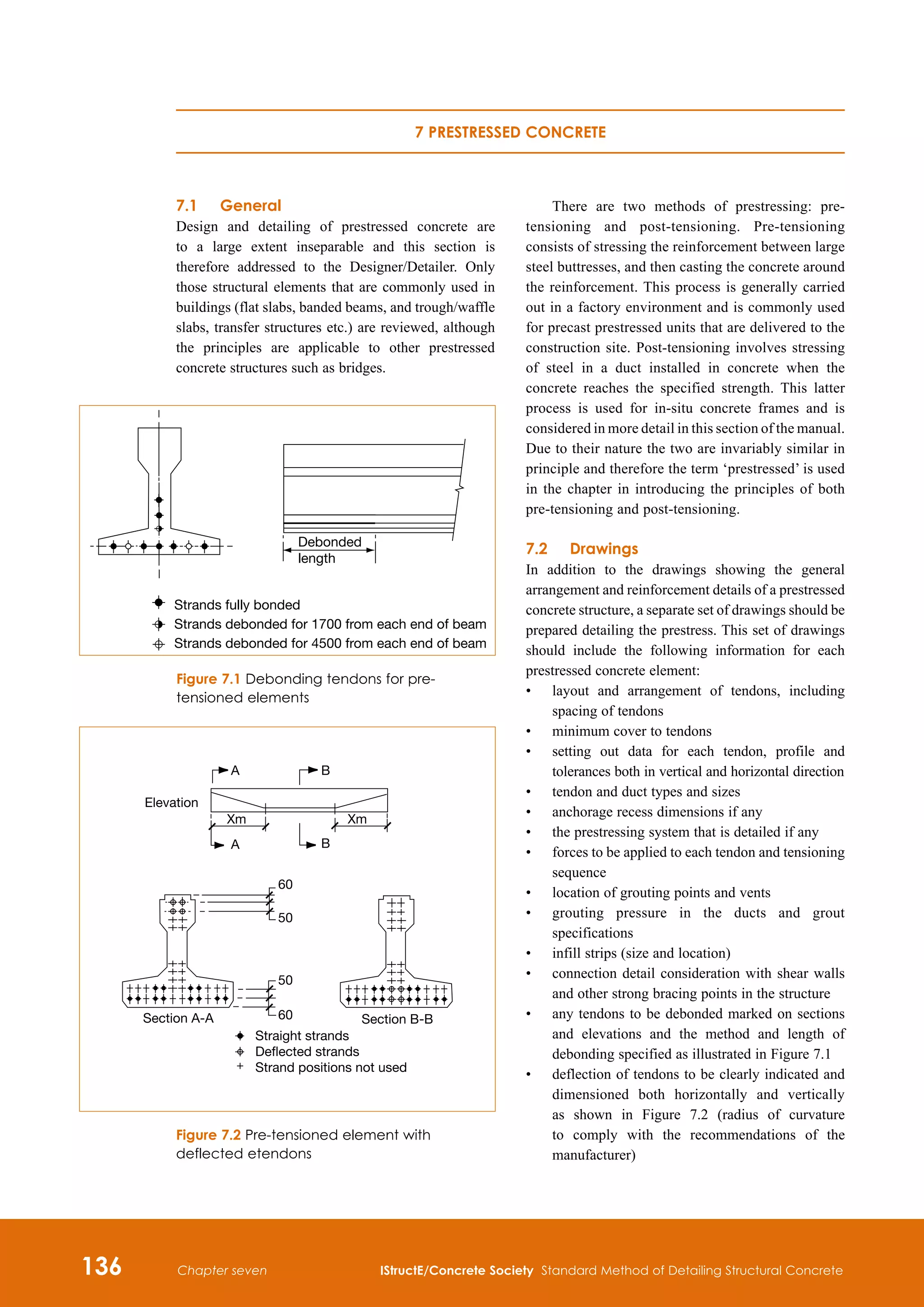
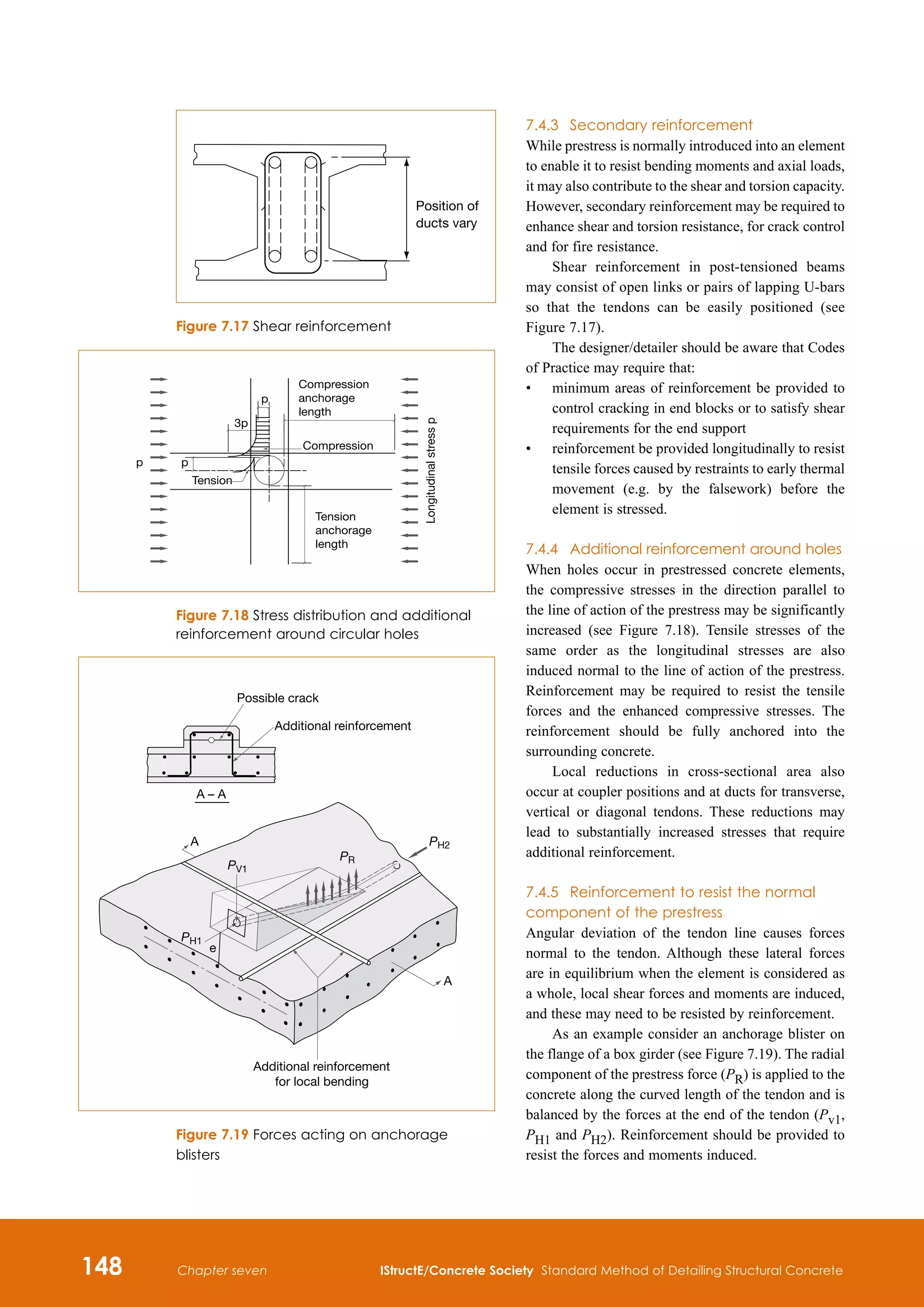
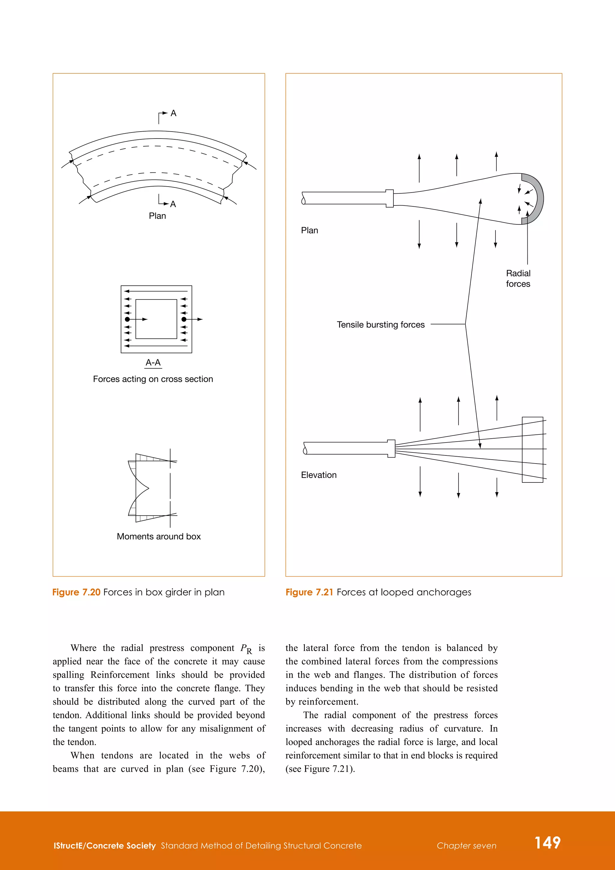
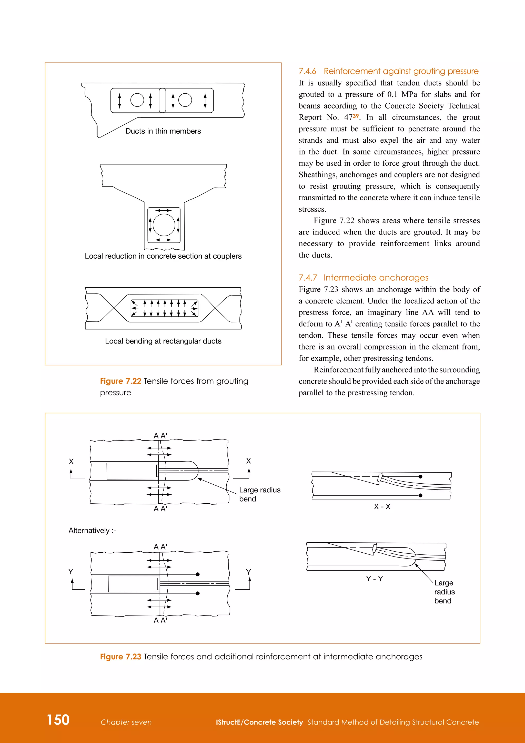
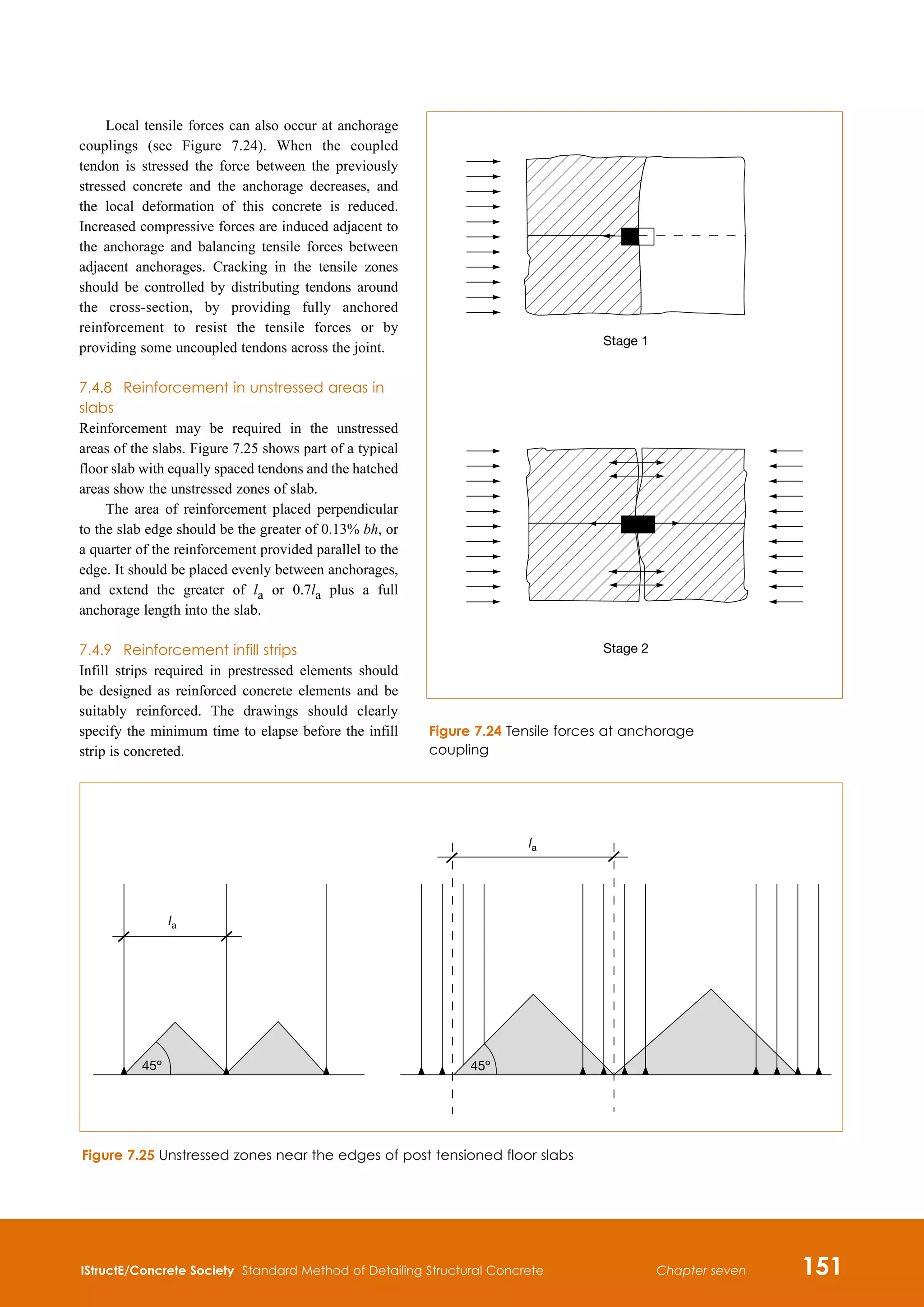
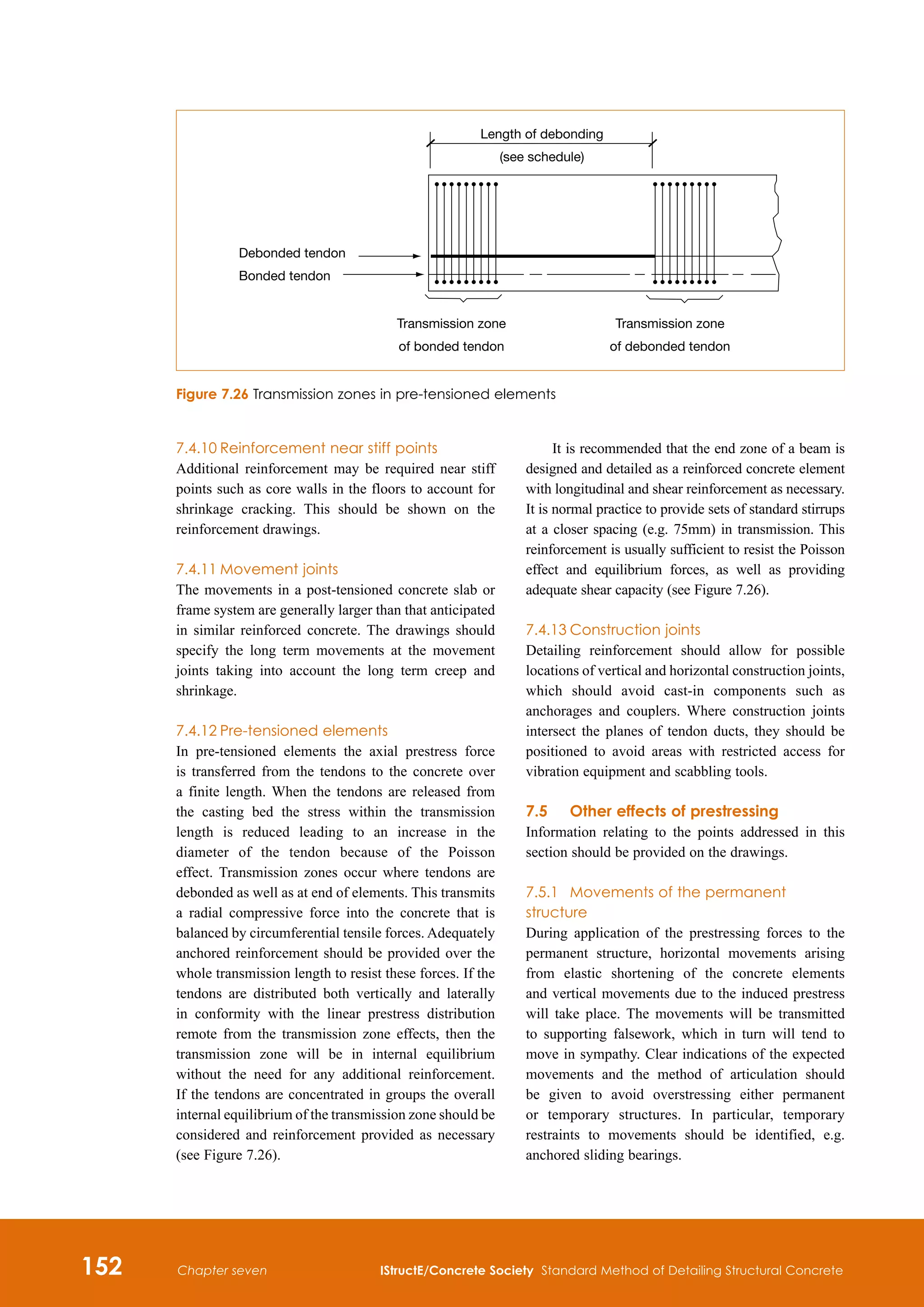
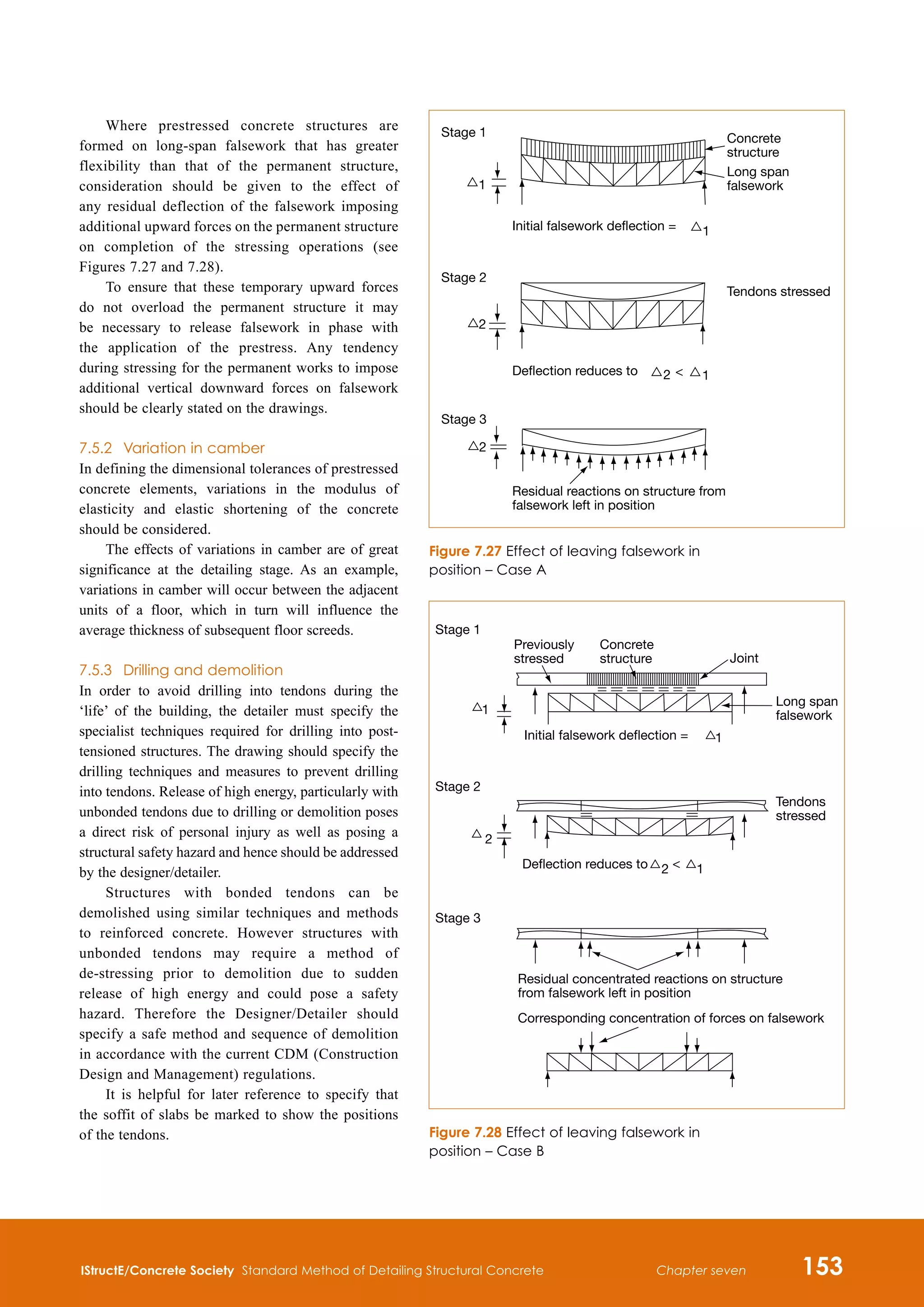
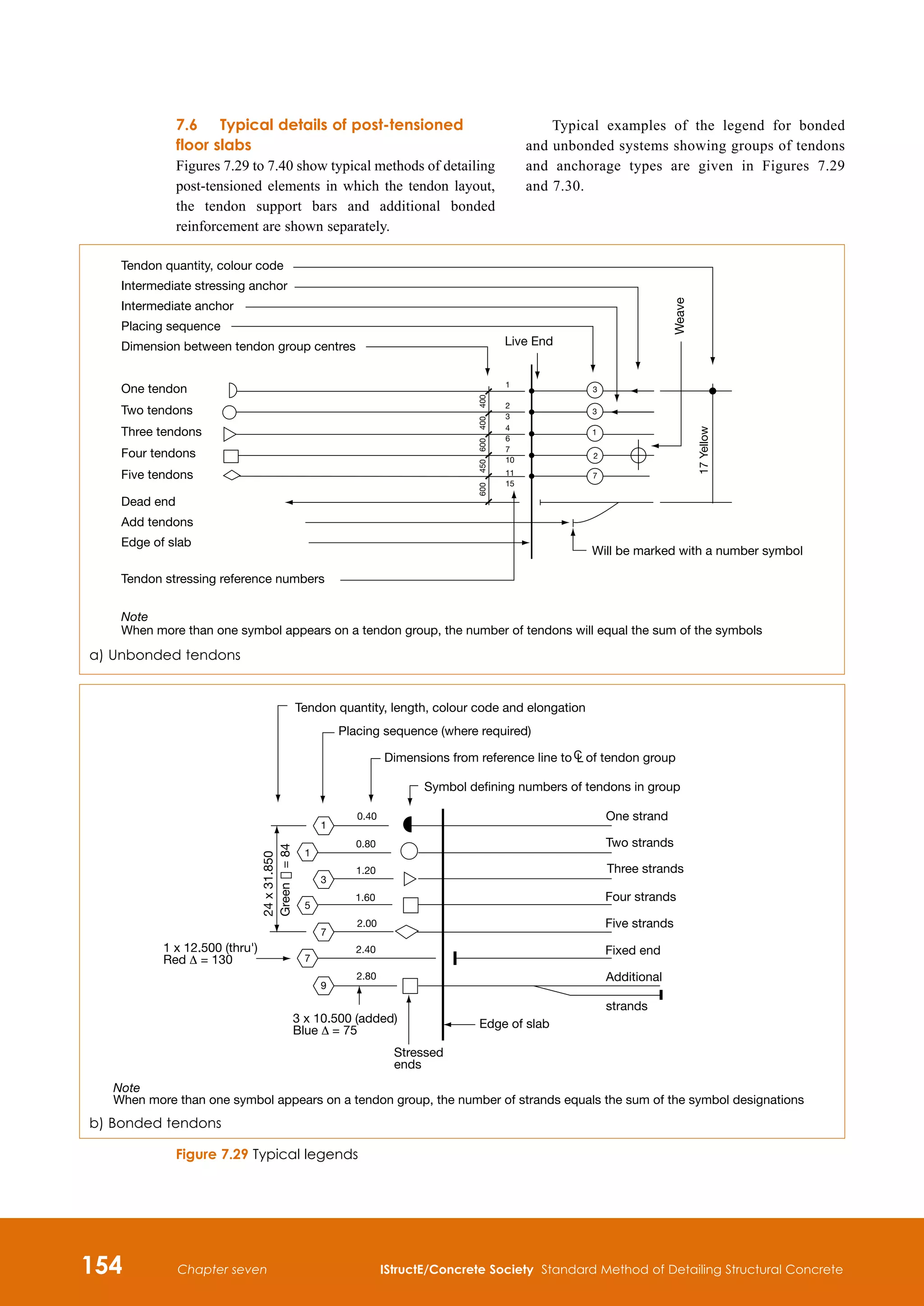
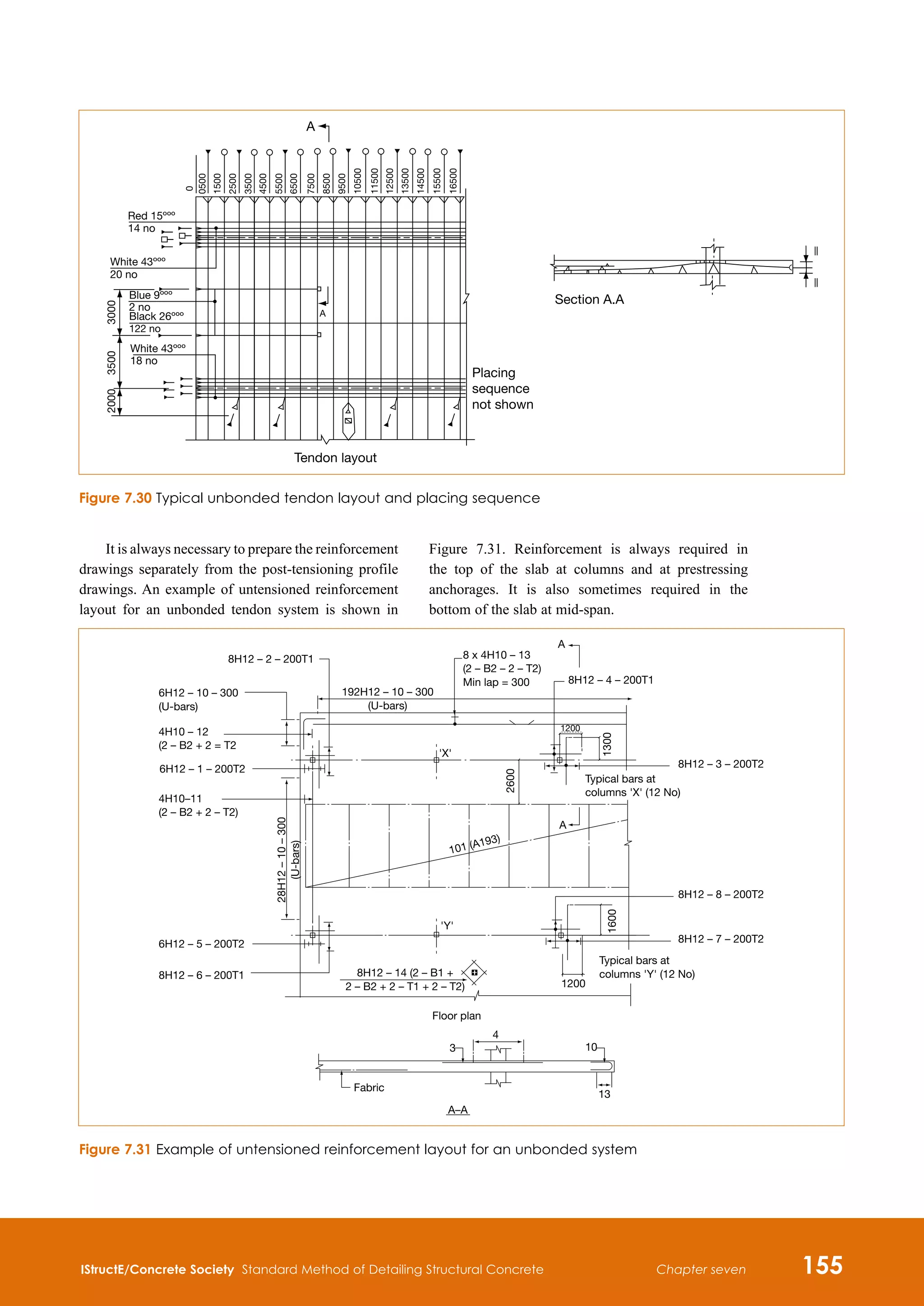
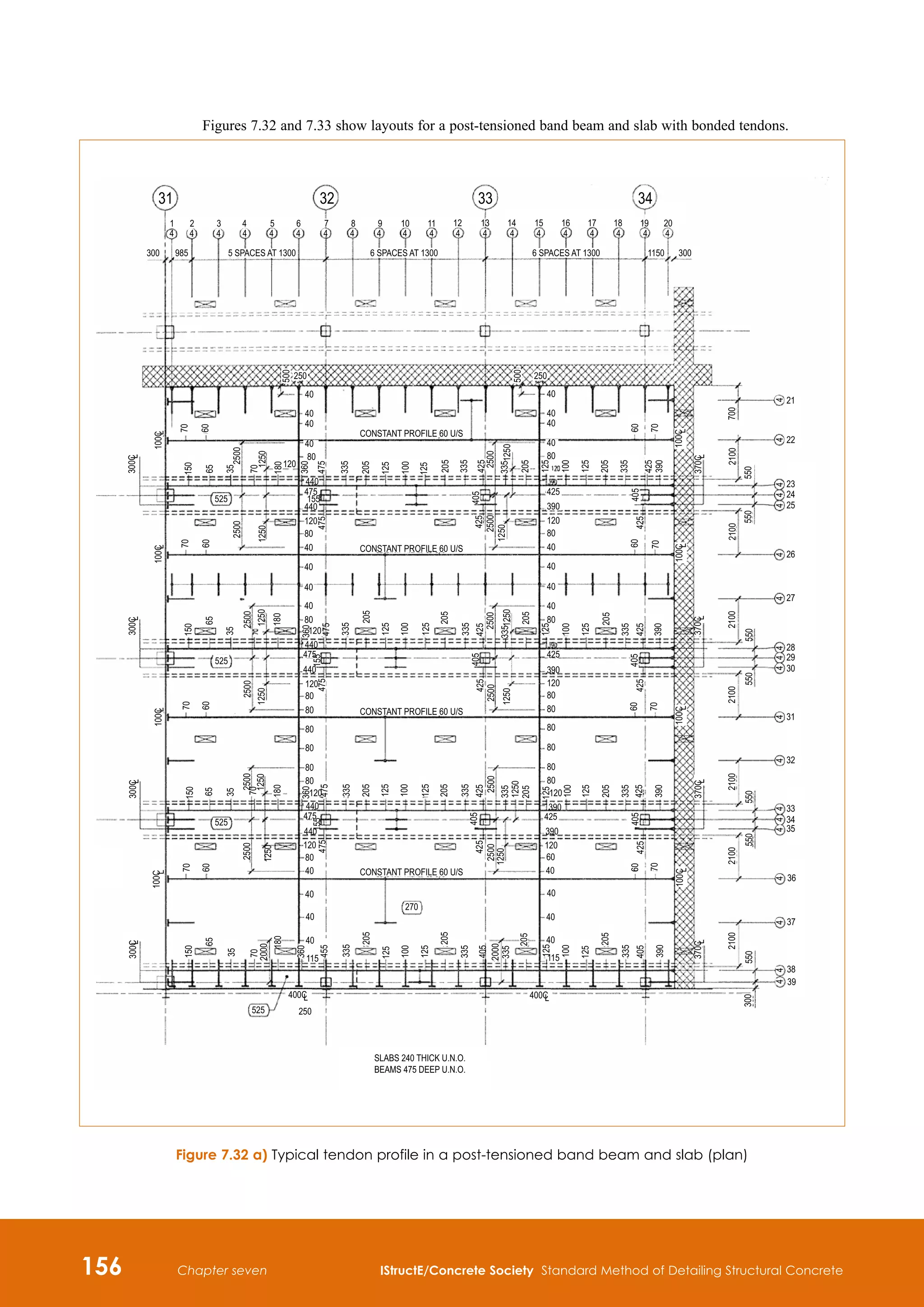
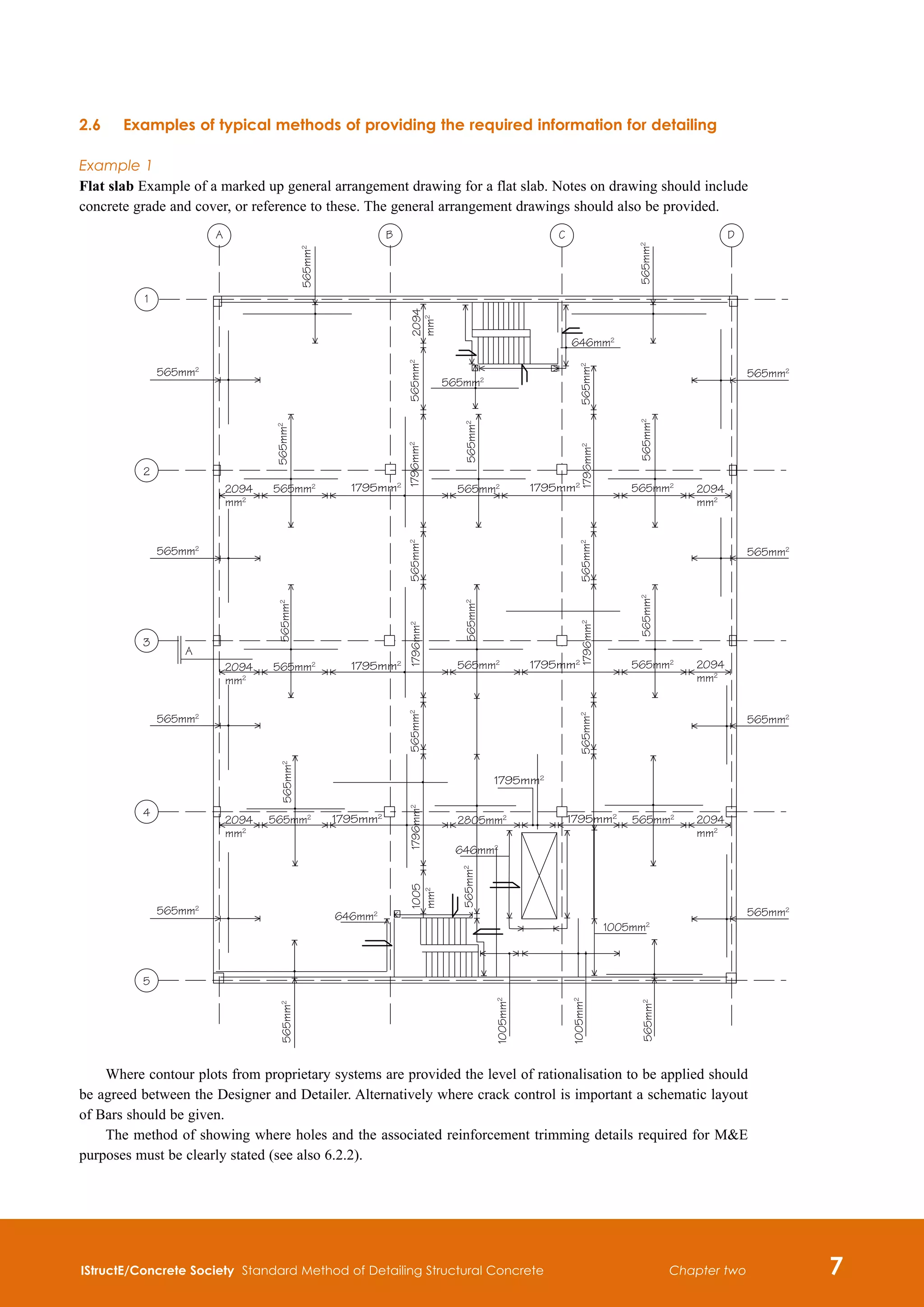
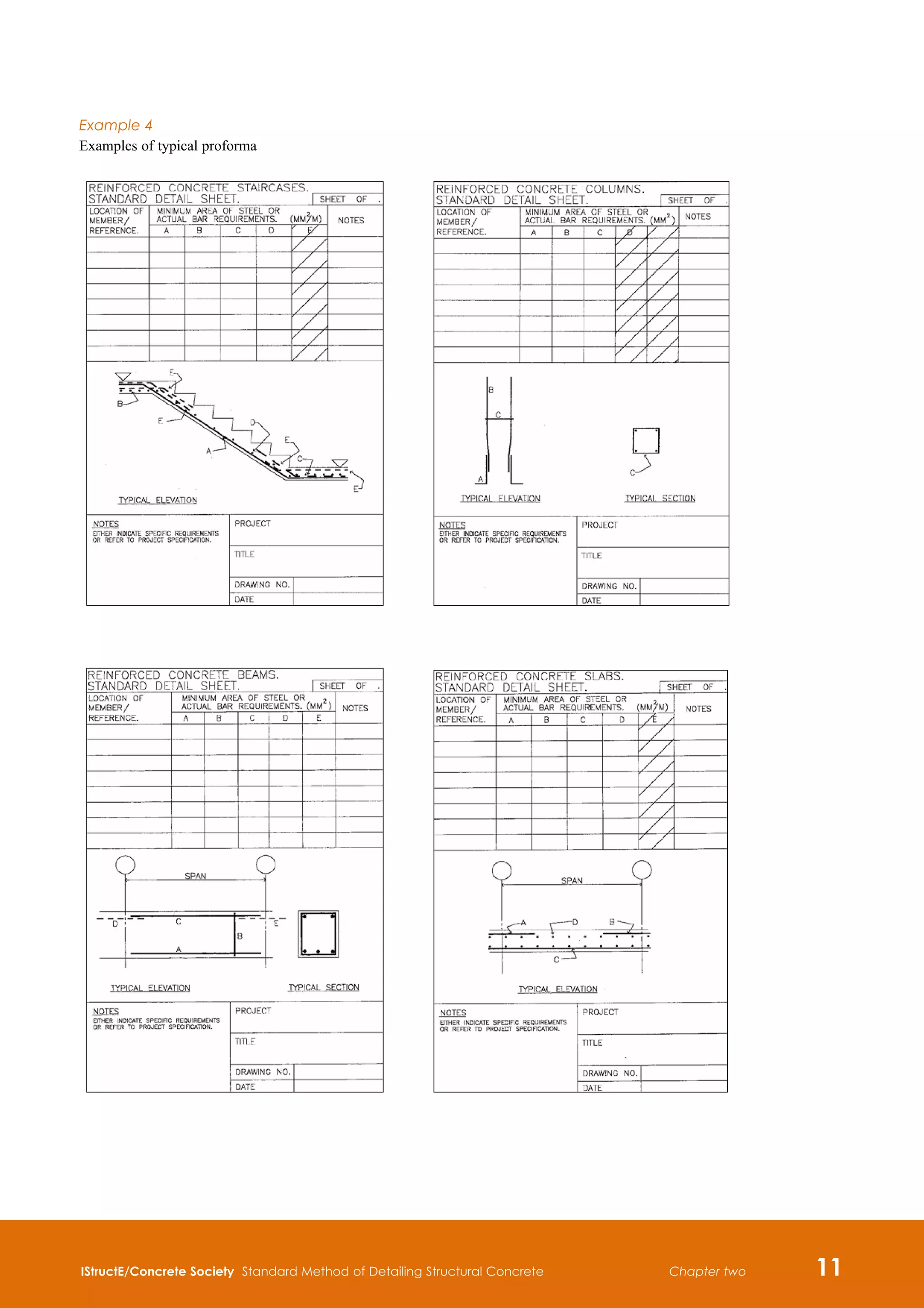
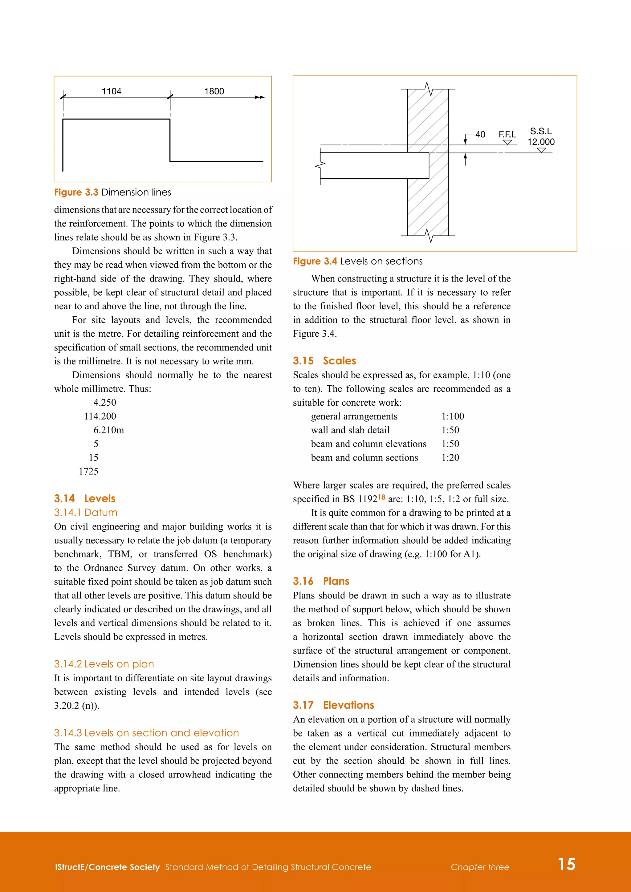
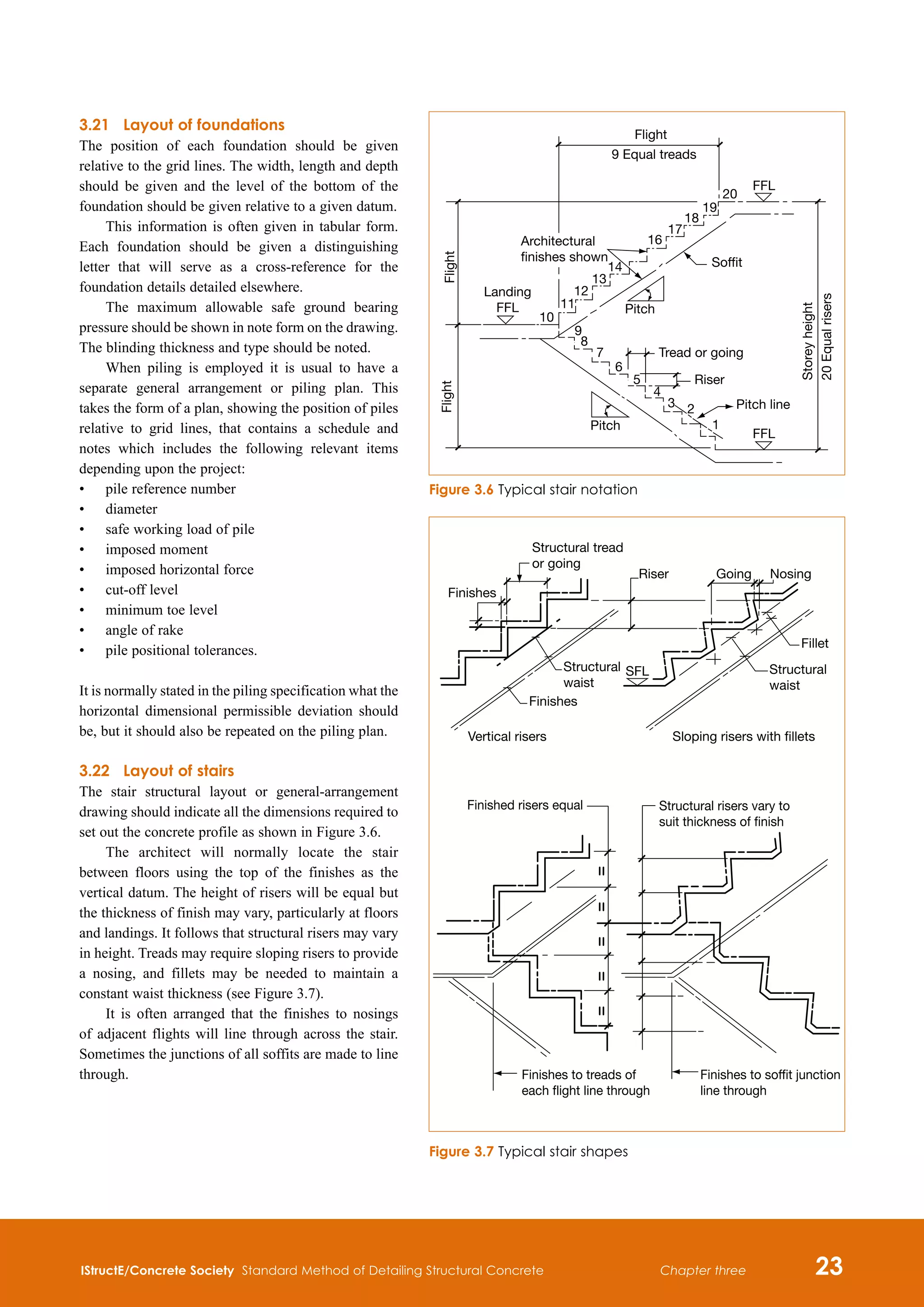
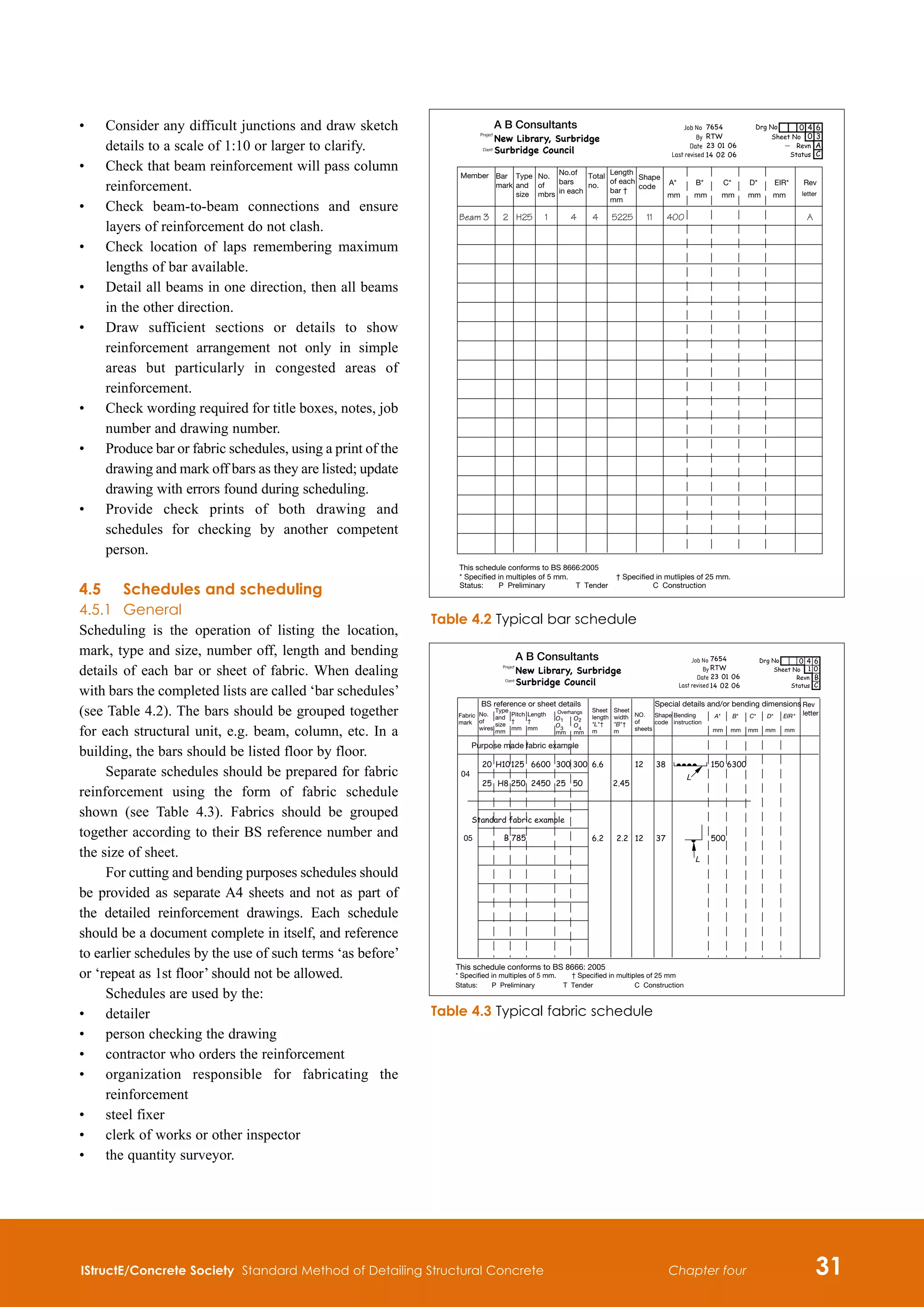
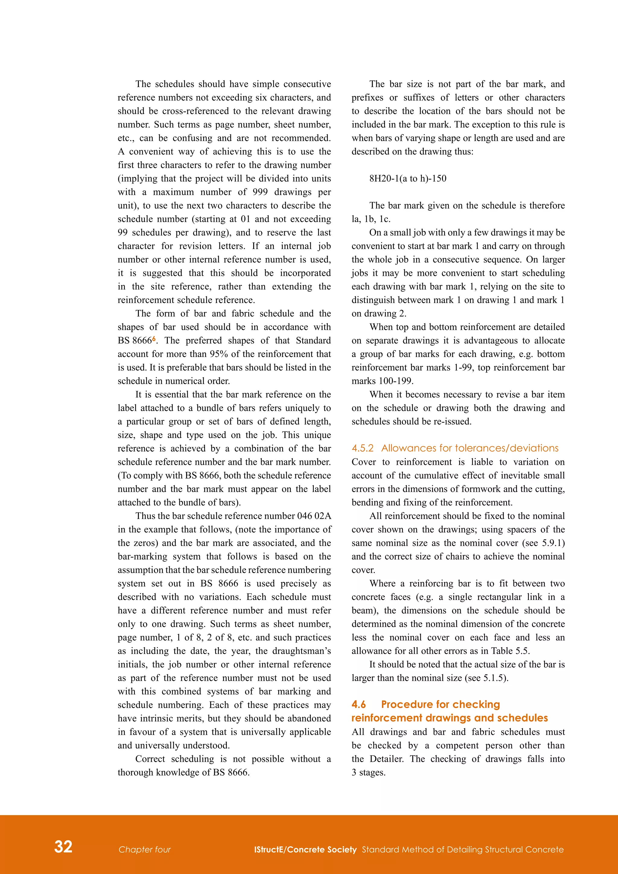
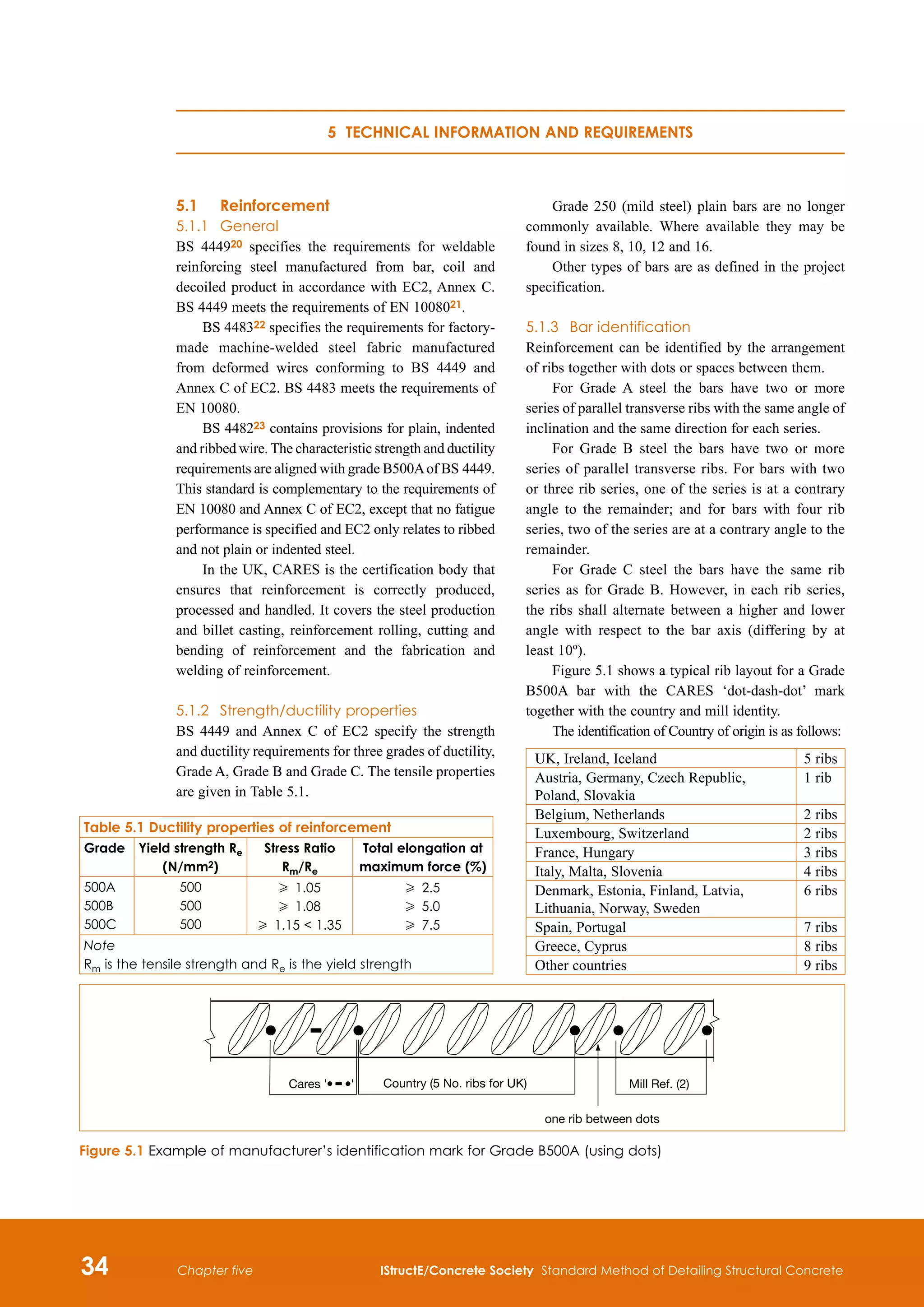
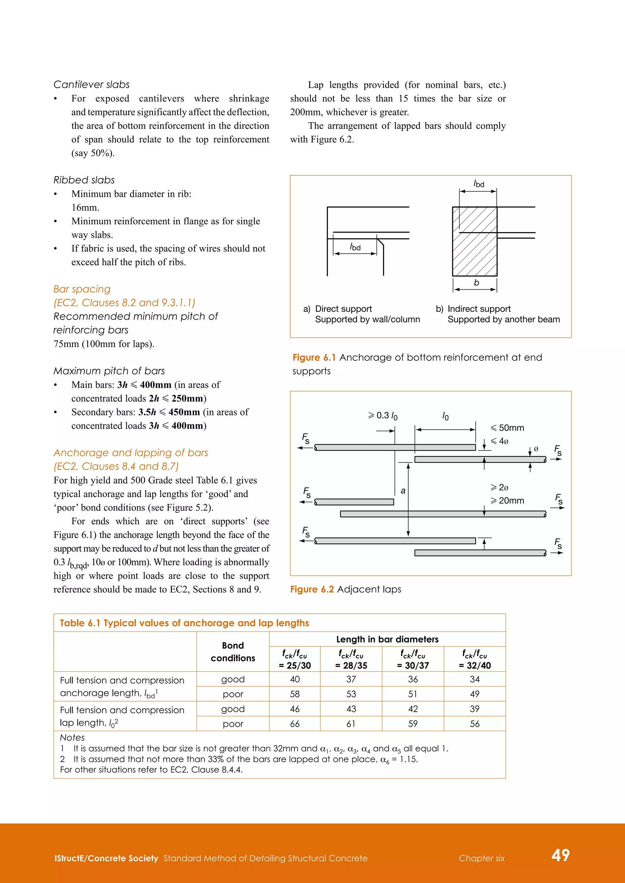
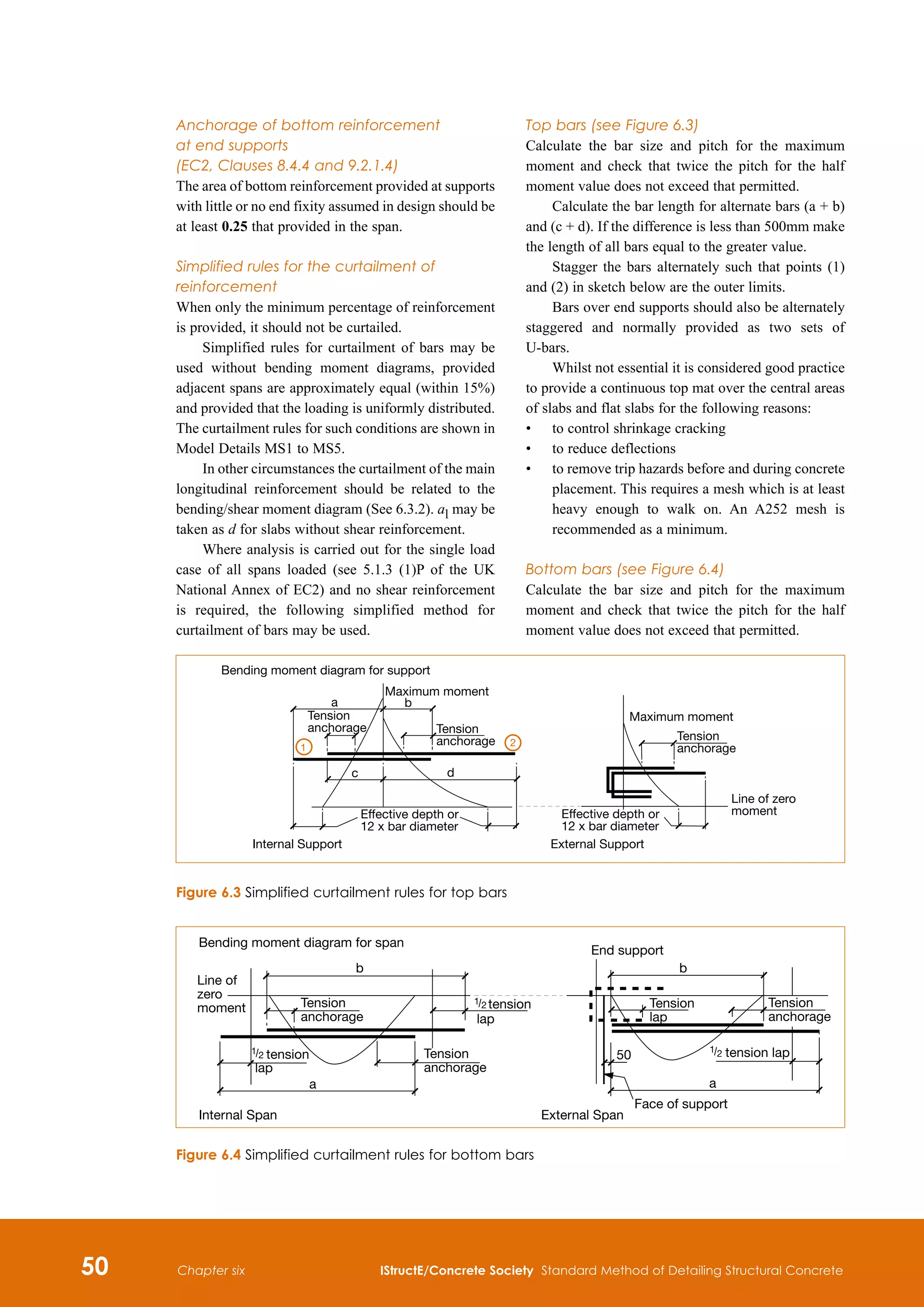
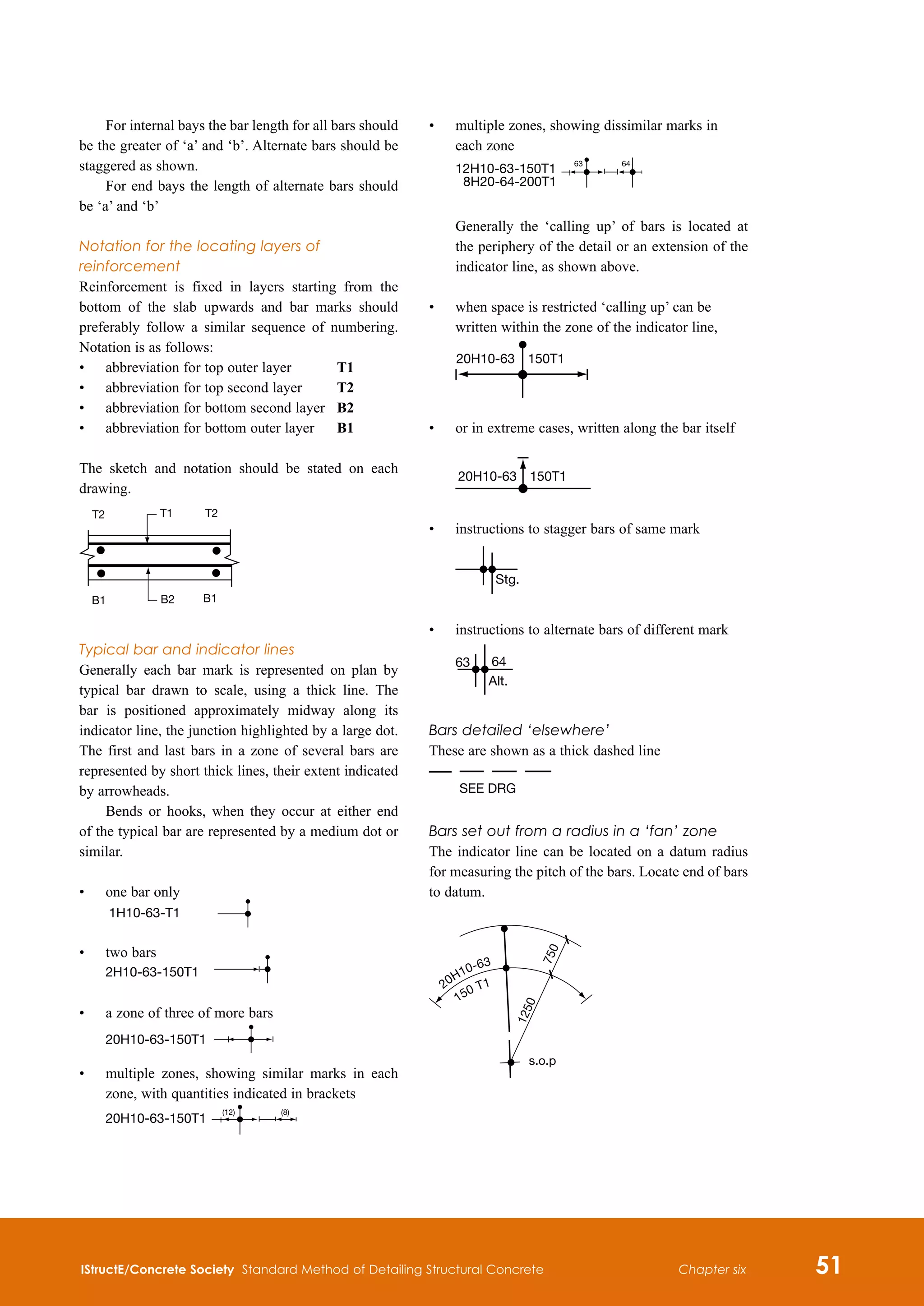
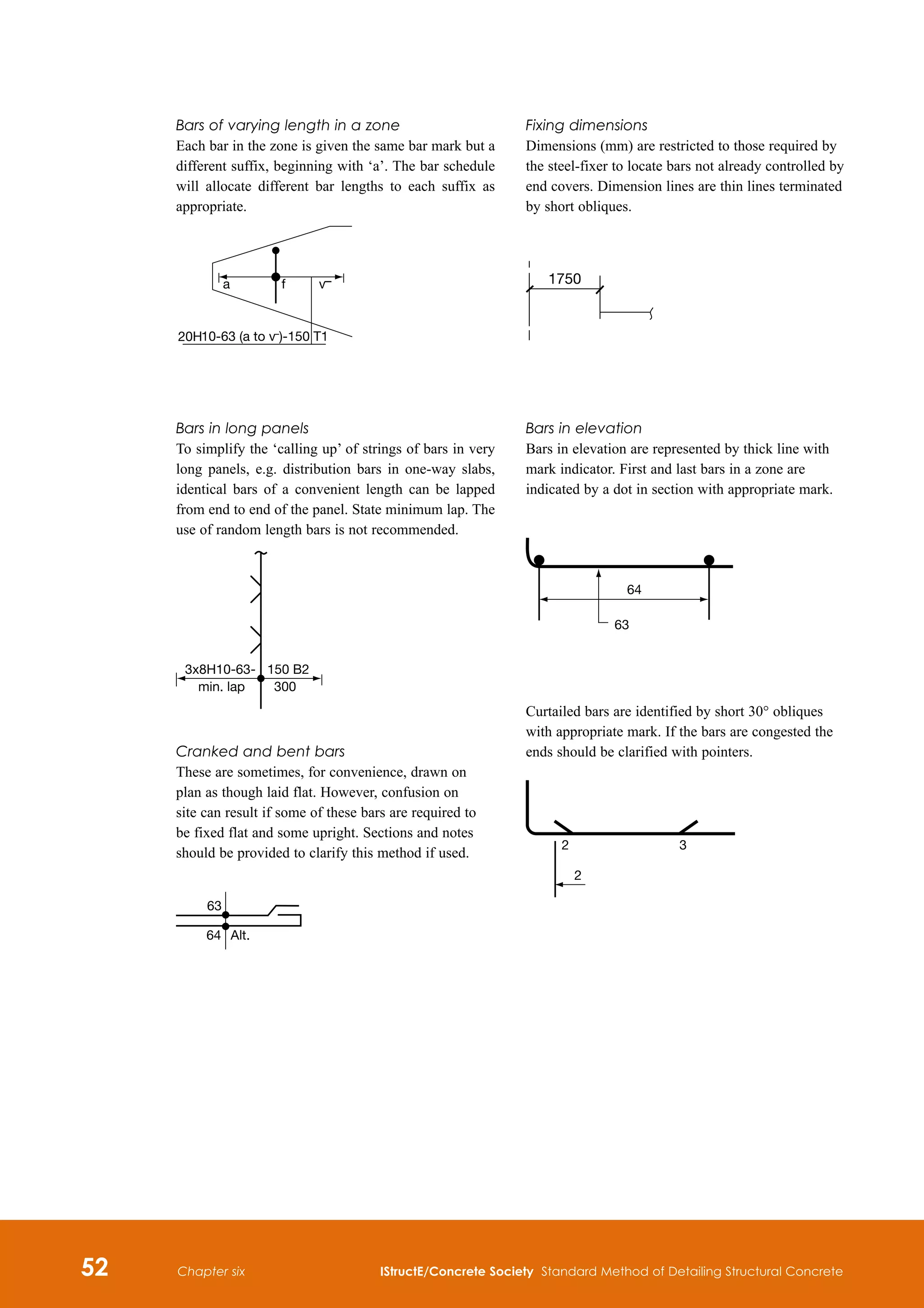
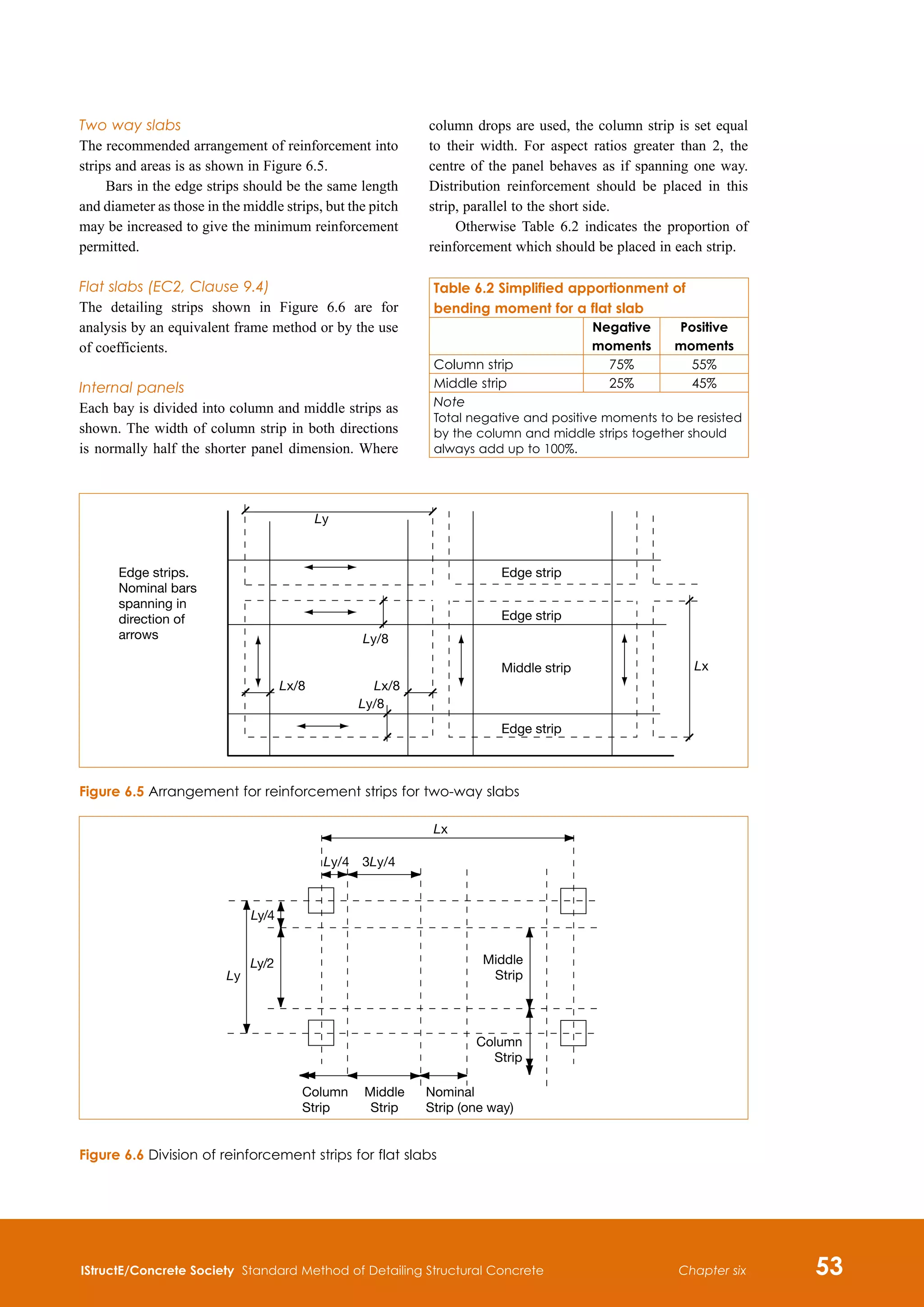
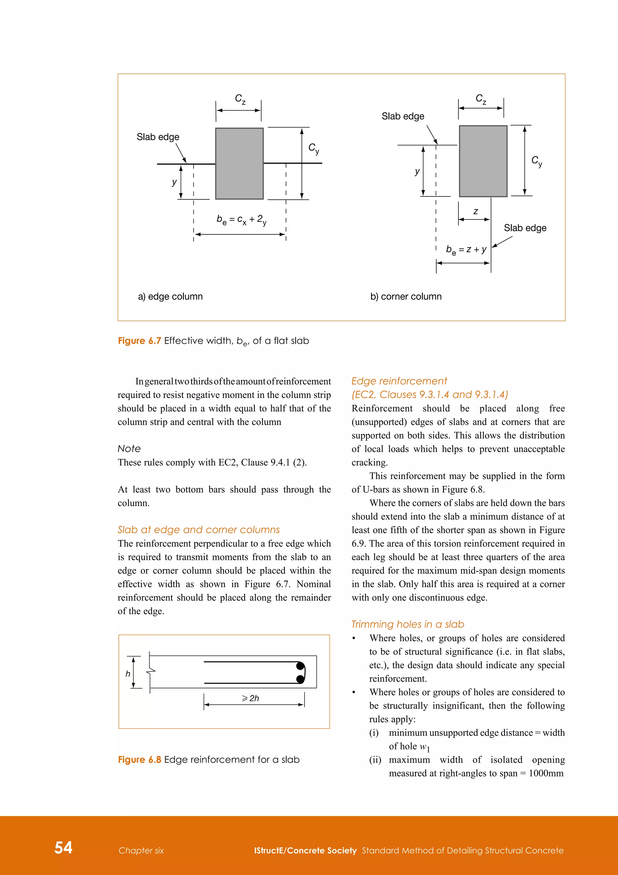
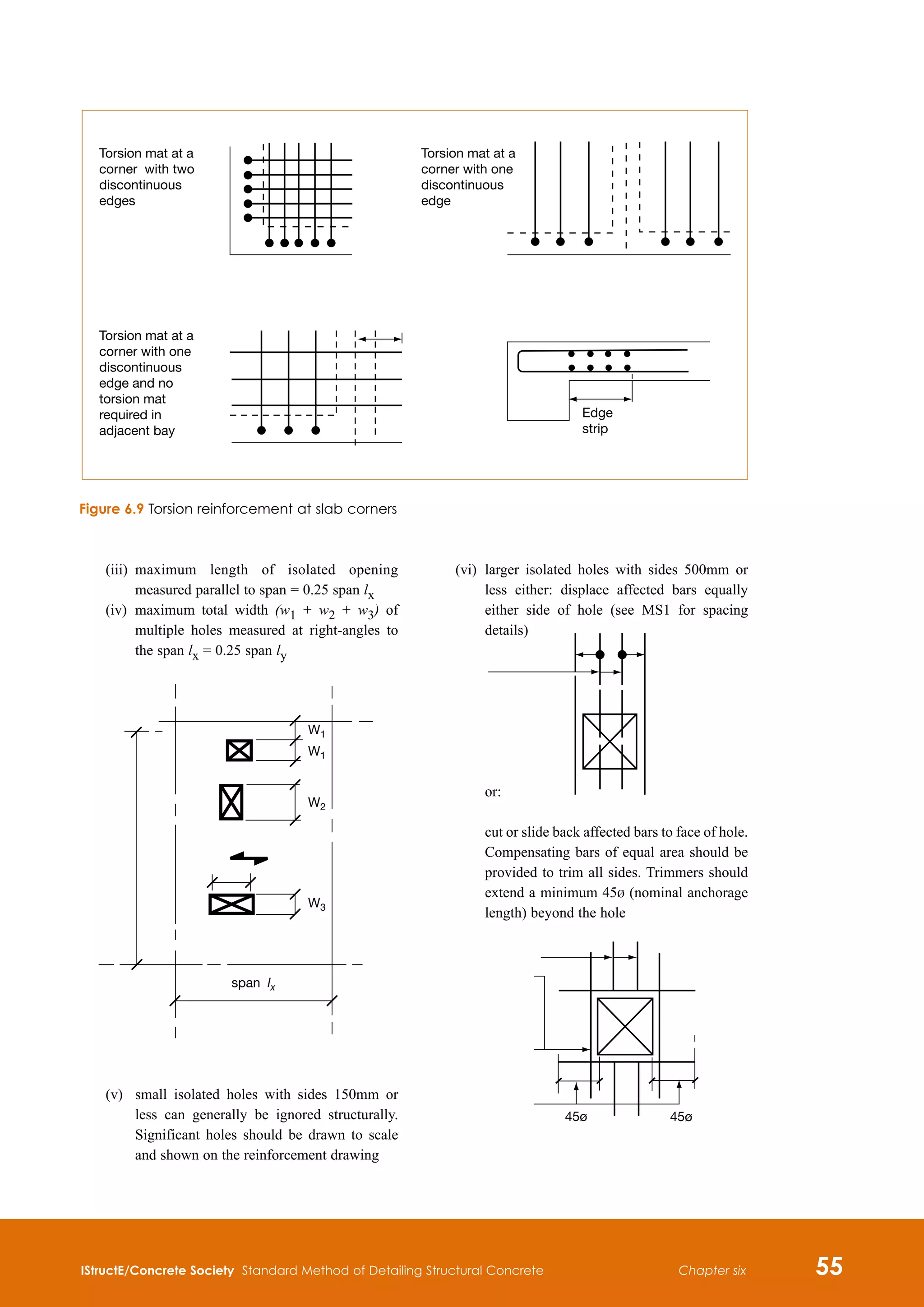
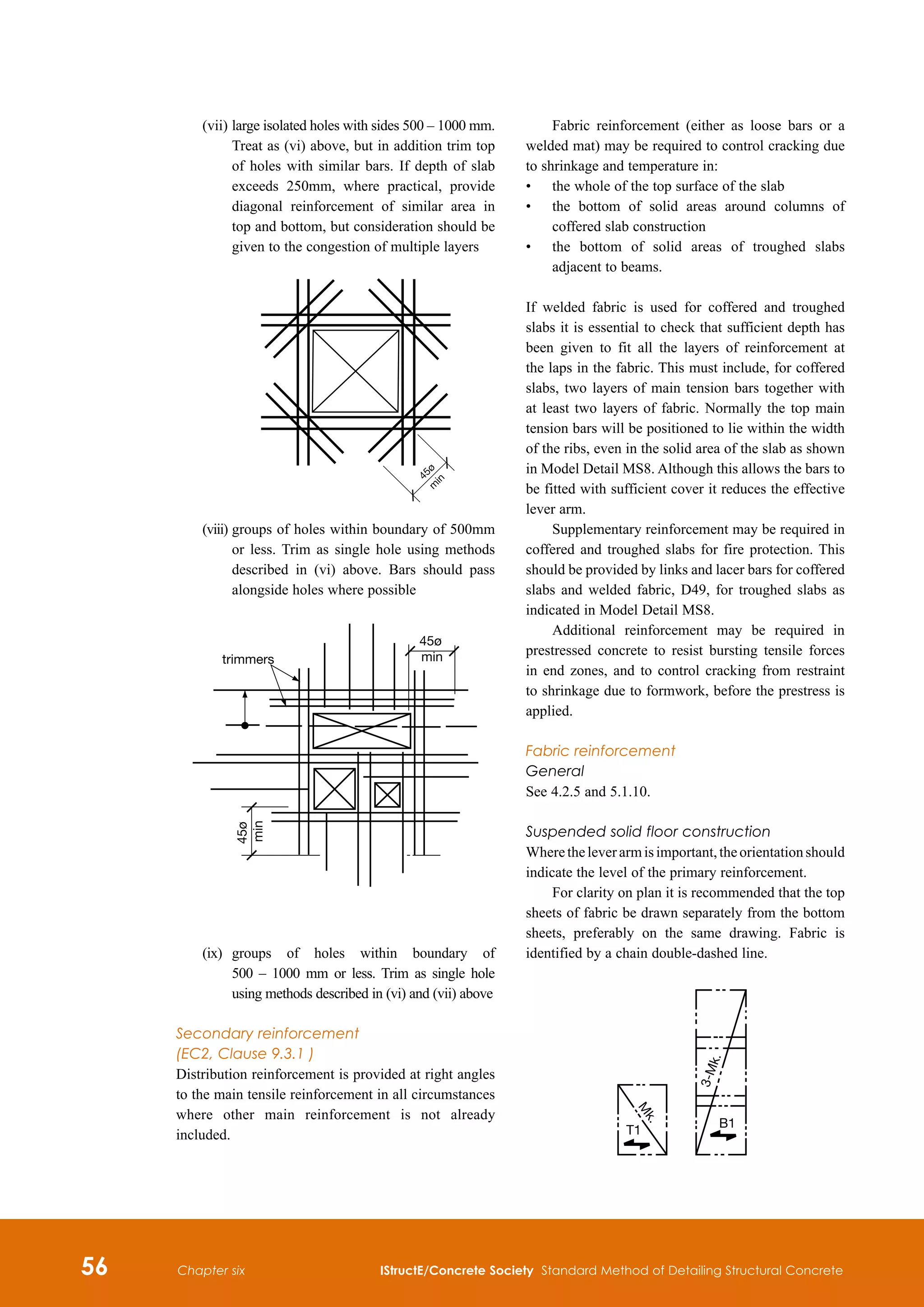
This document provides guidance on best practices for detailing structural concrete. It aims to be a standard reference used alongside design codes and manuals. The third edition considers the effects of Eurocode 2 on detailing principles and materials. It provides guidance consistent with Eurocodes based on input from industry members and consultants. The manual reflects current concerns and developments in structural concrete detailing.


(F1) H Ft kN/m
where (gk + qk) is the sum of the average permanent
and variable floor loads (in kN/m2), lr is the greater
of the distances (in m) between the centres of the
columns, frames or walls supporting any two
adjacent floor spans in the direction of the tie under
consideration and Ft = (20 + 4no) G 60kN/m. The
maximum spacing of internal ties = 1.5 lr .
Horizontal ties to columns and/or walls
Edge columns and walls should be tied horizontally
to the structure at each floor and roof level. Such ties
should be capable of resisting a design tensile force
which is the greater of 2 Ft G ls /2.5 Ft, where ls is
the floor to ceiling height in m, and 3% of the total
design ultimate vertical load carried by the column
or wall at that level. The force is in kN per metre
run of wall and in kN per column.
Tying of external walls is only required if the
peripheral tie is not located within the wall.
Corner columns should be tied in two directions.
Steel provided for the peripheral tie may be used as
the horizontal tie in this case.
All precast floor, roof and stair members should
be effectively anchored whether or not such members
are used to provide other ties. Such anchorages should
be capable of carrying the dead weight of the member
to that part of the structure that contains the ties.
Vertical ties
Each column and each wall carrying vertical load
should be tied continuously from the lowest to the
highest level. The tie should be capable of carrying
a tensile force equal to the design load likely to
be received by the column or wall from any one
storey under accidental design situation (i.e. loading
calculated using Expression 6.11b of BS EN 1990).
Continuity and anchorage of ties
Ties in two horizontal directions shall be effectively
continuous and anchored at the perimeter of the
structure. They may be provided wholly within the
in-situ concrete topping or at connections of precast
members. Where ties are not continuous in one plane,
the bending effects resulting from the eccentricities
should be considered.
Ties should not normally be lapped in narrow
joints between precast units. Mechanical anchorage
should be used in these cases.
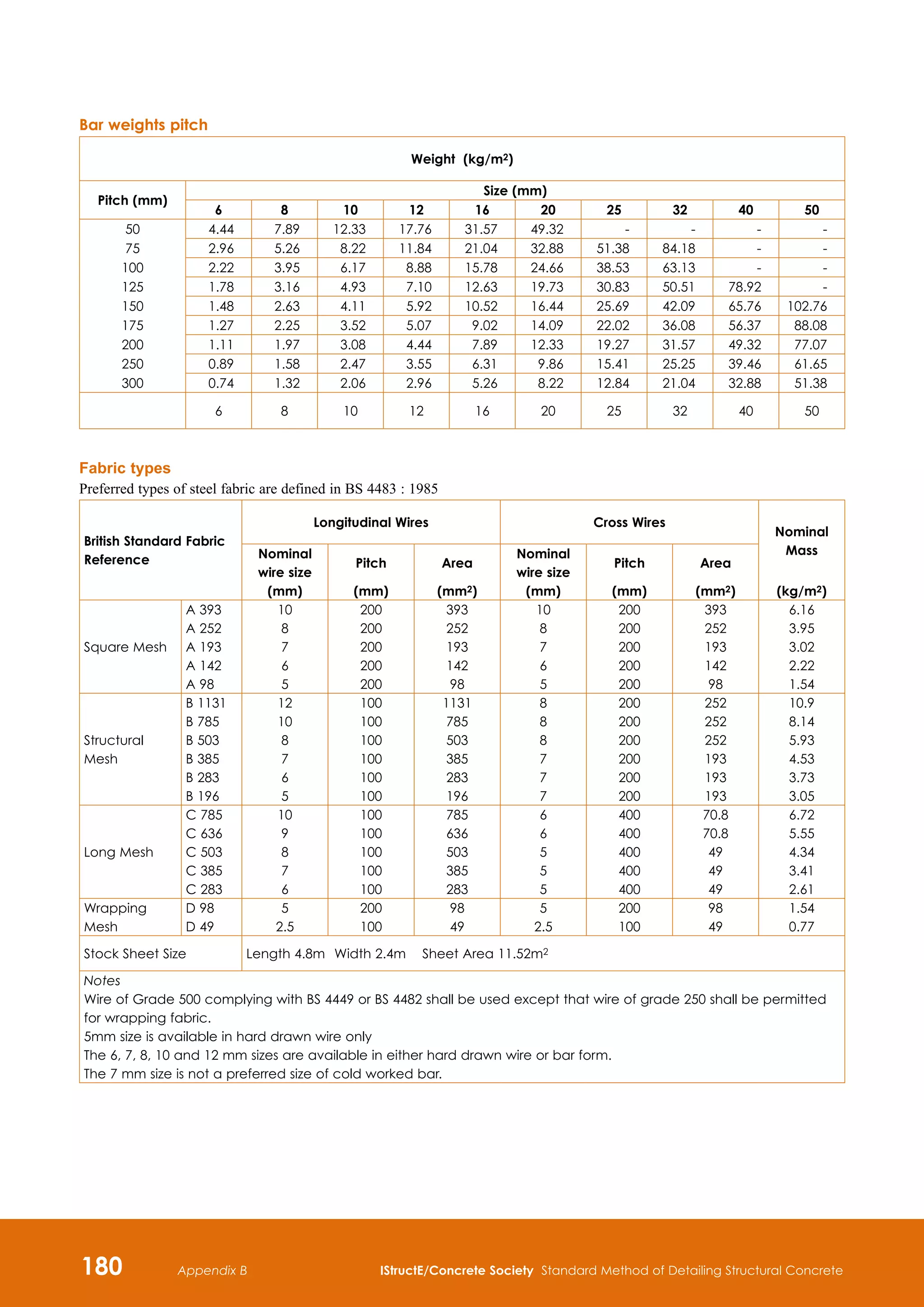
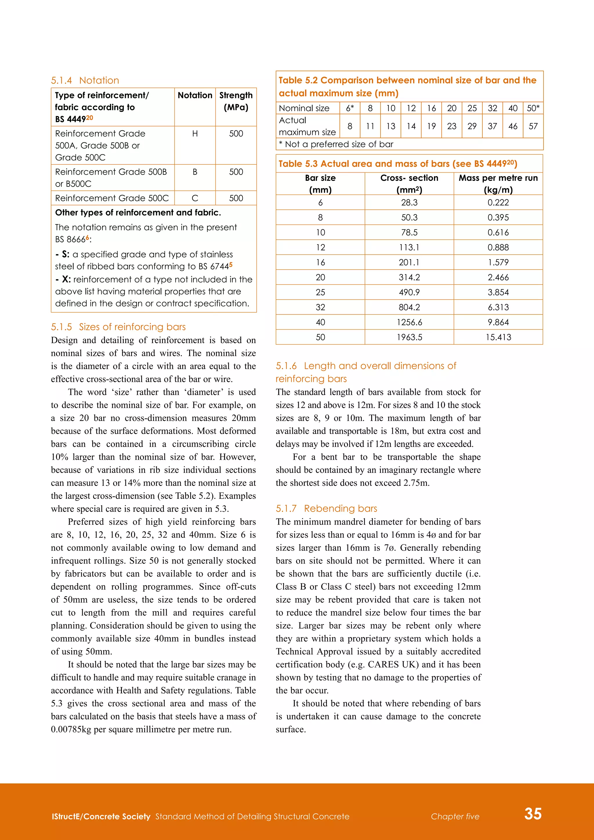
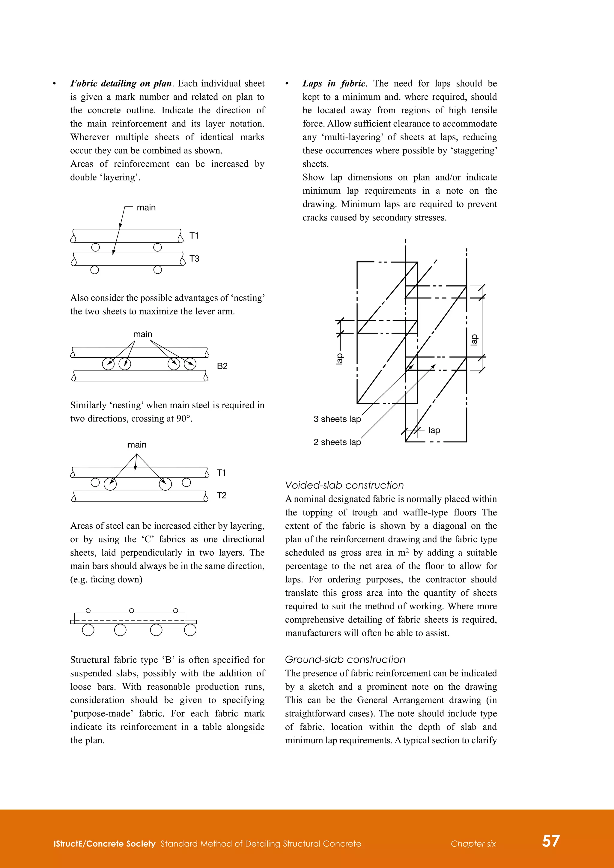
5.1.10 Fabric reinforcement
(see also 4.2.5 and 6.2.2)
There are three classifications of fabric
reinforcement:
•
Designated or Standard Fabric
•
Scheduled or Non-Standard Fabric
•
Detailed or Purpose Made Fabric
For detailing and scheduling of fabric see Section 4.
For British Standard fabrics see Tables at the end of
this manual.](https://image.slidesharecdn.com/detailingstandardmethod3rded2006istructe-211001083748/75/Detailing-standard-method-3rd-ed-2006-istruct-e-49-2048.jpg)
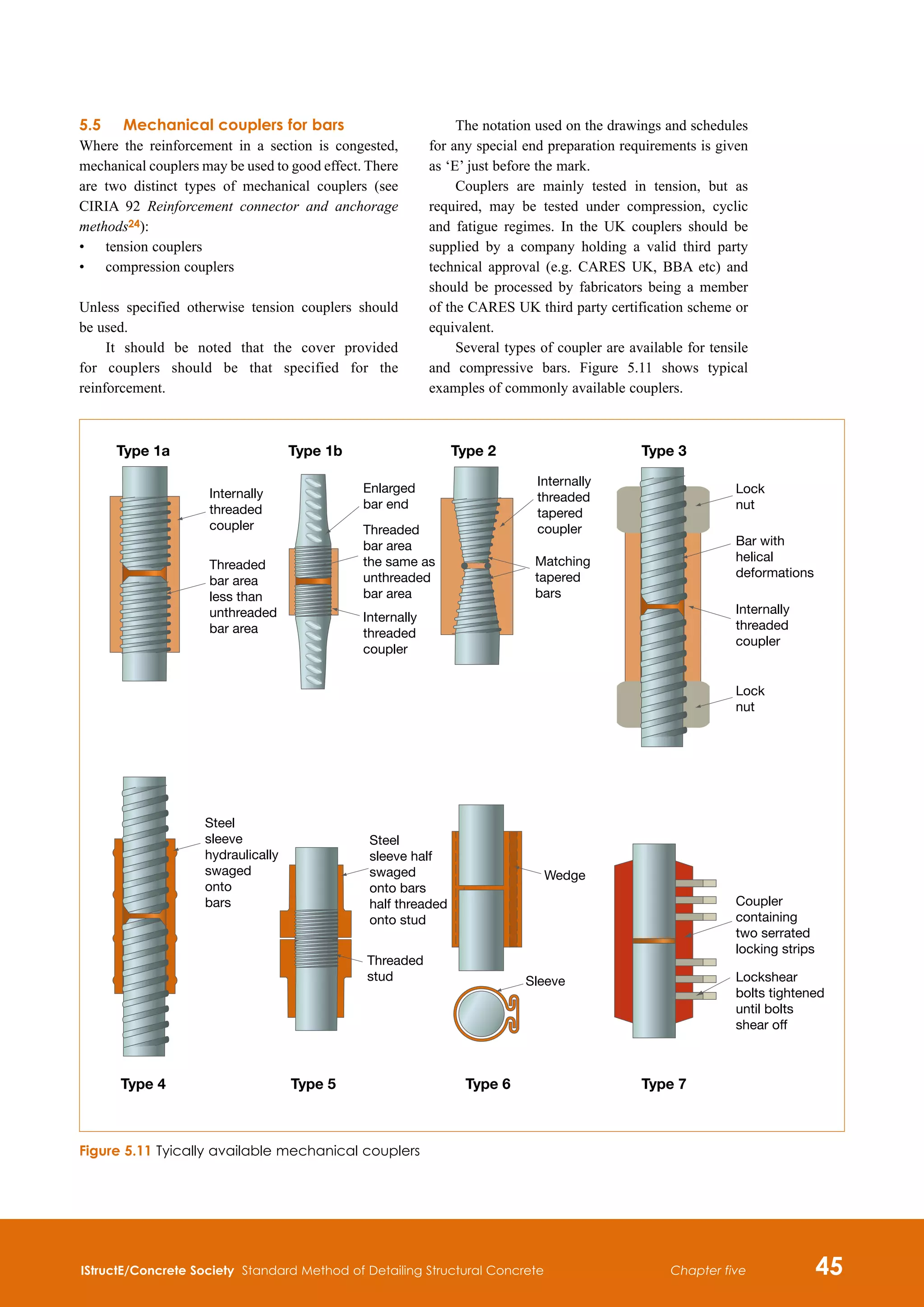
![40 IStructE/Concrete Society Standard Method of Detailing Structural Concrete
Chapter five
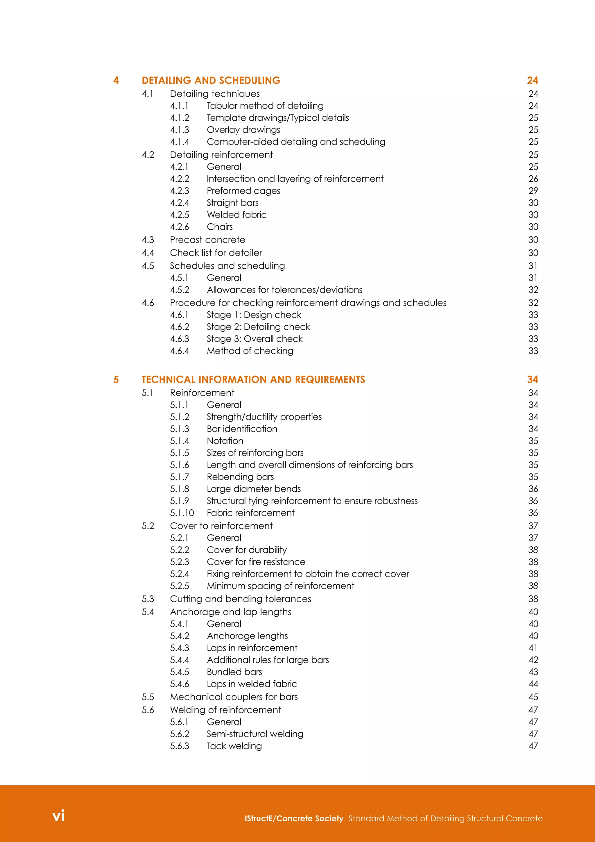
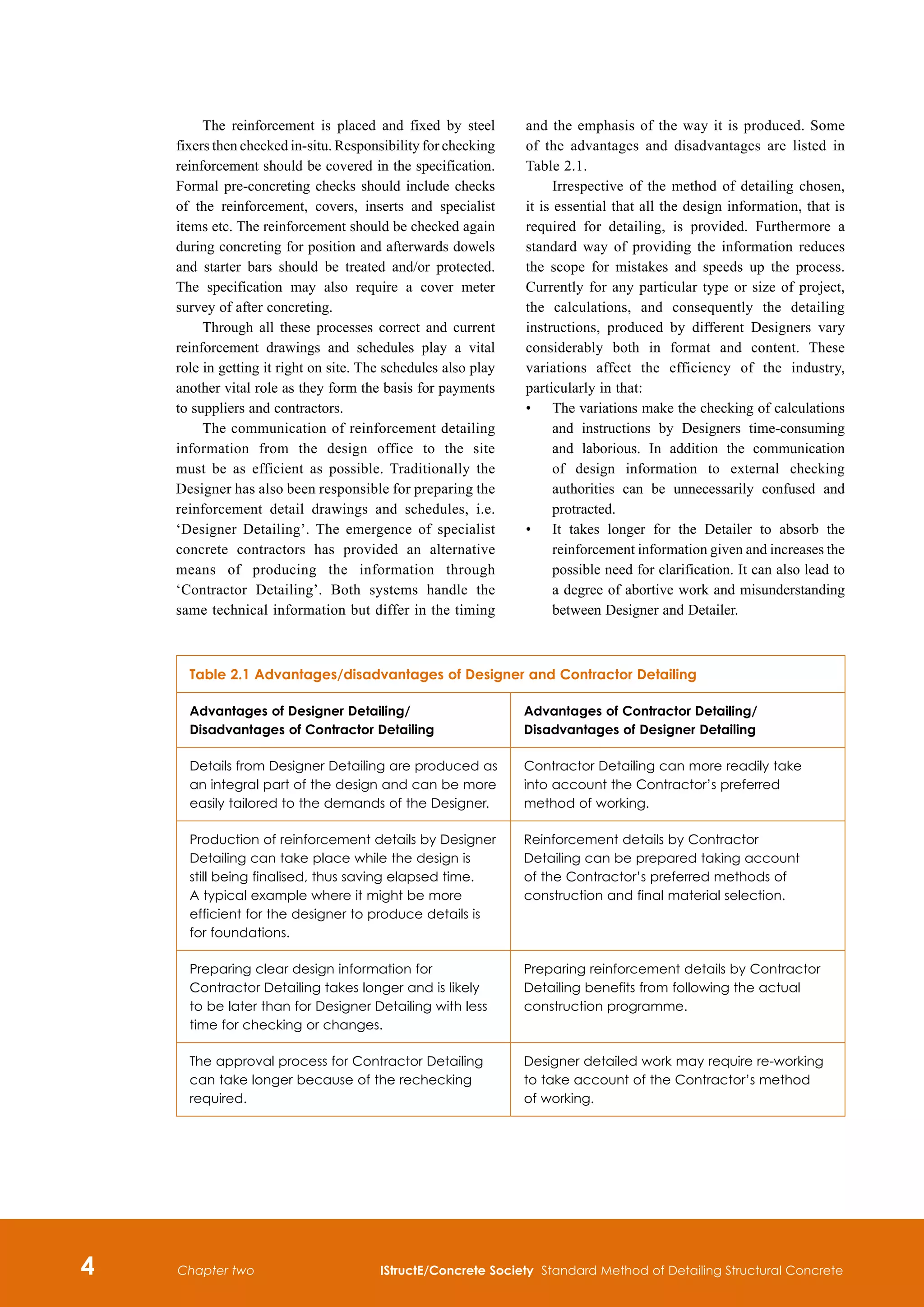
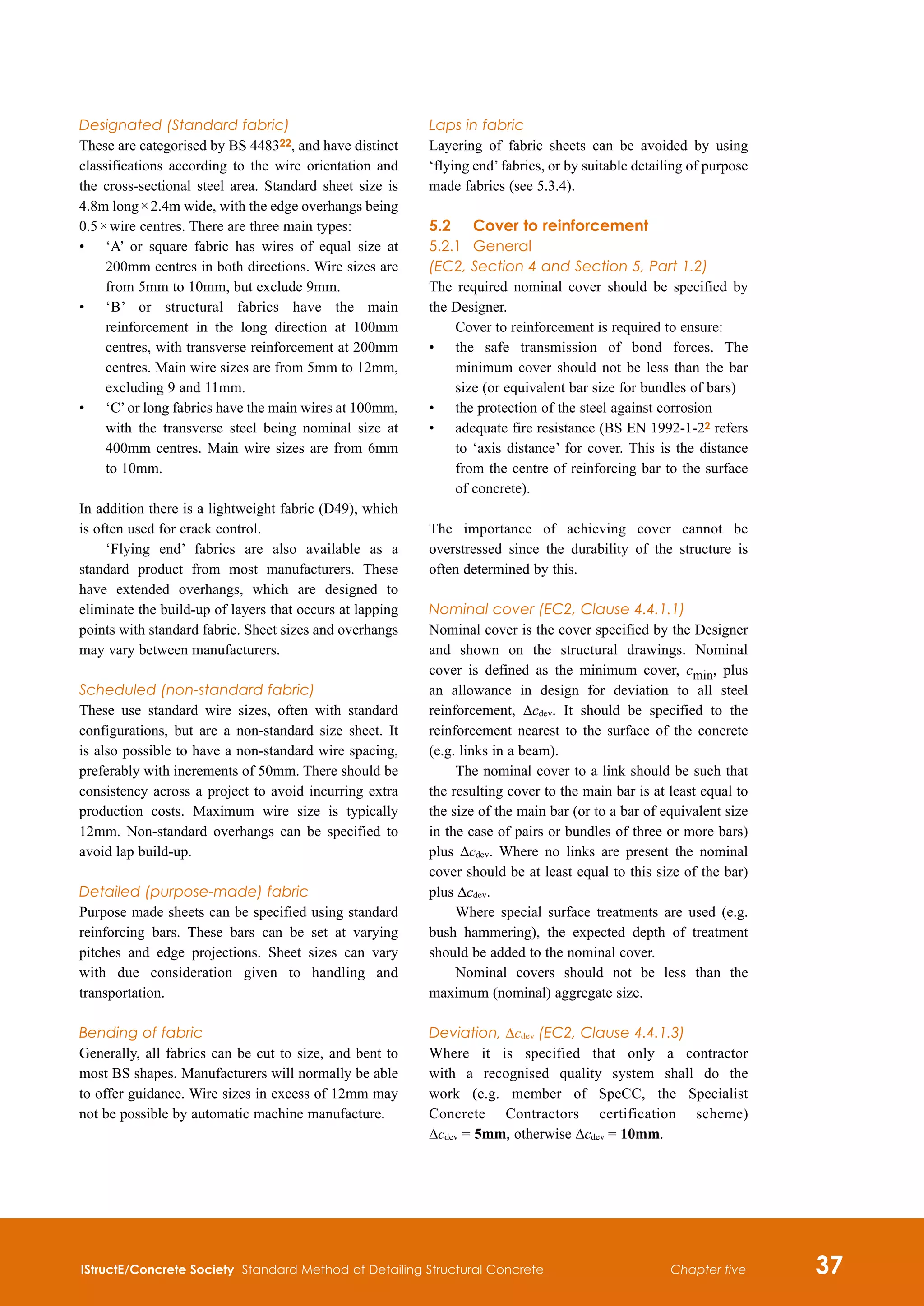
5.4 Anchorage and lap lengths
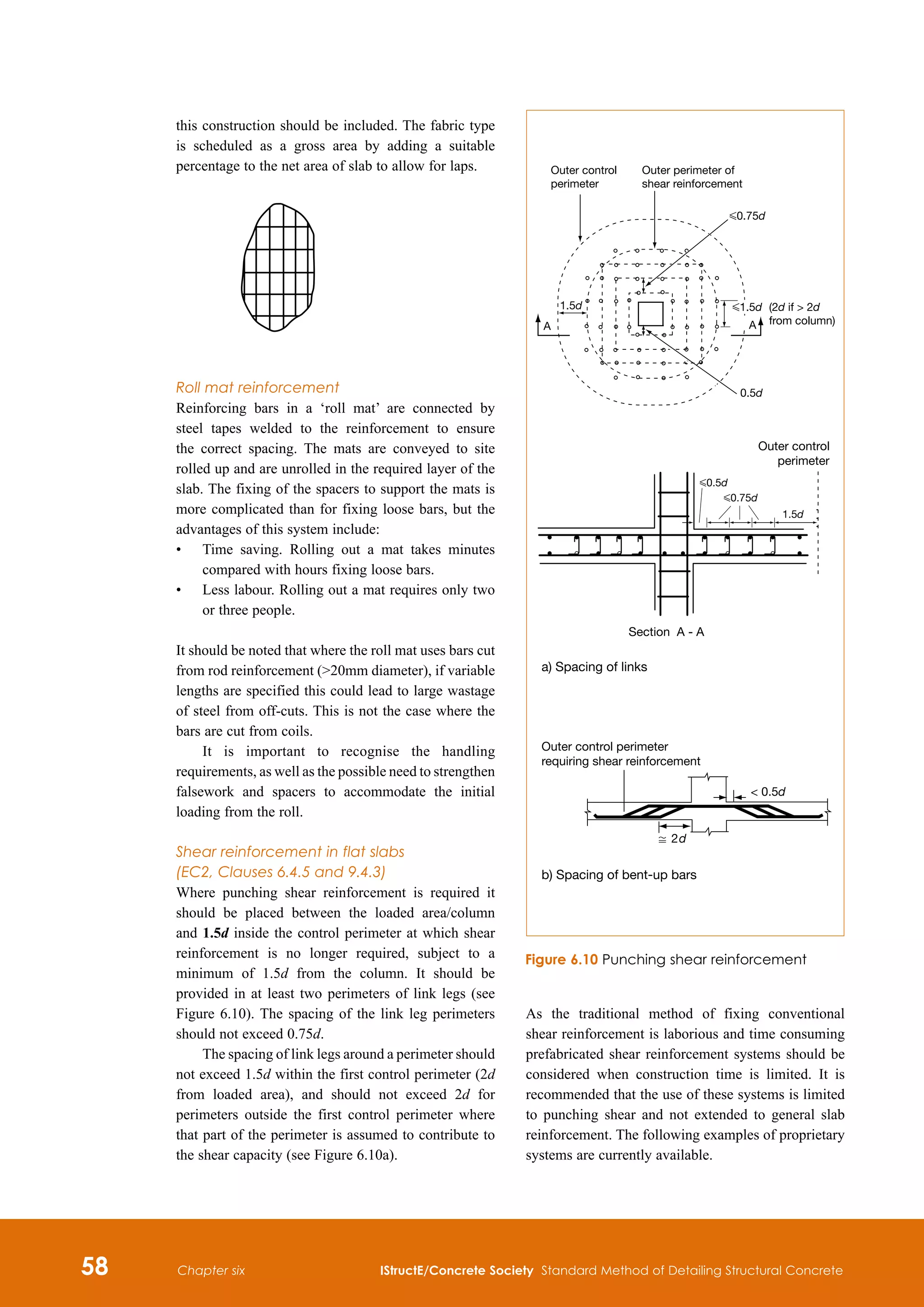
5.4.1 General (EC2, Clause 8.4)
The bond between the concrete and reinforcement
determines the anchorage and lap lengths. The
description of bond conditions for different positions
of the reinforcement in the concrete are indicated in
Figure 5.2.
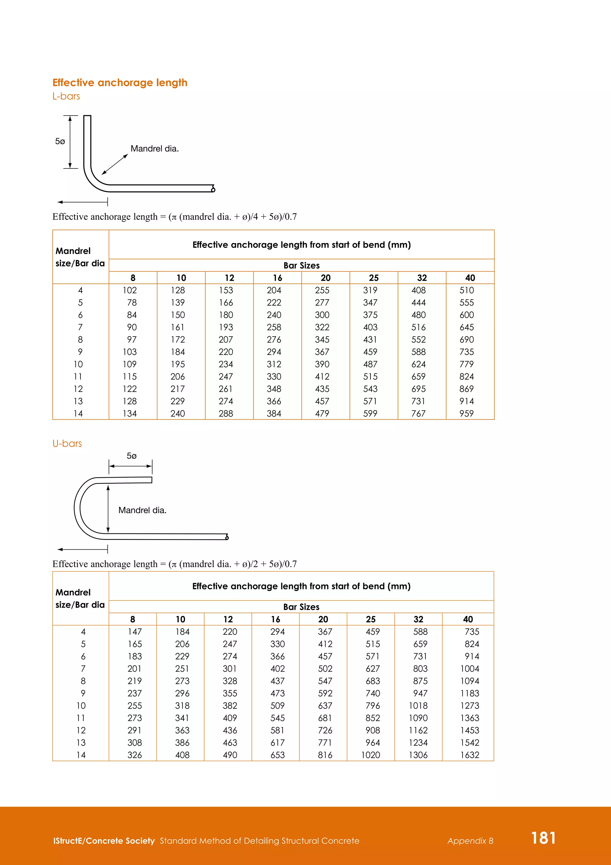
5.4.2 Anchorage lengths
Anchorage lengths, lap lengths and dimensions of
shear reinforcement should be determined by the
Detailer unless noted otherwise.
The design anchorage length, lbd, is:
lbd = α1 α2 α3 α4 α5 lb, rqd H lb,min
The coefficients α1, α2, α3, α4 and α5 are given
in Table 5.6.
Table 5.6 Values of coefficients (α1, α2, α3, α4 and α5)
Influencing factor
Type of
anchorage
Reinforcement bar
In tension In compression
Shape of bars
Straight α1 = 1.0 α1 = 1.0
Other than
straight
α1 = 0.7 if cd 3b
otherwise α1 = 1.0
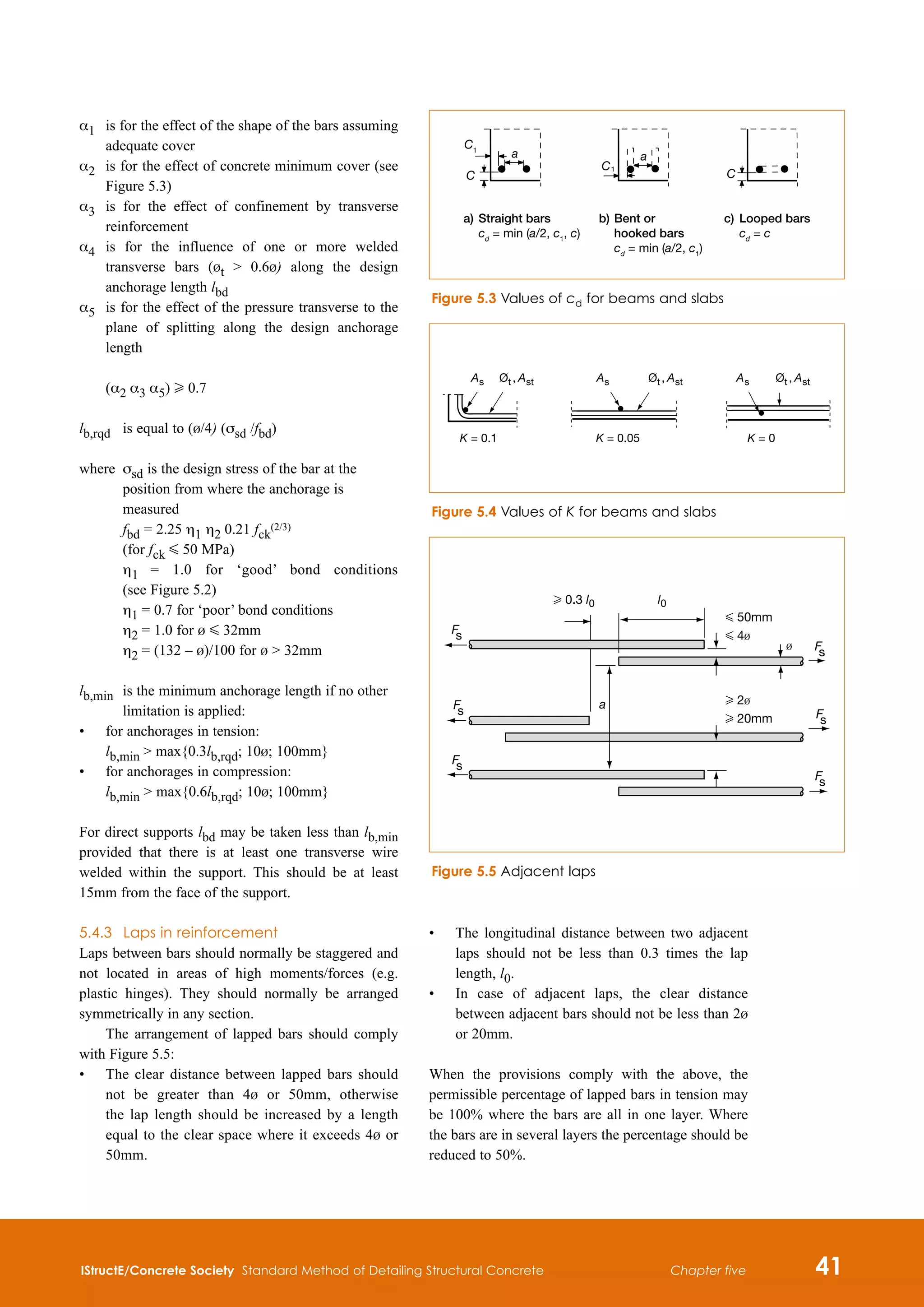
(see Figure 5.3 for values of cd)
α1 = 1.0
Concrete cover
Straight
α2 = 1 – 0.15 (cd – b)/b
H 0.7
G 1.0
α2 = 1.0
Other than
straight
α2 = 1 – 0.15 (cd – 3b)/b
H 0.7
G 1.0
(see Figure 5.3 for values of cd)
α2 = 1.0
Confinement by transverse reinforcement
not welded to main bars
All types
α3 = 1 – Kl
H 0.7
G 1.0
α3 = 1.0
Confinement by welded transverse
reinforcement
All types, position
and size
α4 = 0.7 α4 = 0.7
Confinement by transverse pressure All types
α5 = 1 – 0.04p
H 0.7 and G 1.0
Notes
l = (ΣAst – ΣAst,min)lAs
ΣAst
cross-sectional area of the transverse reinforcement along the design anchorage length lbd
ΣAst,min cross-sectional area of the minimum transverse reinforcement = 0.25 As for beams and 0 for slabs
As area of a single anchored bar with maximum bar diameter
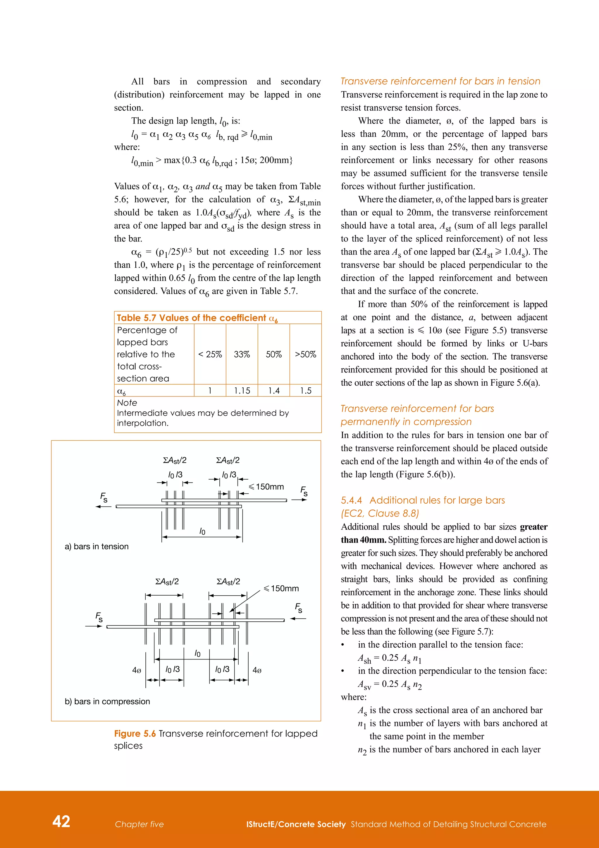
K values shown in Figure 5.4
p transverse pressure [MPa] at ultimate limit state along lbd
a) 45º G α G 90º
A
A
a) and b) 'good' bond conditions
for all bars
c) and d) unhatched zone – 'good' bond conditions
hatched zone – 'poor' bond conditions
Direction of concreting
A
300
A
h
h
250
c) h 250mm
d) h 600mm
b) h G 250mm
A
α
Figure 5.2 Description of bond conditions](https://image.slidesharecdn.com/detailingstandardmethod3rded2006istructe-211001083748/75/Detailing-standard-method-3rd-ed-2006-istruct-e-53-2048.jpg)
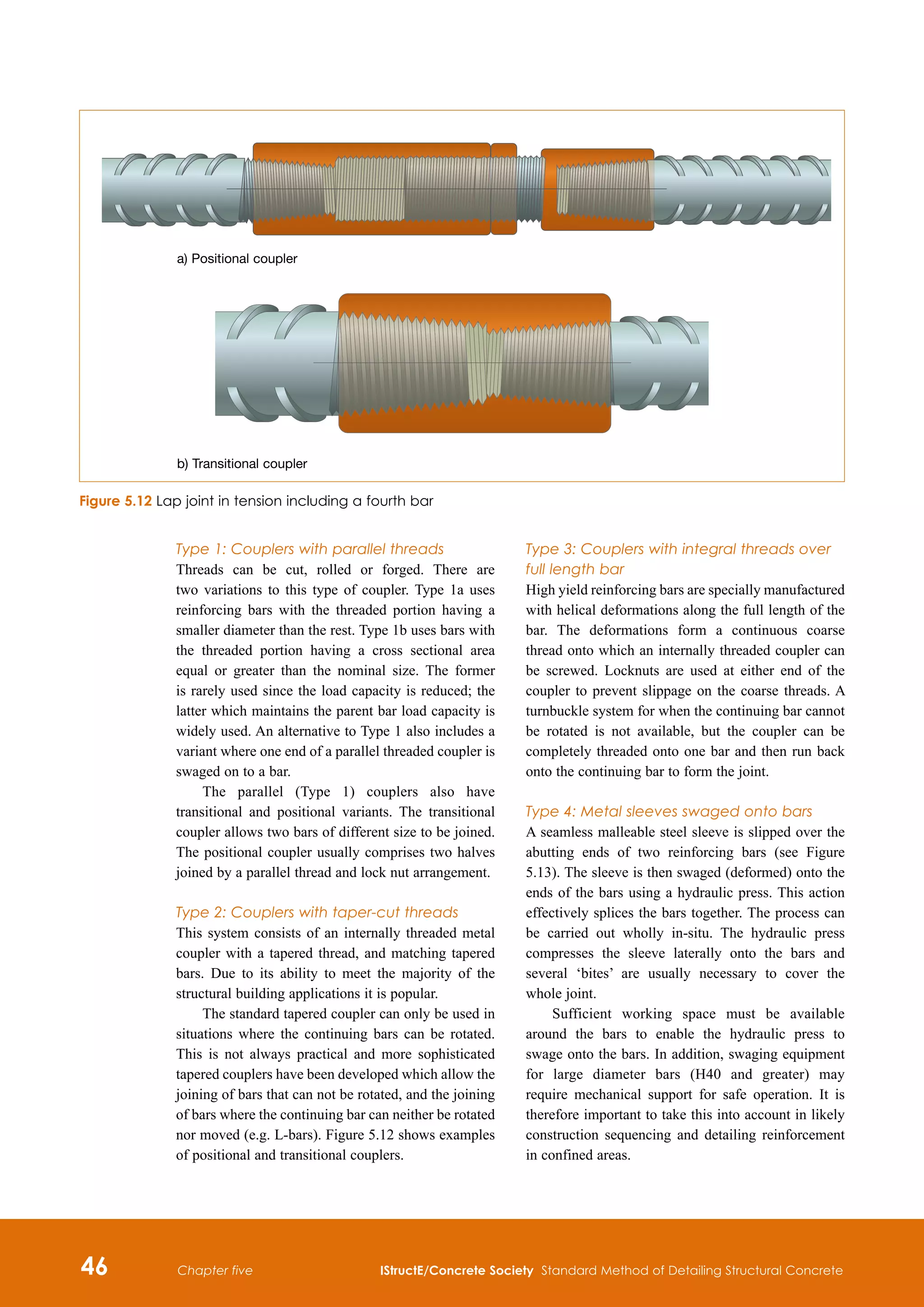
![62 IStructE/Concrete Society Standard Method of Detailing Structural Concrete
Chapter six
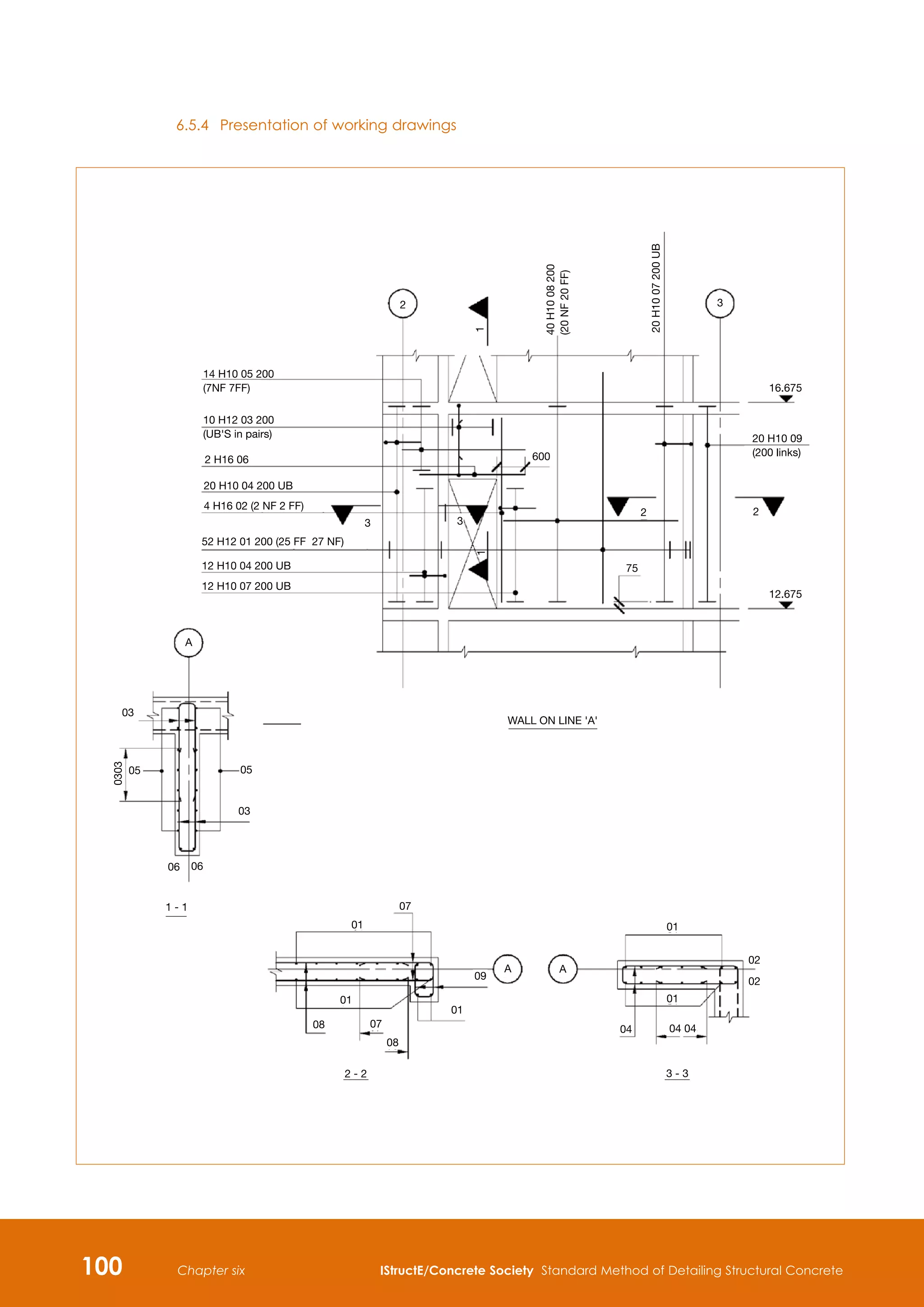
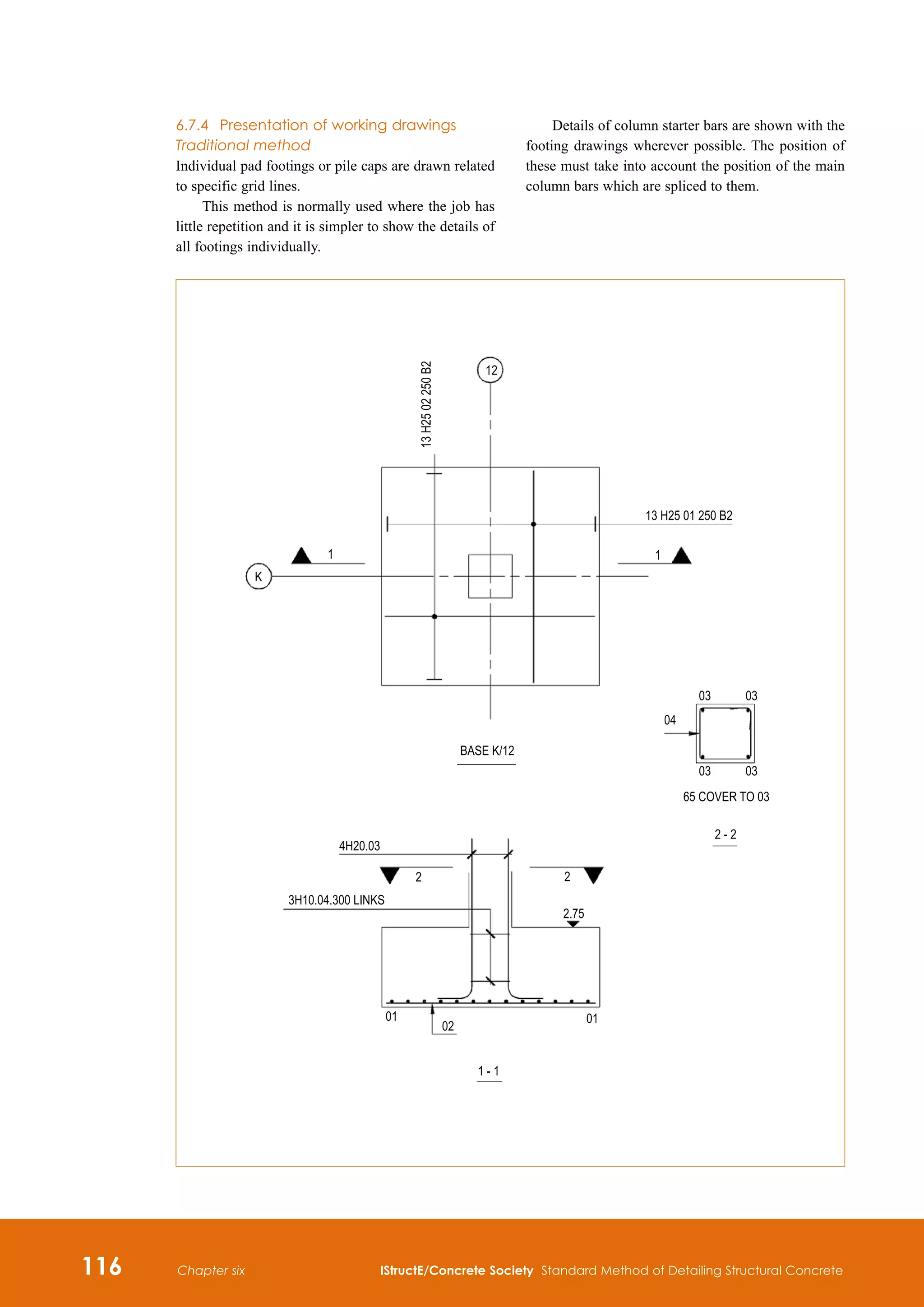
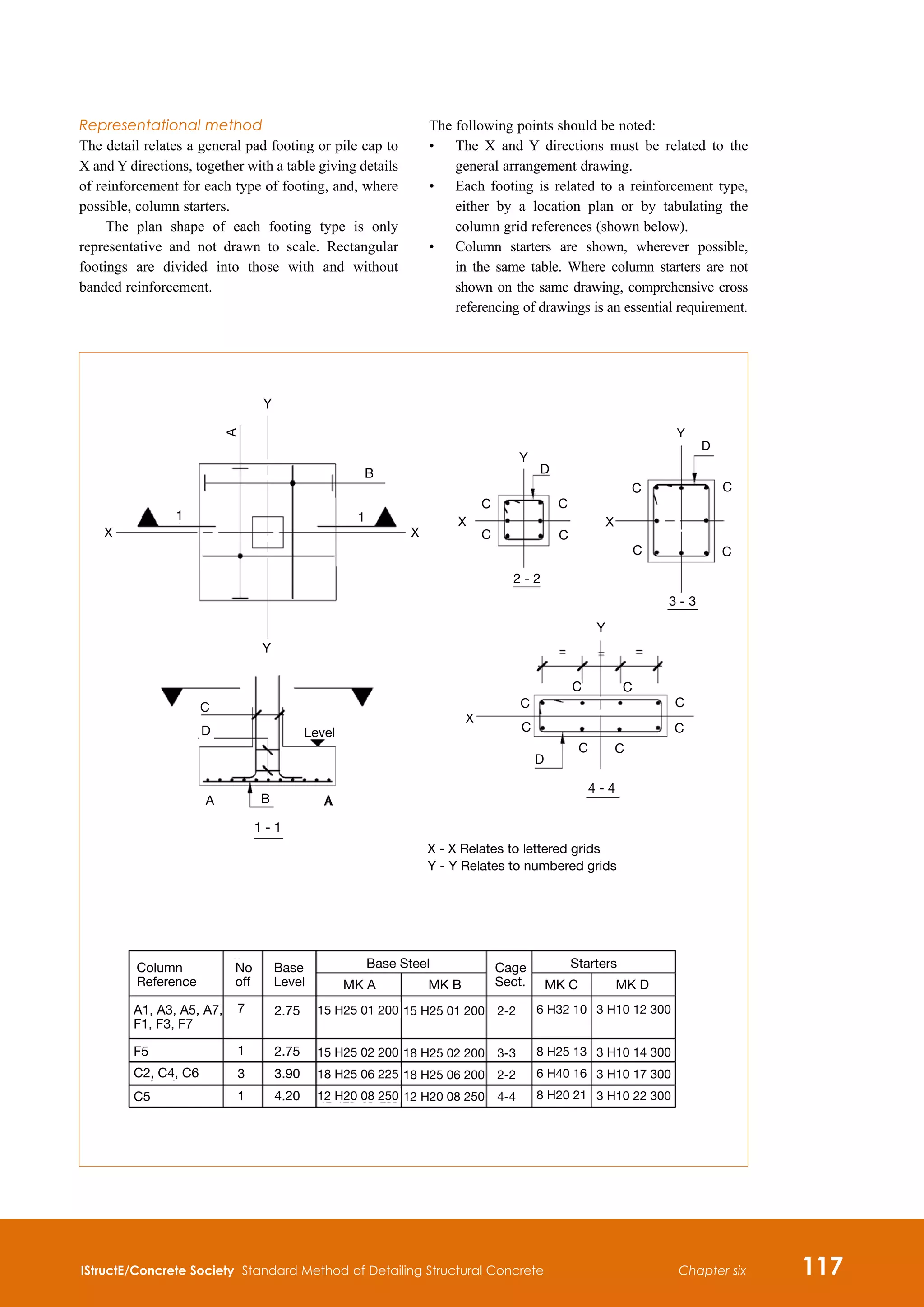
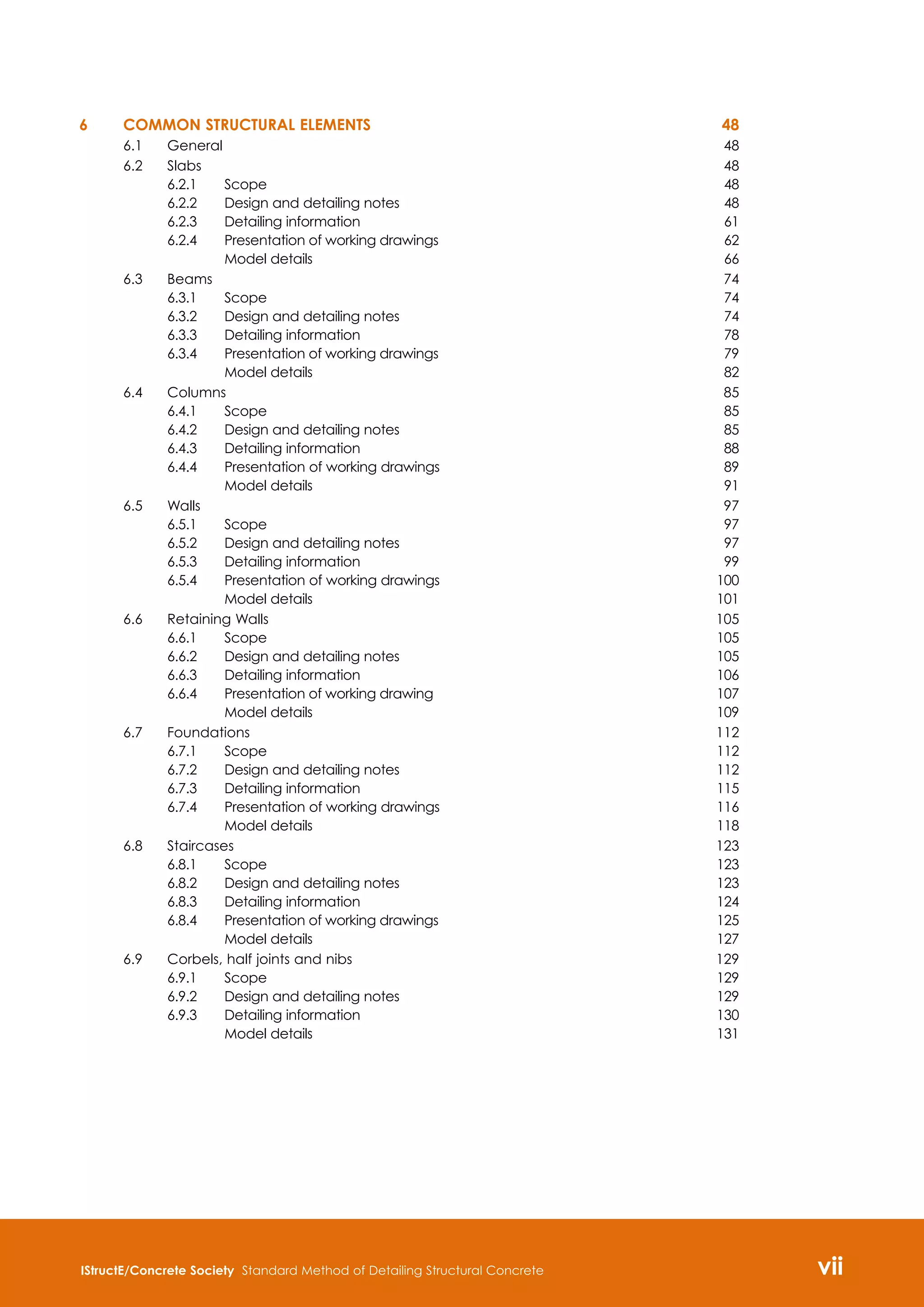
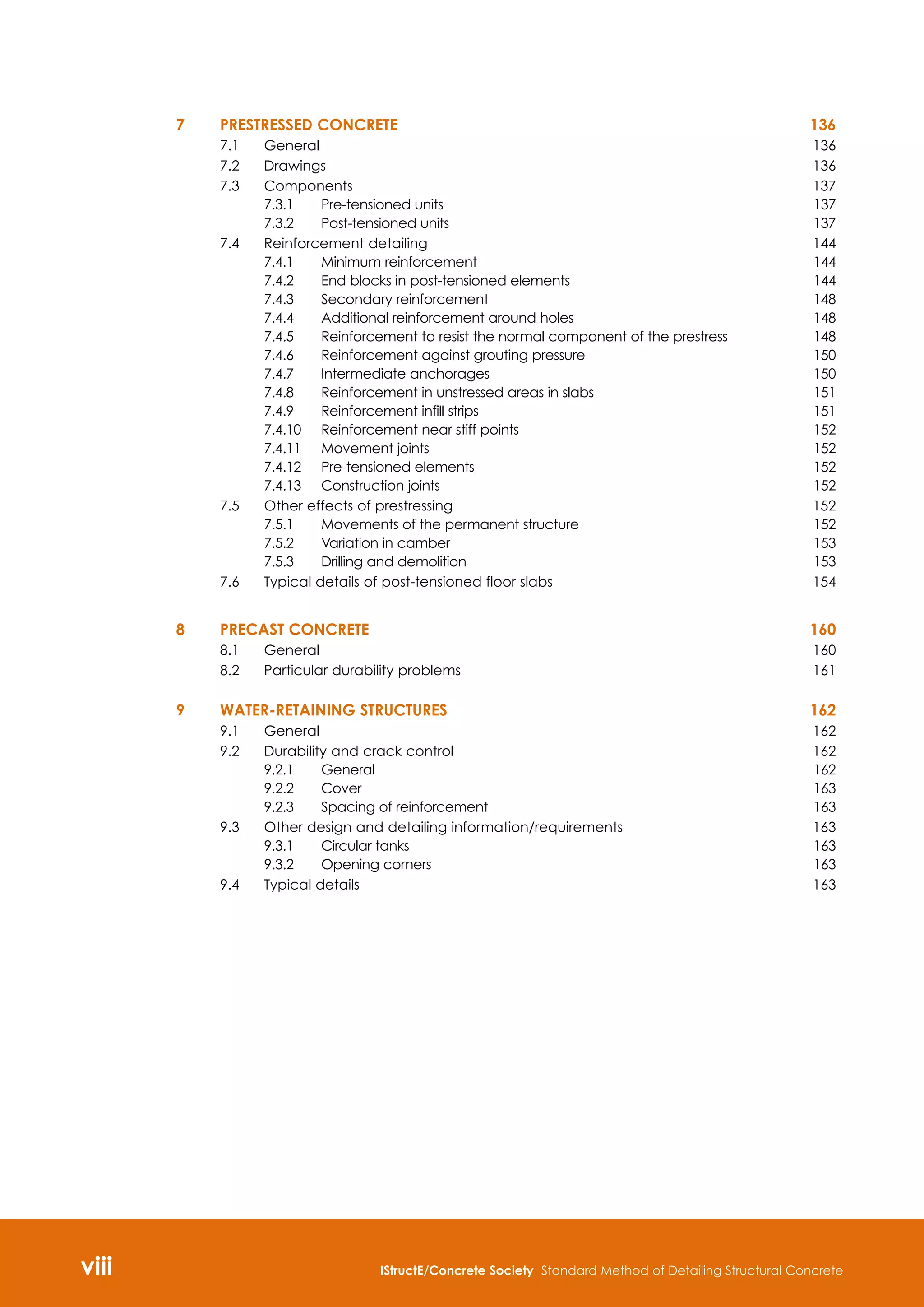
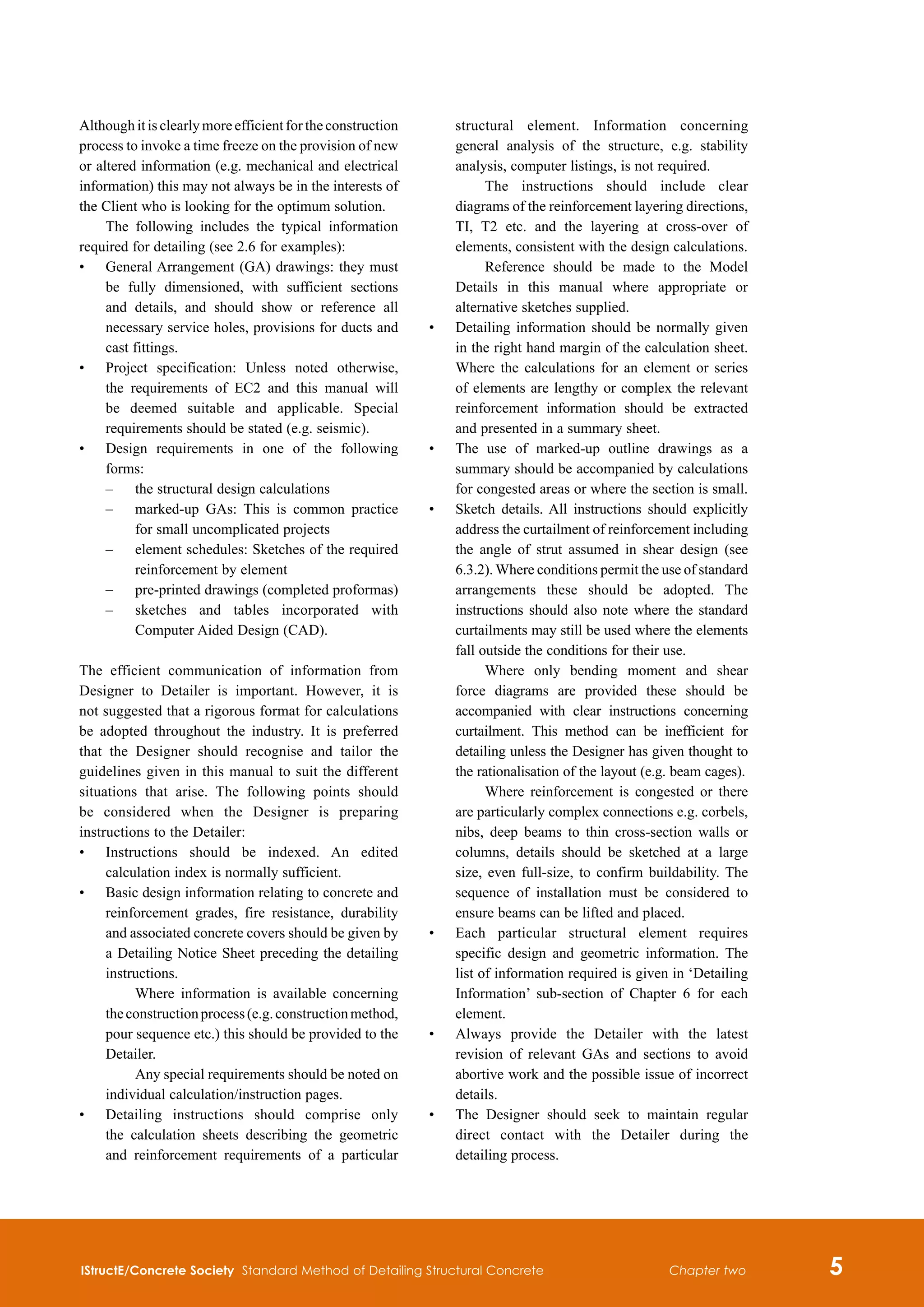
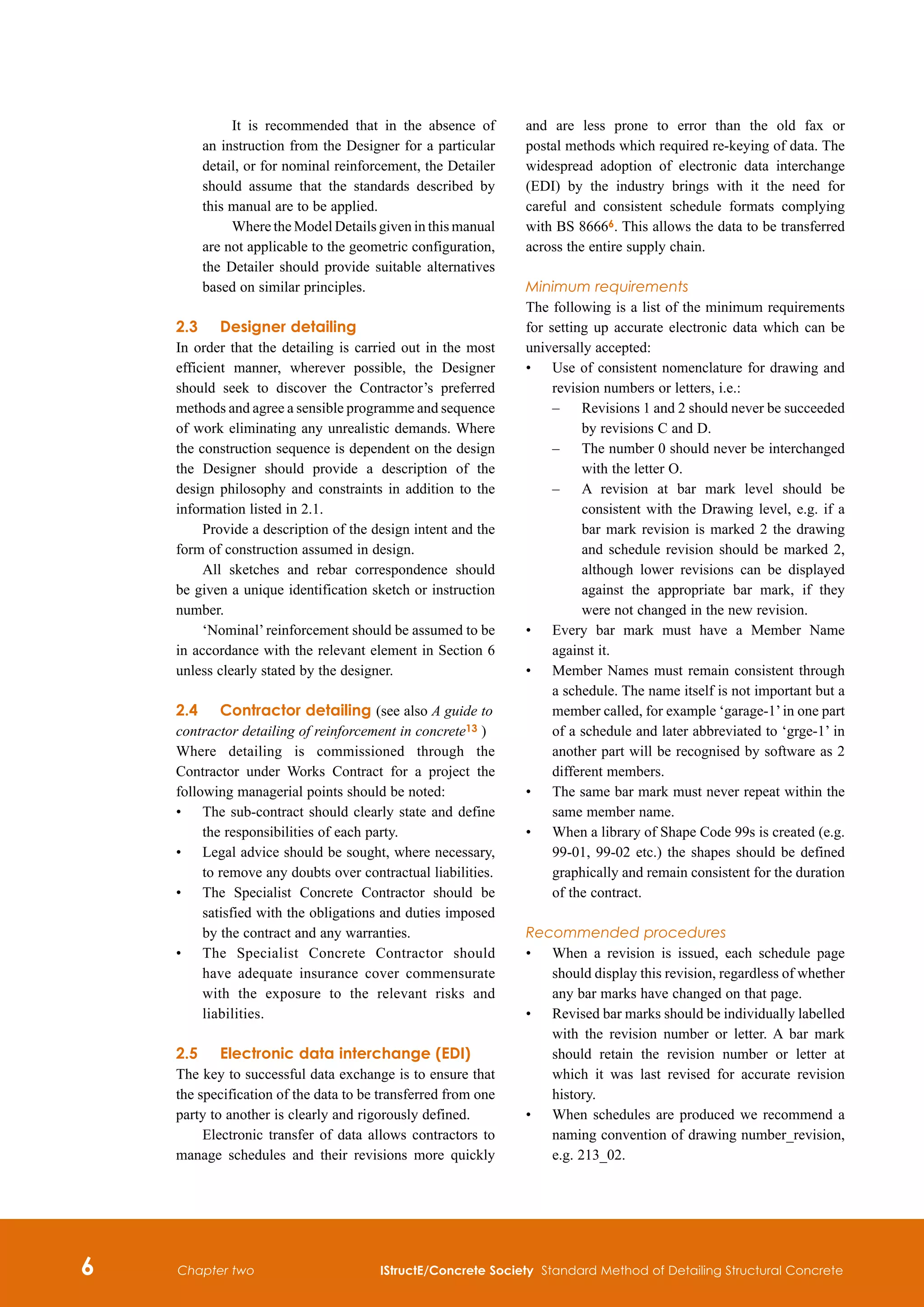
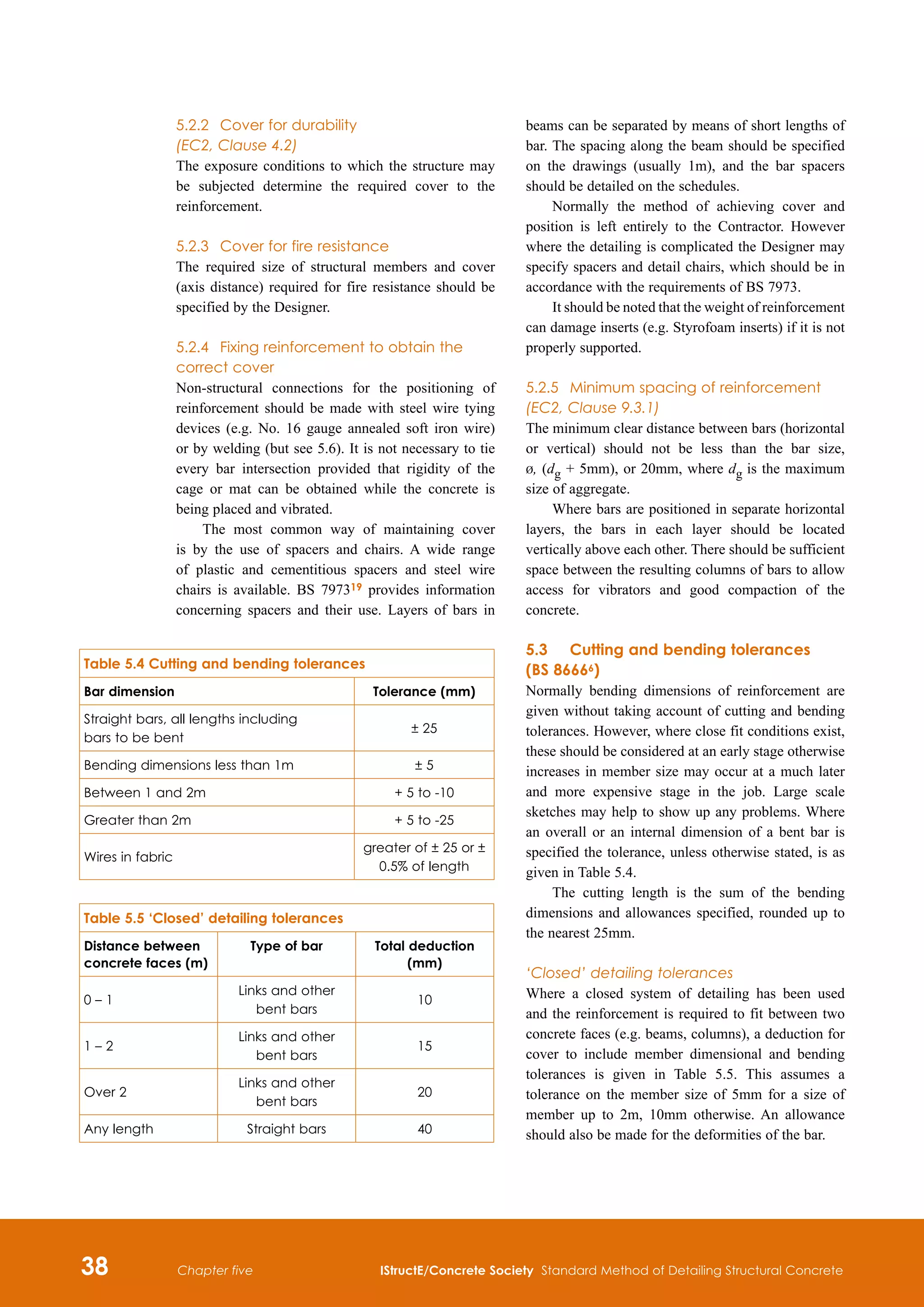
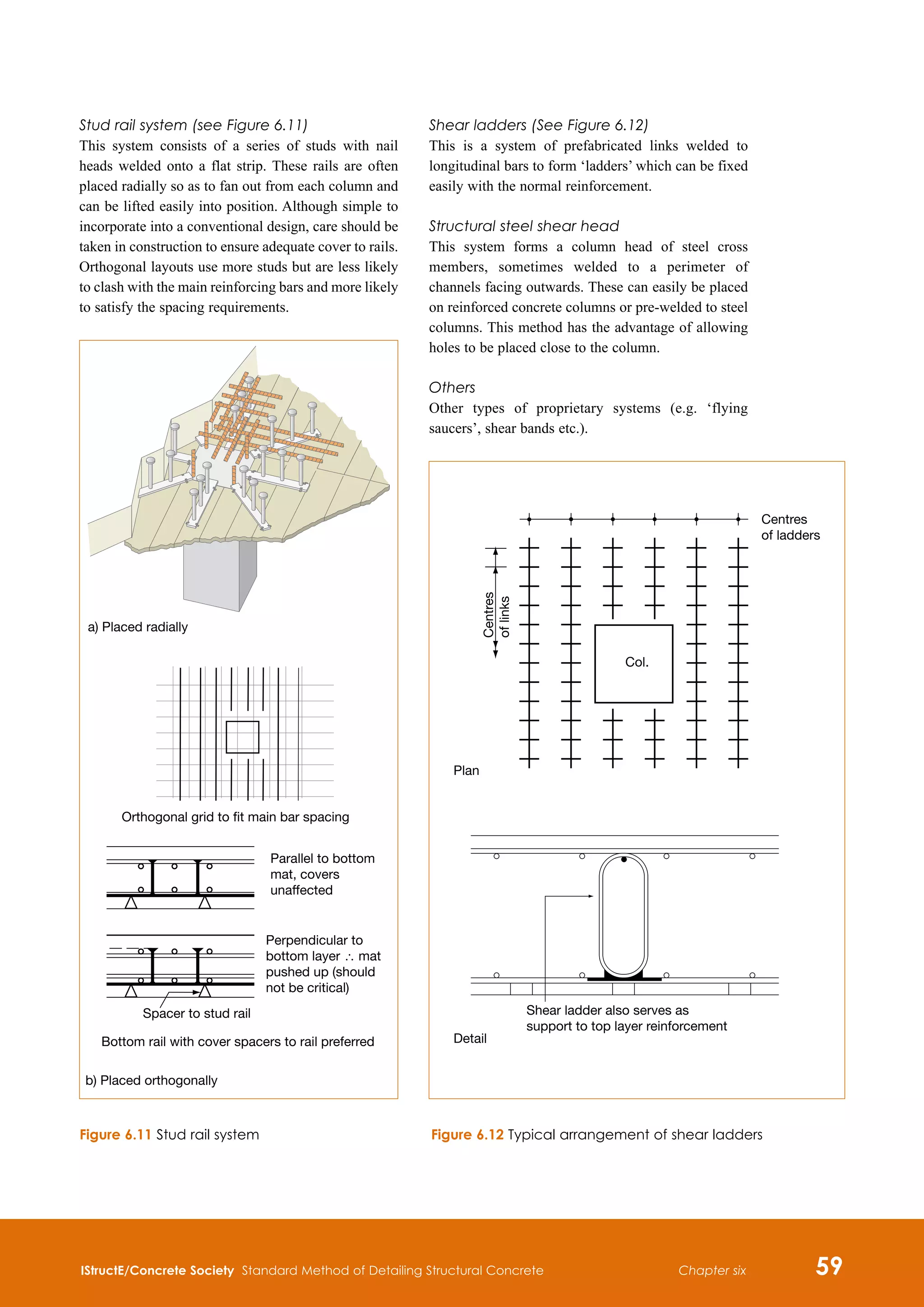
6.2.4 Presentation of working drawings
Single way slabs: [Cover should be shown]
26
H10
10
250
250
800
500
500
500
500
500
500
500
04
05
5
5
4
4
1
1
8
H10
08
300
T2
19
H10
10
250
21 H12 16 T1
10 H10 11 300
U-BARS
10 H10 06 300 B1
19 H12 15 150 T1 AS
10 H12 19 300 U-BARS
LONG LEG B1
19 H10 09 250
U-BARS
(2) (2)
(2) (2)
(2) (2)
07
07
07 07
08
08
08
08
08
22
22
22
22
08
08
08
01
01
01
01
18
17
16
08
08
08
08
08
08
19 H10 09 250
REINF’T REPEATS AS BAY 2–3
61 H12 15 150 T1 AS
61 H12 01 150 B1 AS
4 H10 22 T1
61 H12 15 150 T1 AS
61 H12 01 150 B1 AS
61 H16 13 150 T1 AS
19 H10 08 250 B2
19 H10 10 250
4 H10 21 T1
31 H12 03 150 AP
2 H16 14 T1
U-BARS LONG LEG B1
32 H12 02
3 3 2 2
8 H10 08 300 T2
U-BARS
U-BARS
21 H12 18 300 B2
4 H10 22 T1
30 H12 05 150 B1 AP
31 H12 04 B1
21 H12 17 150 T1 AP
19
H10
08
250
B2
9
H10
08
300
T2
1
H12
20
T2
6
H10
12
300
6T2,
6B2
6
H10
12
300
12
H10
07
300
U-BARS
U-BARS
19
H10
08
250B2
8
H10
08
300
T2
U-BARS
19
H10
08
250
B2
500
1000
1000
1000
250
450
450
500
500
(16)
(4)
(4)
(4)
(4)
(16)
03
02,03
09
09
09
08
18
19
10
08
08
08
04,05
04
04
11
07
05
06
06
05
10
SEE
WALL
DRG
R006
SEE
WALL
DRG
R007
2
–
2
3
–
3
4
–
4
5
–
5
1
–
1
1
1
2
2
3
4
5
5
5
10
16
17
16,17
13
13
13
13
13
15
15
04,05
15
15
15
15
11
19
15
15
15
15
01
01
01
01
01
02,03
02
03
01
01
01
02
(4)
(4)
(4)
(4)
(4)
16
17
(4)
26
H10
10
250
26
H10
08
250
B2
26
H10
08
250
B2
20
H10
08
300
T2
20
H10
08
300
T2
U-BARS
U-BARS](https://image.slidesharecdn.com/detailingstandardmethod3rded2006istructe-211001083748/75/Detailing-standard-method-3rd-ed-2006-istruct-e-75-2048.jpg)
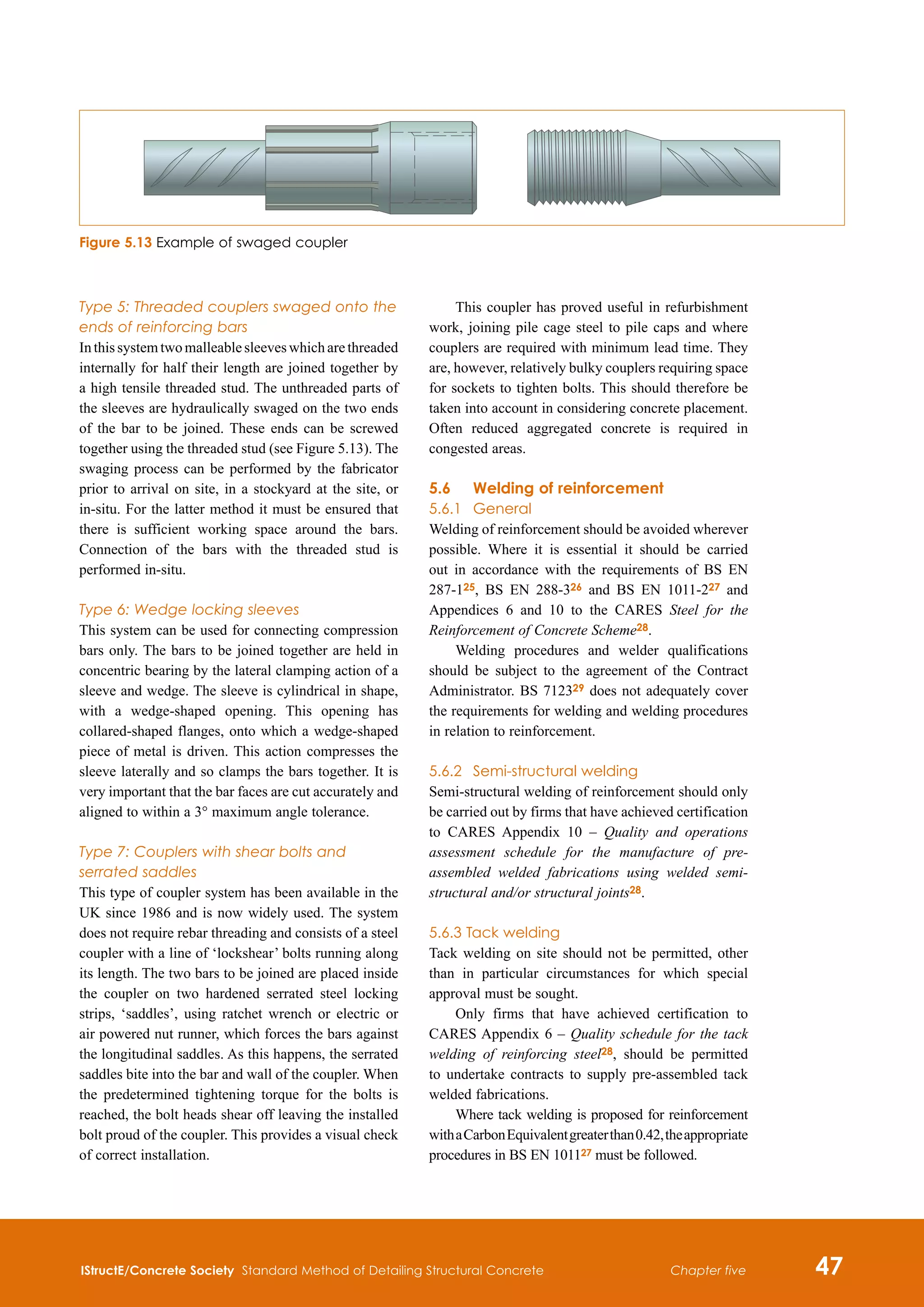
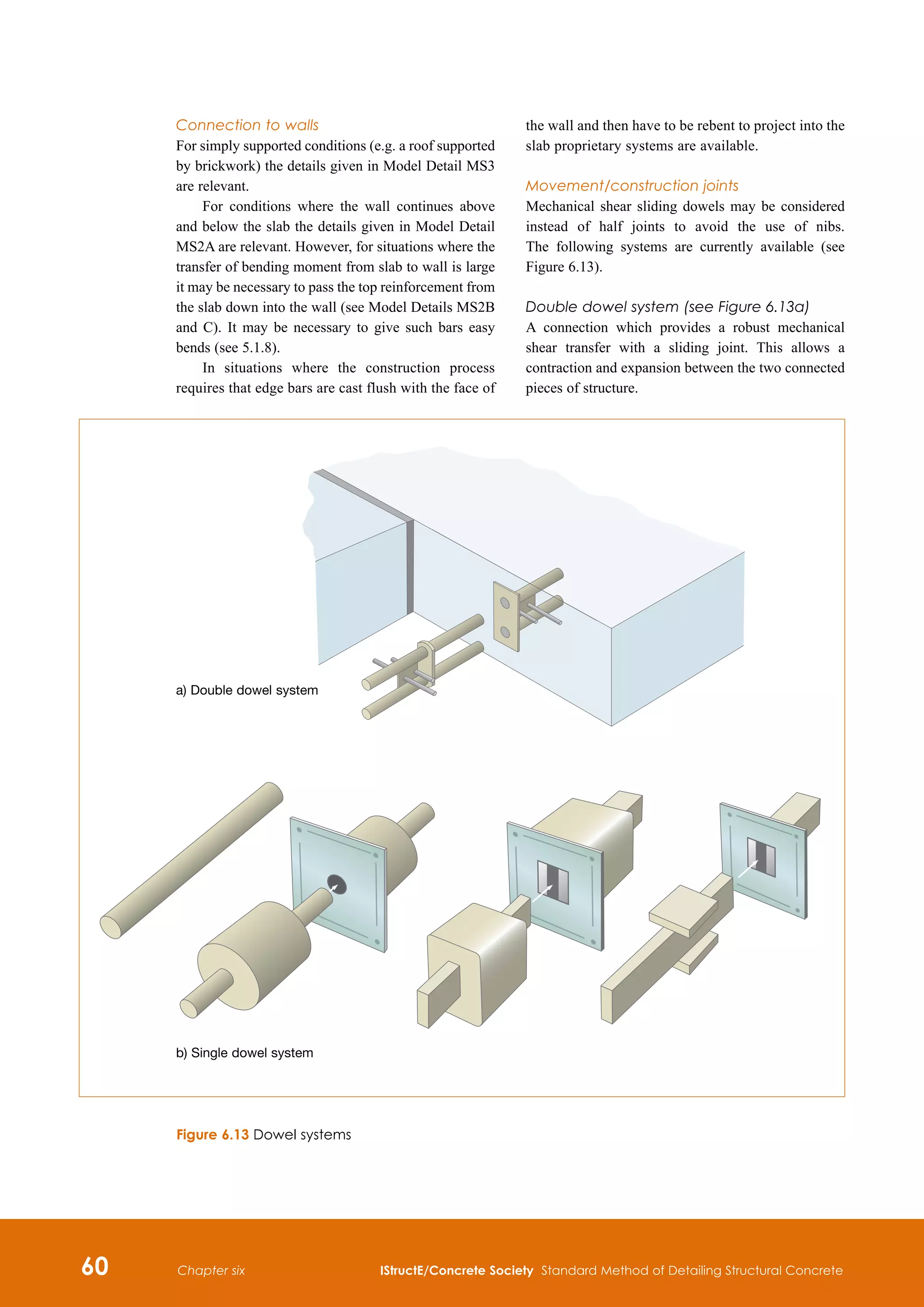
![IStructE/Concrete Society Standard Method of Detailing Structural Concrete 63
Chapter six
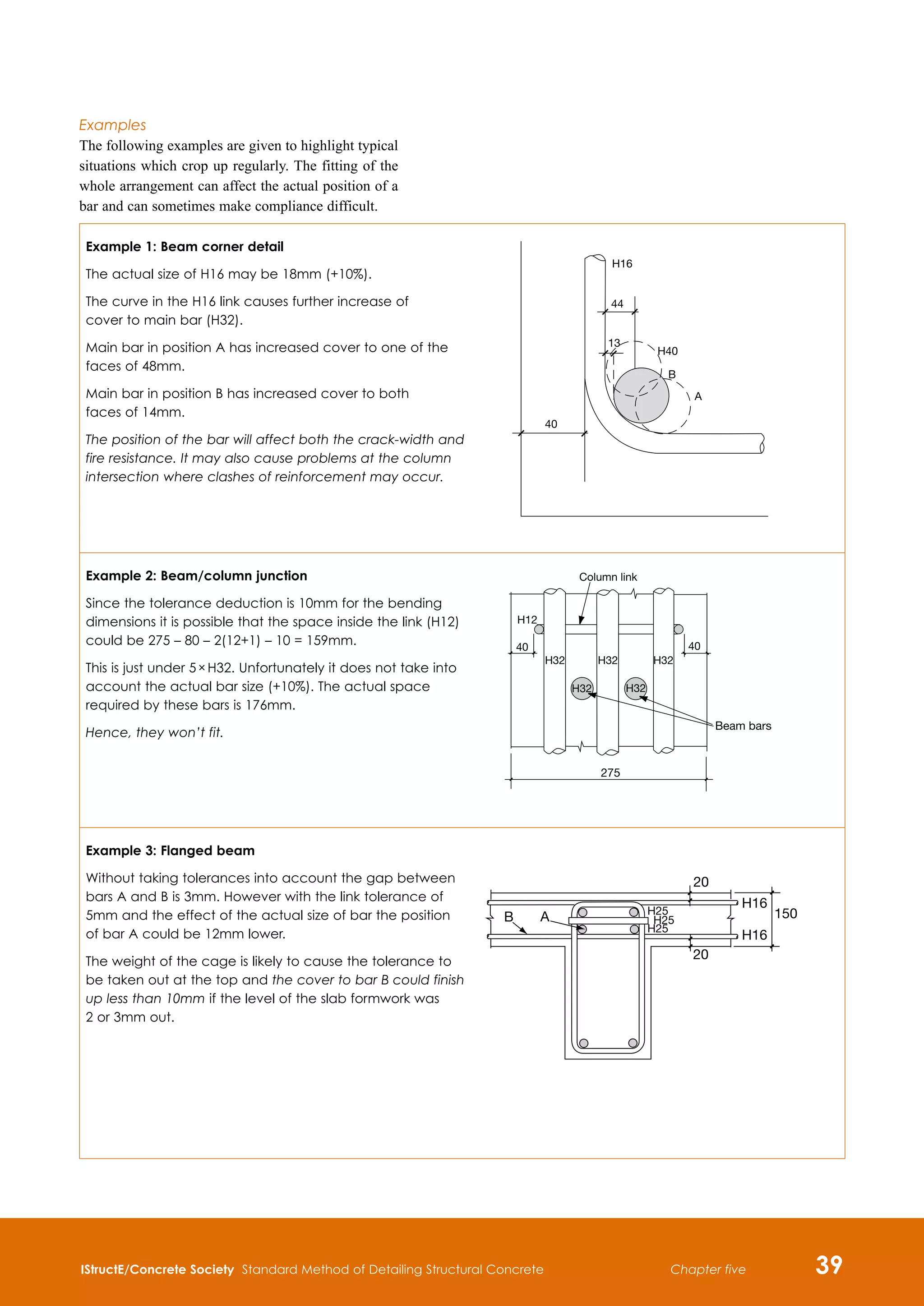
Flat slabs: [Cover should be shown]
11 H16 04 250 T2 AS
(18)
600
600
1200
1500
(18 @ 175)
(18
@
175)
(13 @ 250) (13 @ 250)
(11 @ 250)
(11
@
250)
(16
@
200)
36
H20
03
175
T1
AS
24
H16
01
13
H16
05
7
H12
07
6
H12
08
250
T1
AP
13
H16
06
250
T1
AP
23
H16
02
B1
AP
26
H10
09
250
T1
37
H12
10
250
U-BARS
8
H16
04
350
T1
AS
50
50
09
03 03 03 03
03
02 01 SEE SLAB
DRG. R012
09 10
10
10 01,02
01,02
01,02
05 05,06
5
B
A
Y
A
6 7
A
B
C
05,06
06
2
2
6 7
BAY A
1 – 1
2 – 2 KEY PLAN
08
07
05
01
01
01
02
02
01
02
01
01
01
02
02
01
02
04
03
03
04
03
03
06
05
06
(18)
(18)
700
1500
1500
1200
1200
600
600
01
02
(18 @ 175)
1500
1500
1200
01
02
(13)
(13)
(13)
(13)
(13)
(13)
700
07
08
(18) 36 H20 03 175 T2 AS
24 H16 01
50
50
A
7
B
B
26 H10 09 250 T2
6 H12 07
7 H12 08 250 T2 AP
37 H12 11 250
U-BARS
13 H16 06 250 T2 AP
13 H16 05
23 H16 02 B2 AP](https://image.slidesharecdn.com/detailingstandardmethod3rded2006istructe-211001083748/75/Detailing-standard-method-3rd-ed-2006-istruct-e-76-2048.jpg)
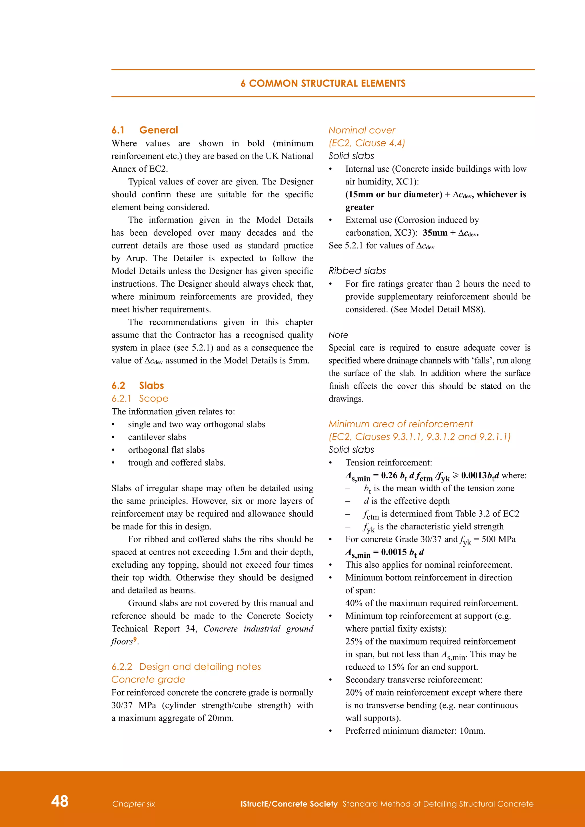
![64 IStructE/Concrete Society Standard Method of Detailing Structural Concrete
Chapter six
Coffered slab: [Cover should be shown]](https://image.slidesharecdn.com/detailingstandardmethod3rded2006istructe-211001083748/75/Detailing-standard-method-3rd-ed-2006-istruct-e-77-2048.jpg)
![IStructE/Concrete Society Standard Method of Detailing Structural Concrete 65
Chapter six
Shear reinforcement for flat slabs: [Cover should be shown]](https://image.slidesharecdn.com/detailingstandardmethod3rded2006istructe-211001083748/75/Detailing-standard-method-3rd-ed-2006-istruct-e-78-2048.jpg)
![74 IStructE/Concrete Society Standard Method of Detailing Structural Concrete
Chapter six
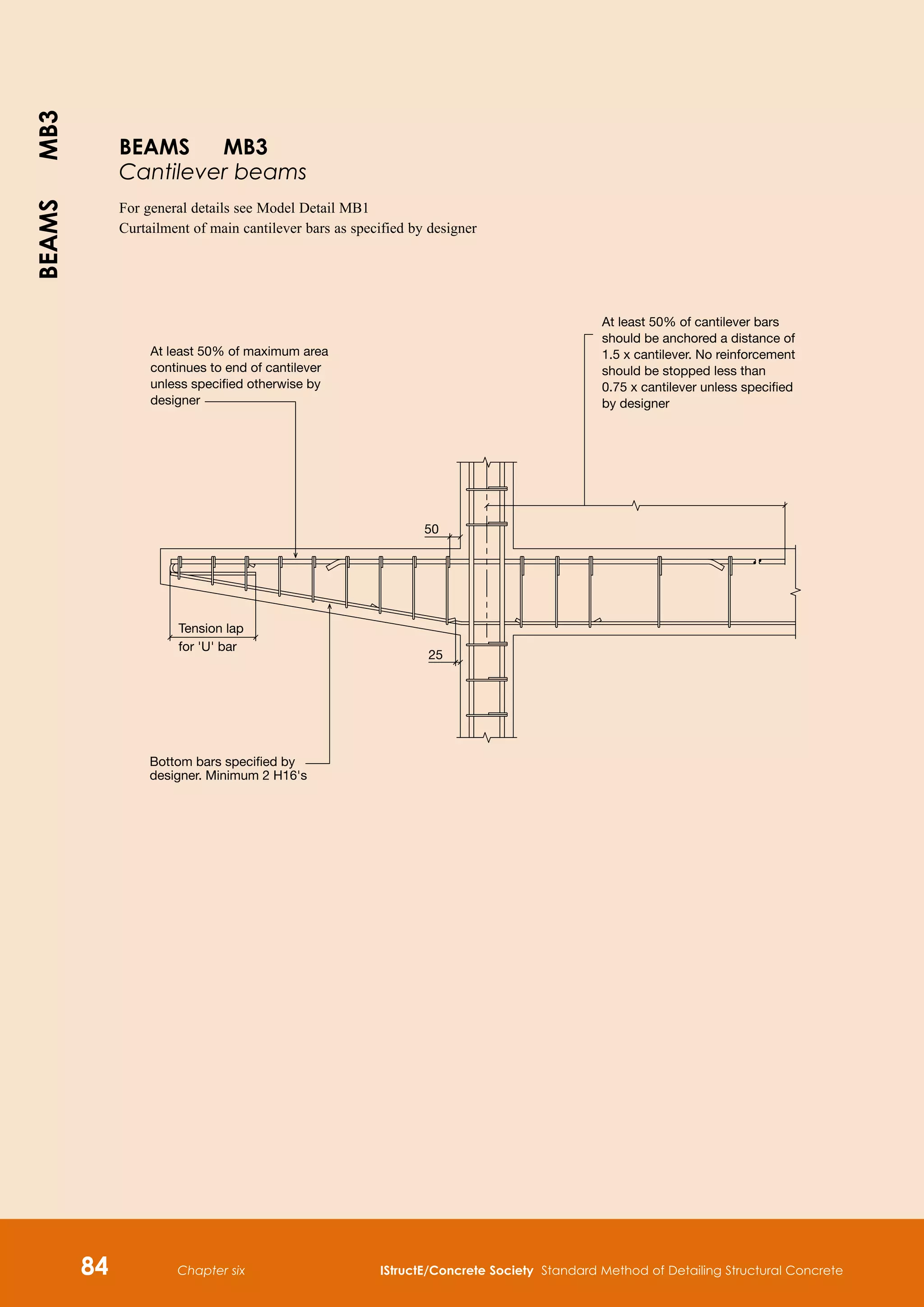
6.3 BEAMS
6.3.1 Scope
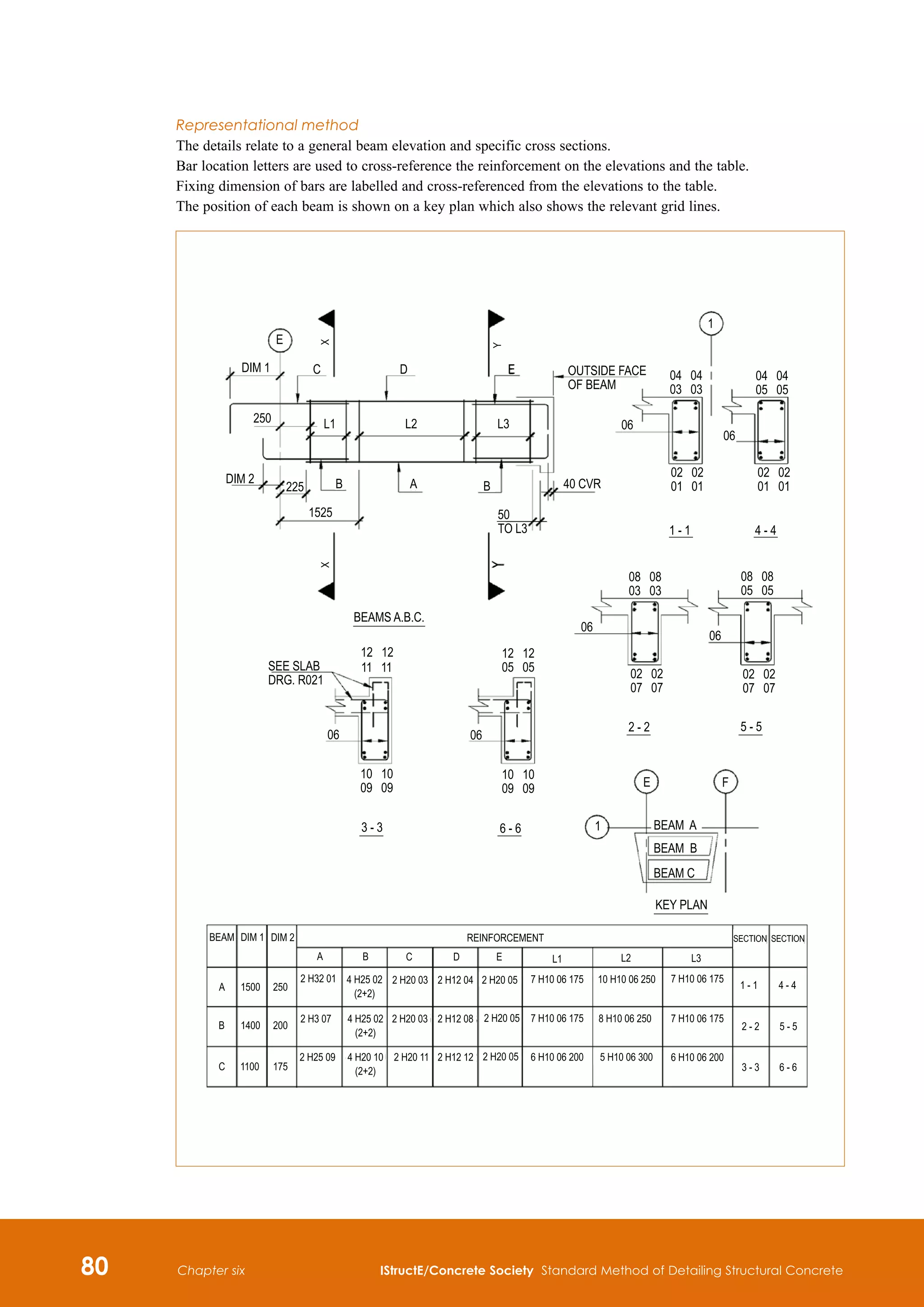
The information given relates to specifically to straight
suspended beams with defined supports.
Ground beams are considered separately in 6.7 of
this manual.
The detailing of holes in beams should not normally
be carried out without specific design instructions. They
can dramatically affect the structural safety of a beam.
6.3.2 Design and detailing notes
Concrete grade
For reinforced concrete the concrete grade is normally
30/37 MPa (cylinder strength/cube strength) with a
maximum aggregate of 20mm.
Nominal cover to all reinforcement
(EC2, Clause 4.4)
•
Internal use: 30mm + Δcdev (Concrete inside
buildings with low air humidity, XC1)
•
External use: 35mm + Δcdev (Corrosion induced
by carbonation, XC3)
See 5.2.1 for values of Δcdev
Note
The cover to grouped bars should be for the equivalent
bar size (see 5.8). Top cover may be determined by
slab or transverse beam reinforcement.
For the purposes of 4 hour fire resistance,
supplementary reinforcement may be required where
the nominal cover exceeds 40mm (See EC2: Part 1.2,
Clause 4.5.2; axis distance to the link reinforcement
exceeds 70mm).
Minimum area of reinforcement
(EC2, Clause 9.2.1.1)
Tension reinforcement
For concrete Grade 30/37 and fyk = 500MPa
As,min H 0.0015 bt d
where bt is the mean width of the tension zone
d is the effective depth
Compression reinforcement
Asc,min H 0.002 Ac
Transverse reinforcement in top flange
As,min H 0.0015 hf l
where
hf is depth of flange
l is the span of the beam
Minimum diameter
12mm
Bar spacing
Minimum horizontal pitch
75mm (sufficient space must be allowed for insertion
of poker vibrator)
100mm for pairs of bars
Minimum vertical pitch
25mm or bar diameter, whichever is greater
Maximum pitch
The following simplified values may normally be
used:
•
Tension bars: The values given in Table 6.3
may normally be used. Unless otherwise stated
it may be assumed that the service stress in the
reinforcement is 310 MPa.
•
Compression bars: 300mm, provided that all
main bars in the compression zone are within
150mm of a restrained bar (see Figure 6.24).
Bars along side of beams
(see EC2, Clause 7.3.3)
For beams with a total depth of 1000mm or more
additional reinforcement is required to control cracking
in the side of faces of the beam. As a simplification
bars (16mm) should be placed along the sides inside
the links at a maximum pitch of 250mm.
Links
Asw/s bw H 0.085%
where
Asw
is the cross-sectional area of the 2 legs
of link
bw
is the average breadth of concrete
below the upper flange
s
spacing of link (G 15b of main
compression bars)
Preferred minimum diameter 8mm.
Table 6.3 Maximum bar spacing for
crack control
Steel stress
[MPa]
Maximum bar spacing [mm]
wk=0.4mm wk=0.3mm wk=0.2mm
160 300 300 200
200 300 250 150
240 250 200 100
280 200 150 50
310 165 115 -
320 150 100 -
360 100 50 -
Note
The values in the table are reproduced from
EC2, Table 7.3N](https://image.slidesharecdn.com/detailingstandardmethod3rded2006istructe-211001083748/75/Detailing-standard-method-3rd-ed-2006-istruct-e-87-2048.jpg)
![IStructE/Concrete Society Standard Method of Detailing Structural Concrete 75
Chapter six
Link spacing
Minimum pitch
100mm or [50 + 12.5 (No. of legs)]mm, whichever is
greater. This ensures that the space taken up by links
along the beam is not overlooked.
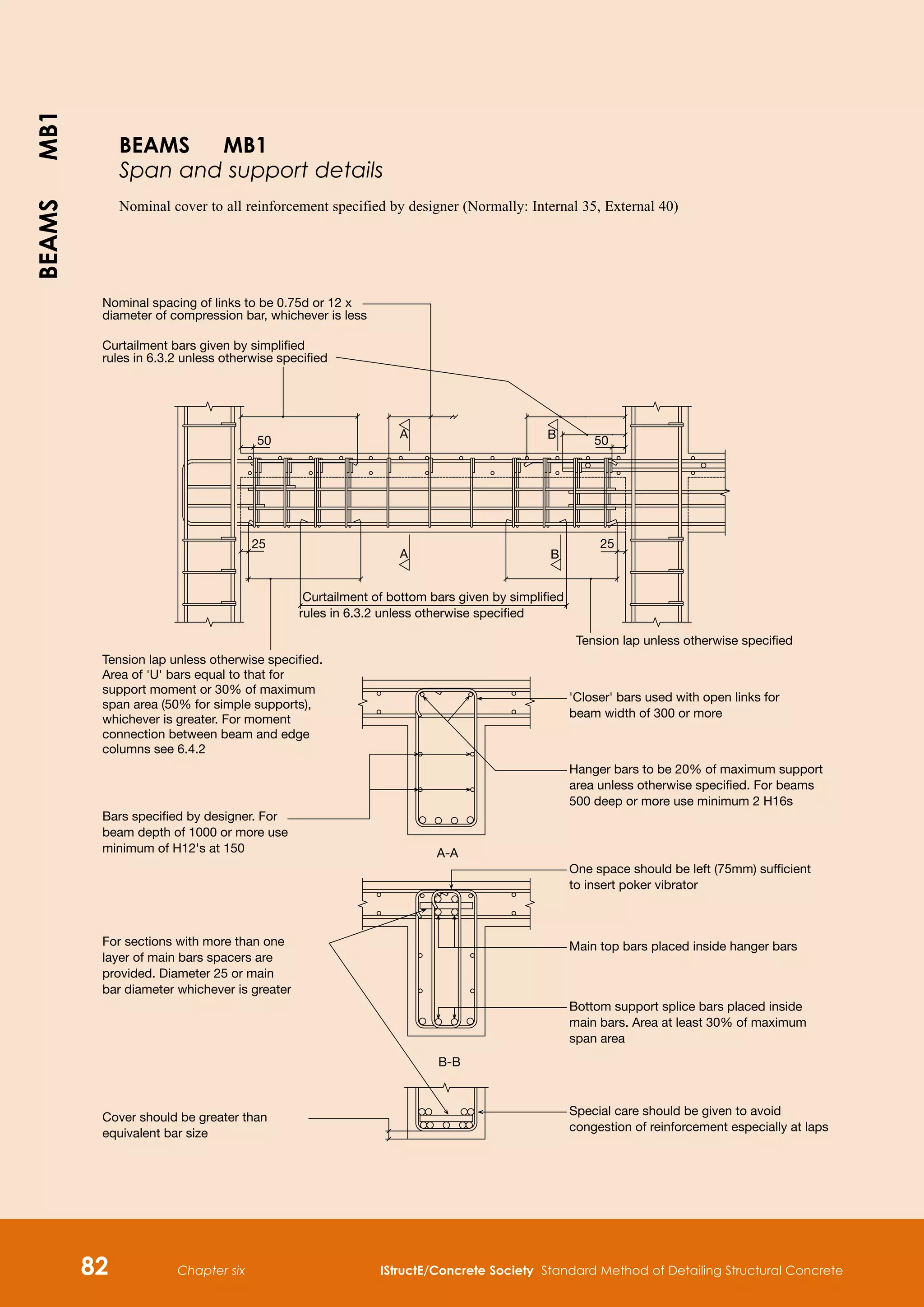
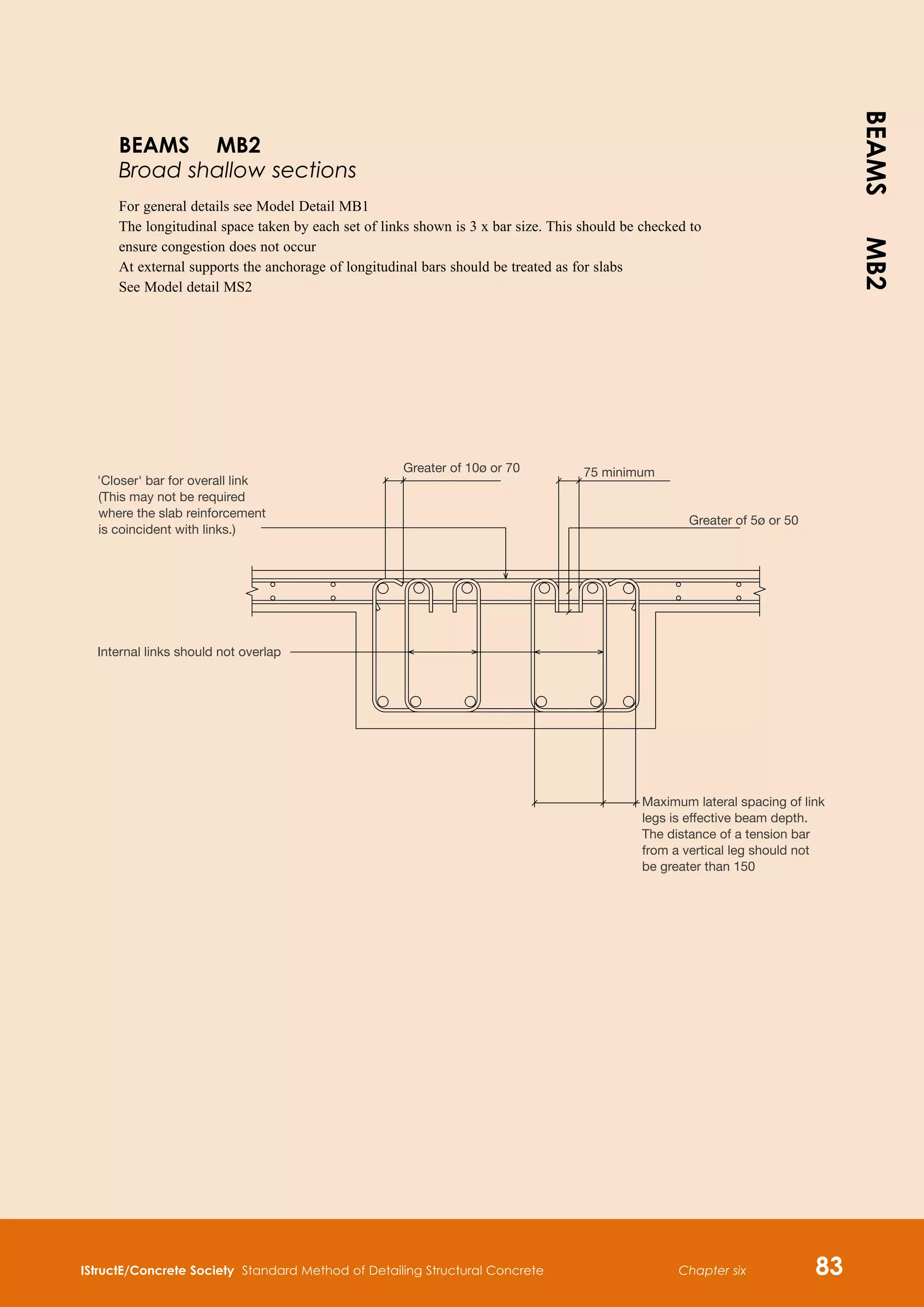
(See Model Details MB1 and MB2)
Maximum pitch
300mm or 0.75d or 12 × diameter of compression bar,
whichever is least.
Maximum lateral pitch of legs
600mm or 0.75d. The distance of a tension or
compression bar from a vertical leg should not be
greater than 150mm.
Anchorage and lapping of bars
(EC2, Clauses 8.4 and 8.7)
Minimum anchorage length
Greater of 10b or 100mm.
For high yield steel, 500 Grade and deformed
bars, Table 6.4 gives typical anchorage and lap lengths
for ‘good’ and ‘poor’ bond conditions (see 5.4).
Curtailment of longitudinal
reinforcement in beams
(EC2, Clauses 8.4.4 and 9.1.2.3)
Figure 6.14 shows a typical moment envelope.
The tension force, FE, to be anchored may be
determined by the shift rule:
FE = |VEd| al/z + NEd (See Figure 6.14 and EC2,
Expression (9.3))
The required anchorage length, lbd, is taken from
the line of contact between beam and support.
Transverse pressure may be taken into account for
‘direct’ supports (a5 in Table 8.2 of EC2, Clause 8.4.4).
The Designer should specify the curtailment
length lbd + al. Where nothing is specified the Detailer
should assume that al = 1.25d.
Simplified curtailment rules
The following simplified rules with ‘flexible
detailing’ (see Figure 6.15) may be applied to the
secondary longitudinal reinforcement and for the main
longitudinal reinforcement where:
•
the characteristic imposed load, Qk does not
exceed the characteristic dead load, Gk
•
the loads are substantially uniformly distributed
over three or more spans
•
the variation in span length does not exceed 15%
of the longest span.
The effective span, L, need not be taken greater than:
(the clear span + d).
Hanger bars
At least 20% of maximum support area or sufficient
for compression area required, whichever is greater,
should be carried to 25mm from each support.
Diameter: 16mm (recommended size).
Table 6.4 Typical values of anchorage and lap lengths
Bond
conditions
Length in bar diameters
fck /fcu =
25/30
fck /fcu =
28/35
fck /fcu =
30/37
fck /fcu =
32/40
Full tension and compression anchorage
length, lb,rqd
1
good 36 34 32 31
poor 48 45 43 41
Full tension and compression lap length2
good 42 39 37 35
poor 56 52 49 47
Notes
1
It is assumed that the bar size is not greater than 32mm and a1, a2, a4 and a5 all equal 1
and that a3 = 0.9 (l = 1.35 and K = 0.05).
2
It is assumed a6 = 1.15 (not more than 33% of the bars are lapped at one place).
For other situations refer to EC2, Clause 8.4.4.
Envelope of (MEd /z + NEd )
Acting tensile force
Resisting tensile force
lbd
lbd
lbd
al
al
lbd
lbd
lbd
lbd
lbd
Ftd
Ftd
Ftd
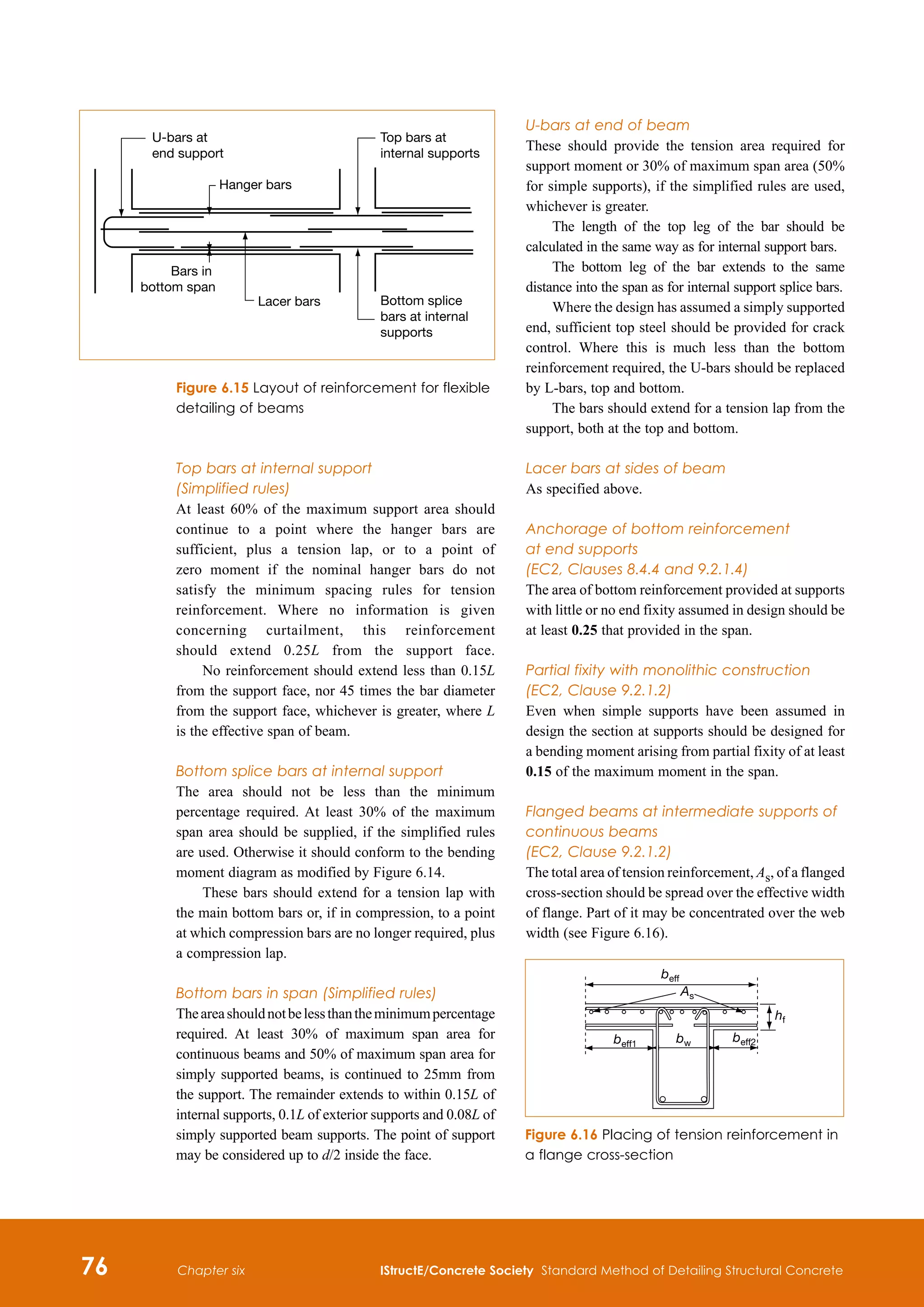
Figure 6.14 Illustration of the curtailment of
longitudinal reinforcement](https://image.slidesharecdn.com/detailingstandardmethod3rded2006istructe-211001083748/75/Detailing-standard-method-3rd-ed-2006-istruct-e-88-2048.jpg)