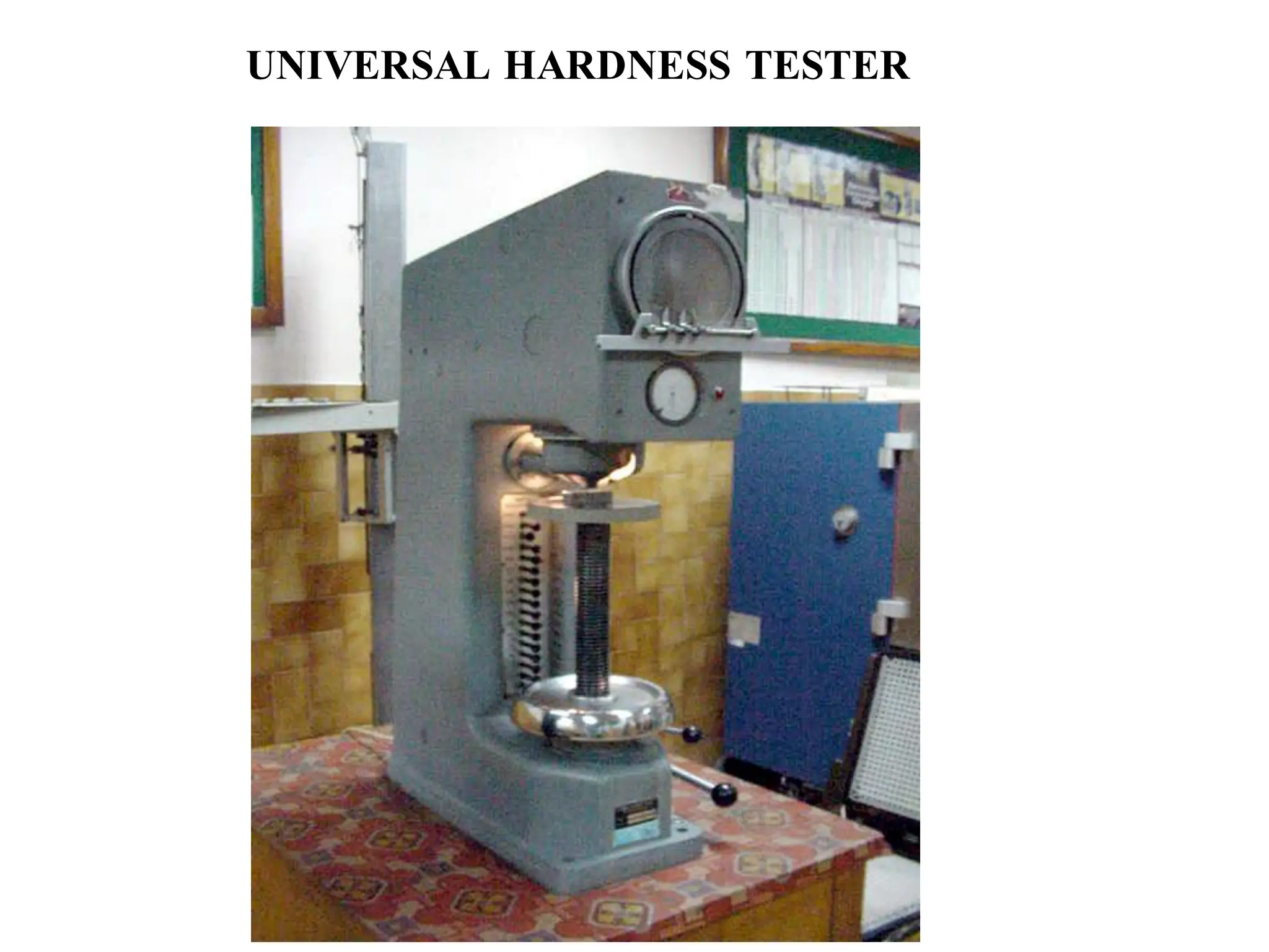
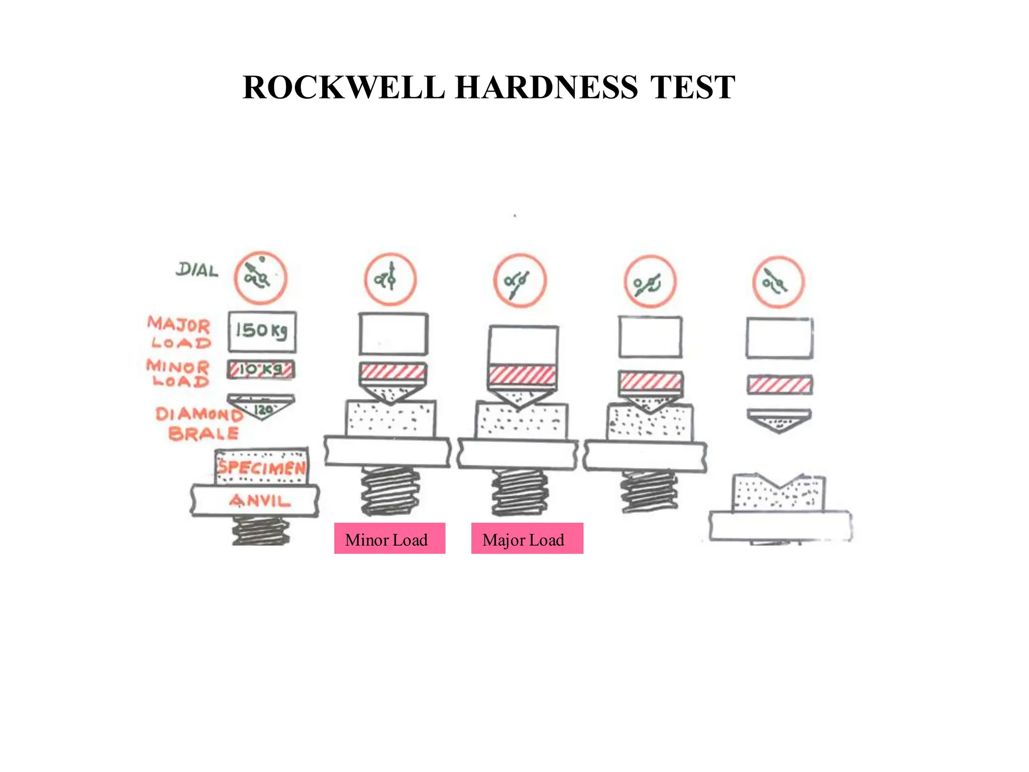
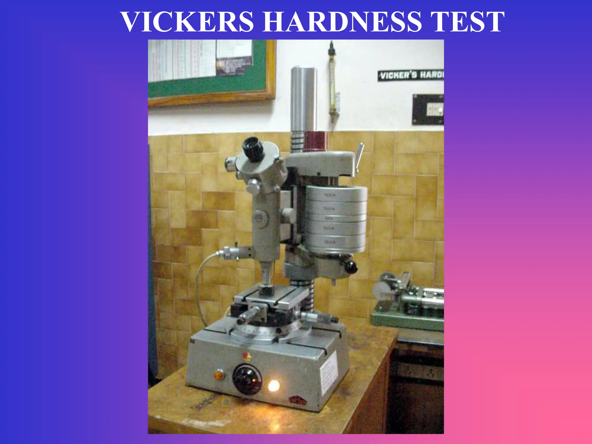
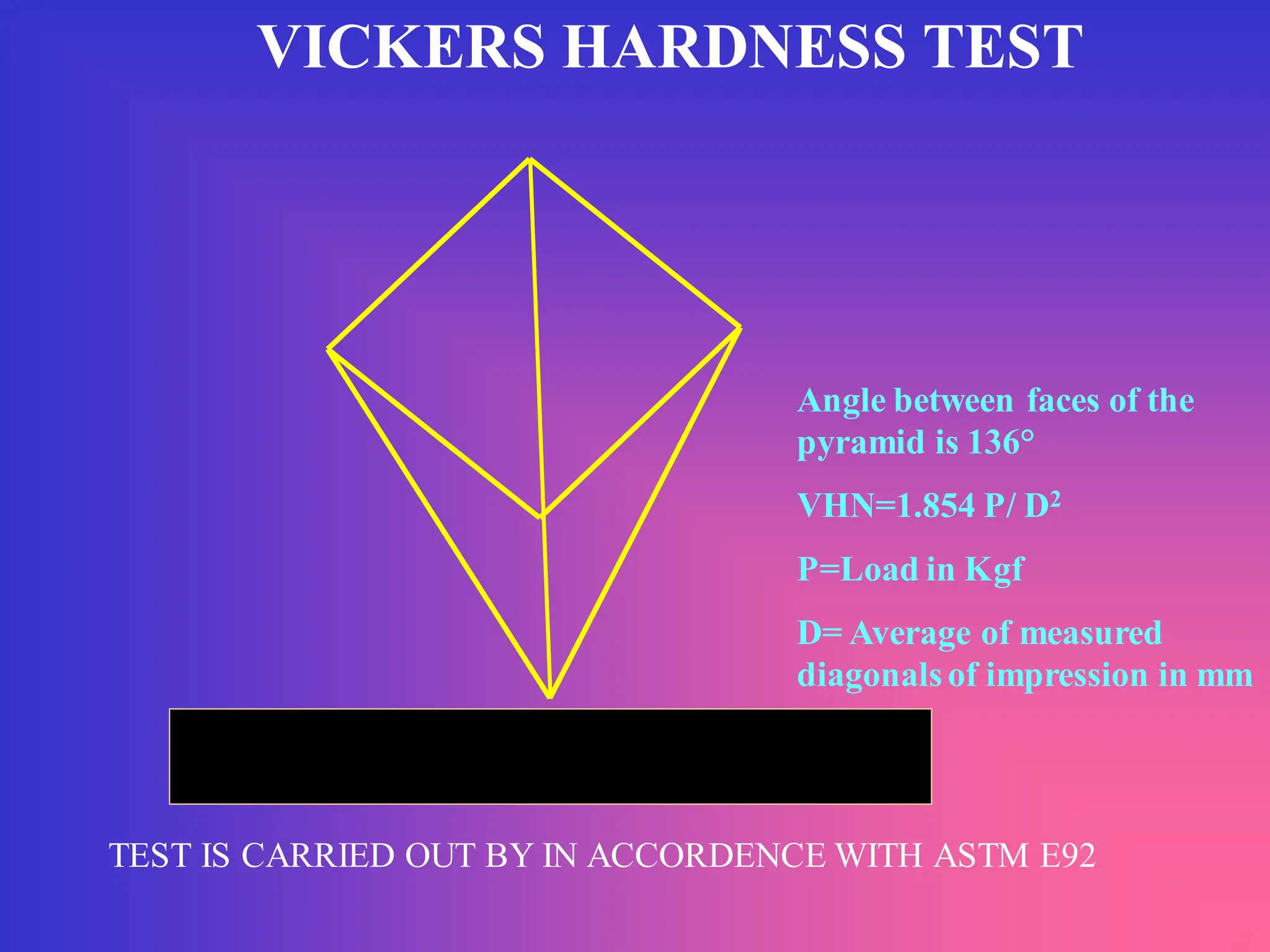
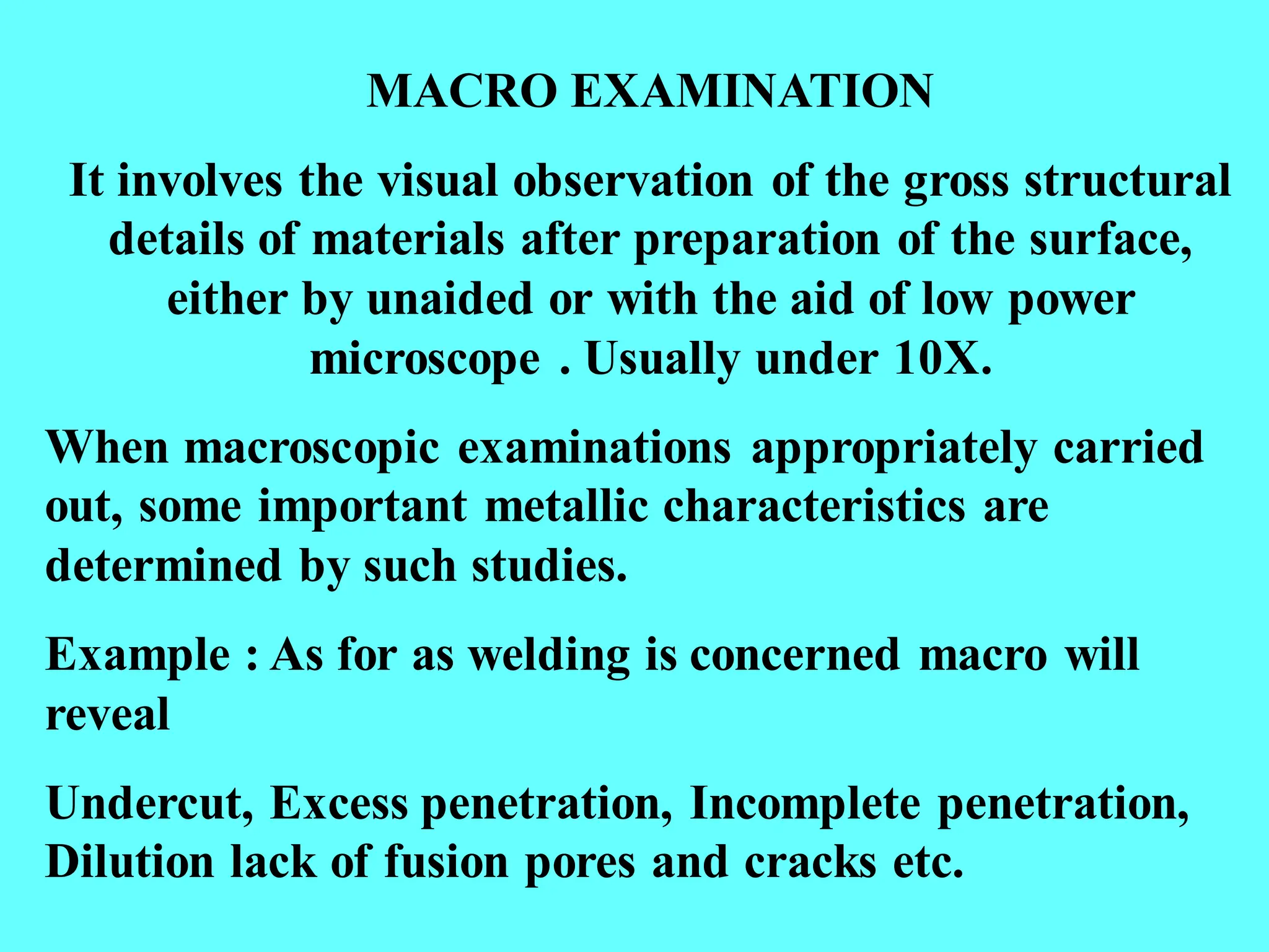
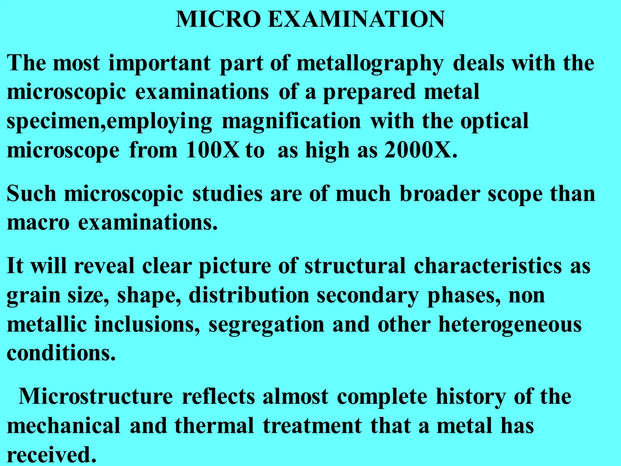
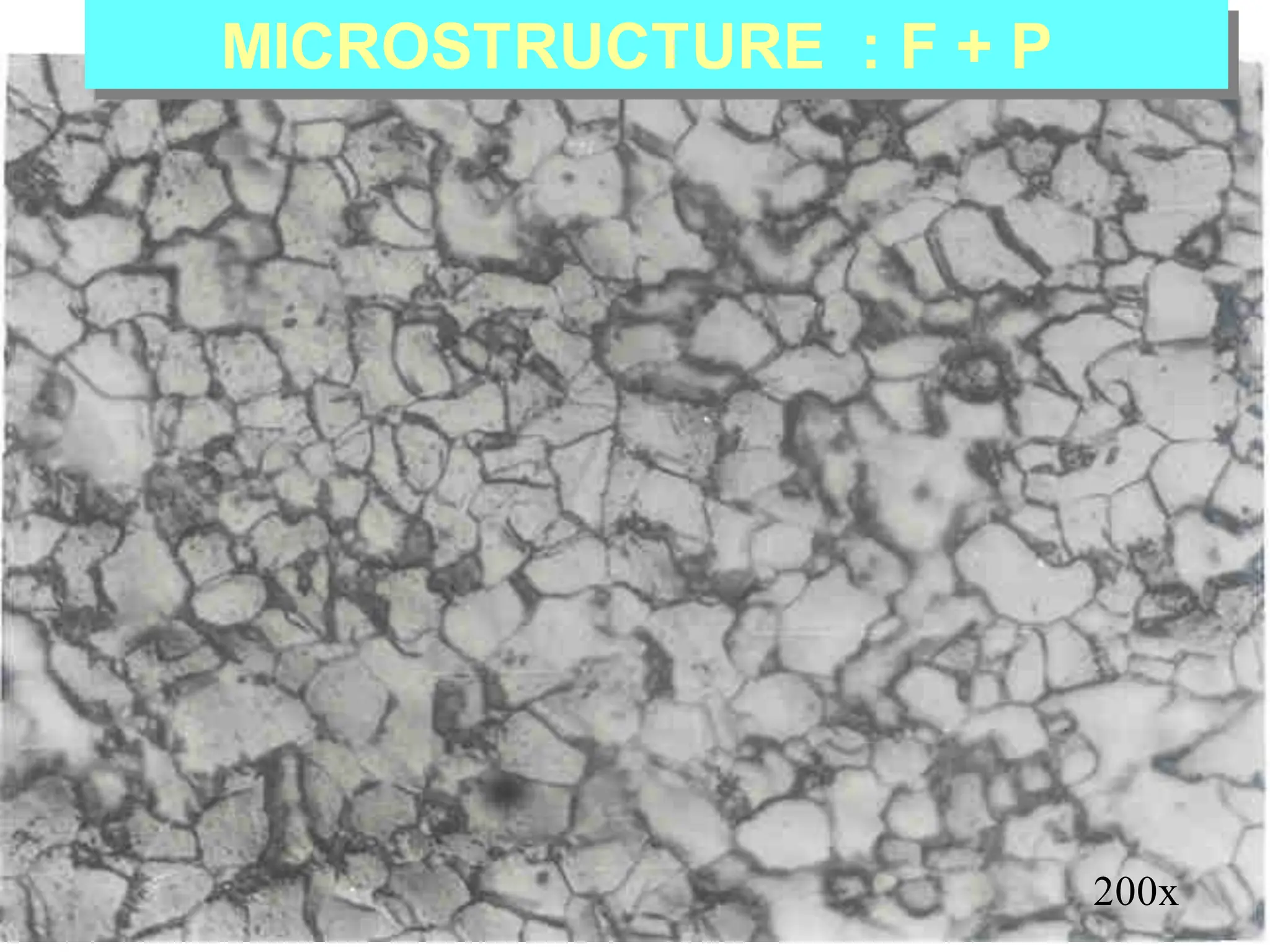
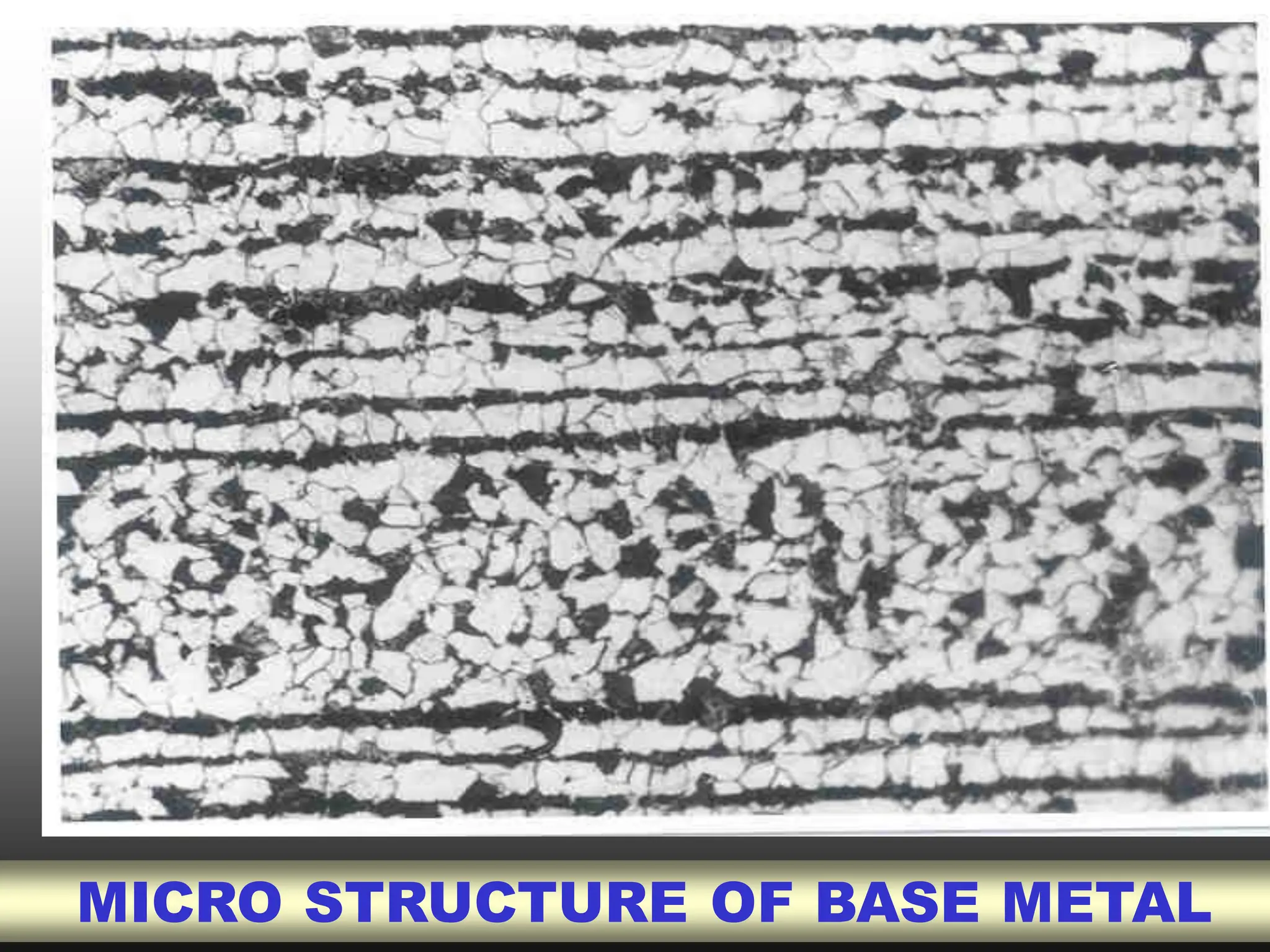
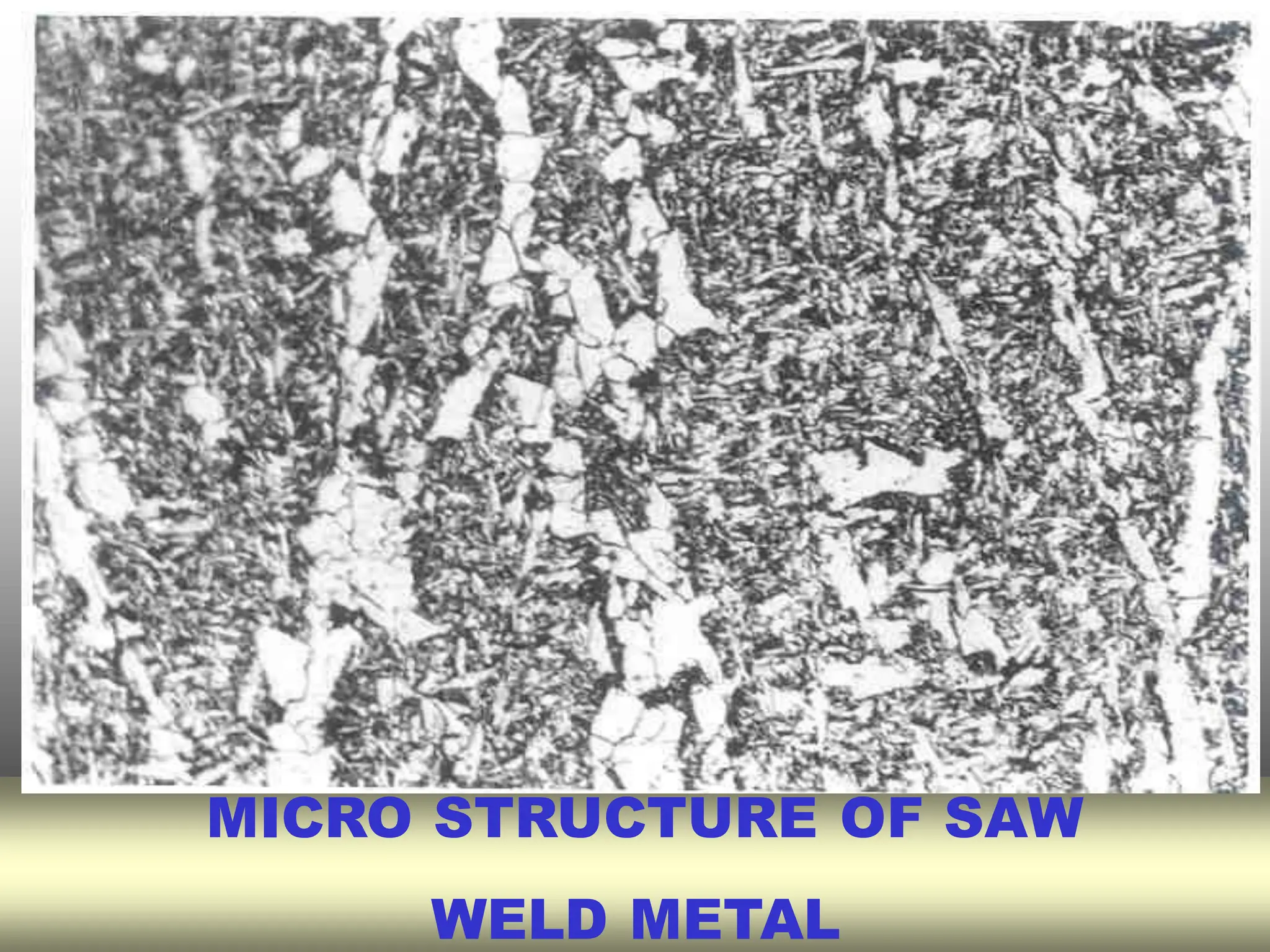
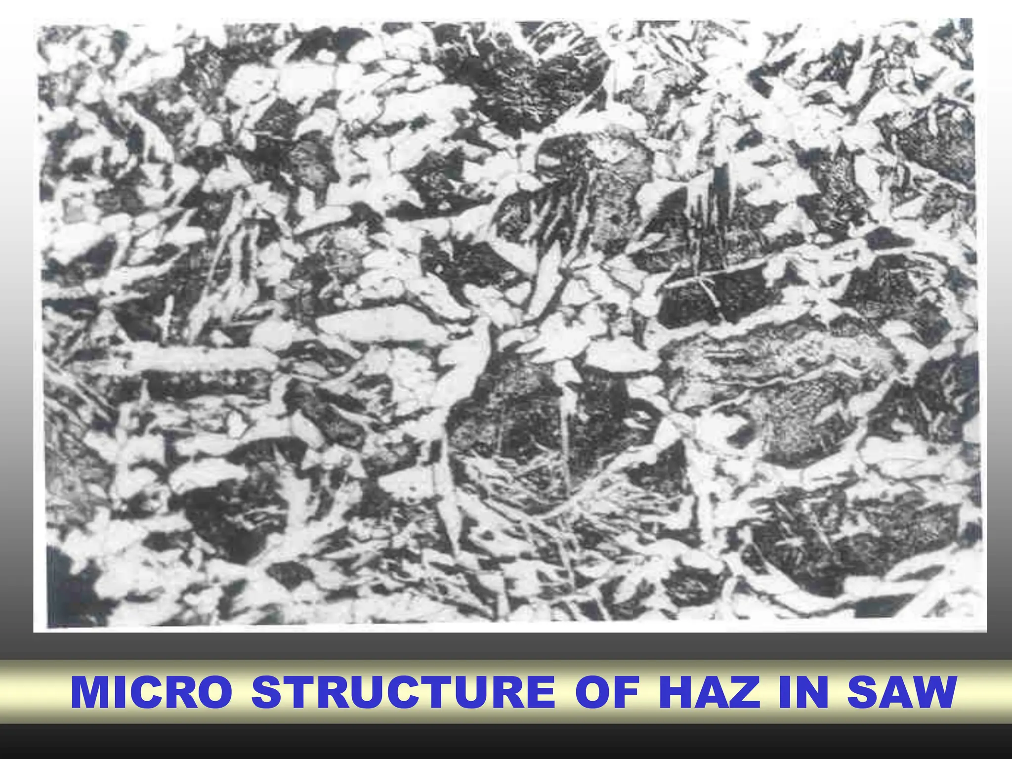
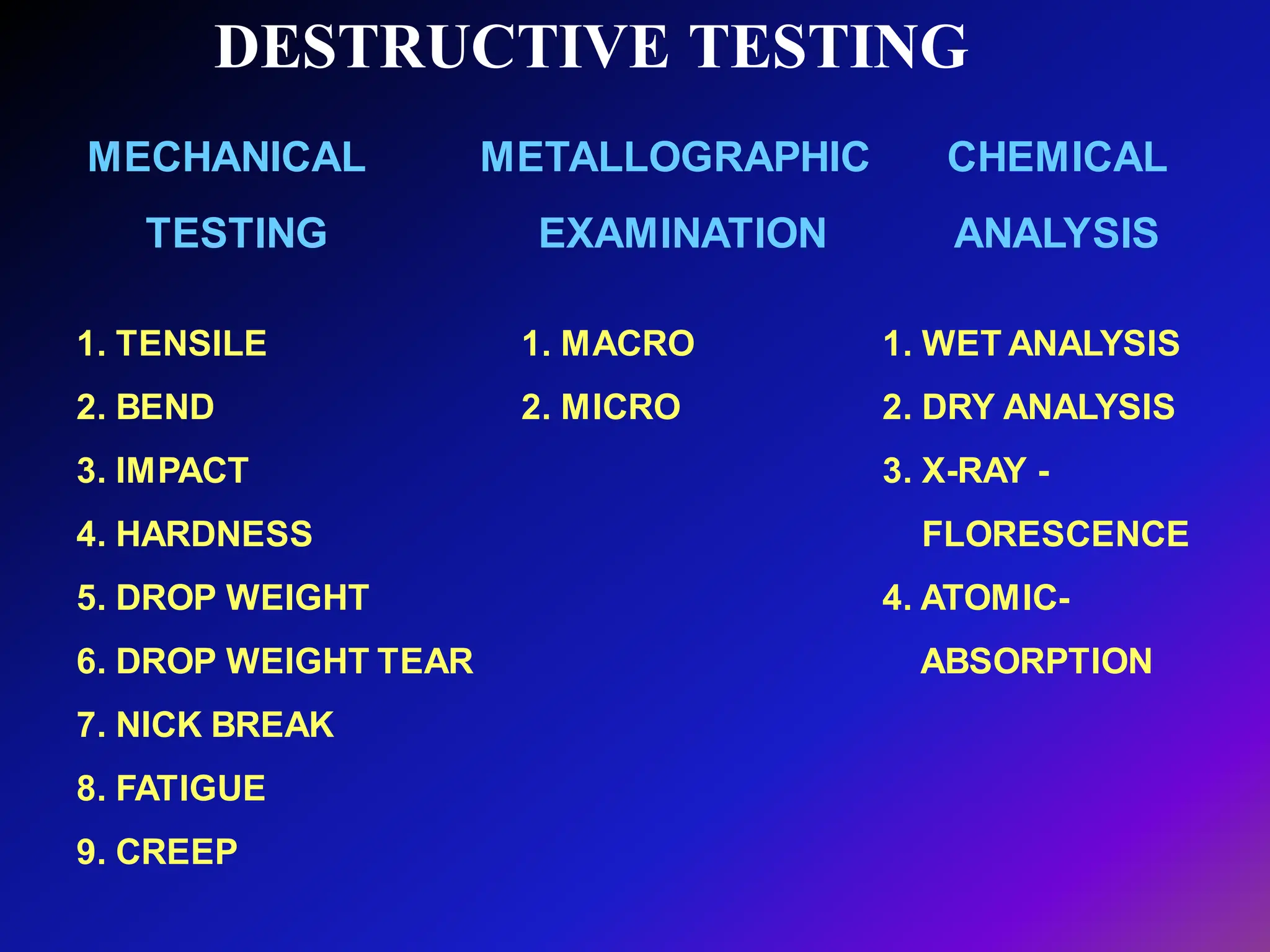
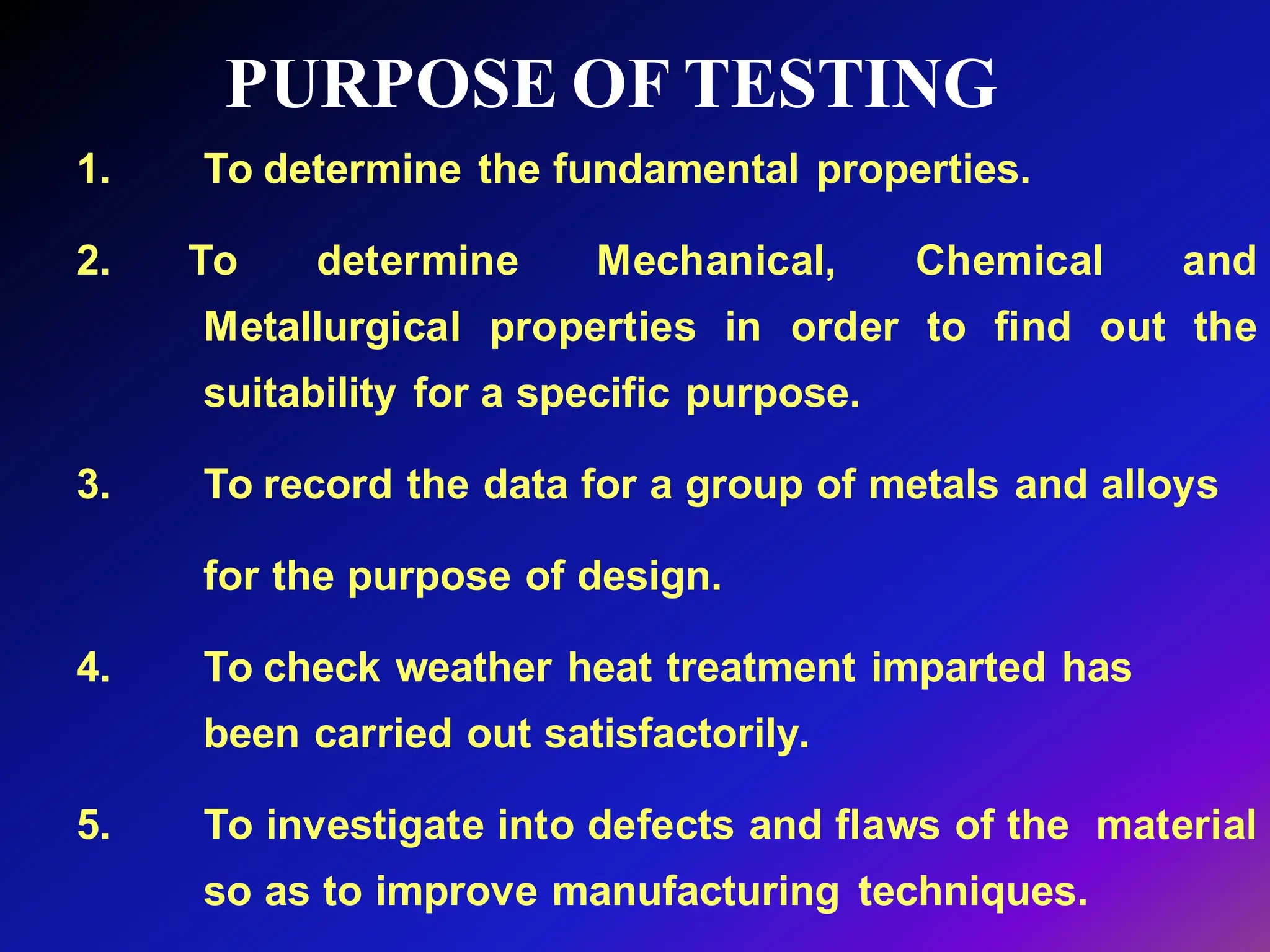
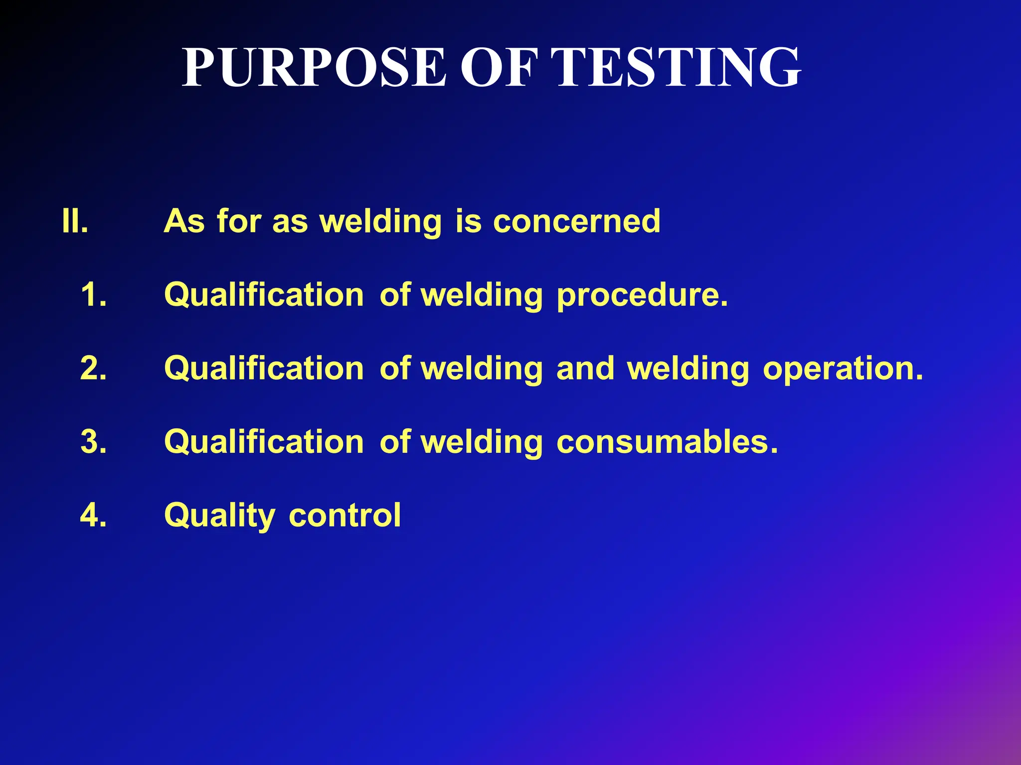
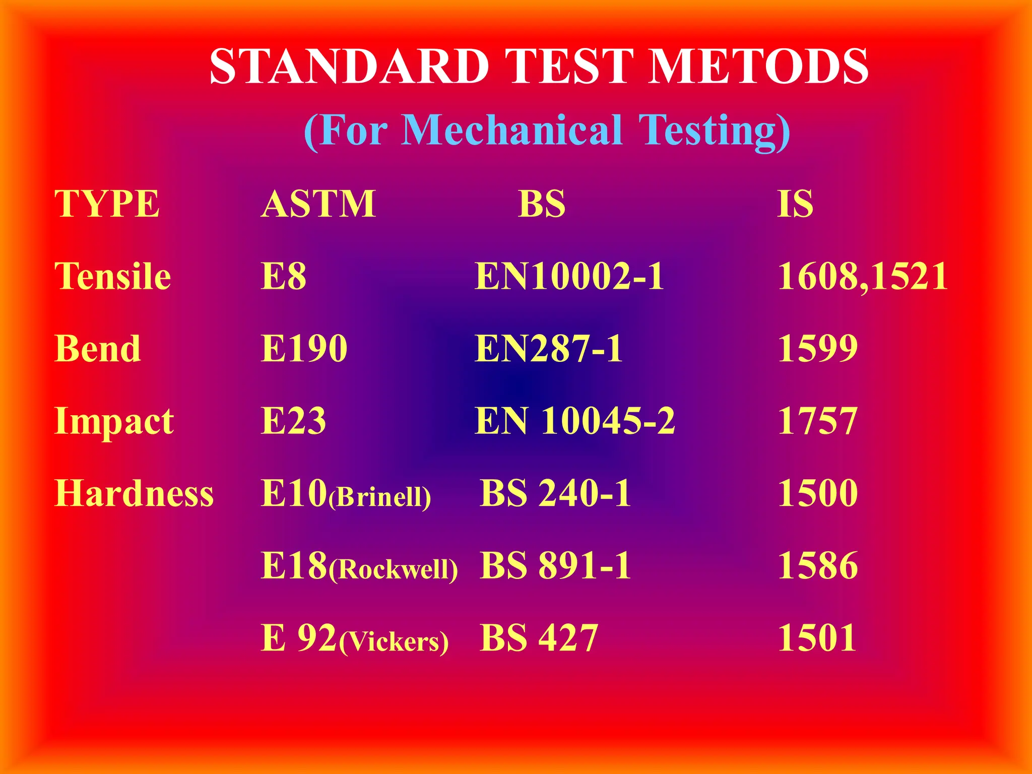
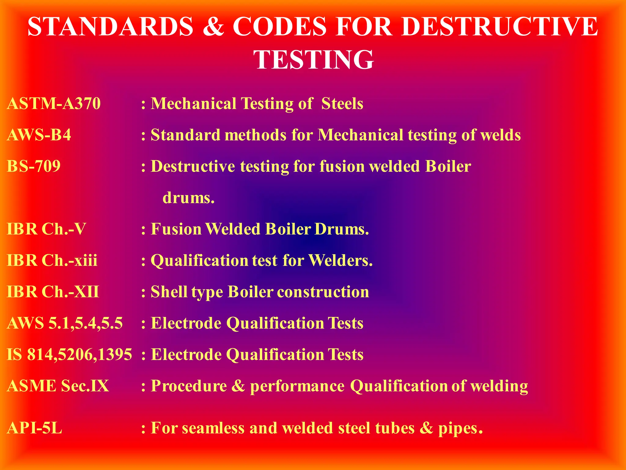
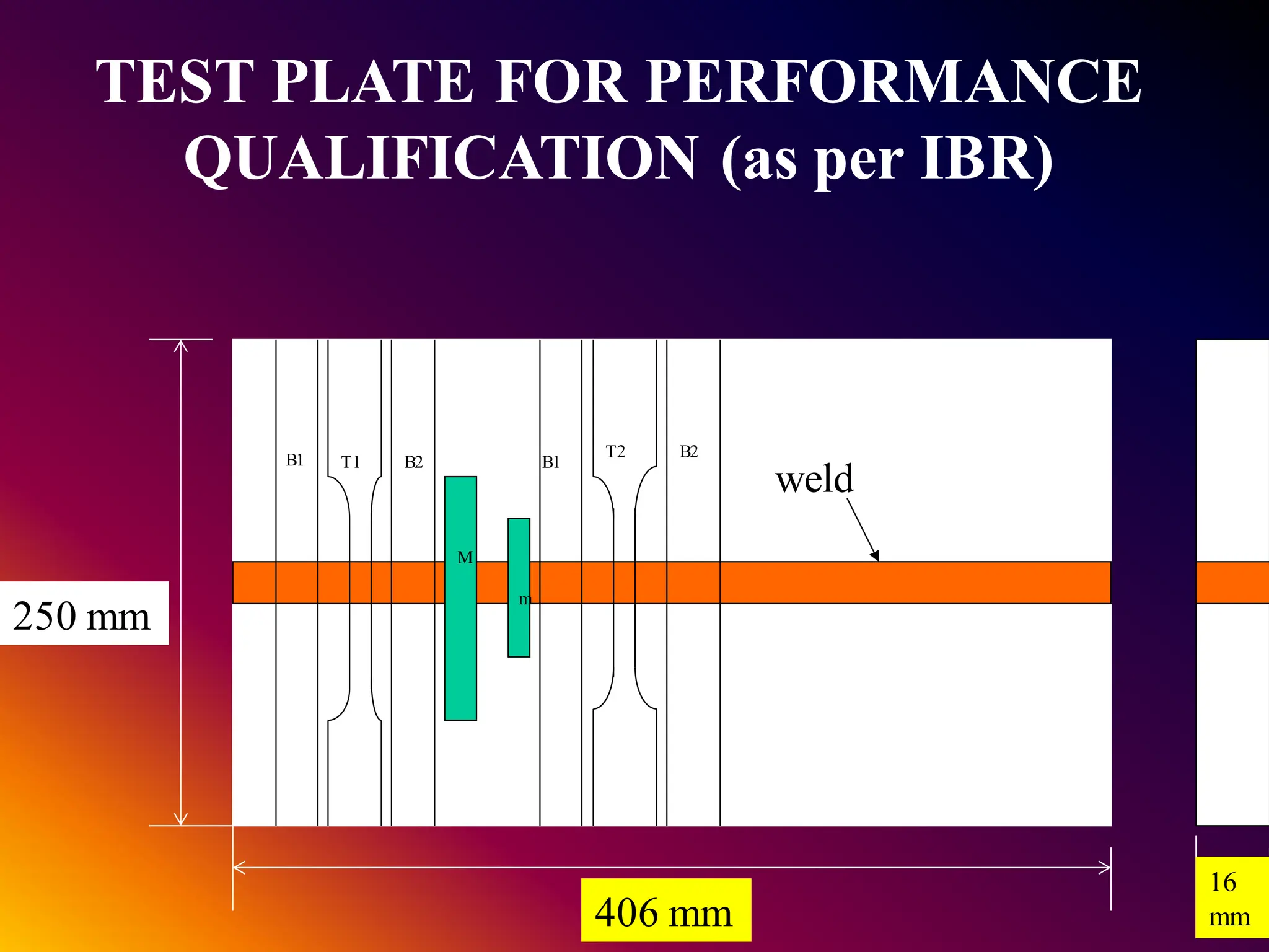
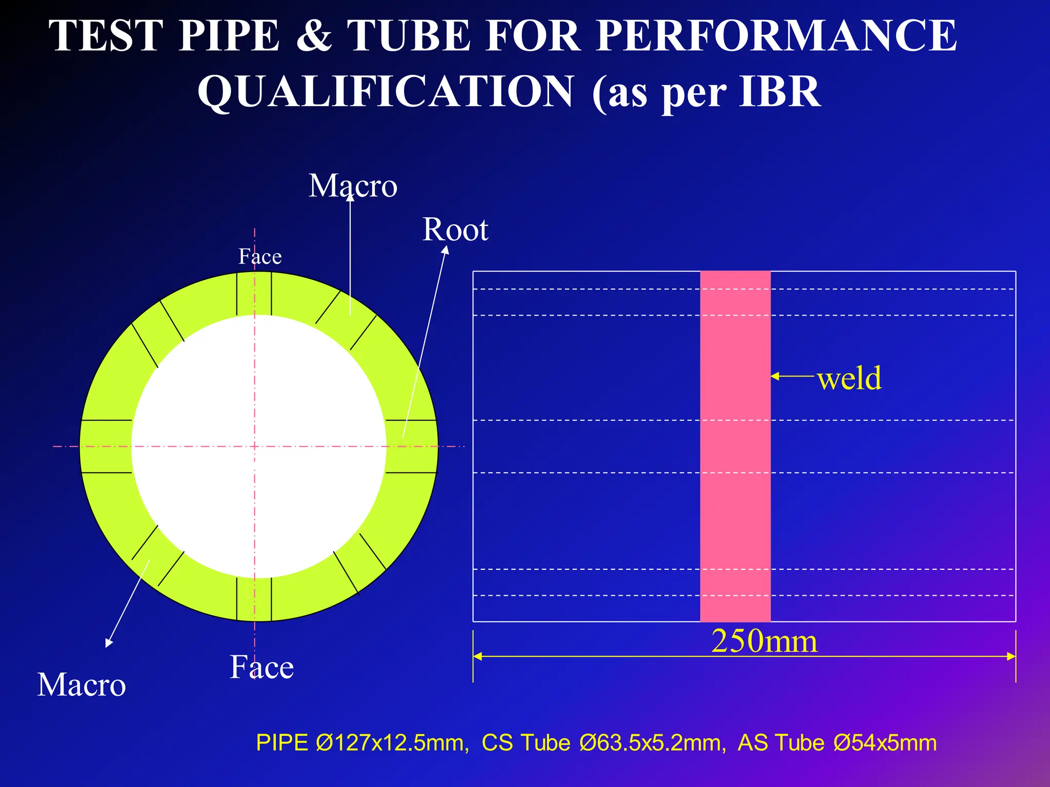
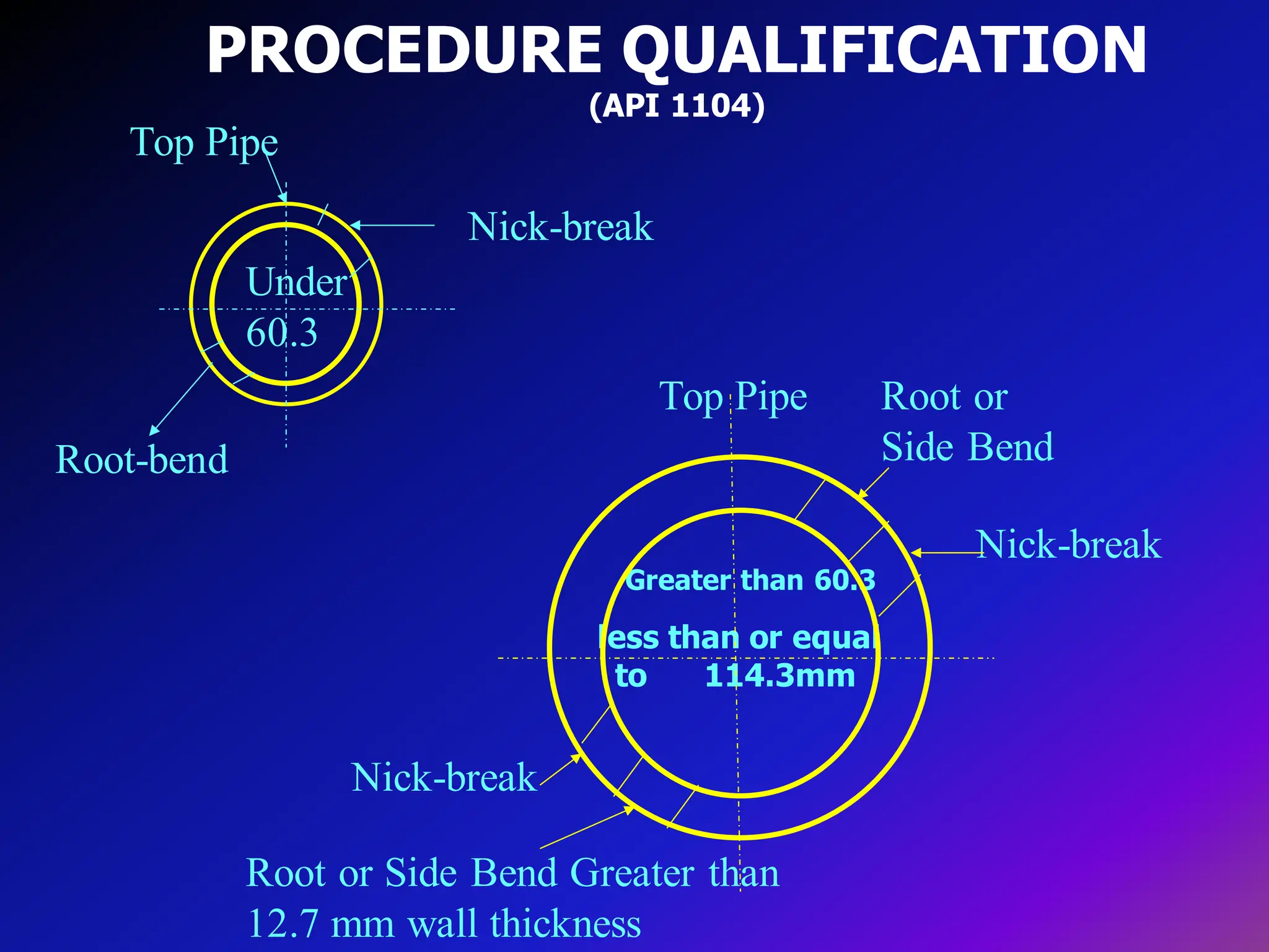
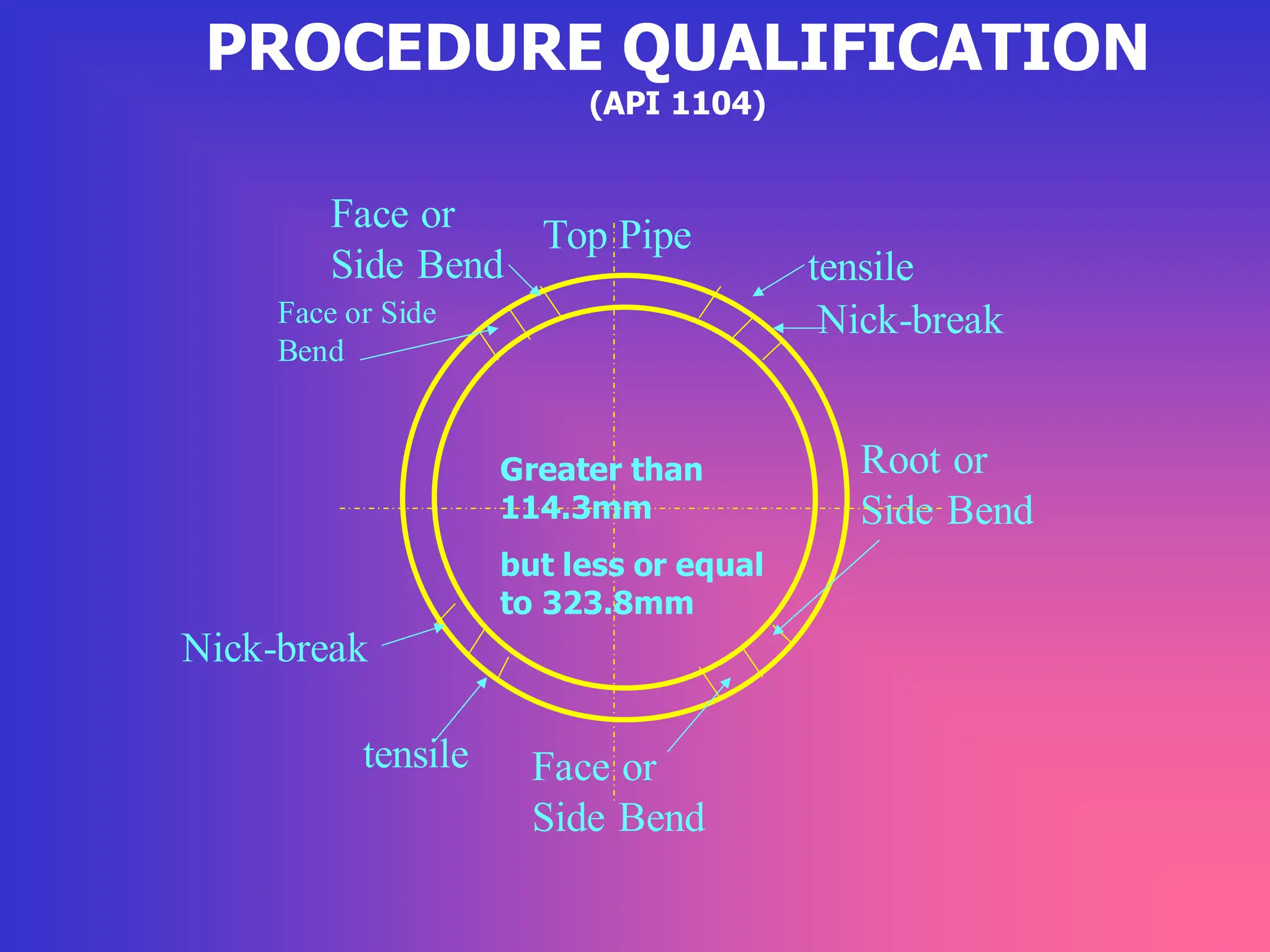
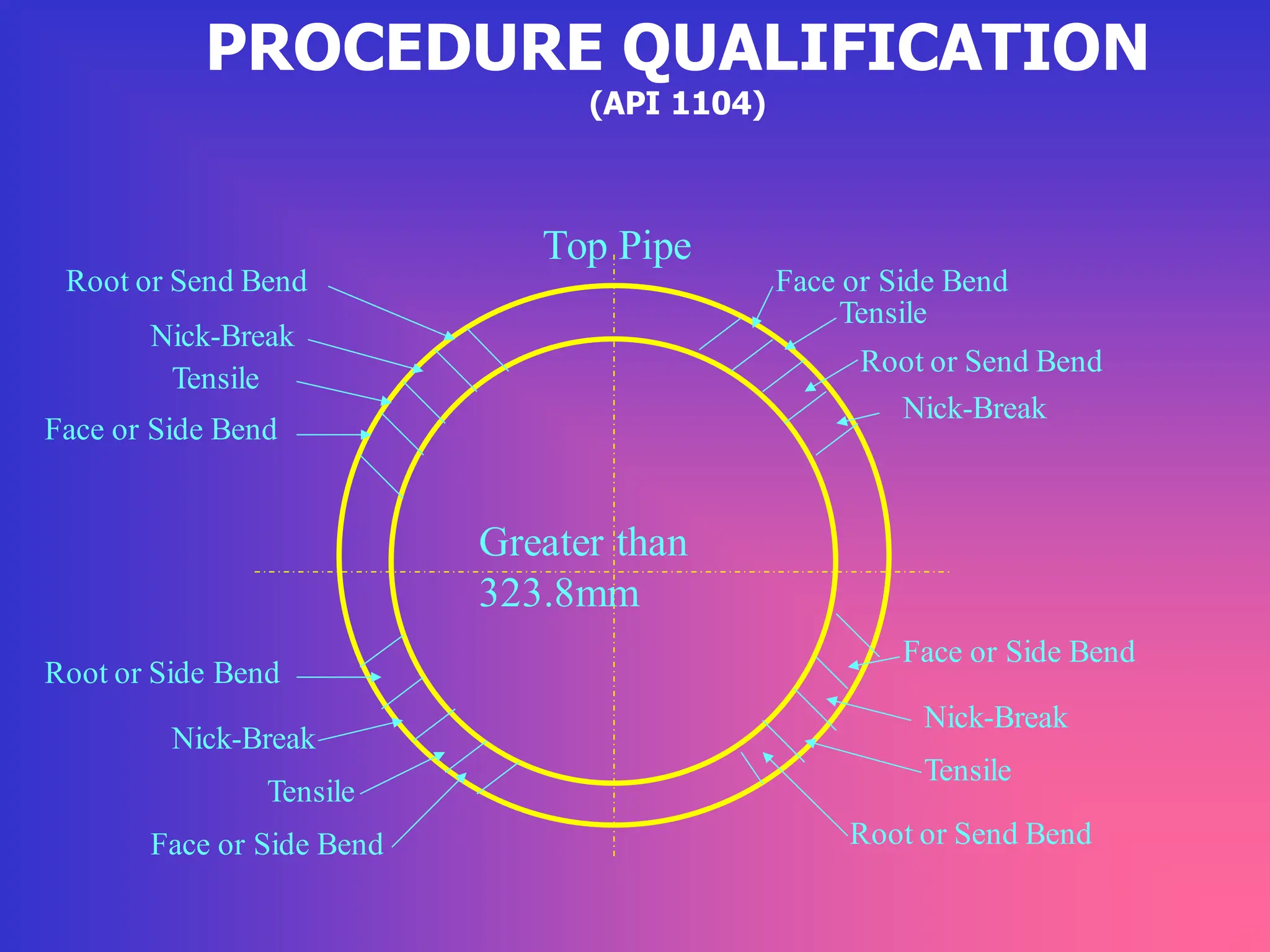
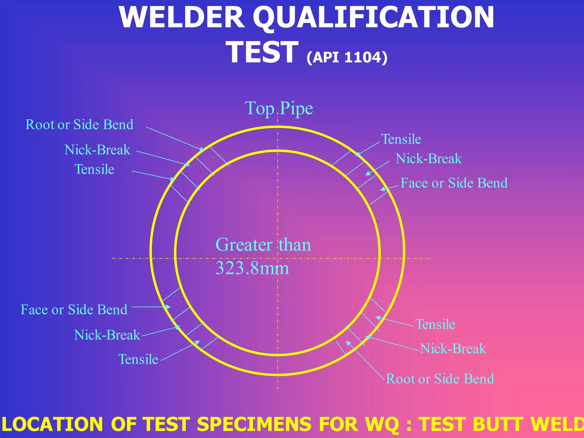
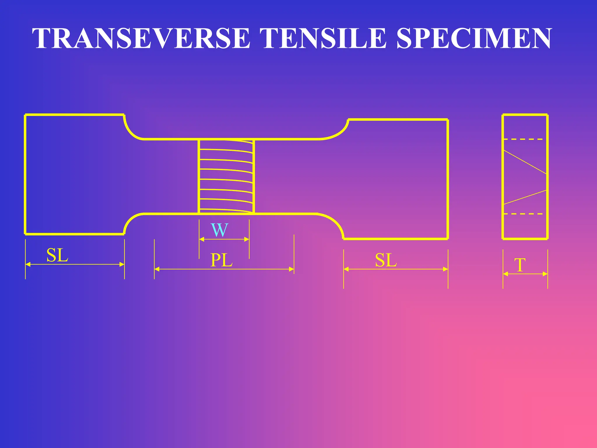
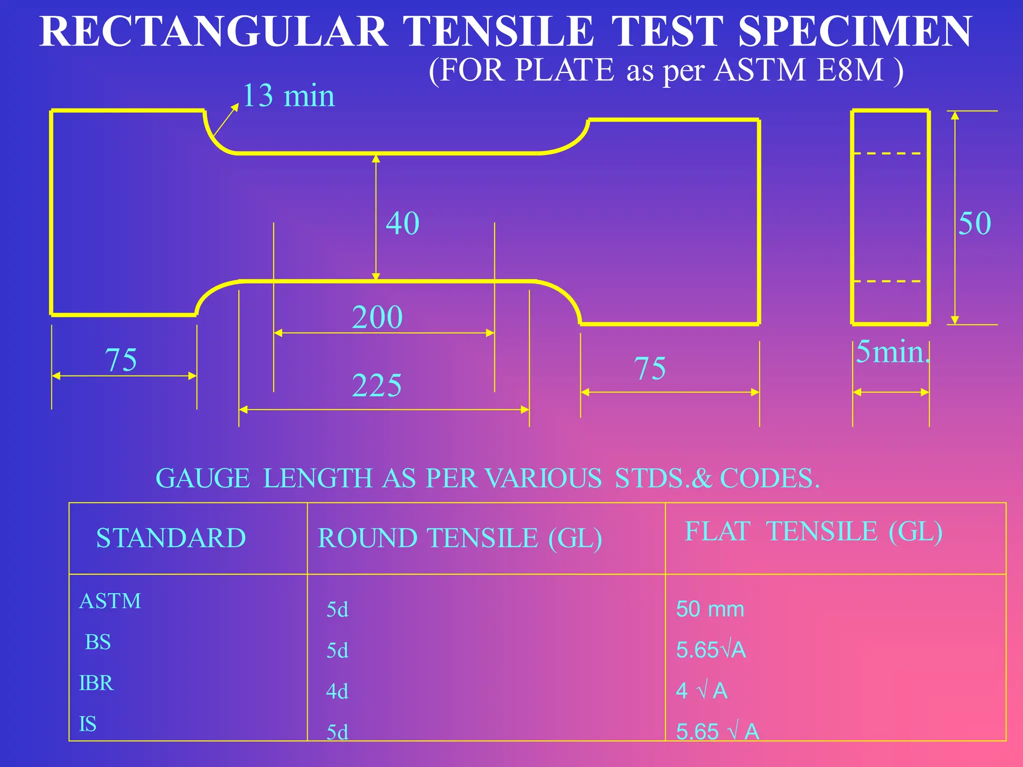
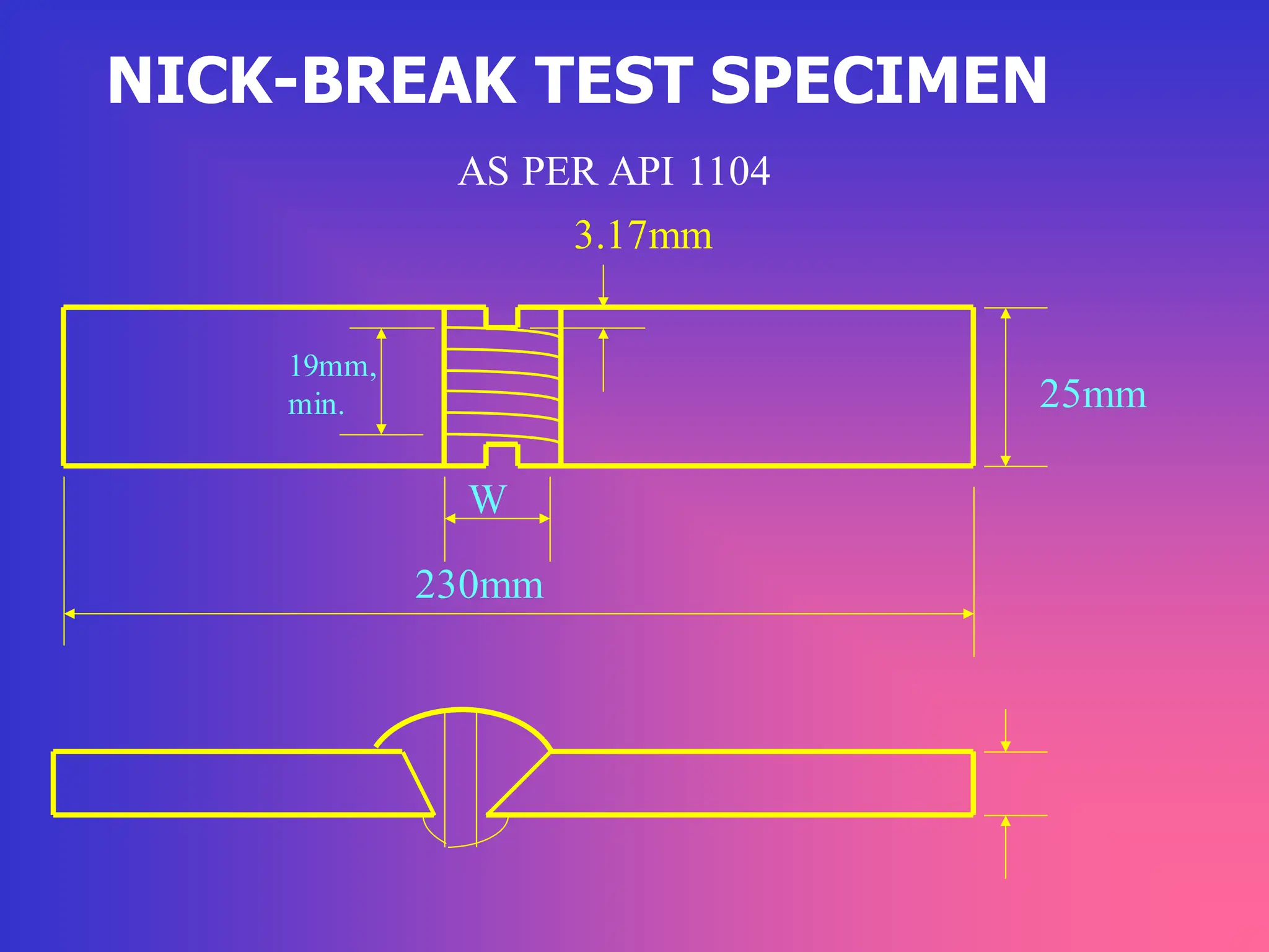
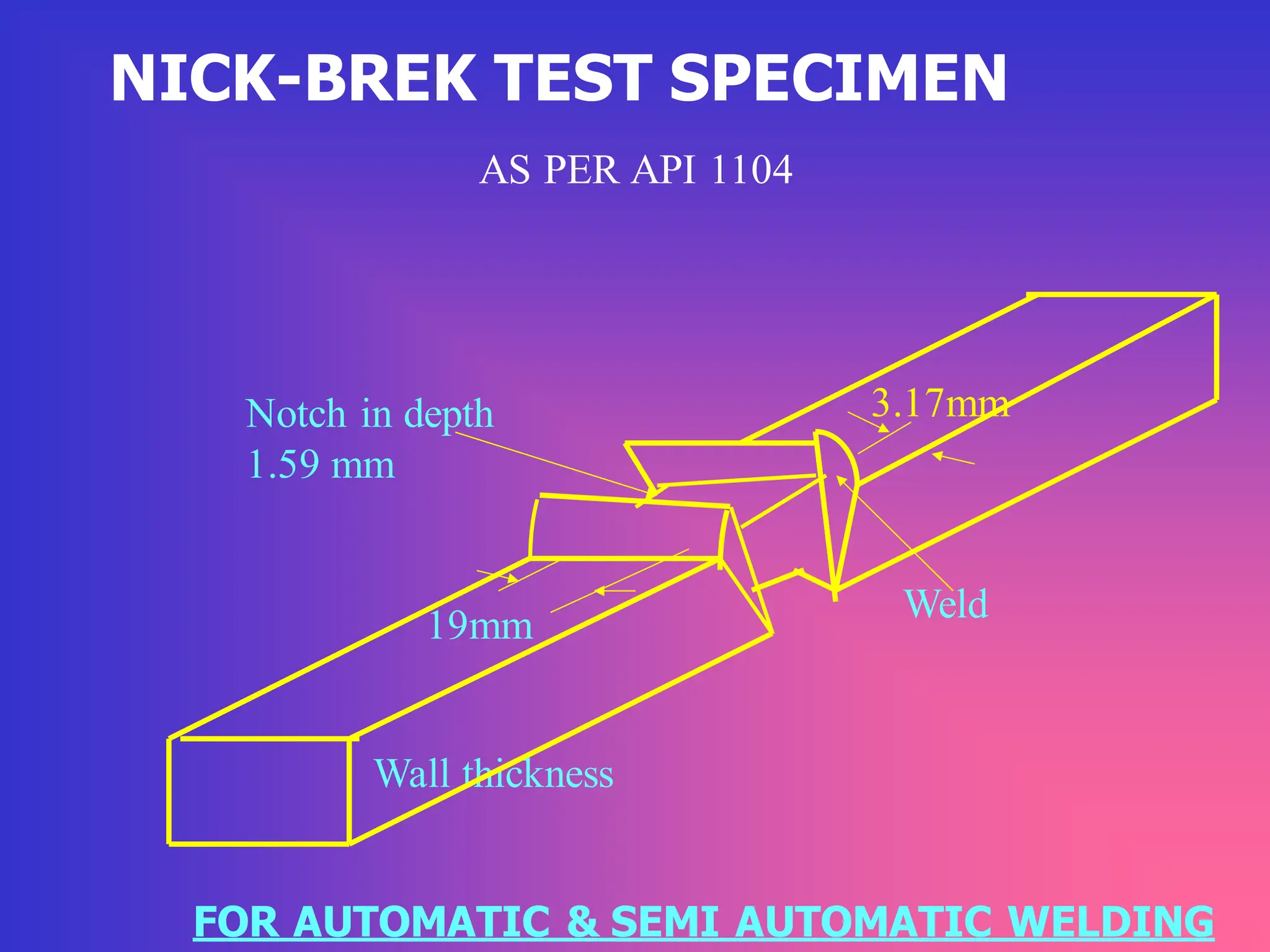
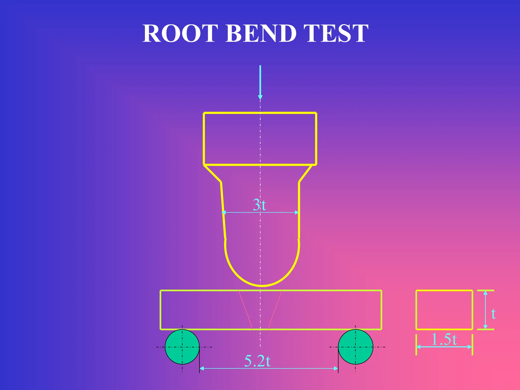
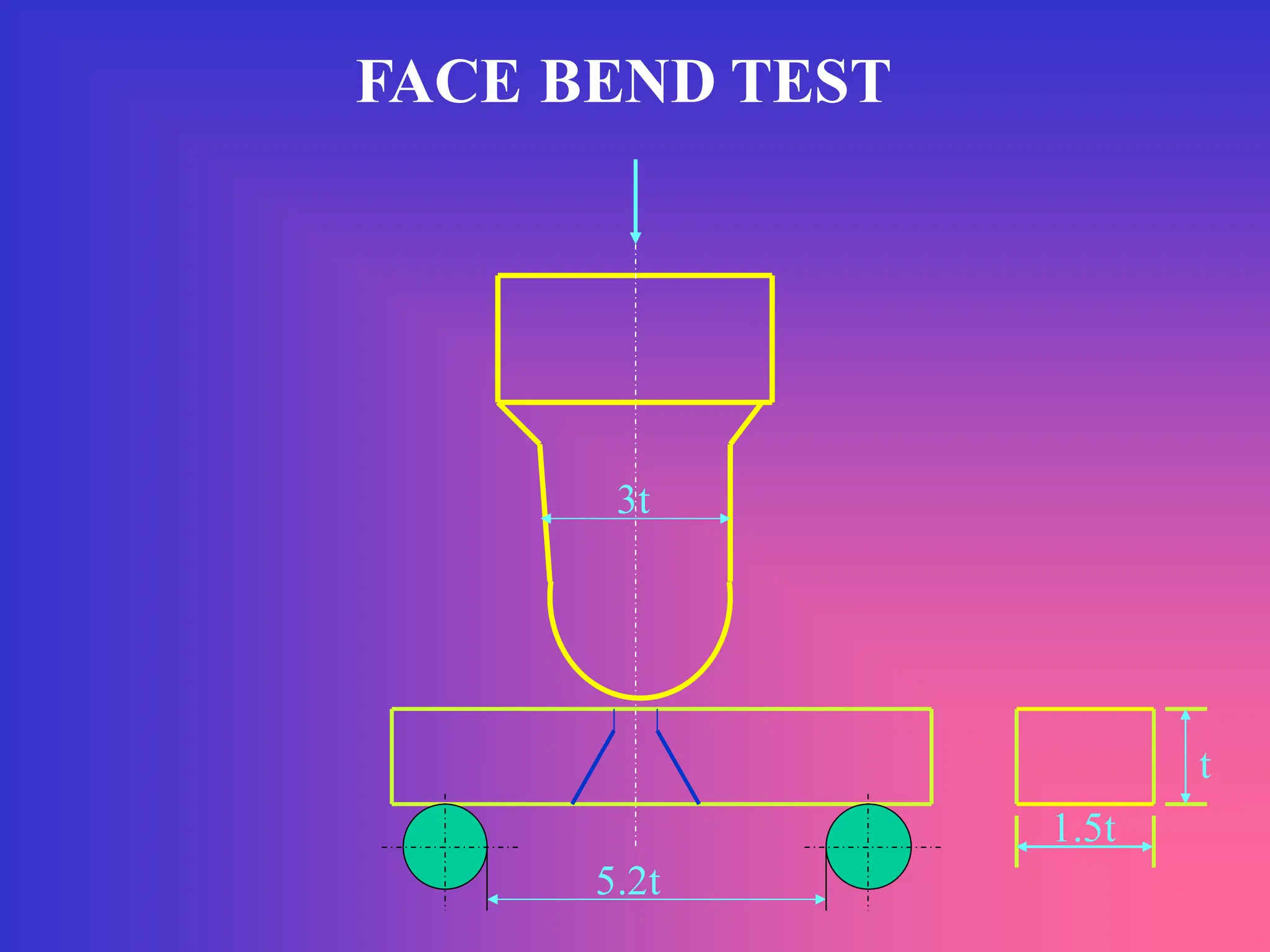
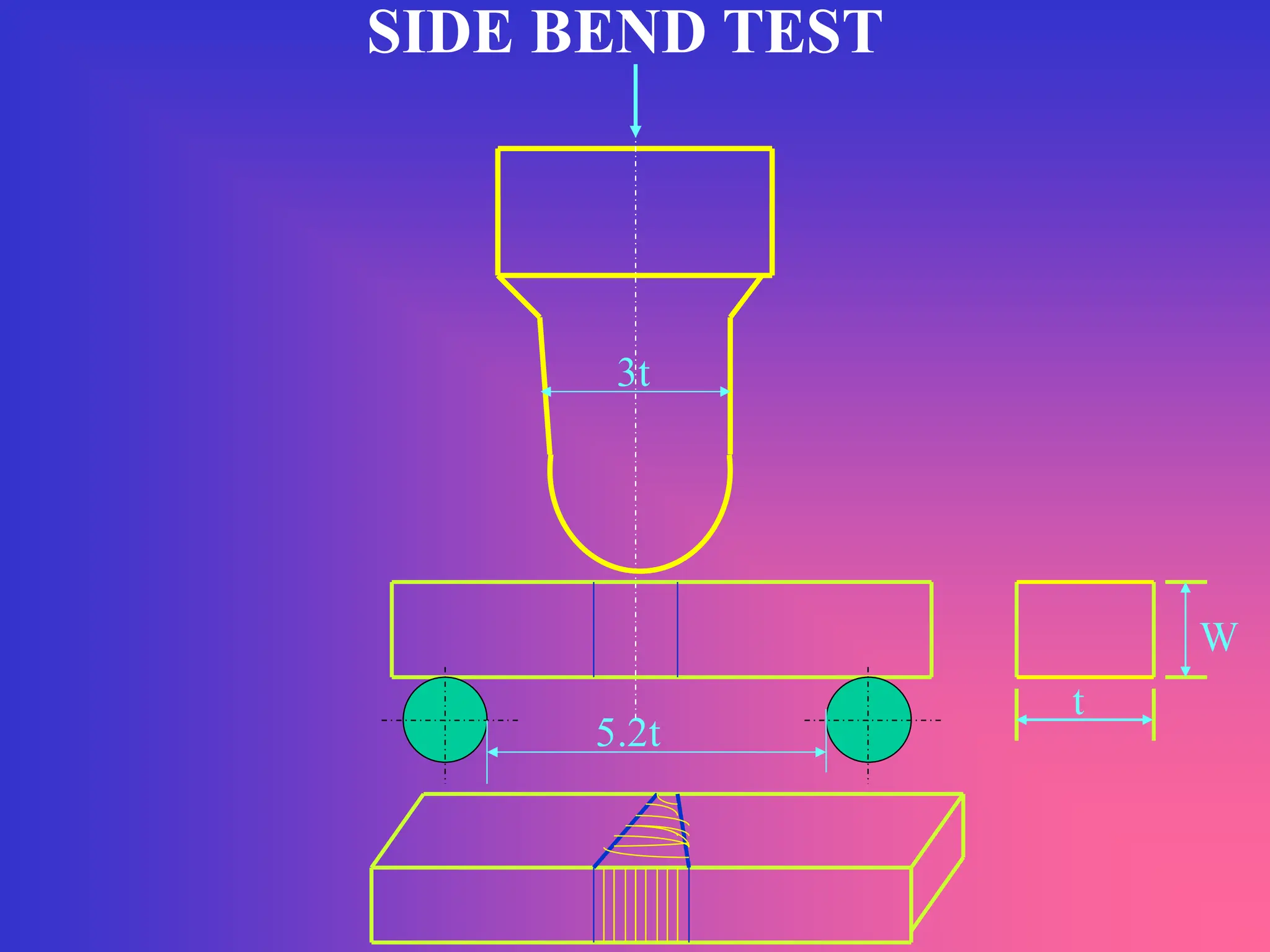
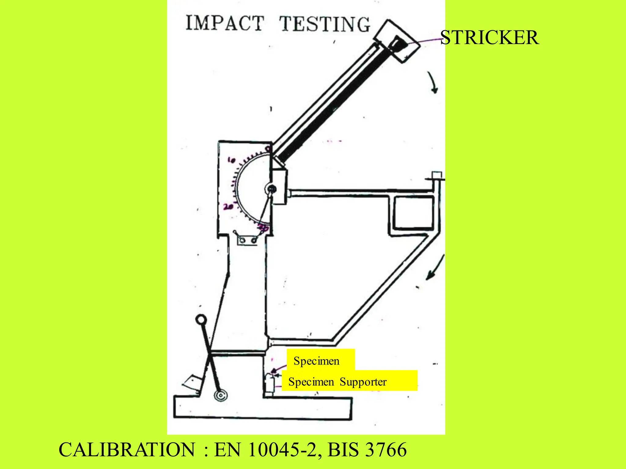
DESTRUCTIVE TESTING
MECHANICAL METALLOGRAPHIC CHEMICAL
TESTING EXAMINATION ANALYSIS
1. TENSILE 1. MACRO 1. WET ANALYSIS
2. BEND 2. MICRO 2. DRY ANALYSIS
3. IMPACT 3. X-RAY -
4. HARDNESS FLORESCENCE
5. DROP WEIGHT 4. ATOMIC-
6. DROP WEIGHT TEAR ABSORPTION
7. NICK BREAK
8. FATIGUE
9. CREEP
PURPOSE OF TESTING
1. To determine the fundamental properties.
2. To determine Mechanical, Chemical and
Metallurgical properties in order to find out the
suitability for a specific purpose.
3. To record the data for a group of metals and alloys
for the purpose of design.
4. To check weather heat treatment imparted has
been carried out satisfactorily.
5. To investigate into defects and flaws of the material
so as to improve manufacturing techniques.
PURPOSE OF TESTING
II. As for as welding is concerned
1. Qualification of welding procedure.
2. Qualification of welding and welding operation.
3. Qualification of welding consumables.
4. Quality control
STANDARD TEST METODS
(For Mechanical Testing)
TYPE ASTM BS IS
Tensile E8 EN10002-1 1608,1521
Bend E190 EN287-1 1599
Impact E23 EN 10045-2 1757
Hardness E10(Brinell) BS 240-1 1500
E18(Rockwell) BS 891-1 1586
E 92(Vickers) BS 427 1501
STANDARDS & CODES FOR DESTRUCTIVE
TESTING
ASTM-A370 : Mechanical Testing of Steels
AWS-B4 : Standard methods for Mechanical testing of welds
BS-709 : Destructive testing for fusion welded Boiler
drums.
IBR Ch.-V : Fusion Welded Boiler Drums.
IBR Ch.-xiii : Qualification test for Welders.
IBR Ch.-XII : Shell type Boiler construction
AWS 5.1,5.4,5.5 : Electrode Qualification Tests
IS 814,5206,1395 : Electrode Qualification Tests
ASME Sec.IX : Procedure & performance Qualification of welding
API-5L : For seamless and welded steel tubes & pipes.
TEST PLATE FOR PERFORMANCE
QUALIFICATION (as per IBR)
B
250 mm
406 mm
B1 T1 B2
M
m
B1
T2 B2
16
mm
weld
TEST PIPE & TUBE FOR PERFORMANCE
QUALIFICATION (as per IBR
Face
Face
Root
Macro
Macro
250mm
Root
PIPE Ø127x12.5mm, CS Tube Ø63.5x5.2mm, AS Tube Ø54x5mm
weld
PROCEDURE QUALIFICATION
(ASME SEC. IX)
QW-463.1(a) : Less than 3/4” PLATES
300mm
250mm
Discard Discard
Reduced Sec. Tensile Specimen
Root Bend
Face Bend
Root Bend
Face Bend
Tensile Specimen
Discard Discard
Reduced Sec.
PROCEDURE QUALIFICATION
(ASME SEC. IX)
QW-463 1(b) :Over 3/4” PLATES
300
Discard Discard
Discard Discard
Reduced Sec.
Side
Side
Side
Side
Bend
Bend
Bend
Bend
Tensile Specimen
250
Reduced Sec. Tensile Specimen
WELDER QUALIFICATION TEST
(API 1104)
Grater than 60.3
less than or equal to
114.3mm
Top Pipe
Under
60.3
Nick-break
Root-bend
Top Pipe Root or
Side Bend
Nick-break
Root or Side Bend Greater than
12.7 mm wall thickness
Nick-break
WELDER QUALIFICATION
TEST (API 1104)
Nick-break
Nick-break
Root or
Side Bend
Face or Side
Bend
Greater than
114.3mm
but less or equal
to 323.8mm
Top Pipe
tensile
Face or
Side Bend
Root or
Side Bend
PROCEDURE QUALIFICATION
(API 1104)
Greater than 60.3
less than or equal
to 114.3mm
Top Pipe
Under
60.3
Nick-break
Root-bend
Top Pipe Root or
Side Bend
Nick-break
Root or Side Bend Greater than
12.7 mm wall thickness
Nick-break
PROCEDURE QUALIFICATION
(API 1104)
Nick-break
Nick-break
Root or
Side Bend
Face or Side
Bend
Greater than
114.3mm
but less or equal
to 323.8mm
Top Pipe
tensile
tensile
Face or
Side Bend
Face or
Side Bend
PROCEDURE QUALIFICATION
(API 1104)
Tensile
Root or Send Bend
Nick-Break
Top Pipe
Greater than
323.8mm
Face or Side Bend
Face or Side Bend
Nick-Break
Tensile
Root or Send Bend
Face or Side Bend
Tensile
Nick-Break
Root or Side Bend
Root or Send Bend
Nick-Break
Tensile
Face or Side Bend
WELDER QUALIFICATION
TEST (API 1104)
Tensile
Face or Side Bend
Nick-Break
Top Pipe
Greater than
323.8mm
Nick-Break
Tensile
Root or Side Bend
Face or Side Bend
Tensile
Nick-Break
Root or Side Bend
Nick-Break
Tensile
LOCATION OF TEST SPECIMENS FOR WQ : TEST BUTT WELD
TENSILE SPECIMENS
TRANSEVERSE
TENSILE
ALL WELD
TENSILE
ELECTRODE QUALIFICATION TEST(AS PERAWS)
WELD
ALL WELD TENSILE
170mm min. (1No.)
25
25
15 IMPACT SPECIMEN
(5Nos.)
DISCARD
DISCARD
ALL WELD TENSILE SPECIMEN (as per IS)
R5
FOR SIZE 3.15 mm and BELOW
FOR SIZE 4mm AND ABOVE
G L 50
10±0.09
PL 60
12 min
70mm min
6.4 ±0.075
GL 32
44.8
38.9
9.5
THE SURFACE FINISH WIT THE PL SHALL BE 1.6
ALL WELD TENSILE SPECIMEN (AWS)
THE SURFACE FINISH WITH THE PL SHALL BE 1.6
R 9.5
SIZE OF ELECTRODE 3.15 mm and BELOW
Ø12.7±0.25
GL 50.8 ±0.13
PL 57.1
Ø19.1
R 4.6
GL 25.4 ±0.13
GL 31.8
Ø 9.5
SL
SL
SL
SL
SIZE OF ELCTRODE 4 mm and ABOVE
Ø6.4±0.13
UNIVERSAL TESTING MACHINE
CALIBRATION:
ASTM-E4,
BIS: 1828,
EN: 10002-2
CALIBRATION : EN 10045-2, BIS 3766
0.
TRANSEVERSE TENSILE SPECIMEN
W
PL
SL SL T
RECTANGULAR TENSILE TEST SPECIMEN
200
225
75
75
13 min
(FOR PLATE as per ASTM E8M )
ASTM
BS
IBR
IS
50 mm
5.65A
4  A
5.65  A
5min.
50
STANDARD ROUND TENSILE (GL) FLAT TENSILE (GL)
5d
5d
4d
5d
GAUGE LENGTH AS PER VARIOUS STDS.& CODES.
40
W
230mm
25mm
AS PER API 1104
3.17mm
19mm,
min.
NICK-BREAK TEST SPECIMEN
NICK-BREK TEST SPECIMEN
AS PER API 1104
3.17mm
Wall thickness
19mm
Notch in depth
1.59 mm
FOR AUTOMATIC & SEMI AUTOMATIC WELDING
Weld
REQUIREMENTS :
1. Specimen shall show complete penetration and
fusion
2. Any gas pocket shall not exceed1/16” (1.59mm)
3. Combined area of all gas pockets shall not exceed
2% of exposed surface
4. Slag inclusion shall not be more than 3.17mm or one
half the wall thickness in length, whichever is smaller
5. There shall be 12.7mm of sound weld metal between
adjacent slag inclusions
BEND TEST METHODS
1. Guided bend
2. Free Bend
ROOT BEND TEST
t
BEND SAMPLE OF 40 mm THICK PLATE
IN COLD WIRE ADDITION SAW
ROOT BEND TEST
t
5.2t
1.5t
3t
FACE BEND TEST
t
5.2t
1.5t
3t
SIDE BEND TEST
W
5.2t
t
3t
Specimen Supporter
Specimen
CALIBRATION : EN 10045-2, BIS 3766
STRICKER
TENIUS OLSON IMPACT TESTER
CAL : ASTM - E23
IMPACT TEST SPECIMEN
10±0.025
55±0.1
27.5
10 ±0.025
45°±0.1°
2±0.1
55±0.1
27.5
10 ±0.025
5±0.1
2
CHARPY ‘V’NOTCH TEST SPECIMEN
CHARPY ‘U’NOTCH TEST SPECIMEN
10±0.025
IZOD IMPACT TEST SPECIMEN
75 27.5 10
10
2
IMPACT TEST SPECIMEN
AS API 5L (SR 5.3)
Min. 28 mm
Max.13.5 mm Max.13.5 mm
T
IMPACT SPECIMENS WITH TAPERED END
HARDNESS TEST
1.BRINELL HARDNESS 2. ROCKWELL HARDNESS
3.VICKERS HARDNESS 4. MICRO HARDNESS
BRINELL HARDNESS TEST
•HARDENED STEEL BALL IS USED FOR
MEASURING UPTO 500 BHN
•FOR 500 BHN TUNGSTON STEEL BALL IS USED F
• FOR IRON AND STEEL 3000Kg OF LOAD IS APPLIED
•FOR INTERMEDIATE HARD MATERIALS 1500Kg, 500Kg
OF LOADS ARE USED.
•FOR SOFT MATERIALS 100 Kg OF WEIGHT IS USED.
•RATE OF LOADING IS AN IMPORTANT CRITERIA,
RAPID RATE OF LOADING AFECTS THE INDENTATION.
BHN=APPLIED LOAD/AREA OF INDENTATION
BHN=P/[( D/2) X (D- D2 - d2)]
WHERE P=LOAD IN Kg,
D=DIAMETER OF STEEL BALL IN mm, d= DIAMETER OF THE INDENTATION IN mm.
APPLICATION
FOR C.STEEL, CAST IRON,COPPERALLOYS, ALUMINIUM ALLOYS, LEAD AND TIN ETC.
POLISHED SURFACE
UNIVERSAL HARDNESS TESTER
TEST IS CARRIED OUT BY IN ACCORDENCE
ASTM E92 TEST IS CARRID OUT BY IN
ACCORDENCE ASTM E92
Minor Load Major Load
ROCKWELL HARDNESS TEST
TEST IS CARRIED OUT BY IN ACCORDENCE
ASTM E92 TEST IS CARRID OUT BY IN
ACCORDENCE ASTM E92
VICKERS HARDNESS TEST
Angle between faces of the
pyramid is 136°
VHN=1.854 P/ D2
P=Load in Kgf
D= Average of measured
diagonalsof impression in mm
TEST IS CARRIED OUT BY IN ACCORDENCE WITH ASTM E92
DROP WEIGHT TEST
STANDARD DROP WEIGHT TEST SPECIMEN
P1=25X90X360
P2=19X50X130
P3=16X50X130
DROP WEIGHT TEST
DROP WEIGHT TEST IS CONDUCTED IN ACCORDANCE WITH ASTM E208
SPECIMEN
SPECIMEN
SUPPORTER
MACRO EXAMINATION
It involves the visual observation of the gross structural
details of materials after preparation of the surface,
either by unaided or with the aid of low power
microscope . Usually under 10X.
When macroscopic examinations appropriately carried
out, some important metallic characteristics are
determined by such studies.
Example : As for as welding is concerned macro will
reveal
Undercut, Excess penetration, Incomplete penetration,
Dilution lack of fusion pores and cracks etc.
DC: 700A,30V/AC: 600A,32 V,0.5m/min
MACRO STRUCTURE OF BEAD IN COLD
WIRE ADDITION SAW
MACRO STRUCTURE OF 25mm THICK
WELD PLATE
MACRO STRUCTURE OF 40 mm THICK
SAW PLATE
MICRO EXAMINATION
The most important part of metallography deals with the
microscopic examinations of a prepared metal
specimen,employing magnification with the optical
microscope from 100X to as high as 2000X.
Such microscopic studies are of much broader scope than
macro examinations.
It will reveal clear picture of structural characteristics as
grain size, shape, distribution secondary phases, non
metallic inclusions, segregation and other heterogeneous
conditions.
Microstructure reflects almost complete history of the
mechanical and thermal treatment that a metal has
received.
MICROSTRUCTURE : F + P
200x
MICRO STRUCTURE OF BASE METAL
MICRO STRUCTURE OF SAW
WELD METAL
MICRO STRUCTURE OF HAZ IN SAW
MICRO PHOTOGRAPH AT THE CRACK
ORIGIN (200 x)
THANK YOU

Destructive_Testing_overview_1717035747.pdf

  • 1.
    DESTRUCTIVE TESTING MECHANICAL METALLOGRAPHICCHEMICAL TESTING EXAMINATION ANALYSIS 1. TENSILE 1. MACRO 1. WET ANALYSIS 2. BEND 2. MICRO 2. DRY ANALYSIS 3. IMPACT 3. X-RAY - 4. HARDNESS FLORESCENCE 5. DROP WEIGHT 4. ATOMIC- 6. DROP WEIGHT TEAR ABSORPTION 7. NICK BREAK 8. FATIGUE 9. CREEP
  • 2.
    PURPOSE OF TESTING 1.To determine the fundamental properties. 2. To determine Mechanical, Chemical and Metallurgical properties in order to find out the suitability for a specific purpose. 3. To record the data for a group of metals and alloys for the purpose of design. 4. To check weather heat treatment imparted has been carried out satisfactorily. 5. To investigate into defects and flaws of the material so as to improve manufacturing techniques.
  • 3.
    PURPOSE OF TESTING II.As for as welding is concerned 1. Qualification of welding procedure. 2. Qualification of welding and welding operation. 3. Qualification of welding consumables. 4. Quality control
  • 4.
    STANDARD TEST METODS (ForMechanical Testing) TYPE ASTM BS IS Tensile E8 EN10002-1 1608,1521 Bend E190 EN287-1 1599 Impact E23 EN 10045-2 1757 Hardness E10(Brinell) BS 240-1 1500 E18(Rockwell) BS 891-1 1586 E 92(Vickers) BS 427 1501
  • 5.
    STANDARDS & CODESFOR DESTRUCTIVE TESTING ASTM-A370 : Mechanical Testing of Steels AWS-B4 : Standard methods for Mechanical testing of welds BS-709 : Destructive testing for fusion welded Boiler drums. IBR Ch.-V : Fusion Welded Boiler Drums. IBR Ch.-xiii : Qualification test for Welders. IBR Ch.-XII : Shell type Boiler construction AWS 5.1,5.4,5.5 : Electrode Qualification Tests IS 814,5206,1395 : Electrode Qualification Tests ASME Sec.IX : Procedure & performance Qualification of welding API-5L : For seamless and welded steel tubes & pipes.
  • 6.
    TEST PLATE FORPERFORMANCE QUALIFICATION (as per IBR) B 250 mm 406 mm B1 T1 B2 M m B1 T2 B2 16 mm weld
  • 7.
    TEST PIPE &TUBE FOR PERFORMANCE QUALIFICATION (as per IBR Face Face Root Macro Macro 250mm Root PIPE Ø127x12.5mm, CS Tube Ø63.5x5.2mm, AS Tube Ø54x5mm weld
  • 8.
    PROCEDURE QUALIFICATION (ASME SEC.IX) QW-463.1(a) : Less than 3/4” PLATES 300mm 250mm Discard Discard Reduced Sec. Tensile Specimen Root Bend Face Bend Root Bend Face Bend Tensile Specimen Discard Discard Reduced Sec.
  • 9.
    PROCEDURE QUALIFICATION (ASME SEC.IX) QW-463 1(b) :Over 3/4” PLATES 300 Discard Discard Discard Discard Reduced Sec. Side Side Side Side Bend Bend Bend Bend Tensile Specimen 250 Reduced Sec. Tensile Specimen
  • 10.
    WELDER QUALIFICATION TEST (API1104) Grater than 60.3 less than or equal to 114.3mm Top Pipe Under 60.3 Nick-break Root-bend Top Pipe Root or Side Bend Nick-break Root or Side Bend Greater than 12.7 mm wall thickness Nick-break
  • 11.
    WELDER QUALIFICATION TEST (API1104) Nick-break Nick-break Root or Side Bend Face or Side Bend Greater than 114.3mm but less or equal to 323.8mm Top Pipe tensile Face or Side Bend Root or Side Bend
  • 12.
    PROCEDURE QUALIFICATION (API 1104) Greaterthan 60.3 less than or equal to 114.3mm Top Pipe Under 60.3 Nick-break Root-bend Top Pipe Root or Side Bend Nick-break Root or Side Bend Greater than 12.7 mm wall thickness Nick-break
  • 13.
    PROCEDURE QUALIFICATION (API 1104) Nick-break Nick-break Rootor Side Bend Face or Side Bend Greater than 114.3mm but less or equal to 323.8mm Top Pipe tensile tensile Face or Side Bend Face or Side Bend
  • 14.
    PROCEDURE QUALIFICATION (API 1104) Tensile Rootor Send Bend Nick-Break Top Pipe Greater than 323.8mm Face or Side Bend Face or Side Bend Nick-Break Tensile Root or Send Bend Face or Side Bend Tensile Nick-Break Root or Side Bend Root or Send Bend Nick-Break Tensile Face or Side Bend
  • 15.
    WELDER QUALIFICATION TEST (API1104) Tensile Face or Side Bend Nick-Break Top Pipe Greater than 323.8mm Nick-Break Tensile Root or Side Bend Face or Side Bend Tensile Nick-Break Root or Side Bend Nick-Break Tensile LOCATION OF TEST SPECIMENS FOR WQ : TEST BUTT WELD
  • 16.
  • 17.
    ELECTRODE QUALIFICATION TEST(ASPERAWS) WELD ALL WELD TENSILE 170mm min. (1No.) 25 25 15 IMPACT SPECIMEN (5Nos.) DISCARD DISCARD
  • 18.
    ALL WELD TENSILESPECIMEN (as per IS) R5 FOR SIZE 3.15 mm and BELOW FOR SIZE 4mm AND ABOVE G L 50 10±0.09 PL 60 12 min 70mm min 6.4 ±0.075 GL 32 44.8 38.9 9.5 THE SURFACE FINISH WIT THE PL SHALL BE 1.6
  • 19.
    ALL WELD TENSILESPECIMEN (AWS) THE SURFACE FINISH WITH THE PL SHALL BE 1.6 R 9.5 SIZE OF ELECTRODE 3.15 mm and BELOW Ø12.7±0.25 GL 50.8 ±0.13 PL 57.1 Ø19.1 R 4.6 GL 25.4 ±0.13 GL 31.8 Ø 9.5 SL SL SL SL SIZE OF ELCTRODE 4 mm and ABOVE Ø6.4±0.13
  • 20.
  • 21.
    CALIBRATION : EN10045-2, BIS 3766
  • 23.
  • 24.
  • 25.
    RECTANGULAR TENSILE TESTSPECIMEN 200 225 75 75 13 min (FOR PLATE as per ASTM E8M ) ASTM BS IBR IS 50 mm 5.65A 4  A 5.65  A 5min. 50 STANDARD ROUND TENSILE (GL) FLAT TENSILE (GL) 5d 5d 4d 5d GAUGE LENGTH AS PER VARIOUS STDS.& CODES. 40
  • 26.
    W 230mm 25mm AS PER API1104 3.17mm 19mm, min. NICK-BREAK TEST SPECIMEN
  • 27.
    NICK-BREK TEST SPECIMEN ASPER API 1104 3.17mm Wall thickness 19mm Notch in depth 1.59 mm FOR AUTOMATIC & SEMI AUTOMATIC WELDING Weld
  • 28.
    REQUIREMENTS : 1. Specimenshall show complete penetration and fusion 2. Any gas pocket shall not exceed1/16” (1.59mm) 3. Combined area of all gas pockets shall not exceed 2% of exposed surface 4. Slag inclusion shall not be more than 3.17mm or one half the wall thickness in length, whichever is smaller 5. There shall be 12.7mm of sound weld metal between adjacent slag inclusions
  • 29.
    BEND TEST METHODS 1.Guided bend 2. Free Bend
  • 30.
  • 31.
    BEND SAMPLE OF40 mm THICK PLATE IN COLD WIRE ADDITION SAW
  • 32.
  • 33.
  • 34.
  • 35.
    Specimen Supporter Specimen CALIBRATION :EN 10045-2, BIS 3766 STRICKER
  • 36.
    TENIUS OLSON IMPACTTESTER CAL : ASTM - E23
  • 37.
    IMPACT TEST SPECIMEN 10±0.025 55±0.1 27.5 10±0.025 45°±0.1° 2±0.1 55±0.1 27.5 10 ±0.025 5±0.1 2 CHARPY ‘V’NOTCH TEST SPECIMEN CHARPY ‘U’NOTCH TEST SPECIMEN 10±0.025
  • 38.
    IZOD IMPACT TESTSPECIMEN 75 27.5 10 10 2
  • 39.
    IMPACT TEST SPECIMEN ASAPI 5L (SR 5.3) Min. 28 mm Max.13.5 mm Max.13.5 mm T IMPACT SPECIMENS WITH TAPERED END
  • 40.
    HARDNESS TEST 1.BRINELL HARDNESS2. ROCKWELL HARDNESS 3.VICKERS HARDNESS 4. MICRO HARDNESS BRINELL HARDNESS TEST •HARDENED STEEL BALL IS USED FOR MEASURING UPTO 500 BHN •FOR 500 BHN TUNGSTON STEEL BALL IS USED F • FOR IRON AND STEEL 3000Kg OF LOAD IS APPLIED •FOR INTERMEDIATE HARD MATERIALS 1500Kg, 500Kg OF LOADS ARE USED. •FOR SOFT MATERIALS 100 Kg OF WEIGHT IS USED. •RATE OF LOADING IS AN IMPORTANT CRITERIA, RAPID RATE OF LOADING AFECTS THE INDENTATION.
  • 41.
    BHN=APPLIED LOAD/AREA OFINDENTATION BHN=P/[( D/2) X (D- D2 - d2)] WHERE P=LOAD IN Kg, D=DIAMETER OF STEEL BALL IN mm, d= DIAMETER OF THE INDENTATION IN mm. APPLICATION FOR C.STEEL, CAST IRON,COPPERALLOYS, ALUMINIUM ALLOYS, LEAD AND TIN ETC. POLISHED SURFACE
  • 42.
    UNIVERSAL HARDNESS TESTER TESTIS CARRIED OUT BY IN ACCORDENCE ASTM E92 TEST IS CARRID OUT BY IN ACCORDENCE ASTM E92
  • 43.
    Minor Load MajorLoad ROCKWELL HARDNESS TEST TEST IS CARRIED OUT BY IN ACCORDENCE ASTM E92 TEST IS CARRID OUT BY IN ACCORDENCE ASTM E92
  • 44.
  • 45.
    VICKERS HARDNESS TEST Anglebetween faces of the pyramid is 136° VHN=1.854 P/ D2 P=Load in Kgf D= Average of measured diagonalsof impression in mm TEST IS CARRIED OUT BY IN ACCORDENCE WITH ASTM E92
  • 47.
    DROP WEIGHT TEST STANDARDDROP WEIGHT TEST SPECIMEN P1=25X90X360 P2=19X50X130 P3=16X50X130
  • 48.
    DROP WEIGHT TEST DROPWEIGHT TEST IS CONDUCTED IN ACCORDANCE WITH ASTM E208 SPECIMEN SPECIMEN SUPPORTER
  • 49.
    MACRO EXAMINATION It involvesthe visual observation of the gross structural details of materials after preparation of the surface, either by unaided or with the aid of low power microscope . Usually under 10X. When macroscopic examinations appropriately carried out, some important metallic characteristics are determined by such studies. Example : As for as welding is concerned macro will reveal Undercut, Excess penetration, Incomplete penetration, Dilution lack of fusion pores and cracks etc.
  • 50.
    DC: 700A,30V/AC: 600A,32V,0.5m/min MACRO STRUCTURE OF BEAD IN COLD WIRE ADDITION SAW
  • 51.
    MACRO STRUCTURE OF25mm THICK WELD PLATE
  • 52.
    MACRO STRUCTURE OF40 mm THICK SAW PLATE
  • 53.
    MICRO EXAMINATION The mostimportant part of metallography deals with the microscopic examinations of a prepared metal specimen,employing magnification with the optical microscope from 100X to as high as 2000X. Such microscopic studies are of much broader scope than macro examinations. It will reveal clear picture of structural characteristics as grain size, shape, distribution secondary phases, non metallic inclusions, segregation and other heterogeneous conditions. Microstructure reflects almost complete history of the mechanical and thermal treatment that a metal has received.
  • 54.
  • 55.
  • 56.
    MICRO STRUCTURE OFSAW WELD METAL
  • 57.
  • 58.
    MICRO PHOTOGRAPH ATTHE CRACK ORIGIN (200 x)
  • 59.