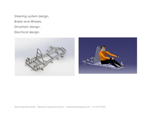
This design portfolio cover some of my work with CATIA V5, Creo Parametric 3.0 and AutoCAD. I am seeking for an opportunity as a Mechanical Design Engineer. The contact details are provided in the end slide of the portfolio.
THANK YOU
This design portfolio cover some of my work with CATIA V5, Creo Parametric 3.0 and AutoCAD. I am seeking for an opportunity as a Mechanical Design Engineer. The contact details are provided in the end slide of the portfolio.
THANK YOU
This is a portfolio of my engineering design work. It is meant as a visual complement to my LinkedIn profile, and provides a snapshot of some of my past projects.
This is my design portfolio and it is my hope that this will allow you to better assess how my skills can be applied to your company.
I would be happy to talk in more detail and can be reached on Email:ibrahim_dilawer@yahoo.com or phone:+44(0)755-027-9908
CADMAXX solutions is the ISO 9001:2008, Certified CAD/CAM/CAE Training Centre, We offered High end Courses are Solidworks, AutoCAD, Catia, UG NX, Pro E, Hypermesn, In Bangalore, Gulbarga, Raichur...
Contact us @ 9739866634
www.cadmaxx.com
Mail: digitalm@cadmaxx.com
CATIA is an acronym for Computer Aided Three-Dimensional Interactive Application. It is the most proficient, powerful and highly popular CAD i.e. computer aided design software. It is created, developed and owned by Dassault Systemes of France.
Senior CAE Engineer with 2 years of experience in Automotive Crash & Safety, NVH and Durability Domain where I was involved in various stages of CAE Design.
Technoblade The Legacy of a Minecraft Legend.Techno Merch
Technoblade, born Alex on June 1, 1999, was a legendary Minecraft YouTuber known for his sharp wit and exceptional PvP skills. Starting his channel in 2013, he gained nearly 11 million subscribers. His private battle with metastatic sarcoma ended in June 2022, but his enduring legacy continues to inspire millions.
Connect Conference 2022: Passive House - Economic and Environmental Solution...TE Studio
Passive House: The Economic and Environmental Solution for Sustainable Real Estate. Lecture by Tim Eian of TE Studio Passive House Design in November 2022 in Minneapolis.
- The Built Environment
- Let's imagine the perfect building
- The Passive House standard
- Why Passive House targets
- Clean Energy Plans?!
- How does Passive House compare and fit in?
- The business case for Passive House real estate
- Tools to quantify the value of Passive House
- What can I do?
- Resources
EASY TUTORIAL OF HOW TO USE CAPCUT BY: FEBLESS HERNANEFebless Hernane
CapCut is an easy-to-use video editing app perfect for beginners. To start, download and open CapCut on your phone. Tap "New Project" and select the videos or photos you want to edit. You can trim clips by dragging the edges, add text by tapping "Text," and include music by selecting "Audio." Enhance your video with filters and effects from the "Effects" menu. When you're happy with your video, tap the export button to save and share it. CapCut makes video editing simple and fun for everyone!
Can AI do good? at 'offtheCanvas' India HCI preludeAlan Dix
Invited talk at 'offtheCanvas' IndiaHCI prelude, 29th June 2024.
https://www.alandix.com/academic/talks/offtheCanvas-IndiaHCI2024/
The world is being changed fundamentally by AI and we are constantly faced with newspaper headlines about its harmful effects. However, there is also the potential to both ameliorate theses harms and use the new abilities of AI to transform society for the good. Can you make the difference?
Fonts play a crucial role in both User Interface (UI) and User Experience (UX) design. They affect readability, accessibility, aesthetics, and overall user perception.
White wonder, Work developed by Eva TschoppMansi Shah
White Wonder by Eva Tschopp
A tale about our culture around the use of fertilizers and pesticides visiting small farms around Ahmedabad in Matar and Shilaj.
3. Ratna Sankeerthan Reddy – Mechanical engineering Portfolio – ratnasankeerthan@gmail.com - +91-8374776349
Welcome, and thank you for taking the time to view my portfolio.
The Goal of this portfolio is to give you a deeper insight into my experiences and skills I
have gained over my recent history.
It is my hope that this will allow you to better assess how my skills can be applied to
your company.
I would be happy to talk in more detail and can be reached using the contact
information at the bottom of this page.
4. Ratna Sankeerthan Reddy – Mechanical engineering Portfolio – ratnasankeerthan@gmail.com - +91-8374776349
ABOUT ME
Performance delivering design engineer, passionate about designing, proficient in
CAD modelling and Drafting with 0.7year experience in designing gears in Catia and
NX as a Graduate engineer trainee at DESIGNTECH SYSTEMS PVT.LTD, Demonstrated
ability to work as a team in multiple deadline bound projects. I am driven by the
desire to gain knowledge and work hard to achieve the desired goals.
Objective
Seeking for the position as a Design Engineer within an organization where I could
add value to the organization for the mutual success by using my technical
knowledge and skills.
Core Competencies
0.7-year experience in designing in solid works as a Graduate engineer trainee at
DESIGNTECH SYSTEMS PVT.LTD.
Proficient in the use of Catia, Auto Cad, NX, Creo, FEA and Drafting Techniques.
Proficient Knowledge of GD&T.
5. Ratna Sankeerthan Reddy – Mechanical engineering Portfolio – ratnasankeerthan@gmail.com - +91-8374776349
Education and Qualifications
2014-2018 SRI INDU COLLEGE OF ENGINEERING AND TECHNOLOGY
(B. Tech Mechanical Engineering)
Principal modules:
CAD/CAM, CAD Lab (Solid works, Solid edge, Catia), FEA (finite element analysis),
Design of Machine elements, Engineering
Drawing, Machine Drawing, Production Drawing, Product Design and Process
Planning, Manufacturing Processes, Mechanics of Materials, Automotive Engineering.
Final year Project
“DETERMINATION OF LIFT&DRAG ON COMPUTERISED WIND TUNNEL FOR
AEROFOIL&CYLINDER USING DAS” using Catia and LabVIEW.
Role
I was involved in designing and detailing of the individual parts of components in
Catia software, also calculating loads on components by LabVIEW software, giving
presentation to tutors to describe the project and regular meetings with the team
members to apply different techniques to solve the issues regarding the development
of the model.
Result
Successful Development and analysis of the epicyclic gear trains. Achieved „A‟ grade
in the project
6. Ratna Sankeerthan Reddy – Mechanical engineering Portfolio – ratnasankeerthan@gmail.com - +91-8374776349
Developed an excellent knowledge on designing and analyzing different components
using CATIA AND DATA ACCULICATION SYSTEM.
INTERESTS, ACTIVITIES and ACHIEVEMENTS
Won 1st place in 3D -DIWALI competition which was held by DESIGNTECH SYSTEMS
PVT., LTD.
Participation in” STUDENT KART DESIGN CHALLENGE(SKDC)” held at Hyderabad.
Emerging Team Award received from NKRC-season 4.
Actively participated in “Technical Fest” in SRI INDU COLLEGE OF ENGINEERING AND
TECHNOLOGY.
Participation in “NATIONAL GOKART RACING CHAMPIONSHIP(NKRC)” Season -4 held at
Bhopal.
Member in “Student Chapter” of “Society of Mechanical and Automotive Engineers”.
2017 Former member of NKRC-2017 TEAM Gear Inferno
Fostered support in the form of designing components of a Go-kart using Catia,
testing and fabricating it by conforming to the regulations for NKRC 2017, national-
level competition, for Team GEAR INFERNO 2017.
7. Ratna Sankeerthan Reddy – Mechanical engineering Portfolio – ratnasankeerthan@gmail.com - +91-8374776349
2017 Former member of SKDC-2017 TEAM Gear Inferno
Fostered support in the form of designing components of a Go-kart using Catia,
testing and fabricating it by conforming to the regulations for SKDC 2017, national-
level competition, for Team GEAR INFERNO 2017.
CERTIFICATIONS
Certified CATIA V5 Mechanical Designer Specialist by Dassault systems.
Certified SIEMENS NX Designers by SIEMENS.
Certified Professional in Mechanical CADD by CANTER CADD.
Certified Hyper works by Designtech cad academy.
8. Ratna Sankeerthan Reddy – Mechanical engineering Portfolio – ratnasankeerthan@gmail.com - +91-8374776349
A customized Rear Engine Go-Kart
While exploring the world of automobile young engineers with a passion for cars often
come across competitions for designing and manufacturing of vehicles one of which
is Go-karts, there are ample of competitions organized throughout the year aiming to
familiarize the classroom engineers to the world of automobiles.
I was also influenced by my first such event in my 3rd year of engineering which was
overwhelming and exhilarating and I continued participating in such events
throughout my engineering life. These competitions aim to develop the minds of
engineers to think out of the box and solve the problems in hand and also to develop
new designs.
A START TO CONCEPTS
My first aim as a design engineer was to conceptualize the aim for the product, I
would be manufacturing which includes an extensive and intensive research of every
component and the similar models of go-karts.
A must in any such competition is to understand and memorize each and every
design rule very carefully. As the Design and FEA head of my team, I had to divide the
work among my team members and constantly assist and motivate them to
understand the rules.
Sub-Teams for Design
Chassis design
Body and Composites
10. Ratna Sankeerthan Reddy – Mechanical engineering Portfolio – ratnasankeerthan@gmail.com - +91-8374776349
A chassis mainly consists of a nose, engine compartment and driver compartment.
The chassis of a sports vehicle is basically designed for a particular set of people or in
our case our team driver. So, for that, we took the dimensions of our driver seating
position and placed him in a virtual seating environment where we can analyze the
active and non-active parts to interact with the driver.
This set us the minimum constraints now for the maximum constraints we had to follow
the rule book. So now with the minimum and maximum boundary conditions, utilizing
our engineering concepts, we have to design an optimum occupancy for the driver
where he can drive the vehicle seating in the position for around 3 hours an
approximate time for the Endurance Race.
The primary objective is to enhance the driver’s comfort and safety and to increase
the performance and maneuverability of the vehicle within the constraints.
Torrisional anlasys Side impact
11. Ratna Sankeerthan Reddy – Mechanical engineering Portfolio – ratnasankeerthan@gmail.com - +91-8374776349
Meshing through Ansys 14.5
Also, a 10 mm tetrahedron mesh for a 55″ chassis is sufficient to give accurate results.
As concluded a 10 mm mesh gives 96% accurate as 5 mm mesh. Usually, after a
saturation point, the results calculated by the software does not change. Thus, when
meshing for a large number of components we should find that saturation point and
without hesitation can work on that mesh size for all results.
Meshing is the foremost problem
that usually occurs when
analyzing components. It is
mostly an iterative process where
different meshing sizes and
meshing geometry are used to
identify the results. With simple
geometries, the 1-D mesh is
preferred but in 3d complex
components, tetrahedron mesh
gives better and complete
coverage of the area without
error. Here I’ve used a 10 mm
Tetrahedron mesh. Analysis result
accuracy decreases as the size
increases so according to my
computer capacity a 10 mm
tetrahedron meshing take
around 2 minutes which is not
much but a 5 mm tetrahedron
mesh take up around 30 minutes
and adding to the iterative
process it takes up a lot a time.
Sometimes days, if it is necessary
than a designer should not worry
about that.
12. Ratna Sankeerthan Reddy – Mechanical engineering Portfolio – ratnasankeerthan@gmail.com - +91-8374776349
For a chassis different types of analysis include
Front Impact – 7.5G
Rear Impact – 7.5G
Side Impact – 5G
Torsion 43 n-m
Ergonomics and Safety
spacious cockpit.
integration of 95 percentile male in comfortable position.
clear line of sight.
all the parts are within reach to access.
complete driver’s kit.
The above pictures of the front and rear impact are done on 7 G usually a
mechanical component should be designed according to a factor of safety of 3 and
prescribed force. If your FOS is fine then it is called a good design but if your FOS is 3
on more than prescribed forces then it is an over-designed component which is
usually frowned upon, as it increases the work, material, and cost of the component.
13. Ratna Sankeerthan Reddy – Mechanical engineering Portfolio – ratnasankeerthan@gmail.com - +91-8374776349
After finalizing the chassis of the vehicle, we then move on to attachment of next
components that is the engine and then steering to finalize our vehicle wheelbase,
wheel track and confirm our steering design.
Final Concept
It is been quite long just writing
about chassis, most people
think there should be more,
some will think it’s too much. But
I’ve written the best bits I think
interesting enough for you. The
other sub designs would make
this a very quiet and boring for
some, so I’m stopping now. If
you feel I should add it, then I’d
be happy to through your
positive comments.
14. Ratna Sankeerthan Reddy – Mechanical engineering Portfolio – ratnasankeerthan@gmail.com - +91-8374776349
Alloy wheel
Aim
To design the alloy wheel for luxurious and sedan cars.
In the automotive
industry, alloy
wheels are wheels that are
made from an alloy of
aluminum or magnesium.
Alloys are mixtures of a metal
and other elements. They
generally provide greater
strength over pure metals,
which are usually much softer
and more ductile. Alloys of
aluminum or magnesium are
typically lighter for the same
strength, provide better heat
conduction, and often
produce improved cosmetic
appearance over steel
wheels.
15. Ratna Sankeerthan Reddy – Mechanical engineering Portfolio – ratnasankeerthan@gmail.com - +91-8374776349
Production methods
Forging.
High pressure die casting.
Low pressure die casting.
Gravity casting.
Alloy wheels are made of an alloy of
light metals, namely aluminum,
nickel, magnesium, or a combination
of these metals. They offer
performance advantages over steel
wheels, as they are often several
pounds lighter per wheel - less weight
means quicker acceleration and
faster stopping.
16. Ratna Sankeerthan Reddy – Mechanical engineering Portfolio – ratnasankeerthan@gmail.com - +91-8374776349
Exhaust manifold
Aim
To design the exhaust manifold of inline 4-cylinder engine
There are a few types of thermal insulation but three are particularly common:
Ceramic paint is sprayed or brushed onto the manifold and then cured in an
oven. These are usually thin, so have little insulatory properties; however, they
reduce engine bay heating by lessening the heat output via radiation.
A ceramic mixture is bonded to the manifold via thermal spraying to give a
tough ceramic coating with very good thermal insulation. This is often used on
performance production cars and track-only racers.
In automotive engineering, an exhaust manifold
collects the exhaust gases from multiple cylinders
into one pipe. The word manifold comes from
the Old English word manigfeald and refers to
the folding together of multiple inputs and
outputs (in contrast, an inlet or intake manifold
supplies air to the cylinders).
Exhaust manifolds are generally simple cast iron
or stainless-steel units which collect engine
exhaust gas from multiple cylinders and deliver it
to the exhaust pipe.
17. Ratna Sankeerthan Reddy – Mechanical engineering Portfolio – ratnasankeerthan@gmail.com - +91-8374776349
Exhaust wrap is wrapped completely around the manifold. Although this is cheap
and fairly simple, it can lead to premature degradation of the manifold.
The goal of performance exhaust headers is
mainly to decrease flow resistance (back
pressure), and to increase the volumetric
efficiency of an engine, resulting in a gain in
power output. The processes occurring can be
explained by the gas laws, specifically the ideal
gas law and the combined gas law.
Different types of views
18. Ratna Sankeerthan Reddy – Mechanical engineering Portfolio – ratnasankeerthan@gmail.com - +91-8374776349
Turbofan engine
Aim
To design the engine for the airplanes.
The turbofan or fanjet is a type of airbreathing jet engine that is widely used in aircraft
propulsion. The word "turbofan" is a portmanteau of "turbine" and "fan”. The turbo
portion refers to a gas turbine engine which achieves mechanical energy from
combustion, and the fan, a ducted fan that uses the mechanical energy from the gas
turbine to accelerate air rearwards. Thus, whereas all the air taken in by a turbojet
passes through the turbine (through the combustion chamber), in a turbofan some of
that air bypasses the turbine. A turbofan thus can be thought of as a turbojet being
used to drive a ducted fan, with both of these contributing to the thrust.
PRINCIPLE
Turbofans were invented to circumvent an awkward
feature of turbojets, which was that they were inefficient for
subsonic flight. To raise the efficiency of a turbojet, the
obvious approach would be to increase the burner
temperature, to give better Carnot efficiency and fit larger
compressors and nozzles. However, while that does
increase thrust somewhat, the exhaust jet leaves the engine
with even higher velocity, which at subsonic flight speeds,
takes most of the extra energy with it, wasting fuel.
19. Ratna Sankeerthan Reddy – Mechanical engineering Portfolio – ratnasankeerthan@gmail.com - +91-8374776349
The Turbo fan mainly consitis of the following parts
Compressor Bearing Compressor
High bypass fan blade Shaft Pinion Stabilizer
21. Ratna Sankeerthan Reddy – Mechanical engineering Portfolio – ratnasankeerthan@gmail.com - +91-8374776349
Internal view Exploded view
Engine cut view
Note: The design is based on the reverse enginnering project.
22. Ratna Sankeerthan Reddy – Mechanical engineering Portfolio – ratnasankeerthan@gmail.com - +91-8374776349
Radial engine
The radial engine is a reciprocating type internal combustion engine configuration in
which the cylinders "radiate" outward from a central crankcase like the spokes of a
wheel. It resembles a stylized star when viewed from the front, and is called a "star
engine" in some languages (German Sternmotor, French moteur en étoile, Japanese
hoshigata enjin, Italian motore stellare). The radial configuration was commonly used
for aircraft engines before gas turbine engines became predominant.
Moreover, this always leaves a one-piston gap between the piston on its combustion
stroke and the piston on compression. The active stroke directly helps compress the
next cylinder to fire, making the motion more uniform. If an even number of cylinders
were used, an equally timed firing cycle would not be feasible.
Four-stroke radials have an odd
number of cylinders per row, so that
a consistent every-other-piston
firing order can be maintained,
providing smooth operation. For
example, on a five-cylinder engine
the firing order is 1, 3, 5, 2, 4, and
back to cylinder 1.
23. Ratna Sankeerthan Reddy – Mechanical engineering Portfolio – ratnasankeerthan@gmail.com - +91-8374776349
Connecting rod Exploded view of connecting rod
Master rod Exploded view if master rod
24. Ratna Sankeerthan Reddy – Mechanical engineering Portfolio – ratnasankeerthan@gmail.com - +91-8374776349
Exploded view of radial engine
It is mostly used in the aircraft and warplanes.
25. Ratna Sankeerthan Reddy – Mechanical engineering Portfolio – ratnasankeerthan@gmail.com - +91-8374776349
Motor blower assembly.
Result
Successfully designed the motor blower parts and its assembly in Catia software.
Aim
In this project we are designing the
motor blower assembly
26. Ratna Sankeerthan Reddy – Mechanical engineering Portfolio – ratnasankeerthan@gmail.com - +91-8374776349
Shaper
Aim
To design the portable shaper.
A shaper is a type of machine tool that uses linear relative motion between the
workpiece and a single-point cutting tool to machine a linear toolpath. Its cut is
analogous to that of a lathe, except that it is (archetypally) linear instead of helical.
The shaper machine is a reciprocating type of machine basically used for producing
the horizontal, vertical or flat surfaces. The shaper holds the single point cutting tool in
a ram and workpiece is fixed in the table.
Successfully designed the Shaper with the help of NX CAD software with all the
drawings of parts and assemblies
27. Ratna Sankeerthan Reddy – Mechanical engineering Portfolio – ratnasankeerthan@gmail.com - +91-8374776349
Universal Coupling
Aim
To design and model the Universal Coupling
Rendered model of Universal Coupling assembly modeled in NX.
Result: -Successfully designed the Universal Coupling with the help of NX CAD software
with all the drawings of parts and assemblies
Rendered model of exploded
Universal Coupling
28. Ratna Sankeerthan Reddy – Mechanical engineering Portfolio – ratnasankeerthan@gmail.com - +91-8374776349
Automotive Connecting Rod
AIM
To design and analyze the Automotive Connecting Rod.
Above is the rendered model of Connecting Rod designed in Catia.
Result
Successfully designed the Connecting Rod with the help of CATIA CAD software with
all the drawings of parts and assemblies.
29. Ratna Sankeerthan Reddy – Mechanical engineering Portfolio – ratnasankeerthan@gmail.com - +91-8374776349
Plumber Block
AIM
To design and analyze the Plumber Block.
Above is the rendered model of Plumber Block Assembly designed in NX.
RESULT
Successfully designed the Plumber Block with the help of NX CAD software with all the
drawings of parts and assemblies.
33. Ratna Sankeerthan Reddy – Mechanical engineering Portfolio – ratnasankeerthan@gmail.com - +91-8374776349
Stand Exploded view of stand
SPRING Flywheel