The document describes the design and implementation of an IoT-based online monitoring digital stethoscope that enhances sound amplification and reduces noise levels, allowing multiple doctors to monitor patient conditions remotely. It outlines the components used, such as a condenser microphone, preamplifiers, filters, and an analog to digital converter, which convert heart sounds into digital signals transmitted over the internet. The stethoscope's design aims to improve auscultation accuracy and accessibility in healthcare.
![International Journal of Advances in Applied Sciences (IJAAS)
Vol. 7, No. 3, September 2018, pp. 240~244
ISSN: 2252-8814, DOI: 10.11591/ijaas.v7.i3.pp240-244 240
Journal homepage: http://iaescore.com/online/index.php/IJAAS
Design of an IOT based Online Monitoring Digital Stethoscope
B. Revanth Reddy1
, S. Roji Marjorie2
, P. Ramakrishna3
Department of Electronics and Communication Engineering, Saveetha School of Engineering, Saveetha University, India
Article Info ABSTRACT
Article history:
Received Nov 27, 2017
Revised Mar 30, 2018
Accepted Apr 13, 2018
Acoustic stethoscopes have low sound levels. Digital stethoscope overcomes
this issue by amplifying body sounds electronically. As the sound signals are
transmitted electronically, it can be wireless and can provide noise reduction.
Acoustic stethoscope can be changed into a digital stethoscope by inserting
an electric capacity microphone onto its head. Heart sounds received from
the microphone are processed, sampled and sound signals are converted
analog to digital and sent wirelessly using the Internet of Things(IOT)
techniques, so that multiple doctors can do auscultation and monitor
conditions of the patient.
Keyword:
Acoustic Stethoscope
Auscultation
Digital Stethoscope
Internet of Things
Copyright © 2018 Institute of Advanced Engineering and Science.
All rights reserved.
Corresponding Author:
Roji Marjorie.S,
Departement of Electronics and Communication Engineering,
Saveetha School of Engineering,
Saveetha University, Thandalam, Chennai 602105, Tamilnadu, India.
Email: roji.marjorie@gmail.com
1. INTRODUCTION
A Stethoscope is a device that helps in listening to the sounds of heart and lungs in our body [7]. By
using stethoscope, the doctor can check the problems of the heart and lung of patient. Acoustic stethoscope is
cheaper than electronic stethoscope. The function of electronic stethoscope is same as acoustic stethoscope.
Acoustic stethoscopes are common to most people, and operation of sound transmission from the chest piece,
through hollow tubes, to listener's ears [7]. The chest piece generally consists of two sides that can be placed
on the patient for hearing sound. If the diaphragm puts on the patient, body sounds vibrate the diaphragm and
creates acoustic pressure waves [2]. Those created acoustic pressure waves travel through the stethoscope,
resulting in hearing of body sounds. This stethoscope was invented by Rappaport and Sprague in the early
20th century [7]. Acoustic stethoscopes produce very low sound.
An electronic stethoscope amplifies low level body sounds and require conversion of acoustic sound
waves to electrical signals which can be amplified and processed for optimal listening [1]. The simplest and
low cost method of sound detection can be achieved by placing a microphone in the chest piece. Electronic
stethoscope module consists of different types of components that can be used to amplify and optimize the
sound signals in different frequencies. Sound signals can be digitized, encoded and decoded to have noise
reduction [3]. Processed data can be sent to the cloud using Internet of Things techniques. Internet of Things
is a technology that uses internet to control or monitor the electronic devices [6]. Heart beat sounds of a
digital stethoscope is monitored over internet using the IOT and then graphs can be drawn [5].
2. DESIGN
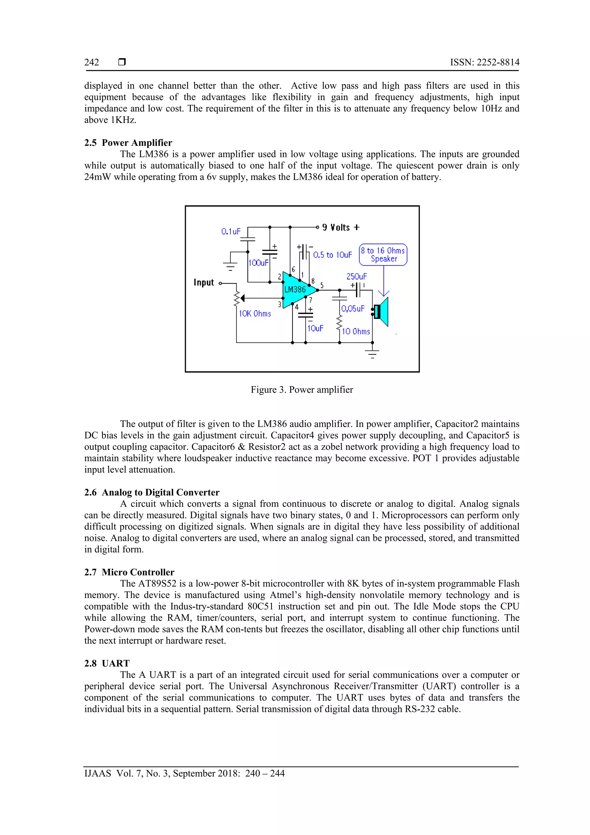
Preamplifier is used to amplify low level electrical signals for further processing. Filters allows
selection of suitable frequencies, so that particular heart sound frequencies can be reproduced. ADC converts](https://image.slidesharecdn.com/06-201022222535/75/Design-of-an-IOT-based-Online-Monitoring-Digital-Stethoscope-1-2048.jpg)

![ ISSN: 2252-8814
IJAAS Vol. 7, No. 3, September 2018: 240 – 244
244
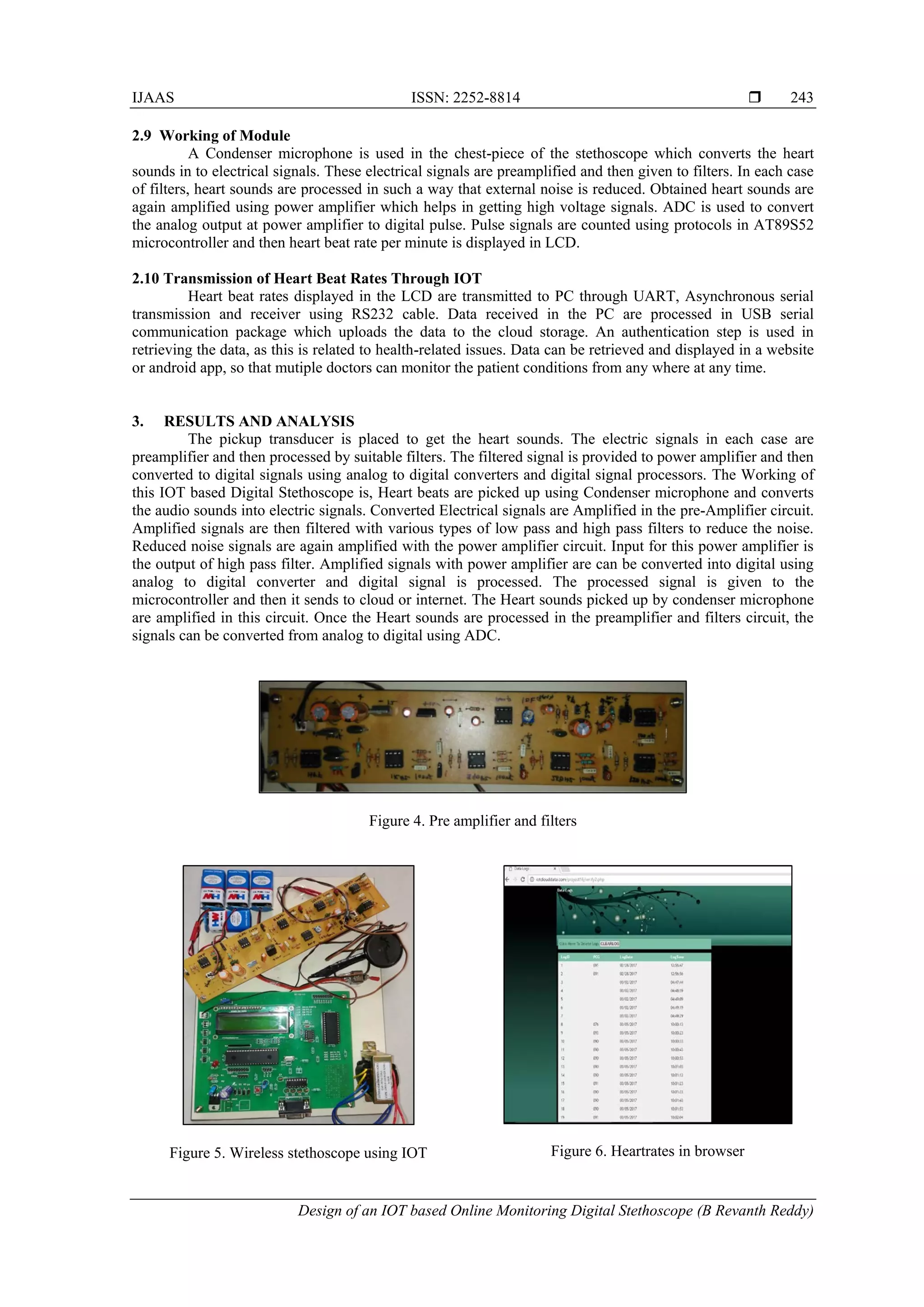
The pre amplifier, active filters and power amplifiers. The pickup transducer is placed to get the
heart sounds. The electric signals in each case are preamplifier and then processed by suitable filters.
Implemented wireless stethoscope using FM transmitter can be modified by converting analog to digital
signals using ADC and then can be sent to cloud using IOT techniques. Heartbeats counted by micro
controller is displayed in the LCD as well as in a site using IOT..
5. CONCLUSION
A Digital Stethoscope has been implemented and signals can be transmitted through IOT. Heart
beats are picked up using Condenser microphone and converts the audio sounds into electric signals.
Converted Electrical signals are Amplified in the pre-Amplifier circuit. Amplified signals are then filtered
with various types of low pass and high pass filters to reduce the noise. Reduced noise signals are again
amplified with the power amplifier circuit. Input for this power amplifier is the output of high pass filter.
Amplified signals with power amplifier are can be converted into digital using analog to digital converter and
digital signal is processed. The processed signal is given to the microcontroller and then it sends to cloud or
internet.
REFERENCES
[1] Habin Wang, Jian Chen, Choi Samjin, “Heart Sound Measurement and Analysis System with Digital
Stethoscope”, International Conference on Biomedical Engineering and Informatics, 2009.
[2] Yang Tang, Guitao Cao, Hao Li, “The design of electronic heart sound stethoscope based on Bluetooth”
4th International Conference On Bioinformatics and Biomedical Engineering (ICBBE), 2010.
[3] Ashish Harsola, Sushil Thale, M.S. Panse, “Digital Stethoscope for Heart Sounds”, International
Conference and workshop on Emerging Trends in Technology (ICWET), 2011.
[4] R. P. Singh, S.D. Sapre, “Communication Systems Analog & Digital” Second edition, Tata
McGrow–HillPublication.
[5] “Sound sending over internet” by david middlecamp published in adafruit, music, particle.
[6] ESP8266 Wi-Fi + Arduino upload to xively and Thingspeak byjanisalnis in Internet of Things.
[7] Wikipedia, https://en.wikipedia.org/wiki/Stethoscope](https://image.slidesharecdn.com/06-201022222535/75/Design-of-an-IOT-based-Online-Monitoring-Digital-Stethoscope-5-2048.jpg)