SlideShare a Scribd company logo
Visit the SIMULIA Resource Center for more customer examples.


     Design of Different Types of Corrugated Board
         Packages Using Finite Element Tools

               M. A. Jiménez-Caballero, I. Conde, B. García, E. Liarte
                                Instituto Tecnológico de Aragón
                         C/ María de Luna 7-8, 50007 Zaragoza. SPAIN
                                           www.ita.es
                        Email of corresponding author: majimenez@ita.es

Abstract: From a structural point of view, corrugated board would fit on the category of
sandwich structures, which in sectors as aeronautics or construction are today commonly
analysed using simulation tools that are based on the Finite Element Method. However, in spite
of similarities to applications in other materials, FEM simulation of corrugated board is a high
challenging modelling task due not only to the need of addressing properly the complex
mechanical modelling of paper itself, but also because of phenomena that are directly related to
the corrugated structure, as the relationships between local and global instability failure modes.
The present paper, through a set of application examples, shows how different Abaqus modelling
capabilities (SC8R elements, composite sections, connector elements, …) can be applied for
solving the different difficulties that arise when modelling corrugated board. The integration of
these capabilities has led to the development of virtual prototypes for the two most common
corrugated board packages: B1 boxes and agricultural trays. From the experience in these box
types, and taking advantage from the inherent modelling simplicity of the composite layered
models together to the flexibility offered by the available modelling techniques in Abaqus, these
virtual prototypes have been extended as a design tool for very different types of corrugated board
packages.
Keywords: Corrugated Board, Packaging, Box Compression,


1. Introduction

FE-based simulation has been increasingly used in the last decades as the main structural analysis
tool in many different industrial sectors and, in combination with other numerical techniques and
tools as CFD, has been also the main basis for the more recent concept of “virtual prototypes”
replacing manufacturing and testing of physical components. Starting in the past from civil
engineering, aeronautics and automotive industry, present applications of finite element simulation
extend to any industry sector as electronics, medical equipment, packaging, and more specifically
corrugated board packaging. In general terms, compression strength can be considered as the
most important requirement of a package, or at least the one that is common to all package types,
as during transport and storage, any box has to support without damage the weight of the rest of
the supported boxes; thus, initially, corrugated board industry has considered FEM as a possible


2009 SIMULIA Customer Conference                                                                1


             Visit the SIMULIA Resource Center for more customer examples.
tool for replacing the traditional application of semi-empirical expressions (Mc Kee et al. 1963)
looking for both, improved accuracy in the prediction of box compression strength using
numerical simulation of the package (Gilchrist et al. 1999, Rahman 1997, Urbanik et al. 2003,
Biancolini et al. 2003), and extending the analysis to package types as different as possible.
The introduction process of FE in corrugated board industry has been slower than in other sectors,
probably because of the very complex mechanical behaviour of both, paper itself and corrugated
board, leading to models that require very specific material models or advanced FE techniques.
However, and in spite of the slow start-up, applications of FEM to corrugated board industry are
rapidly growing, somehow taking advantage of previous developments in advanced modelling of
composites and composite sandwich structures, with relevant similarities to corrugated board. The
present paper summarises the general aspects of the simulation methodology that the authors are
applying for the structural analysis and design of corrugated board packages. The objective of the
paper is to provide a general description of the practical capabilities of the developed simulation
methodology, showing how Abaqus can be applied in the development process of corrugated
board packages, but without entering into detailed descriptions of a given finite element model or
simulation, nor presenting geometry and paper composition details of analysed packages.

2. GENERAL METHODOLOGY FOR FINITE ELEMENT SIMULATION
   OF CORRUGATED BOARD

2.1      Modelling the mechanical behaviour of paper

Resulting from the manufacturing process, paper is an orthotropic material with very different
mechanical properties in each of the three principal material orientation directions (Baum et al.
1981): through thickness direction (ZD), in-plane direction parallel to rolling during processing,
referred as machine direction (MD), and the in-plane direction normal to MD, referred as cross
direction (CD). Apart from orthotropy, paper behaviour exhibits two additional characteristics
that prevent from application of simple materials models: a) highly non linear behaviour, b) large
differences between tensile and compressive responses in any of both, MD and CD. Figure 1
shows the characteristic shape of the stress-strain curves in MD and CD.
                                        stress

                                                             Tensile curve in MD


                                                           Tensile curve in CD


                     Compressive curve in CD                            strain
                          Compressive
                          curve in MD


    Figure 1. Characteristic stress-strain curves of paper in machine direction (MD)
                                and cross direction (CD).

2                                                             2009 SIMULIA Customer Conference
Of course, paper behaviour exhibits additional characteristics that increase additionally the level of
complexity of modelling, as exhibiting significant creep, humidity dependence of mechanical
properties, higroexpansion, … In any case, it is important to remark that orthotropy, non-linearity
and differences tension-compression play all an important role even in the simple case of BCT
testing of a package under controlled room conditions, and because of this, mechanical modelling
of paper, even for the simpler loading cases always rely on the availability of a user developed
material model implementing as many as possible from the three referred characteristics plus
specific features for handling other property dependences if required by specific application (Xia
et al. 2002, Isaksson et al. 2004, Mäkela et al. 2003, Alfthan et al. 2005). In the examples that are
next presented, an in-plane orthotropic damage model with different treatment of tension and
compression and including definition of final paper failure according to the Tsai-Wu criterion
(Tryding, 1994) has been applied for modelling the static response of paper in the short-term using
shell elements; the model has been implement through UMAT and VUMAT user subroutines,
only shell element versions, in Abaqus/Standard and Abaqus/Explicit, while the required
transverse shear stiffness values for the shells are calculated using the out-of-plane shear elastic
moduli from the constituent papers. The model has been validated at paper level through
validation from ECT (edge crush test) and FCT (flat crust test) experimental results (Jiménez et al.
2003, Bielsa et al. 2006).
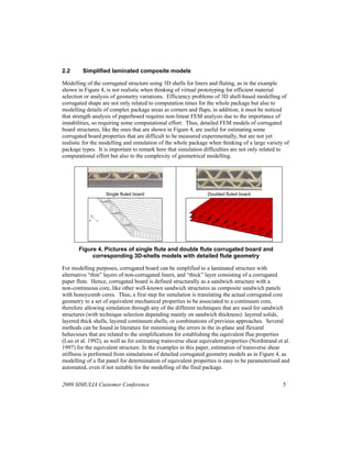
Figure 2 summarises as example the validation of the paper material model by simulating in
Abaqus/Explicit a FCT test of a single flute board by means of a single wave model in which
symmetry boundary conditions are applied in all the edges given the large dimensions of the FCT
sample (100 mm x 25 mm) when compared to the single wave. Results show how three
experimental load peaks can be identified along the test with deviations around to 10%. As
already expected when designing these validation tests, the differences in displacement prediction
are higher because of different reasons, including among these the simplifications in the modelling
of the adhesive and of the out-of-plane behaviour of the paper
                                                             1600
           Symmetry conditions for modelling a
           100mmx25mm FCT sample
                                                             1400
C3D8R elements for                                                        FCT test
adhesive                                                                  Simulation result
                                                             1200                                                  Total failure
                                                                                                                   extension
                                                             1000
                                                  Load (N)


                                                             800
                                                                                             Failure progression
                                                             600
                                                                        Failure initiation
                                                                        at creases
                                                             400

                                                             200


  C3D8R elements        S4R elements for liners               0
  for adhesive                                                      0   0,5              1             1,5              2          2,5
                        and fluting
                                                                                    Displacement (mm)


Figure 2. Comparison of simulation and experimental results for FCT simulation of
                           single flute paperboard.


2009 SIMULIA Customer Conference                                                                                                   3
As it will be presented in forthcoming parts of the paper, carrying trays for agricultural products
present, in addition to BCT qualification, another key requirement in terms of the so called
“bottom sag” under sustained load or creep. This requirement is established in terms of
displacement instead of strength, as the limit structural condition is determined by the possibility
of the bottom of a given try touching and damaging the fruits or vegetables that are packaged in
the box underneath. In order to cover creep, the material model of paper has been modified for
considering viscoelastic strains under sustained loads. The selected model is based on Coffin
equation for paper creep (Coffin, 2005) that considers potential and logarithmic behaviour (see
equation 1) and fulfils the needed conditions leading to the possibility of creating master curves
for paper through a logarithmic time shift in stress values (Brezinski, 1956). Coffin equation for
the creep modulus, J, is shown in Equation 1.

                 J
                        (t ) 1
                        0 E
                                                 
                              1  A 1  e at  B ln bt  1
                                              
                                                                                 
                                                                                                                1
The first term represents primary creep, which is considered a delayed response where A is the
inverse of elastic modulus of the delayed response, a is a time scale factor and  is the exponent of
the potential behaviour observed for short times. The second term represents secondary creep and
is based on Brezinski´s observation that long term creep is a lineal function of logarithm of time. B
is a creep flow parameter and b is a time scale factor. Figure 3 shows results from simulation of
patch tests with a single shell for tensile creep at different percentage of tensile failure stress,
together to results of the experimental creep tests that were used for determining the parameters of
the corresponding creep equation; results correspond to a recycled paper to be used as linerboard.
                                 2.50E-10


                                 2.00E-10
                      J (1/Pa)


                                 1.50E-10


                                 1.00E-10                                       — 10%
                                                                                — 20%
                                                                                — 40%
                                 5.00E-11
                                                                                — Simulation

                                 0.00E+00
                                            0    50000   100000 150000 200000 250000 300000 350000
                                                                  Tiem po (s)


    Figure 3. Results of creep characterisation of a sample paper and validation of
                user creep model for paper through tensile patch test

The modelling methodology that is proposed by the authors for BCT simulations and analysis of
box bottom sag (including creep) is based on Abaqus/Standard simulations, mainly because of
higher computational efficiency for most of the analysed cases. In any case, during the initial
stages of the methodology development, Abaqus/Explicit was also used from to time to time for
very specific simulations, as an easier way to extend analysis beyond specific instabilities as those
in the FCT example that has been previously presented (Figure 2).

4                                                                                 2009 SIMULIA Customer Conference
2.2      Simplified laminated composite models

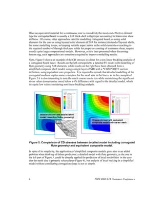
Modelling of the corrugated structure using 3D shells for liners and fluting, as in the example
shown in Figure 4, is not realistic when thinking of virtual prototyping for efficient material
selection or analysis of geometry variations. Efficiency problems of 3D shell-based modelling of
corrugated shape are not only related to computation times for the whole package but also to
modelling details of complex package areas as corners and flaps; in addition, it must be noticed
that strength analysis of paperboard requires non-linear FEM analysis due to the importance of
instabilities, so requiring some computational effort. Thus, detailed FEM models of corrugated
board structures, like the ones that are shown in Figure 4, are useful for estimating some
corrugated board properties that are difficult to be measured experimentally, but are not yet
realistic for the modelling and simulation of the whole package when thinking of a large variety of
package types. It is important to remark here that simulation difficulties are not only related to
computational effort but also to the complexity of geometrical modelling.


                        Single fluted board                      Doubled fluted board


                2

            3       1


       Figure 4. Pictures of single flute and double flute corrugated board and
            corresponding 3D-shells models with detailed flute geometry

For modelling purposes, corrugated board can be simplified to a laminated structure with
alternative “thin” layers of non-corrugated liners, and “thick” layer consisting of a corrugated
paper flute. Hence, corrugated board is defined structurally as a sandwich structure with a
non-continuous core, like other well-known sandwich structures as composite sandwich panels
with honeycomb cores. Thus, a first step for simulation is translating the actual corrugated core
geometry to a set of equivalent mechanical properties to be associated to a continuum core,
therefore allowing simulation through any of the different techniques that are used for sandwich
structures (with technique selection depending mainly on sandwich thickness): layered solids,
layered thick shells, layered continuum shells, or combinations of previous approaches. Several
methods can be found in literature for minimising the errors in the in-plane and flexural
behaviours that are related to the simplifications for establishing the equivalent flue properties
(Luo et al. 1992), as well as for estimating transverse shear equivalent properties (Nordstrand et al.
1997) for the equivalent structure. In the examples in this paper, estimation of transverse shear
stiffness is performed from simulations of detailed corrugated geometry models as in Figure 4, as
modelling of a flat panel for determination of equivalent properties is easy to be parameterised and
automated, even if not suitable for the modelling of the final package.

2009 SIMULIA Customer Conference                                                                  5
Once an equivalent material for a continuous core is considered, the most cost-effective element
type for corrugated board is usually a S4R thick-shell with proper accounting for transverse shear
stiffness. Of course, other approaches exist for modelling corrugated board, as using solid
elements for the core or using layered solid elements (C38R for instance) instead of layered shells,
but some modelling issues, as keeping suitable aspect ratios in the solid elements or reaching to
the required number of through thickness solids for proper accounting of transverse shear, require
usually quite large computational models. However, as it is later presented when discussing
bottom sag, such approaches are sometimes required to improve modelling results.
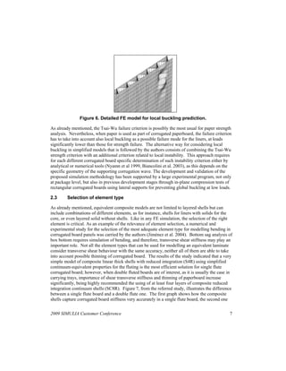
Next, Figure 5 shows an example of the CD stresses in a liner for a non-linear buckling analysis of
a corrugated board panel. Results on the left correspond to a detailed FE model with modelling of
flute geometry using S4R elements, while results on the right have been obtained from a
simplified composite shell model, using a single layer of S4R with a *COMPOSITE section
definition, using equivalent core properties. It is required to remark that detailed modelling of the
corrugated medium implies some restriction for the mesh size in the liners, so in the example of
Figure 5 it is also interesting to note the much coarser mesh size while maintaining the significant
stress values (compressive ones) below a 6% difference with regard to the detailed model, which
is a quite low value considering non-linear buckling analysis.


Figure 5. Comparison of CD stresses between detailed model including corrugated
                flute geometry and equivalent composite model.

In spite of its simplicity, the application of simplified composite models gives rise to an added
problem when thinking of failure prediction: a detailed model with flute geometry, as the one in
the left part of Figure 5, could be directly applied for prediction of local instabilities in the case
that the mesh size is properly selected (see Figure 6), but analysis of local bucking in a simplified
model without considering corrugation shape is not so simple.


6                                                               2009 SIMULIA Customer Conference
Figure 6. Detailed FE model for local buckling prediction.

As already mentioned, the Tsai-Wu failure criterion is possibly the most usual for paper strength
analysis. Nevertheless, when paper is used as part of corrugated paperboard, the failure criterion
has to take into account also local buckling as a possible failure mode for the liners, at loads
significantly lower than those for strength failure. The alternative way for considering local
buckling in simplified models that is followed by the authors consists of combining the Tsai-Wu
strength criterion with an additional criterion related to local instability. This approach requires
for each different corrugated board specific determination of such instability criterion either by
analytical or numerical tools (Nyamn et al 1999, Biancolini et al. 2003), as this depends on the
specific geometry of the supporting corrugation wave. The development and validation of the
proposed simulation methodology has been supported by a large experimental program, not only
at package level, but also in previous development stages through in-plane compression tests of
rectangular corrugated boards using lateral supports for preventing global buckling at low loads.

2.3      Selection of element type

As already mentioned, equivalent composite models are not limited to layered shells but can
include combinations of different elements, as for instance, shells for liners with solids for the
core, or even layered solid without shells. Like in any FE simulation, the selection of the right
element is critical. As an example of the relevance of element selection, a numerical and
experimental study for the selection of the most adequate element type for modelling bending in
corrugated board panels was carried by the authors (Jiménez et al. 2004). Bottom sag analysis of
box bottom requires simulation of bending, and therefore, transverse shear stiffness may play an
important role. Not all the element types that can be used for modelling an equivalent laminate
consider transverse shear behaviour with the same accuracy, neither all of them are able to take
into account possible thinning of corrugated board. The results of the study indicated that a very
simple model of composite linear thick shells with reduced integration (S4R) using simplified
continuum-equivalent properties for the fluting is the most efficient solution for single flute
corrugated board; however, when double fluted boards are of interest, as it is usually the case in
carrying trays, importance of shear transverse stiffness and thinning of paperboard increase
significantly, being highly recommended the using of at least four layers of composite reduced
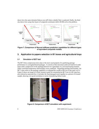
integration continuum shells (SC8R). Figure 7, from the referred study, illustrates the difference
between a single flute board and a double flute one. The first graph shows how the composite
shells capture corrugated board stiffness very accurately in a single flute board, the second one


2009 SIMULIA Customer Conference                                                                   7
shows how the same elements behaves too stiff when a double flute is analysed, finally, the third
one shows how using four layers of composite continuum shells (SC8R) solves the problem.


Figure 7. Comparison of flexural stiffness prediction capabilities for different types
                        of equivalent composite models.


3. Application to papers selection in B1 boxes and agricultural trays

3.1      Simulation of BCT test

The BCT (box compression test) value is the most usual property for qualifying package
performance in corrugated board packages. It consists of the maximum achieved load level under
quasi-static compression of the package between two rigid plates in a universal testing machine
under controlled temperature and humidity room conditions. Regarding package functionality, the
BCT value refers to the package capability to withstand the weight of the rest of the stack over it.
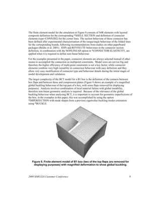
Figure 8 shows an image of a finite element model for simulating the BCT test of a B1-type box,
also referred as american box; it includes the final damaged areas together to a picture of a tested
sample, showing very good correlation in terms of predicting failure mode.


               Figure 8. Comparison of BCT simulation with experiment.

8                                                             2009 SIMULIA Customer Conference
The finite element model for the simulation in Figure 8 consists of S4R elements with layered
composite definition for the corresponding *SHELL SECTION and definition of connector
elements (type=CONN3D2) for the corner lines. The section behaviour of these connector has
been defined after experimental characterisation of the torque/angle behaviour of the folded lines
for the corresponding boards, following recommendations from studies on other paperboard
packages (Beldie et al. 2001). JOIN and REVOLUTE behaviours in the connector section
definition, in combination with the NONLINEAR option in *CONNECTOR ELASTICITY, are
applied when it is required to define non-linear behaviour.
For the examples presented in the paper, connector elements are always selected instead of other
means to accomplish the connection as multipoint constraints. Model sizes are not too big and
therefore the higher efficiency of multi-point constraints is not a key factor, while connector
elements combine very high versatility in connection behaviour with easy definition and they
allow very easy modification of connector type and behaviour details during the initial stages of
model development and validation.
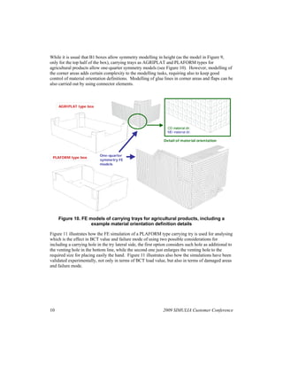
The larger complexity of the BCT model for a B1 box is the definition of the contacts between
box flaps and between these and compression plates (Figure 9 shows an example of a magnified
global buckling behaviour of the top part of a box, with some flaps removed for displaying
purposes). Analysis involves combination of local material failure with global instability,
therefore non-linear geometric analysis is required. Because of the relevance of the global
buckling behaviour when analysing BCT, it is important to account for geometric imperfections of
the box; in the examples in this paper, this was accomplished by using the option
*IMPERFECTION with mode shapes from a previous eigenvalue buckling modes estimation
using *BUCKLE.


   Figure 9. Finite element model of B1 box (two of the top flaps are removed for
    displaying purposes) with magnified deformation to show global buckling.


2009 SIMULIA Customer Conference                                                                9
While it is usual that B1 boxes allow symmetry modelling in height (as the model in Figure 9,
only for the top half of the box), carrying trays as AGRIPLAT and PLAFORM types for
agricultural products allow one-quarter symmetry models (see Figure 10). However, modelling of
the corner areas adds certain complexity to the modelling tasks, requiring also to keep good
control of material orientation definitions. Modelling of glue lines in corner areas and flaps can be
also carried out by using connector elements.


     AGRIPLAT type box


                                                                   CD material dir.
                                                                   MD material dir.

                                                                Detail of material orientation


                            One-quarter
 PLAFORM type box
                            symmetry FE
                            models


     Figure 10. FE models of carrying trays for agricultural products, including a
                    example material orientation definition details

Figure 11 illustrates how the FE simulation of a PLAFORM type carrying try is used for analysing
which is the effect in BCT value and failure mode of using two possible considerations for
including a carrying hole in the try lateral side, the first option considers such hole as additional to
the venting hole in the bottom line, while the second one just enlarges the venting hole to the
required size for placing easily the hand. Figure 11 illustrates also how the simulations have been
validated experimentally, not only in terms of BCT load value, but also in terms of damaged areas
and failure mode.


10                                                              2009 SIMULIA Customer Conference
Double hole: venting and carrying   Single larger hole with double function


  Figure 11. Validation of prediction of global failure areas in PLAFORM type box
              with different geometry for venting and carrying holes

Simulations following the proposed methodology present an error with regard to experimental
BCT values that is usually below 10% in terms of maximum load, which can be considered a very
low error if the complexity of material behaviour and failure mode (combining local buckling and
strength failure) is put together to other simulation details as torque-angle behavior of folded lines,
definition of glue lines, or non-linear analysis involving global buckling. Validation of all model
details for different packages has required a large experimental effort with monitoring of many
different variables during the test, as out-of-plane displacement of package faces or application of
high speed cameras for identifying onset of local buckling. Figure 12 shows an example of the
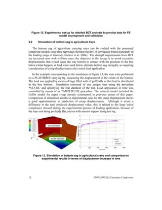
experimental set-up during the initial testing program for model development of agricultural trays.


                                                           BCT plate


                                                           LVDTs

                                                           Acquisition system
                                                           for LVDTs
                                                           Acquisition system
                                                           for LVDTs


                                                           Data cable from
                                                           universal test rig


      Computer   Lighting    Camera


2009 SIMULIA Customer Conference                                                                    11
Figure 12. Experimental set-up for detailed BCT analysis to provide data for FE
                          model development and validation

3.2                Simulation of bottom sag in agricultural trays

   The bottom sag of agriculture carrying trays can be studied with the presented
composite models since they reproduce flexural rigidity of corrugated board accurately in
the loading range of interest (Jiménez et al. 2004). The strength requirements from BCT
are increased now with stiffness ones; the objective in the design is to avoid excessive
displacements that would cause the tray bottom to contact with the products in the box
below (what happens at load levels well below ultimate bottom sag strength), so requiring
consideration of creep displacements after initial load application.
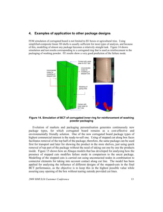
    In the example corresponding to the simulation in Figure 13, the tests were performed
on a PLAFORM carrying try, measuring the displacement in the centre of the bottom.
The load was applied by means of bags filled with of golf balls so that load is distributed
in the box bottom. Simulation consisted of one unique step using the procedure
*STATIC and specifying the real duration of the test. Load application in time was
controlled by means of an *AMPLITUDE procedure. The material model included the
Coffin model for paper creep already commented in previous points of this paper.
Comparison of simulation results to experimental ones for the creep displacement shows
a good approximation to prediction of creep displacements. Although it exists a
difference in the total predicted displacement value, this is related to the large initial
compliance showed during the experimental process of loading application, because of
the trays not being perfectly flat, and so with uneven support along test rig.
                                                                       8

         (m)                                                           7


                                                                       6
                                                  Displacement (mm)
                                                  Desplazamiento(mm)


                          S4R elements
                                                                       5


                                                                       4


                                                                       3
          3
     2
               1             SC8R elements                             2
                                                                                                              Test 1 1
                                                                                                              Ensayo

                                                                       1                                      Test 2 2
                                                                                                              Ensayo
                                                                                                              Simulation
                                                                                                              Simulacion
                                                                       0
                                                                           0   2000     4000          6000   8000          10000
                                                                                            Time (min)
                                                                                           Tiempo (min)


         Figure 13. Simulation of bottom sag in agricultural creep and comparison to
                experimental results in terms of displacement increase in time


12                                                                                    2009 SIMULIA Customer Conference
4. Examples of application to other package designs

FEM simulation of corrugated board is not limited to B1 boxes or agricultural tries. Using
simplified-composite linear 3D shells is usually sufficient for most types of analysis, and because
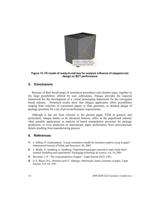
of this, modelling of almost any package becomes a relatively straight task. Figure 14 shows
simulation and test results corresponding to a corrugated ring that is used as reinforcement in the
packaging of washing powder. FE results show a very good prediction of the failure mode.

                                               Contact with upper
                                               plate for BCT test

                                                   Unconnected
                 Unconnected                       nodes for
                 nodes for                         modelling of
                 modelling of                      stepped cuts
                 stepped cuts


                                                Modeling of
                                                gluing lines with
                                                MPCs


                                              Contact with
                                              lower plate for
                                              BCT test


Figure 14. Simulation of BCT of corrugated inner ring for reinforcement of washing
                                powder packaging

    Evolution of markets and packaging personalisation generates continuously new
package types, for which corrugated board remains as a cost-effective and
environmentally friendly solution. One of the new corrugated board package types of
highest commercial interest is the ready-to-sell one. Using of stepped cut along box faces
facilitates removal of the top half of the package; therefore, the same package can be used
first for transport and later for showing the product in the store shelves, just using quick
removal of top part of the package without the need of taking out one by one the products
inside. Figure 15 shows how an Abaqus models that has developed for analysing how the
presence of stepped cuts modifies failure mode in comparison to the uncut package.
Modelling of the stepped cuts is carried out using unconnected nodes in combination to
connector elements for taking into account contact along cut line. The model has been
applied for analysing the influence of different designs of the stepped-cuts in the final
BCT performance, as the objective is to keep this in the highest possible value while
assuring easy opening of the box without tearing outside provided cut lines.

2009 SIMULIA Customer Conference                                                                 13
  
                                                                            
                                                                                
                                                                                                        
                                                                                                    
                                                                                                
                                                                                            
                                                                                        
                                                                                    
                                                                                
                                                                            
                                                                        
                                                                    
                                                                
                                     
                                                          
                                                      
                                                    

                                               Simulation of stepped die-cuts
                                                                           Conecto
                                                                           rigidez
                                               by means of connector elements
                                               along unconnected node lines


     Figure 15. FE model of ready-to-sell box for analysis influence of stepped-cuts
                              design on BCT performance


5. Conclusions

   Because of their broad range of simulation procedures and element types, together to
the large possibilities offered by user subroutines, Abaqus provides the required
framework for the development of a virtual prototyping framework for the corrugated
board industry. Presented results show that Abaqus application offers possibilities
ranging from selection of constituent papers or flute geometry, to detailed design of
package geometry for a set of given performance requirements.
   Although it has not been referred in the present paper, FEM in general, and
particularly Abaqus thanks to its advanced features, offers to the paperboard industry
other possible applications as analysis of board manipulation processes for package
production, or even prediction of macroscopic paper performance from microstructure
details resulting from manufacturing process.

6. References

1. J. Alfthan, P. Gudmundson. “Linear constitutive model for mechano-sorptive creep in paper”.
   International Journal of Solids and Structures, 42, 2005.
2. L. Beldie; G. Sandberg; L. Sandberg, “Paperboard packages exposed to static loads-finite
   element modelling and experiments“ Packaging technology & science, vol. 14, 2001.
3. Brezinski, J. P. “The creep properties of paper”. Tappi Journal 39(2), 1956.
4. G.A. Baum, D.C., Brennan and CC .Habeger, Orthotropic elastic constants of paper, Tappi
   Journal, Vol. 64, 1981.


14                                                                                              2009 SIMULIA Customer Conference
5. M. E. Biancolini and C. Brutti, “Numerical and experimental investigation of the strength of
   corrugated board packages”, Packaging Technology and Science, Vol. 16(2), March 2003.
6. J.M. Bielsa, R. Rodriguez, L. Vila, M. A. Jiménez, “Parametrized finite element analysis of
   tribological instabilities on polymer-metal sliding contacts”, III ECCM, Lisbon 2006.
7. Coffin, D. W., “The creep response of paper”, 13th Fundamental Research Symposium,
   Cambridge, 2005
8. A.C. Gilchrist, J.C. Suhling, T.J. Urbanik. “Nonlinear finite element modeling of corrugated
   board”. Mechanics of Cellulosic Materials, 1999, AMD-Vol. 231/MD-Vol. 85, 1999.
9. P. Isaksson, R. Hägglundb,P. Gradina. “Continuum damage mechanics applied to paper”.
   International Journal of Solids and Structures, 41, 2004.
10. M.A. Jiménez, I. Conde, E. Liarte, E. Mozas. “Modelling of bending in a corrugated board”,
    International Paper Physics Seminar, Trondheim 2004
11. M.A. Jiménez, E. Liarte. “Simulation of the Edge Crush Test of corrugated paperboard using
    Abaqus”, Abaqus World Users Conference 2003, Munich.
12. P. Mäkelä, S. Östlund. “Orthotropic elastic–plastic material model for paper materials”.
    International Journal of Solids and Structures, 40, 2003.
13. R.C. Mc Kee, J.W. Gander, J.R. Wachuta. “Compression Strength Formula for Corrugated
    Board”. Paperboard Packaging, Aug 1963
14. T. Nordstrand, L.A. Carlsson, Evaluation of Transverse Shear Stiffness of Structural Core
    Sandwich Plates, Composite Structures, Vol. 37, 1997.
15. U. Nyman, P.J. Gustafsson, “Local buckling of corrugated board facings, Proceedings of the
    European Conference on Computational Mechanics”, Munich 1999.
16. S. Luo, J. C. Suhling, The bending stiffness of corrugated board, Mechanics of Cellulosic
    Materials AMD-Vol. 145/MD-Vol. 36, 1992.
17. A.A. Rahman. “Finite Element Buckling Analysis of Corrugated Fiberboard Panels”. ASME
    Symposium on Cellulosic Materials, AMD-Vol.221, 1997, Evanston.
18. J. Tryding, A modification of the Tsai-Wu failure criterion for the biaxial strength of paper,
    Tappi Journal, Vol. 77, 1994
19. T.J. Urbanik, E.P. Saliklis. “Finite element corroboration of buckling phenomena observed in
    corrugated boxes”. Wood and Fiber Science, 35(3), 2003.
20. Q.S. Xia, M.C. Boyce, D.M. Parks. “A Constitutive Model for the Anisotropic Elastic-Plastic
    Deformation of Paper and Paperboard”. Int. Journal of Solids and Structures, 39, 2002.

7. Acknowledgments

This paper presents results from a research programme carried out with the support from SAICA.
The authors thank specially to the personnel of the Research and Development Laboratory of
SAICA for their invaluable contributions in the preparation and experimental characterisation of
paper, corrugated board and packages, as well as in all the practical aspects related to corrugated
board processing and package converting.

2009 SIMULIA Customer Conference                                                                 15


             Visit the SIMULIA Resource Center for more customer examples.

More Related Content

Similar to Design of Different Types of Corrugated Board Packages Using Finite Element Tools

METHOD FOR OPTIMIZATION OF COMPOSITE SANDWICH STRUCTURE USING ARTIFICIAL NEUR...
METHOD FOR OPTIMIZATION OF COMPOSITE SANDWICH STRUCTURE USING ARTIFICIAL NEUR...METHOD FOR OPTIMIZATION OF COMPOSITE SANDWICH STRUCTURE USING ARTIFICIAL NEUR...
METHOD FOR OPTIMIZATION OF COMPOSITE SANDWICH STRUCTURE USING ARTIFICIAL NEUR...
IRJET Journal
 
Static Structural, Fatigue and Buckling Analysis of Jet Pipe Liner by Inducin...
Static Structural, Fatigue and Buckling Analysis of Jet Pipe Liner by Inducin...Static Structural, Fatigue and Buckling Analysis of Jet Pipe Liner by Inducin...
Static Structural, Fatigue and Buckling Analysis of Jet Pipe Liner by Inducin...
IRJET Journal
 
Warpage simulation of manhole cover using auto cast x software
Warpage simulation of manhole cover using auto cast x softwareWarpage simulation of manhole cover using auto cast x software
Warpage simulation of manhole cover using auto cast x software
Laukik Raut
 
Effect of lamination angle on maximum deflection of simply supported composit...
Effect of lamination angle on maximum deflection of simply supported composit...Effect of lamination angle on maximum deflection of simply supported composit...
Effect of lamination angle on maximum deflection of simply supported composit...
RAVI KUMAR
 
H1075262
H1075262H1075262
H1075262
IJERD Editor
 
International Journal of Engineering Research and Development
International Journal of Engineering Research and DevelopmentInternational Journal of Engineering Research and Development
International Journal of Engineering Research and Development
IJERD Editor
 
IRJET- Vibro Acoustic Analysis of Laminated Composite Plate Roof of Car Body
IRJET- Vibro Acoustic Analysis of Laminated Composite Plate Roof of Car BodyIRJET- Vibro Acoustic Analysis of Laminated Composite Plate Roof of Car Body
IRJET- Vibro Acoustic Analysis of Laminated Composite Plate Roof of Car Body
IRJET Journal
 
Q24126128
Q24126128Q24126128
Q24126128
IJERA Editor
 
Lj3519471951
Lj3519471951Lj3519471951
Lj3519471951
IJERA Editor
 
Optimization of Multi Leaf Spring by using Design of Experiments & Simulated ...
Optimization of Multi Leaf Spring by using Design of Experiments & Simulated ...Optimization of Multi Leaf Spring by using Design of Experiments & Simulated ...
Optimization of Multi Leaf Spring by using Design of Experiments & Simulated ...
IJMER
 
IRJET - Experimental Investigation of Carbon Fiber Reinforcement T-Stiffe...
IRJET -  	  Experimental Investigation of Carbon Fiber Reinforcement T-Stiffe...IRJET -  	  Experimental Investigation of Carbon Fiber Reinforcement T-Stiffe...
IRJET - Experimental Investigation of Carbon Fiber Reinforcement T-Stiffe...
IRJET Journal
 
Warping and Residual Stress Analysis using the Abaqus Interface for Moldflow
Warping and Residual Stress Analysis using the Abaqus Interface for MoldflowWarping and Residual Stress Analysis using the Abaqus Interface for Moldflow
Warping and Residual Stress Analysis using the Abaqus Interface for Moldflow
SIMULIA
 
Karimanal chipstacking fea_draft_corrected
Karimanal chipstacking fea_draft_correctedKarimanal chipstacking fea_draft_corrected
Karimanal chipstacking fea_draft_corrected
Kamal Karimanal
 
IRJET- Design and Analysis of Composite Top Frame of Hydraulic Valve Test...
IRJET-  	  Design and Analysis of Composite Top Frame of Hydraulic Valve Test...IRJET-  	  Design and Analysis of Composite Top Frame of Hydraulic Valve Test...
IRJET- Design and Analysis of Composite Top Frame of Hydraulic Valve Test...
IRJET Journal
 
1445003126-Fatigue Analysis of a Welded Assembly.pdf
1445003126-Fatigue Analysis of a Welded Assembly.pdf1445003126-Fatigue Analysis of a Welded Assembly.pdf
1445003126-Fatigue Analysis of a Welded Assembly.pdf
ssusercf6d0e
 
IRJET-Cyclic Response of Perforated Beam in Steel Column Joints
IRJET-Cyclic Response of Perforated Beam in Steel Column JointsIRJET-Cyclic Response of Perforated Beam in Steel Column Joints
IRJET-Cyclic Response of Perforated Beam in Steel Column Joints
IRJET Journal
 
IRJET- Estimation of Stress Intensity Factor for the different Crack Mode...
IRJET-  	  Estimation of Stress Intensity Factor for the different Crack Mode...IRJET-  	  Estimation of Stress Intensity Factor for the different Crack Mode...
IRJET- Estimation of Stress Intensity Factor for the different Crack Mode...
IRJET Journal
 
Dx2645324539
Dx2645324539Dx2645324539
Dx2645324539IJMER
 
Paper - The use of FEM for composites
Paper - The use of FEM for compositesPaper - The use of FEM for composites
Paper - The use of FEM for compositesMichael Armbruster
 

Similar to Design of Different Types of Corrugated Board Packages Using Finite Element Tools (20)

METHOD FOR OPTIMIZATION OF COMPOSITE SANDWICH STRUCTURE USING ARTIFICIAL NEUR...
METHOD FOR OPTIMIZATION OF COMPOSITE SANDWICH STRUCTURE USING ARTIFICIAL NEUR...METHOD FOR OPTIMIZATION OF COMPOSITE SANDWICH STRUCTURE USING ARTIFICIAL NEUR...
METHOD FOR OPTIMIZATION OF COMPOSITE SANDWICH STRUCTURE USING ARTIFICIAL NEUR...
 
Static Structural, Fatigue and Buckling Analysis of Jet Pipe Liner by Inducin...
Static Structural, Fatigue and Buckling Analysis of Jet Pipe Liner by Inducin...Static Structural, Fatigue and Buckling Analysis of Jet Pipe Liner by Inducin...
Static Structural, Fatigue and Buckling Analysis of Jet Pipe Liner by Inducin...
 
Warpage simulation of manhole cover using auto cast x software
Warpage simulation of manhole cover using auto cast x softwareWarpage simulation of manhole cover using auto cast x software
Warpage simulation of manhole cover using auto cast x software
 
Effect of lamination angle on maximum deflection of simply supported composit...
Effect of lamination angle on maximum deflection of simply supported composit...Effect of lamination angle on maximum deflection of simply supported composit...
Effect of lamination angle on maximum deflection of simply supported composit...
 
H1075262
H1075262H1075262
H1075262
 
International Journal of Engineering Research and Development
International Journal of Engineering Research and DevelopmentInternational Journal of Engineering Research and Development
International Journal of Engineering Research and Development
 
IRJET- Vibro Acoustic Analysis of Laminated Composite Plate Roof of Car Body
IRJET- Vibro Acoustic Analysis of Laminated Composite Plate Roof of Car BodyIRJET- Vibro Acoustic Analysis of Laminated Composite Plate Roof of Car Body
IRJET- Vibro Acoustic Analysis of Laminated Composite Plate Roof of Car Body
 
Q24126128
Q24126128Q24126128
Q24126128
 
Lj3519471951
Lj3519471951Lj3519471951
Lj3519471951
 
Optimization of Multi Leaf Spring by using Design of Experiments & Simulated ...
Optimization of Multi Leaf Spring by using Design of Experiments & Simulated ...Optimization of Multi Leaf Spring by using Design of Experiments & Simulated ...
Optimization of Multi Leaf Spring by using Design of Experiments & Simulated ...
 
IRJET - Experimental Investigation of Carbon Fiber Reinforcement T-Stiffe...
IRJET -  	  Experimental Investigation of Carbon Fiber Reinforcement T-Stiffe...IRJET -  	  Experimental Investigation of Carbon Fiber Reinforcement T-Stiffe...
IRJET - Experimental Investigation of Carbon Fiber Reinforcement T-Stiffe...
 
Warping and Residual Stress Analysis using the Abaqus Interface for Moldflow
Warping and Residual Stress Analysis using the Abaqus Interface for MoldflowWarping and Residual Stress Analysis using the Abaqus Interface for Moldflow
Warping and Residual Stress Analysis using the Abaqus Interface for Moldflow
 
Ig2414511458
Ig2414511458Ig2414511458
Ig2414511458
 
Karimanal chipstacking fea_draft_corrected
Karimanal chipstacking fea_draft_correctedKarimanal chipstacking fea_draft_corrected
Karimanal chipstacking fea_draft_corrected
 
IRJET- Design and Analysis of Composite Top Frame of Hydraulic Valve Test...
IRJET-  	  Design and Analysis of Composite Top Frame of Hydraulic Valve Test...IRJET-  	  Design and Analysis of Composite Top Frame of Hydraulic Valve Test...
IRJET- Design and Analysis of Composite Top Frame of Hydraulic Valve Test...
 
1445003126-Fatigue Analysis of a Welded Assembly.pdf
1445003126-Fatigue Analysis of a Welded Assembly.pdf1445003126-Fatigue Analysis of a Welded Assembly.pdf
1445003126-Fatigue Analysis of a Welded Assembly.pdf
 
IRJET-Cyclic Response of Perforated Beam in Steel Column Joints
IRJET-Cyclic Response of Perforated Beam in Steel Column JointsIRJET-Cyclic Response of Perforated Beam in Steel Column Joints
IRJET-Cyclic Response of Perforated Beam in Steel Column Joints
 
IRJET- Estimation of Stress Intensity Factor for the different Crack Mode...
IRJET-  	  Estimation of Stress Intensity Factor for the different Crack Mode...IRJET-  	  Estimation of Stress Intensity Factor for the different Crack Mode...
IRJET- Estimation of Stress Intensity Factor for the different Crack Mode...
 
Dx2645324539
Dx2645324539Dx2645324539
Dx2645324539
 
Paper - The use of FEM for composites
Paper - The use of FEM for compositesPaper - The use of FEM for composites
Paper - The use of FEM for composites
 

More from SIMULIA

Multi-Physics Analysis of a Refractory Metal ACOperated High Temperature Heat...
Multi-Physics Analysis of a Refractory Metal ACOperated High Temperature Heat...Multi-Physics Analysis of a Refractory Metal ACOperated High Temperature Heat...
Multi-Physics Analysis of a Refractory Metal ACOperated High Temperature Heat...
SIMULIA
 
Welding Simulation with Abaqus
Welding Simulation with AbaqusWelding Simulation with Abaqus
Welding Simulation with Abaqus
SIMULIA
 
Determination of Critical Flaw Size in Gun Launched 40mm Grenade
Determination of Critical Flaw Size in Gun Launched 40mm GrenadeDetermination of Critical Flaw Size in Gun Launched 40mm Grenade
Determination of Critical Flaw Size in Gun Launched 40mm Grenade
SIMULIA
 
Earth Penetration Simulation using Coupled Eulerian-Lagrangian Analysis
Earth Penetration Simulation using Coupled Eulerian-Lagrangian AnalysisEarth Penetration Simulation using Coupled Eulerian-Lagrangian Analysis
Earth Penetration Simulation using Coupled Eulerian-Lagrangian Analysis
SIMULIA
 
Coupled Euler Lagrangian Approach Using Abaqus /Explicit in the Bird Strike A...
Coupled Euler Lagrangian Approach Using Abaqus /Explicit in the Bird Strike A...Coupled Euler Lagrangian Approach Using Abaqus /Explicit in the Bird Strike A...
Coupled Euler Lagrangian Approach Using Abaqus /Explicit in the Bird Strike A...
SIMULIA
 
Simulation of Airbag Deployment Using the Coupled Eulerian-Lagrangian Method ...
Simulation of Airbag Deployment Using the Coupled Eulerian-Lagrangian Method ...Simulation of Airbag Deployment Using the Coupled Eulerian-Lagrangian Method ...
Simulation of Airbag Deployment Using the Coupled Eulerian-Lagrangian Method ...
SIMULIA
 
Analysis of Casing Connections Subjected to Thermal Cycle Loading
Analysis of Casing Connections Subjected to Thermal Cycle LoadingAnalysis of Casing Connections Subjected to Thermal Cycle Loading
Analysis of Casing Connections Subjected to Thermal Cycle Loading
SIMULIA
 
Achieving a more Accurate Prediction of a Polymer Snap Deformation Pattern
Achieving a more Accurate Prediction of a Polymer Snap Deformation PatternAchieving a more Accurate Prediction of a Polymer Snap Deformation Pattern
Achieving a more Accurate Prediction of a Polymer Snap Deformation Pattern
SIMULIA
 

More from SIMULIA (8)

Multi-Physics Analysis of a Refractory Metal ACOperated High Temperature Heat...
Multi-Physics Analysis of a Refractory Metal ACOperated High Temperature Heat...Multi-Physics Analysis of a Refractory Metal ACOperated High Temperature Heat...
Multi-Physics Analysis of a Refractory Metal ACOperated High Temperature Heat...
 
Welding Simulation with Abaqus
Welding Simulation with AbaqusWelding Simulation with Abaqus
Welding Simulation with Abaqus
 
Determination of Critical Flaw Size in Gun Launched 40mm Grenade
Determination of Critical Flaw Size in Gun Launched 40mm GrenadeDetermination of Critical Flaw Size in Gun Launched 40mm Grenade
Determination of Critical Flaw Size in Gun Launched 40mm Grenade
 
Earth Penetration Simulation using Coupled Eulerian-Lagrangian Analysis
Earth Penetration Simulation using Coupled Eulerian-Lagrangian AnalysisEarth Penetration Simulation using Coupled Eulerian-Lagrangian Analysis
Earth Penetration Simulation using Coupled Eulerian-Lagrangian Analysis
 
Coupled Euler Lagrangian Approach Using Abaqus /Explicit in the Bird Strike A...
Coupled Euler Lagrangian Approach Using Abaqus /Explicit in the Bird Strike A...Coupled Euler Lagrangian Approach Using Abaqus /Explicit in the Bird Strike A...
Coupled Euler Lagrangian Approach Using Abaqus /Explicit in the Bird Strike A...
 
Simulation of Airbag Deployment Using the Coupled Eulerian-Lagrangian Method ...
Simulation of Airbag Deployment Using the Coupled Eulerian-Lagrangian Method ...Simulation of Airbag Deployment Using the Coupled Eulerian-Lagrangian Method ...
Simulation of Airbag Deployment Using the Coupled Eulerian-Lagrangian Method ...
 
Analysis of Casing Connections Subjected to Thermal Cycle Loading
Analysis of Casing Connections Subjected to Thermal Cycle LoadingAnalysis of Casing Connections Subjected to Thermal Cycle Loading
Analysis of Casing Connections Subjected to Thermal Cycle Loading
 
Achieving a more Accurate Prediction of a Polymer Snap Deformation Pattern
Achieving a more Accurate Prediction of a Polymer Snap Deformation PatternAchieving a more Accurate Prediction of a Polymer Snap Deformation Pattern
Achieving a more Accurate Prediction of a Polymer Snap Deformation Pattern
 

Recently uploaded

Alt. GDG Cloud Southlake #33: Boule & Rebala: Effective AppSec in SDLC using ...
Alt. GDG Cloud Southlake #33: Boule & Rebala: Effective AppSec in SDLC using ...Alt. GDG Cloud Southlake #33: Boule & Rebala: Effective AppSec in SDLC using ...
Alt. GDG Cloud Southlake #33: Boule & Rebala: Effective AppSec in SDLC using ...
James Anderson
 
SAP Sapphire 2024 - ASUG301 building better apps with SAP Fiori.pdf
SAP Sapphire 2024 - ASUG301 building better apps with SAP Fiori.pdfSAP Sapphire 2024 - ASUG301 building better apps with SAP Fiori.pdf
SAP Sapphire 2024 - ASUG301 building better apps with SAP Fiori.pdf
Peter Spielvogel
 
Accelerate your Kubernetes clusters with Varnish Caching
Accelerate your Kubernetes clusters with Varnish CachingAccelerate your Kubernetes clusters with Varnish Caching
Accelerate your Kubernetes clusters with Varnish Caching
Thijs Feryn
 
UiPath Test Automation using UiPath Test Suite series, part 4
UiPath Test Automation using UiPath Test Suite series, part 4UiPath Test Automation using UiPath Test Suite series, part 4
UiPath Test Automation using UiPath Test Suite series, part 4
DianaGray10
 
Enhancing Performance with Globus and the Science DMZ
Enhancing Performance with Globus and the Science DMZEnhancing Performance with Globus and the Science DMZ
Enhancing Performance with Globus and the Science DMZ
Globus
 
GDG Cloud Southlake #33: Boule & Rebala: Effective AppSec in SDLC using Deplo...
GDG Cloud Southlake #33: Boule & Rebala: Effective AppSec in SDLC using Deplo...GDG Cloud Southlake #33: Boule & Rebala: Effective AppSec in SDLC using Deplo...
GDG Cloud Southlake #33: Boule & Rebala: Effective AppSec in SDLC using Deplo...
James Anderson
 
Monitoring Java Application Security with JDK Tools and JFR Events
Monitoring Java Application Security with JDK Tools and JFR EventsMonitoring Java Application Security with JDK Tools and JFR Events
Monitoring Java Application Security with JDK Tools and JFR Events
Ana-Maria Mihalceanu
 
PCI PIN Basics Webinar from the Controlcase Team
PCI PIN Basics Webinar from the Controlcase TeamPCI PIN Basics Webinar from the Controlcase Team
PCI PIN Basics Webinar from the Controlcase Team
ControlCase
 
Video Streaming: Then, Now, and in the Future
Video Streaming: Then, Now, and in the FutureVideo Streaming: Then, Now, and in the Future
Video Streaming: Then, Now, and in the Future
Alpen-Adria-Universität
 
Removing Uninteresting Bytes in Software Fuzzing
Removing Uninteresting Bytes in Software FuzzingRemoving Uninteresting Bytes in Software Fuzzing
Removing Uninteresting Bytes in Software Fuzzing
Aftab Hussain
 
Smart TV Buyer Insights Survey 2024 by 91mobiles.pdf
Smart TV Buyer Insights Survey 2024 by 91mobiles.pdfSmart TV Buyer Insights Survey 2024 by 91mobiles.pdf
Smart TV Buyer Insights Survey 2024 by 91mobiles.pdf
91mobiles
 
By Design, not by Accident - Agile Venture Bolzano 2024
By Design, not by Accident - Agile Venture Bolzano 2024By Design, not by Accident - Agile Venture Bolzano 2024
By Design, not by Accident - Agile Venture Bolzano 2024
Pierluigi Pugliese
 
Climate Impact of Software Testing at Nordic Testing Days
Climate Impact of Software Testing at Nordic Testing DaysClimate Impact of Software Testing at Nordic Testing Days
Climate Impact of Software Testing at Nordic Testing Days
Kari Kakkonen
 
FIDO Alliance Osaka Seminar: The WebAuthn API and Discoverable Credentials.pdf
FIDO Alliance Osaka Seminar: The WebAuthn API and Discoverable Credentials.pdfFIDO Alliance Osaka Seminar: The WebAuthn API and Discoverable Credentials.pdf
FIDO Alliance Osaka Seminar: The WebAuthn API and Discoverable Credentials.pdf
FIDO Alliance
 
Securing your Kubernetes cluster_ a step-by-step guide to success !
Securing your Kubernetes cluster_ a step-by-step guide to success !Securing your Kubernetes cluster_ a step-by-step guide to success !
Securing your Kubernetes cluster_ a step-by-step guide to success !
KatiaHIMEUR1
 
Essentials of Automations: The Art of Triggers and Actions in FME
Essentials of Automations: The Art of Triggers and Actions in FMEEssentials of Automations: The Art of Triggers and Actions in FME
Essentials of Automations: The Art of Triggers and Actions in FME
Safe Software
 
Elizabeth Buie - Older adults: Are we really designing for our future selves?
Elizabeth Buie - Older adults: Are we really designing for our future selves?Elizabeth Buie - Older adults: Are we really designing for our future selves?
Elizabeth Buie - Older adults: Are we really designing for our future selves?
Nexer Digital
 
Le nuove frontiere dell'AI nell'RPA con UiPath Autopilot™
Le nuove frontiere dell'AI nell'RPA con UiPath Autopilot™Le nuove frontiere dell'AI nell'RPA con UiPath Autopilot™
Le nuove frontiere dell'AI nell'RPA con UiPath Autopilot™
UiPathCommunity
 
Secstrike : Reverse Engineering & Pwnable tools for CTF.pptx
Secstrike : Reverse Engineering & Pwnable tools for CTF.pptxSecstrike : Reverse Engineering & Pwnable tools for CTF.pptx
Secstrike : Reverse Engineering & Pwnable tools for CTF.pptx
nkrafacyberclub
 
Encryption in Microsoft 365 - ExpertsLive Netherlands 2024
Encryption in Microsoft 365 - ExpertsLive Netherlands 2024Encryption in Microsoft 365 - ExpertsLive Netherlands 2024
Encryption in Microsoft 365 - ExpertsLive Netherlands 2024
Albert Hoitingh
 

Recently uploaded (20)

Alt. GDG Cloud Southlake #33: Boule & Rebala: Effective AppSec in SDLC using ...
Alt. GDG Cloud Southlake #33: Boule & Rebala: Effective AppSec in SDLC using ...Alt. GDG Cloud Southlake #33: Boule & Rebala: Effective AppSec in SDLC using ...
Alt. GDG Cloud Southlake #33: Boule & Rebala: Effective AppSec in SDLC using ...
 
SAP Sapphire 2024 - ASUG301 building better apps with SAP Fiori.pdf
SAP Sapphire 2024 - ASUG301 building better apps with SAP Fiori.pdfSAP Sapphire 2024 - ASUG301 building better apps with SAP Fiori.pdf
SAP Sapphire 2024 - ASUG301 building better apps with SAP Fiori.pdf
 
Accelerate your Kubernetes clusters with Varnish Caching
Accelerate your Kubernetes clusters with Varnish CachingAccelerate your Kubernetes clusters with Varnish Caching
Accelerate your Kubernetes clusters with Varnish Caching
 
UiPath Test Automation using UiPath Test Suite series, part 4
UiPath Test Automation using UiPath Test Suite series, part 4UiPath Test Automation using UiPath Test Suite series, part 4
UiPath Test Automation using UiPath Test Suite series, part 4
 
Enhancing Performance with Globus and the Science DMZ
Enhancing Performance with Globus and the Science DMZEnhancing Performance with Globus and the Science DMZ
Enhancing Performance with Globus and the Science DMZ
 
GDG Cloud Southlake #33: Boule & Rebala: Effective AppSec in SDLC using Deplo...
GDG Cloud Southlake #33: Boule & Rebala: Effective AppSec in SDLC using Deplo...GDG Cloud Southlake #33: Boule & Rebala: Effective AppSec in SDLC using Deplo...
GDG Cloud Southlake #33: Boule & Rebala: Effective AppSec in SDLC using Deplo...
 
Monitoring Java Application Security with JDK Tools and JFR Events
Monitoring Java Application Security with JDK Tools and JFR EventsMonitoring Java Application Security with JDK Tools and JFR Events
Monitoring Java Application Security with JDK Tools and JFR Events
 
PCI PIN Basics Webinar from the Controlcase Team
PCI PIN Basics Webinar from the Controlcase TeamPCI PIN Basics Webinar from the Controlcase Team
PCI PIN Basics Webinar from the Controlcase Team
 
Video Streaming: Then, Now, and in the Future
Video Streaming: Then, Now, and in the FutureVideo Streaming: Then, Now, and in the Future
Video Streaming: Then, Now, and in the Future
 
Removing Uninteresting Bytes in Software Fuzzing
Removing Uninteresting Bytes in Software FuzzingRemoving Uninteresting Bytes in Software Fuzzing
Removing Uninteresting Bytes in Software Fuzzing
 
Smart TV Buyer Insights Survey 2024 by 91mobiles.pdf
Smart TV Buyer Insights Survey 2024 by 91mobiles.pdfSmart TV Buyer Insights Survey 2024 by 91mobiles.pdf
Smart TV Buyer Insights Survey 2024 by 91mobiles.pdf
 
By Design, not by Accident - Agile Venture Bolzano 2024
By Design, not by Accident - Agile Venture Bolzano 2024By Design, not by Accident - Agile Venture Bolzano 2024
By Design, not by Accident - Agile Venture Bolzano 2024
 
Climate Impact of Software Testing at Nordic Testing Days
Climate Impact of Software Testing at Nordic Testing DaysClimate Impact of Software Testing at Nordic Testing Days
Climate Impact of Software Testing at Nordic Testing Days
 
FIDO Alliance Osaka Seminar: The WebAuthn API and Discoverable Credentials.pdf
FIDO Alliance Osaka Seminar: The WebAuthn API and Discoverable Credentials.pdfFIDO Alliance Osaka Seminar: The WebAuthn API and Discoverable Credentials.pdf
FIDO Alliance Osaka Seminar: The WebAuthn API and Discoverable Credentials.pdf
 
Securing your Kubernetes cluster_ a step-by-step guide to success !
Securing your Kubernetes cluster_ a step-by-step guide to success !Securing your Kubernetes cluster_ a step-by-step guide to success !
Securing your Kubernetes cluster_ a step-by-step guide to success !
 
Essentials of Automations: The Art of Triggers and Actions in FME
Essentials of Automations: The Art of Triggers and Actions in FMEEssentials of Automations: The Art of Triggers and Actions in FME
Essentials of Automations: The Art of Triggers and Actions in FME
 
Elizabeth Buie - Older adults: Are we really designing for our future selves?
Elizabeth Buie - Older adults: Are we really designing for our future selves?Elizabeth Buie - Older adults: Are we really designing for our future selves?
Elizabeth Buie - Older adults: Are we really designing for our future selves?
 
Le nuove frontiere dell'AI nell'RPA con UiPath Autopilot™
Le nuove frontiere dell'AI nell'RPA con UiPath Autopilot™Le nuove frontiere dell'AI nell'RPA con UiPath Autopilot™
Le nuove frontiere dell'AI nell'RPA con UiPath Autopilot™
 
Secstrike : Reverse Engineering & Pwnable tools for CTF.pptx
Secstrike : Reverse Engineering & Pwnable tools for CTF.pptxSecstrike : Reverse Engineering & Pwnable tools for CTF.pptx
Secstrike : Reverse Engineering & Pwnable tools for CTF.pptx
 
Encryption in Microsoft 365 - ExpertsLive Netherlands 2024
Encryption in Microsoft 365 - ExpertsLive Netherlands 2024Encryption in Microsoft 365 - ExpertsLive Netherlands 2024
Encryption in Microsoft 365 - ExpertsLive Netherlands 2024
 

Design of Different Types of Corrugated Board Packages Using Finite Element Tools

  • 1. Visit the SIMULIA Resource Center for more customer examples. Design of Different Types of Corrugated Board Packages Using Finite Element Tools M. A. Jiménez-Caballero, I. Conde, B. García, E. Liarte Instituto Tecnológico de Aragón C/ María de Luna 7-8, 50007 Zaragoza. SPAIN www.ita.es Email of corresponding author: majimenez@ita.es Abstract: From a structural point of view, corrugated board would fit on the category of sandwich structures, which in sectors as aeronautics or construction are today commonly analysed using simulation tools that are based on the Finite Element Method. However, in spite of similarities to applications in other materials, FEM simulation of corrugated board is a high challenging modelling task due not only to the need of addressing properly the complex mechanical modelling of paper itself, but also because of phenomena that are directly related to the corrugated structure, as the relationships between local and global instability failure modes. The present paper, through a set of application examples, shows how different Abaqus modelling capabilities (SC8R elements, composite sections, connector elements, …) can be applied for solving the different difficulties that arise when modelling corrugated board. The integration of these capabilities has led to the development of virtual prototypes for the two most common corrugated board packages: B1 boxes and agricultural trays. From the experience in these box types, and taking advantage from the inherent modelling simplicity of the composite layered models together to the flexibility offered by the available modelling techniques in Abaqus, these virtual prototypes have been extended as a design tool for very different types of corrugated board packages. Keywords: Corrugated Board, Packaging, Box Compression, 1. Introduction FE-based simulation has been increasingly used in the last decades as the main structural analysis tool in many different industrial sectors and, in combination with other numerical techniques and tools as CFD, has been also the main basis for the more recent concept of “virtual prototypes” replacing manufacturing and testing of physical components. Starting in the past from civil engineering, aeronautics and automotive industry, present applications of finite element simulation extend to any industry sector as electronics, medical equipment, packaging, and more specifically corrugated board packaging. In general terms, compression strength can be considered as the most important requirement of a package, or at least the one that is common to all package types, as during transport and storage, any box has to support without damage the weight of the rest of the supported boxes; thus, initially, corrugated board industry has considered FEM as a possible 2009 SIMULIA Customer Conference 1 Visit the SIMULIA Resource Center for more customer examples.
  • 2. tool for replacing the traditional application of semi-empirical expressions (Mc Kee et al. 1963) looking for both, improved accuracy in the prediction of box compression strength using numerical simulation of the package (Gilchrist et al. 1999, Rahman 1997, Urbanik et al. 2003, Biancolini et al. 2003), and extending the analysis to package types as different as possible. The introduction process of FE in corrugated board industry has been slower than in other sectors, probably because of the very complex mechanical behaviour of both, paper itself and corrugated board, leading to models that require very specific material models or advanced FE techniques. However, and in spite of the slow start-up, applications of FEM to corrugated board industry are rapidly growing, somehow taking advantage of previous developments in advanced modelling of composites and composite sandwich structures, with relevant similarities to corrugated board. The present paper summarises the general aspects of the simulation methodology that the authors are applying for the structural analysis and design of corrugated board packages. The objective of the paper is to provide a general description of the practical capabilities of the developed simulation methodology, showing how Abaqus can be applied in the development process of corrugated board packages, but without entering into detailed descriptions of a given finite element model or simulation, nor presenting geometry and paper composition details of analysed packages. 2. GENERAL METHODOLOGY FOR FINITE ELEMENT SIMULATION OF CORRUGATED BOARD 2.1 Modelling the mechanical behaviour of paper Resulting from the manufacturing process, paper is an orthotropic material with very different mechanical properties in each of the three principal material orientation directions (Baum et al. 1981): through thickness direction (ZD), in-plane direction parallel to rolling during processing, referred as machine direction (MD), and the in-plane direction normal to MD, referred as cross direction (CD). Apart from orthotropy, paper behaviour exhibits two additional characteristics that prevent from application of simple materials models: a) highly non linear behaviour, b) large differences between tensile and compressive responses in any of both, MD and CD. Figure 1 shows the characteristic shape of the stress-strain curves in MD and CD. stress Tensile curve in MD Tensile curve in CD Compressive curve in CD strain Compressive curve in MD Figure 1. Characteristic stress-strain curves of paper in machine direction (MD) and cross direction (CD). 2 2009 SIMULIA Customer Conference
  • 3. Of course, paper behaviour exhibits additional characteristics that increase additionally the level of complexity of modelling, as exhibiting significant creep, humidity dependence of mechanical properties, higroexpansion, … In any case, it is important to remark that orthotropy, non-linearity and differences tension-compression play all an important role even in the simple case of BCT testing of a package under controlled room conditions, and because of this, mechanical modelling of paper, even for the simpler loading cases always rely on the availability of a user developed material model implementing as many as possible from the three referred characteristics plus specific features for handling other property dependences if required by specific application (Xia et al. 2002, Isaksson et al. 2004, Mäkela et al. 2003, Alfthan et al. 2005). In the examples that are next presented, an in-plane orthotropic damage model with different treatment of tension and compression and including definition of final paper failure according to the Tsai-Wu criterion (Tryding, 1994) has been applied for modelling the static response of paper in the short-term using shell elements; the model has been implement through UMAT and VUMAT user subroutines, only shell element versions, in Abaqus/Standard and Abaqus/Explicit, while the required transverse shear stiffness values for the shells are calculated using the out-of-plane shear elastic moduli from the constituent papers. The model has been validated at paper level through validation from ECT (edge crush test) and FCT (flat crust test) experimental results (Jiménez et al. 2003, Bielsa et al. 2006). Figure 2 summarises as example the validation of the paper material model by simulating in Abaqus/Explicit a FCT test of a single flute board by means of a single wave model in which symmetry boundary conditions are applied in all the edges given the large dimensions of the FCT sample (100 mm x 25 mm) when compared to the single wave. Results show how three experimental load peaks can be identified along the test with deviations around to 10%. As already expected when designing these validation tests, the differences in displacement prediction are higher because of different reasons, including among these the simplifications in the modelling of the adhesive and of the out-of-plane behaviour of the paper 1600 Symmetry conditions for modelling a 100mmx25mm FCT sample 1400 C3D8R elements for FCT test adhesive Simulation result 1200 Total failure extension 1000 Load (N) 800 Failure progression 600 Failure initiation at creases 400 200 C3D8R elements S4R elements for liners 0 for adhesive 0 0,5 1 1,5 2 2,5 and fluting Displacement (mm) Figure 2. Comparison of simulation and experimental results for FCT simulation of single flute paperboard. 2009 SIMULIA Customer Conference 3
  • 4. As it will be presented in forthcoming parts of the paper, carrying trays for agricultural products present, in addition to BCT qualification, another key requirement in terms of the so called “bottom sag” under sustained load or creep. This requirement is established in terms of displacement instead of strength, as the limit structural condition is determined by the possibility of the bottom of a given try touching and damaging the fruits or vegetables that are packaged in the box underneath. In order to cover creep, the material model of paper has been modified for considering viscoelastic strains under sustained loads. The selected model is based on Coffin equation for paper creep (Coffin, 2005) that considers potential and logarithmic behaviour (see equation 1) and fulfils the needed conditions leading to the possibility of creating master curves for paper through a logarithmic time shift in stress values (Brezinski, 1956). Coffin equation for the creep modulus, J, is shown in Equation 1. J  (t ) 1 0 E    1  A 1  e at  B ln bt  1    1 The first term represents primary creep, which is considered a delayed response where A is the inverse of elastic modulus of the delayed response, a is a time scale factor and  is the exponent of the potential behaviour observed for short times. The second term represents secondary creep and is based on Brezinski´s observation that long term creep is a lineal function of logarithm of time. B is a creep flow parameter and b is a time scale factor. Figure 3 shows results from simulation of patch tests with a single shell for tensile creep at different percentage of tensile failure stress, together to results of the experimental creep tests that were used for determining the parameters of the corresponding creep equation; results correspond to a recycled paper to be used as linerboard. 2.50E-10 2.00E-10 J (1/Pa) 1.50E-10 1.00E-10 — 10% — 20% — 40% 5.00E-11 — Simulation 0.00E+00 0 50000 100000 150000 200000 250000 300000 350000 Tiem po (s) Figure 3. Results of creep characterisation of a sample paper and validation of user creep model for paper through tensile patch test The modelling methodology that is proposed by the authors for BCT simulations and analysis of box bottom sag (including creep) is based on Abaqus/Standard simulations, mainly because of higher computational efficiency for most of the analysed cases. In any case, during the initial stages of the methodology development, Abaqus/Explicit was also used from to time to time for very specific simulations, as an easier way to extend analysis beyond specific instabilities as those in the FCT example that has been previously presented (Figure 2). 4 2009 SIMULIA Customer Conference
  • 5. 2.2 Simplified laminated composite models Modelling of the corrugated structure using 3D shells for liners and fluting, as in the example shown in Figure 4, is not realistic when thinking of virtual prototyping for efficient material selection or analysis of geometry variations. Efficiency problems of 3D shell-based modelling of corrugated shape are not only related to computation times for the whole package but also to modelling details of complex package areas as corners and flaps; in addition, it must be noticed that strength analysis of paperboard requires non-linear FEM analysis due to the importance of instabilities, so requiring some computational effort. Thus, detailed FEM models of corrugated board structures, like the ones that are shown in Figure 4, are useful for estimating some corrugated board properties that are difficult to be measured experimentally, but are not yet realistic for the modelling and simulation of the whole package when thinking of a large variety of package types. It is important to remark here that simulation difficulties are not only related to computational effort but also to the complexity of geometrical modelling. Single fluted board Doubled fluted board 2 3 1 Figure 4. Pictures of single flute and double flute corrugated board and corresponding 3D-shells models with detailed flute geometry For modelling purposes, corrugated board can be simplified to a laminated structure with alternative “thin” layers of non-corrugated liners, and “thick” layer consisting of a corrugated paper flute. Hence, corrugated board is defined structurally as a sandwich structure with a non-continuous core, like other well-known sandwich structures as composite sandwich panels with honeycomb cores. Thus, a first step for simulation is translating the actual corrugated core geometry to a set of equivalent mechanical properties to be associated to a continuum core, therefore allowing simulation through any of the different techniques that are used for sandwich structures (with technique selection depending mainly on sandwich thickness): layered solids, layered thick shells, layered continuum shells, or combinations of previous approaches. Several methods can be found in literature for minimising the errors in the in-plane and flexural behaviours that are related to the simplifications for establishing the equivalent flue properties (Luo et al. 1992), as well as for estimating transverse shear equivalent properties (Nordstrand et al. 1997) for the equivalent structure. In the examples in this paper, estimation of transverse shear stiffness is performed from simulations of detailed corrugated geometry models as in Figure 4, as modelling of a flat panel for determination of equivalent properties is easy to be parameterised and automated, even if not suitable for the modelling of the final package. 2009 SIMULIA Customer Conference 5
  • 6. Once an equivalent material for a continuous core is considered, the most cost-effective element type for corrugated board is usually a S4R thick-shell with proper accounting for transverse shear stiffness. Of course, other approaches exist for modelling corrugated board, as using solid elements for the core or using layered solid elements (C38R for instance) instead of layered shells, but some modelling issues, as keeping suitable aspect ratios in the solid elements or reaching to the required number of through thickness solids for proper accounting of transverse shear, require usually quite large computational models. However, as it is later presented when discussing bottom sag, such approaches are sometimes required to improve modelling results. Next, Figure 5 shows an example of the CD stresses in a liner for a non-linear buckling analysis of a corrugated board panel. Results on the left correspond to a detailed FE model with modelling of flute geometry using S4R elements, while results on the right have been obtained from a simplified composite shell model, using a single layer of S4R with a *COMPOSITE section definition, using equivalent core properties. It is required to remark that detailed modelling of the corrugated medium implies some restriction for the mesh size in the liners, so in the example of Figure 5 it is also interesting to note the much coarser mesh size while maintaining the significant stress values (compressive ones) below a 6% difference with regard to the detailed model, which is a quite low value considering non-linear buckling analysis. Figure 5. Comparison of CD stresses between detailed model including corrugated flute geometry and equivalent composite model. In spite of its simplicity, the application of simplified composite models gives rise to an added problem when thinking of failure prediction: a detailed model with flute geometry, as the one in the left part of Figure 5, could be directly applied for prediction of local instabilities in the case that the mesh size is properly selected (see Figure 6), but analysis of local bucking in a simplified model without considering corrugation shape is not so simple. 6 2009 SIMULIA Customer Conference
  • 7. Figure 6. Detailed FE model for local buckling prediction. As already mentioned, the Tsai-Wu failure criterion is possibly the most usual for paper strength analysis. Nevertheless, when paper is used as part of corrugated paperboard, the failure criterion has to take into account also local buckling as a possible failure mode for the liners, at loads significantly lower than those for strength failure. The alternative way for considering local buckling in simplified models that is followed by the authors consists of combining the Tsai-Wu strength criterion with an additional criterion related to local instability. This approach requires for each different corrugated board specific determination of such instability criterion either by analytical or numerical tools (Nyamn et al 1999, Biancolini et al. 2003), as this depends on the specific geometry of the supporting corrugation wave. The development and validation of the proposed simulation methodology has been supported by a large experimental program, not only at package level, but also in previous development stages through in-plane compression tests of rectangular corrugated boards using lateral supports for preventing global buckling at low loads. 2.3 Selection of element type As already mentioned, equivalent composite models are not limited to layered shells but can include combinations of different elements, as for instance, shells for liners with solids for the core, or even layered solid without shells. Like in any FE simulation, the selection of the right element is critical. As an example of the relevance of element selection, a numerical and experimental study for the selection of the most adequate element type for modelling bending in corrugated board panels was carried by the authors (Jiménez et al. 2004). Bottom sag analysis of box bottom requires simulation of bending, and therefore, transverse shear stiffness may play an important role. Not all the element types that can be used for modelling an equivalent laminate consider transverse shear behaviour with the same accuracy, neither all of them are able to take into account possible thinning of corrugated board. The results of the study indicated that a very simple model of composite linear thick shells with reduced integration (S4R) using simplified continuum-equivalent properties for the fluting is the most efficient solution for single flute corrugated board; however, when double fluted boards are of interest, as it is usually the case in carrying trays, importance of shear transverse stiffness and thinning of paperboard increase significantly, being highly recommended the using of at least four layers of composite reduced integration continuum shells (SC8R). Figure 7, from the referred study, illustrates the difference between a single flute board and a double flute one. The first graph shows how the composite shells capture corrugated board stiffness very accurately in a single flute board, the second one 2009 SIMULIA Customer Conference 7
  • 8. shows how the same elements behaves too stiff when a double flute is analysed, finally, the third one shows how using four layers of composite continuum shells (SC8R) solves the problem. Figure 7. Comparison of flexural stiffness prediction capabilities for different types of equivalent composite models. 3. Application to papers selection in B1 boxes and agricultural trays 3.1 Simulation of BCT test The BCT (box compression test) value is the most usual property for qualifying package performance in corrugated board packages. It consists of the maximum achieved load level under quasi-static compression of the package between two rigid plates in a universal testing machine under controlled temperature and humidity room conditions. Regarding package functionality, the BCT value refers to the package capability to withstand the weight of the rest of the stack over it. Figure 8 shows an image of a finite element model for simulating the BCT test of a B1-type box, also referred as american box; it includes the final damaged areas together to a picture of a tested sample, showing very good correlation in terms of predicting failure mode. Figure 8. Comparison of BCT simulation with experiment. 8 2009 SIMULIA Customer Conference
  • 9. The finite element model for the simulation in Figure 8 consists of S4R elements with layered composite definition for the corresponding *SHELL SECTION and definition of connector elements (type=CONN3D2) for the corner lines. The section behaviour of these connector has been defined after experimental characterisation of the torque/angle behaviour of the folded lines for the corresponding boards, following recommendations from studies on other paperboard packages (Beldie et al. 2001). JOIN and REVOLUTE behaviours in the connector section definition, in combination with the NONLINEAR option in *CONNECTOR ELASTICITY, are applied when it is required to define non-linear behaviour. For the examples presented in the paper, connector elements are always selected instead of other means to accomplish the connection as multipoint constraints. Model sizes are not too big and therefore the higher efficiency of multi-point constraints is not a key factor, while connector elements combine very high versatility in connection behaviour with easy definition and they allow very easy modification of connector type and behaviour details during the initial stages of model development and validation. The larger complexity of the BCT model for a B1 box is the definition of the contacts between box flaps and between these and compression plates (Figure 9 shows an example of a magnified global buckling behaviour of the top part of a box, with some flaps removed for displaying purposes). Analysis involves combination of local material failure with global instability, therefore non-linear geometric analysis is required. Because of the relevance of the global buckling behaviour when analysing BCT, it is important to account for geometric imperfections of the box; in the examples in this paper, this was accomplished by using the option *IMPERFECTION with mode shapes from a previous eigenvalue buckling modes estimation using *BUCKLE. Figure 9. Finite element model of B1 box (two of the top flaps are removed for displaying purposes) with magnified deformation to show global buckling. 2009 SIMULIA Customer Conference 9
  • 10. While it is usual that B1 boxes allow symmetry modelling in height (as the model in Figure 9, only for the top half of the box), carrying trays as AGRIPLAT and PLAFORM types for agricultural products allow one-quarter symmetry models (see Figure 10). However, modelling of the corner areas adds certain complexity to the modelling tasks, requiring also to keep good control of material orientation definitions. Modelling of glue lines in corner areas and flaps can be also carried out by using connector elements. AGRIPLAT type box CD material dir. MD material dir. Detail of material orientation One-quarter PLAFORM type box symmetry FE models Figure 10. FE models of carrying trays for agricultural products, including a example material orientation definition details Figure 11 illustrates how the FE simulation of a PLAFORM type carrying try is used for analysing which is the effect in BCT value and failure mode of using two possible considerations for including a carrying hole in the try lateral side, the first option considers such hole as additional to the venting hole in the bottom line, while the second one just enlarges the venting hole to the required size for placing easily the hand. Figure 11 illustrates also how the simulations have been validated experimentally, not only in terms of BCT load value, but also in terms of damaged areas and failure mode. 10 2009 SIMULIA Customer Conference
  • 11. Double hole: venting and carrying Single larger hole with double function Figure 11. Validation of prediction of global failure areas in PLAFORM type box with different geometry for venting and carrying holes Simulations following the proposed methodology present an error with regard to experimental BCT values that is usually below 10% in terms of maximum load, which can be considered a very low error if the complexity of material behaviour and failure mode (combining local buckling and strength failure) is put together to other simulation details as torque-angle behavior of folded lines, definition of glue lines, or non-linear analysis involving global buckling. Validation of all model details for different packages has required a large experimental effort with monitoring of many different variables during the test, as out-of-plane displacement of package faces or application of high speed cameras for identifying onset of local buckling. Figure 12 shows an example of the experimental set-up during the initial testing program for model development of agricultural trays. BCT plate LVDTs Acquisition system for LVDTs Acquisition system for LVDTs Data cable from universal test rig Computer Lighting Camera 2009 SIMULIA Customer Conference 11
  • 12. Figure 12. Experimental set-up for detailed BCT analysis to provide data for FE model development and validation 3.2 Simulation of bottom sag in agricultural trays The bottom sag of agriculture carrying trays can be studied with the presented composite models since they reproduce flexural rigidity of corrugated board accurately in the loading range of interest (Jiménez et al. 2004). The strength requirements from BCT are increased now with stiffness ones; the objective in the design is to avoid excessive displacements that would cause the tray bottom to contact with the products in the box below (what happens at load levels well below ultimate bottom sag strength), so requiring consideration of creep displacements after initial load application. In the example corresponding to the simulation in Figure 13, the tests were performed on a PLAFORM carrying try, measuring the displacement in the centre of the bottom. The load was applied by means of bags filled with of golf balls so that load is distributed in the box bottom. Simulation consisted of one unique step using the procedure *STATIC and specifying the real duration of the test. Load application in time was controlled by means of an *AMPLITUDE procedure. The material model included the Coffin model for paper creep already commented in previous points of this paper. Comparison of simulation results to experimental ones for the creep displacement shows a good approximation to prediction of creep displacements. Although it exists a difference in the total predicted displacement value, this is related to the large initial compliance showed during the experimental process of loading application, because of the trays not being perfectly flat, and so with uneven support along test rig. 8 (m) 7 6 Displacement (mm) Desplazamiento(mm) S4R elements 5 4 3 3 2 1 SC8R elements 2 Test 1 1 Ensayo 1 Test 2 2 Ensayo Simulation Simulacion 0 0 2000 4000 6000 8000 10000 Time (min) Tiempo (min) Figure 13. Simulation of bottom sag in agricultural creep and comparison to experimental results in terms of displacement increase in time 12 2009 SIMULIA Customer Conference
  • 13. 4. Examples of application to other package designs FEM simulation of corrugated board is not limited to B1 boxes or agricultural tries. Using simplified-composite linear 3D shells is usually sufficient for most types of analysis, and because of this, modelling of almost any package becomes a relatively straight task. Figure 14 shows simulation and test results corresponding to a corrugated ring that is used as reinforcement in the packaging of washing powder. FE results show a very good prediction of the failure mode. Contact with upper plate for BCT test Unconnected Unconnected nodes for nodes for modelling of modelling of stepped cuts stepped cuts Modeling of gluing lines with MPCs Contact with lower plate for BCT test Figure 14. Simulation of BCT of corrugated inner ring for reinforcement of washing powder packaging Evolution of markets and packaging personalisation generates continuously new package types, for which corrugated board remains as a cost-effective and environmentally friendly solution. One of the new corrugated board package types of highest commercial interest is the ready-to-sell one. Using of stepped cut along box faces facilitates removal of the top half of the package; therefore, the same package can be used first for transport and later for showing the product in the store shelves, just using quick removal of top part of the package without the need of taking out one by one the products inside. Figure 15 shows how an Abaqus models that has developed for analysing how the presence of stepped cuts modifies failure mode in comparison to the uncut package. Modelling of the stepped cuts is carried out using unconnected nodes in combination to connector elements for taking into account contact along cut line. The model has been applied for analysing the influence of different designs of the stepped-cuts in the final BCT performance, as the objective is to keep this in the highest possible value while assuring easy opening of the box without tearing outside provided cut lines. 2009 SIMULIA Customer Conference 13
  • 14.                            Simulation of stepped die-cuts Conecto rigidez by means of connector elements along unconnected node lines Figure 15. FE model of ready-to-sell box for analysis influence of stepped-cuts design on BCT performance 5. Conclusions Because of their broad range of simulation procedures and element types, together to the large possibilities offered by user subroutines, Abaqus provides the required framework for the development of a virtual prototyping framework for the corrugated board industry. Presented results show that Abaqus application offers possibilities ranging from selection of constituent papers or flute geometry, to detailed design of package geometry for a set of given performance requirements. Although it has not been referred in the present paper, FEM in general, and particularly Abaqus thanks to its advanced features, offers to the paperboard industry other possible applications as analysis of board manipulation processes for package production, or even prediction of macroscopic paper performance from microstructure details resulting from manufacturing process. 6. References 1. J. Alfthan, P. Gudmundson. “Linear constitutive model for mechano-sorptive creep in paper”. International Journal of Solids and Structures, 42, 2005. 2. L. Beldie; G. Sandberg; L. Sandberg, “Paperboard packages exposed to static loads-finite element modelling and experiments“ Packaging technology & science, vol. 14, 2001. 3. Brezinski, J. P. “The creep properties of paper”. Tappi Journal 39(2), 1956. 4. G.A. Baum, D.C., Brennan and CC .Habeger, Orthotropic elastic constants of paper, Tappi Journal, Vol. 64, 1981. 14 2009 SIMULIA Customer Conference
  • 15. 5. M. E. Biancolini and C. Brutti, “Numerical and experimental investigation of the strength of corrugated board packages”, Packaging Technology and Science, Vol. 16(2), March 2003. 6. J.M. Bielsa, R. Rodriguez, L. Vila, M. A. Jiménez, “Parametrized finite element analysis of tribological instabilities on polymer-metal sliding contacts”, III ECCM, Lisbon 2006. 7. Coffin, D. W., “The creep response of paper”, 13th Fundamental Research Symposium, Cambridge, 2005 8. A.C. Gilchrist, J.C. Suhling, T.J. Urbanik. “Nonlinear finite element modeling of corrugated board”. Mechanics of Cellulosic Materials, 1999, AMD-Vol. 231/MD-Vol. 85, 1999. 9. P. Isaksson, R. Hägglundb,P. Gradina. “Continuum damage mechanics applied to paper”. International Journal of Solids and Structures, 41, 2004. 10. M.A. Jiménez, I. Conde, E. Liarte, E. Mozas. “Modelling of bending in a corrugated board”, International Paper Physics Seminar, Trondheim 2004 11. M.A. Jiménez, E. Liarte. “Simulation of the Edge Crush Test of corrugated paperboard using Abaqus”, Abaqus World Users Conference 2003, Munich. 12. P. Mäkelä, S. Östlund. “Orthotropic elastic–plastic material model for paper materials”. International Journal of Solids and Structures, 40, 2003. 13. R.C. Mc Kee, J.W. Gander, J.R. Wachuta. “Compression Strength Formula for Corrugated Board”. Paperboard Packaging, Aug 1963 14. T. Nordstrand, L.A. Carlsson, Evaluation of Transverse Shear Stiffness of Structural Core Sandwich Plates, Composite Structures, Vol. 37, 1997. 15. U. Nyman, P.J. Gustafsson, “Local buckling of corrugated board facings, Proceedings of the European Conference on Computational Mechanics”, Munich 1999. 16. S. Luo, J. C. Suhling, The bending stiffness of corrugated board, Mechanics of Cellulosic Materials AMD-Vol. 145/MD-Vol. 36, 1992. 17. A.A. Rahman. “Finite Element Buckling Analysis of Corrugated Fiberboard Panels”. ASME Symposium on Cellulosic Materials, AMD-Vol.221, 1997, Evanston. 18. J. Tryding, A modification of the Tsai-Wu failure criterion for the biaxial strength of paper, Tappi Journal, Vol. 77, 1994 19. T.J. Urbanik, E.P. Saliklis. “Finite element corroboration of buckling phenomena observed in corrugated boxes”. Wood and Fiber Science, 35(3), 2003. 20. Q.S. Xia, M.C. Boyce, D.M. Parks. “A Constitutive Model for the Anisotropic Elastic-Plastic Deformation of Paper and Paperboard”. Int. Journal of Solids and Structures, 39, 2002. 7. Acknowledgments This paper presents results from a research programme carried out with the support from SAICA. The authors thank specially to the personnel of the Research and Development Laboratory of SAICA for their invaluable contributions in the preparation and experimental characterisation of paper, corrugated board and packages, as well as in all the practical aspects related to corrugated board processing and package converting. 2009 SIMULIA Customer Conference 15 Visit the SIMULIA Resource Center for more customer examples.