SlideShare a Scribd company logo
1 of 14
Download to read offline
Visit the SIMULIA Resource Center for more customer examples.


Coupled Euler Lagrangian Approach Using Abaqus
/Explicit in the Bird Strike Aircraft Damage Analysis
                                   I. Smojver and D. Ivančević
     Department of Aeronautical Engineering, Faculty of Mechanical Engineering and Naval
                              Architecture, University of Zagreb
                                 I. Lučića 5, HR-10000, Zagreb, Croatia

Abstract: Bird impact damage in complex aircraft structure has been investigated using explicit
transient dynamic analysis by Abaqus/Explicit in order to fully employ its large library of
elements, material models and the ability of implementing user defined materials. The numerical
procedure has been applied on the very detailed large airplane secondary structure consisting of
sandwich, composite and metallic structural items that have been modeled with 3D, shell and
continuum shell elements, coupled with appropriate kinematic constraints. Bird has been modeled
using Coupled Euler Lagrangian approach, in order to avoid the numerical difficulties connected
with the mesh. The impact has been applied in the area that is the most probably subjected to the
impact damage during the exploitation. The application point and velocity vector have been
varied and the comparisons between total, kinetic, internal and damage energies have been
performed. Various failure modes, such as CFRP face layer rupture, failure of composite matrix,
damage initiation / evolution in the Nomex core and elastoplastic failure of a metallic structure
have been investigated. Besides, general contact has been applied as to efficiently capture the
contact between impactor and structure, as well as large deformations of the different structural
components. Visualization of failure modes has been performed and damaged area compared to
the available references. Compared to the classic Lagrangian modeling of the bird, the analysis
has proven to be more stable, and the results, such as and damage areas, physically more
realistic.
Keywords: Airplane structures, Composites, Bird strike, Impact damage, Coupled Eulerian
Lagrangian analysis, Contact, High lift devices, Abaqus/Explicit.

List of used symbols:
Cd - elasticity matrix including damage
E1, E2 – Young’s moduli in the fiber and transverse direction, respectively
df, dm, ds - fiber, matrix and shear damage parameters, respectively
G12 - shear modulus
δ eq - equivalent displacement

δ eq - equivalent displacement at which Hashin’s failure criterion has been reached
  0


δ eq - equivalent displacement at which the material is completely degraded
   f


2010 SIMULIA Customer Conference                                                                1


             Visit the SIMULIA Resource Center for more customer examples.
ε   pl
          - equivalent plastic strain
ε
   pl
          - equivalent plastic strain rate
ε 0pl     - initial value of equivalent plastic strain

ε fpl - equivalent plastic strain at failure

∆ε       pl
              - equivalent plastic strain increment
σ pl - plateau stress
ν 12 , ν 21 - Poisson’s coefficients
ω - damage parameter

1. Introduction
Numerical bird strike simulations enable insight into complex structural behavior of impacted
structures without the need for time consuming and costly gas-gun experiments. The accuracy of
numerically as well as experimentally predicted responses greatly depends on physically correct
modeling of bird replacement models. Bird strikes are, due to the fact that the strengths of
impacting bodies are much lower compared to the impacted structures, placed in the group of soft
body impacts. During the impact, the bird is subjected to stresses that greatly exceed the material's
strength leading to a fluid-like behavior of the bird. Large deformation of material during soft
body impacts presents a source of possible difficulties in finite element analyses.
Conventional or Lagrangian formulation for bird behavior description, although being
computationally efficient, has many drawbacks. The most important is that distortion of finite
elements leads to drastically reduced stable time increments of explicit time integration schemes
or even to premature analysis termination due to numerical errors caused by excessively distorted
elements. Despite these problems this approach has been used in many papers, for example in
(Airoldi, 2006), (Lavoie, 2007), (Rueda, 2002) and (Smojver, 2010).
The work in this paper is based on the work presented in (Smojver, 2010), which followed the
Lagrangian bird modeling approach. Numerical difficulties associated with excessive element
distortion have been bypassed by using viscous hourglass control and distortion control. To
improve the damage prediction procedure, this work uses the Coupled Eulerian Lagrangian (CEL)
capability of Abaqus/Explicit in order to physically more accurately simulate the fluid-like bird
behavior and to improve analysis stability. The great advantage of CEL analyses is that all
problems associated with bird mesh distortion are eliminated as the Eulerian description allows
finite elements to be fixed in space and the material to flow through these elements. This fact
enables application in numerical simulation of problems involving extreme material deformation
as it takes place during soft body impacts. On the other hand the impacted structures are
discretized by traditional Lagrange finite element formulation. The impacting forces are
transferred to the Lagrangian structure through Eulerian-Lagrangian contact which is based on the
penalty contact algorithm.


2                                                             2010 SIMULIA Customer Conference
Most of the bird strike incidents occur during takeoff and landing phase of the flight, in which the
flaps and slats are fully deflected and subjected to impacts. This paper deals with the problem of
numerical damage prediction caused by the bird strikes in a typical large airliner inboard flap
structure. The numerical bird strike simulating procedure has been applied on a very detailed
model consisting of composite laminates, sandwich structures and metallic structural items.
Abaqus/Explicit has been chosen to perform nonlinear transient numerical analyses through the
use of its large library of elements and material models. This paper presents results of numerical
impact analyses at typical landing conditions with two different bird weights.
The substructure generation concept presented in (Smojver, 2010) has been further developed in
order to enable CEL analyses on reduced flap finite element models, as impact damage is localized
to the area in the vicinity of the impact.

2. Numerical model
2.1      Inboard flap FE model
Modern secondary flight and control surfaces are designed to minimize weight by means of
extensive application of composite materials and sandwich structures. Most of the flap geometry is
suitable for shell finite element (S4R and S3R) discretisation. To the contrary, flap leading and
trailing sandwich structures are inappropriate for two-dimensional discretisation and are therefore
modeled by three-dimensional elements. The thin face layers of sandwich structures are meshed
with continuum shell elements (SC8R). These elements enable capturing three dimensional
geometry, and consequently improving accuracy in contact problems, although maintaining
formulation similar to conventional shell elements. This permits usage of standard failure criteria
for composite materials used for leading edge face layers. Shell thickness of such elements is
determined from the element nodal geometry. The sandwich core is modeled by solid C3D8
elements. As both continuum shell and solid elements have only translational degrees of freedom,
coupling at the interface of face layer and core elements is achieved by sharing the same interface
nodes, thereby eliminating the need for kinematic constraints. To correctly transfer rotational
degrees of freedom at the interface of three dimensional and conventional shell elements, an
appropriate coupling constraint needs to be provided at the interface of different element types.
This kinematic coupling constraint has been achieved by the tie surface based constraints which
are imposed to the nodes at the joint line of continuum shell and conventional shell elements. The
total number of elements for the whole model is 109585, of which 69696 are conventional shell,
16020 continuum shell, and 23665 solid elements. Front spar reinforcements are modeled with
204 beam elements. The interior finite element mesh, with skins removed, is shown on Figure 1


2010 SIMULIA Customer Conference                                                                   3
Figure 1. Details of the flap interior structure finite element mesh.


Flap skins are made of CFRP with variable number of unidirectional layers resulting in gradually
variable skin thickness. The upper and lower skins are additionally strengthened with 10 CFRP
stringers, of which 6 are positioned along the upper skin and 4 are positioned on the lower flap
skin. Leading and trailing edges of the flap are made as sandwich structures. The thin face layers
of the leading edge sandwich are also made of CFRP, while Al2024 alloy was used for the flap
trailing edge sandwich face layers. Nomex honeycomb core is used in both sandwich structures.
The flap interior structure consists of spars and ribs made of various aluminum alloys. Front and
rear spar as well as ribs, which comprise structural items used to connect the flap to the wing
structure and hydraulic actuators, are made of Al 7075 alloy with better mechanical properties,
while the remaining ribs and auxiliary spar are made of Al 2024 alloy.
2.2      Material and failure models
Modeling of failure and damage in the composite part of flap structure has been achieved by
Abaqus built-in progressive failure and damage model. This model uses Hashin's failure initiation
criterion and accounts for the following failure modes: fiber rupture in tension, fiber buckling and
kinking in compression, matrix cracking under transverse tension and shearing, matrix crushing
under transverse compression and shearing. Mechanical properties of unidirectional CFRP layers
are taken from (Springer, 2003). Degradation of CFRP material stiffness is modeled using damage

4                                                             2010 SIMULIA Customer Conference
parameters, which modify the initial undamaged elasticity matrix. Fiber (df), matrix (dm) and shear
(ds) damage parameters reflect the current state of damage, having values ranging from 0 for an
undamaged state, to 1 for a completely degraded material. The damaged elasticity matrix has the
form
                               (       )
                                1 − d f E1                (1 − d f )(1 − d m )ν 21E1         0         
               Cd =
                      1
                      D
                          (         )
                         1 − d f (1 − d m ) 12 E 2
                                          ν                     (1 − d m )E2                 0          (1)
                                                                                                       
                       
                                    0                                 0               (1 − d s )G12 D 
                                                                                                       
where D = 1 − (1 − d f )(1 − d m )ν 12ν 21 . E1 , E 2 , G12 , ν 12 , and ν 21 are unidirectional ply material
properties.


  Figure 2. Equivalent stress-displacement diagram (left-hand image) and damage
        variable as a function of equivalent displacement (right-hand image)


To avoid mesh dependency during material softening, Abaqus uses a constitutive law expressed as
a stress - equivalent displacement relation. Linear elastic behavior prior to damage initiation is
represented by the positive slope (OA) of the stress-displacement curve in Figure 2, left-hand
image. When Hashin’s damage initiation criterion is reached, damage parameters modify the
stiffness matrix thereby simulating degradation of mechanical properties. This part of stress –
equivalent displacement curve is represented by the negative slope curve (AC) on Figure 2, left-
hand image. Unloading and reloading from a partially damaged state occurs along a linear path
toward the origin represented by the BO (or OB for reloading) path. The area of the triangle OAC
is equal to the energy dissipated due to damage. After damage initiation, damage parameter of a
particular failure mode evolves as

                                                 δ eq (δ eq − δ eq )
                                                    f           0
                                            d=
                                                      (
                                                 δ eq δ eq − δ eq
                                                         f     0
                                                                    ),     (2)


2010 SIMULIA Customer Conference                                                                                5
where δ eq is the initial equivalent displacement at which Hashin's damage initiation criterion was
        0


reached and δ eq is the displacement at which the material is completely damaged in this failure
               f

mode. Equation (2) is graphically presented on Figure 2, right-hand image. An element is removed
from the mesh when all material points reach the critical degradation value. The use of the
composite damage model in these particular impact problems has been validated in (Smojver,
2009).
Mechanical properties of Aluminum alloys have been taken from (MIL-HDBK-5, 1998). Failure
of metallic structural items has been modeled by shear failure criterion. The shear failure criterion
is suitable for high strain rate dynamic problems and is based on the accumulated equivalent
plastic strain, which is calculated as
                                                      t

                                                      ∫
                                                          2 pl pl
                                 ε   pl
                                          = ε 0pl +         ε : ε dt , (3)
                                                               
                                                          3
                                                      0


where ε 0 is the initial value of equivalent plastic strain and ε is the equivalent plastic strain
         pl
                                                                 pl
rate. An element is assumed to fail when the damage parameter calculated as

                                                 ε 0pl + ∑ ∆ε   pl
                                           ω=                        (4)
                                                        ε fpl

                                            pl
exceeds the value 1. In Equation (4) ε f is the strain at failure, ∆ε pl is the plastic strain
increment and the summation is performed over all increments in the analysis.


Figure 3. Compressive stress-strain curve of Nomex honeycomb core (Meo, 2003).


Characteristic behavior of Nomex honeycomb cores under compressive loads is shown on Figure
3. The first region corresponds to a linearly elastic region which is present at low strains (typically
0.5-5%). The next step is progressive core crushing at a nearly constant stress level called the

6                                                                      2010 SIMULIA Customer Conference
plateau stress ( σ pl ). At a strain value of about 85% a region of increasing stresses caused by
mutual pressing of cell walls. To simulate core crushing the above explained shear failure criterion
was adopted to remove core finite elements from the mesh when a equivalent plastic strain of 5%
is reached. The Yield stress value is assumed to be 7.76MPa as stated in (Meo, 2003).
2.3      Coupled Eulerian Lagrangian (CEL) bird model
The finite element mesh in CEL analyses usually represents a stationary cube through which the
Eulerian material moves and impacts on the Lagrangian structure. Abaqus provides EC3D8R
elements to model Eulerian problems, which may be completely or partially filled by bird material
while the rest of the Eulerian grid is filled with void material. The material is tracked as it flows
through the mesh by means of Eulerian volume fractions (EVF) which represent the ratios by
which each Eulerian element is filled with material. If the volume fraction is one, the element is
completely filled with material, contrary to the completely void elements that take volume
fractions equal to zero. The Eulerian material boundary doesn't have to match element geometry at
any time in the analysis and has to be recomputed in each time increment as the material flows
through the mesh. Abaqus/CAE provides the volume fraction tool which enables user friendly
initial calculation of volume fractions thereby enabling "filling" of Eulerian elements with bird
material. The volume fraction tool also creates a node set containing nodes in the area of the bird
reference part allowing assignment of initial conditions to the bird material. Dimensions of the
grid containing Eulerian elements must be sufficiently large to prevent loss of bird material after
the impact. The loss of material leads to a loss of kinetic energy and can sometimes lead to
numerical difficulties which decrease the level of confidence in the obtained results.
Typical assumptions used in finite element bird strike simulations have been employed in this
paper as well. The bird geometry has been replaced with a cylinder having hemispherical ends and
a length to radius ratio equal to two, as this geometry best resembles pressure time histories of real
birds during impact tests, as stated in e.g. (Airoldi, 2006). Bird material has been replaced with an
equal mass of water, as birds mostly consist of water and air trapped in the bones and lungs. To
take the trapped air into account the density has been reduced to 938 kg/m3, as suggested in
(Johnson, 2003). The Us-Up Equation of state material model has been used to model the bird,
while the properties for the Mie-Grueneisen EOS for water have been taken from (Chizari, 2009).
Validation of the used bird material model in an impact on a rigid plate showed good agreement
with theoretical and experimental Hugoniot and stagnation pressure time history curves, as
demonstrated in (Smojver, 2010).
2.4      Comparison of Lagrangian and CEL bird models
The CEL bird model presented in this work has been validated by comparison with experimental
results presented in (Welsh, 1986). The results presented in this reference evaluate the eligibility
of substitute gelatin birds as bird replacements in gas gun experiments, as impact tests including
real birds are hard to replicate due to the heterogeneity of real birds. Impactors including both real
and artificial birds, having weights of 4 lb (1.81 kg), were fired against Aluminum Al 6061 T6
plates at speeds of approximately 150 m/s. The dimensions of the target plate are 550 x 550 x 6.35
mm. The impacted plate is bolted to a steel support plate with the 0.4064 m diameter opening. The
Aluminum plate is discretisized by 520 S4R shell elements, as shown in Figure 4. The steel
support frame has been replaced by boundary conditions as the nodes outside the 0.4064 m
diameter opening had restrained displacements in the thickness direction. Additionally six nodes

2010 SIMULIA Customer Conference                                                                    7
had all six degrees of freedom restricted as to take into account the effect of the bolts. The
mechanical properties of Al 6061 T6 were taken from (MIL-HDBK-5, 1998) while the strain rate
effects were ignored. Dimensions of the Eulerian part are 1.4 x 1.4 x 0.5 m to ensure that the bird
material doesn't protrude outside the Eulerian finite element grid consisting of 980000 elements.


    Figure 4. Target plate FE model (left-hand image) and CEL model (right-hand
                                       image).


                     Figure 5. Comparison of plate deflections [mm].


                 Figure 6. Comparison of deformed plate shapes [mm].


8                                                             2010 SIMULIA Customer Conference
To demonstrate the advantages of the Eulerian bird modeling approach this experiment has also
been numerically modeled using the Lagrangian bird model presented in (Smojver, 2010). The
results of the analyses are shown on Figures 5 and 6. The measured deflection at the center of the
impacted plate in the gas gun experiment at the impact speed of 145.7 m/s is 41.3 mm. The
deflections calculated numerically were 40.7 mm for the Lagrangian and 38.54 mm for the CEL
bird model. Although the result for the Lagrangian bird model was closer to the value obtained by
gas gun tests, the distribution of plate deflections and the deformed plate shape after impact are
more realistic, as shown on Figures 5 and 6. The improved similarity of impacted plate shape is a
direct result of the physically enhanced modeling of fluid-like bird behavior by the CEL bird
model. The stability of the analysis is also improved as the CEL bird model doesn't suffer from
significant mesh distortion. The main disadvantage of the CEL model, compared to the
Lagrangian bird model, is the highly prolonged computational time due to the need for a very fine
mesh of Eulerian elements to accurately simulate the contact with the Lagrangian mesh.

3. Substructure approach
The substructure approach presented in (Smojver, 2010) has been further developed in order to
include modeling of CEL analysis. As nonlinear transient analyses on large and complex models
demand enormous computation time, despite the usage of most modern computers, bird impact
damage prediction analyses could be accurately performed on smaller parts of aeronautical
structures. This assumption is based on the fact that impact induced damage is localized to the area
in the vicinity of the impact location. For the purpose of model reduction, a C# routine has been
developed which removes parts of the finite element mesh which are further away from the impact
location. The cutting distance is user defined and measured from the assumed impact location
what enables the creation of arbitrary model sizes.
The C# routine allows optional choice between the Lagrangian and the CEL bird model. If the
Coupled Eulerian Lagrangian approach is selected, a Python script has been developed which
creates an input file for the Eulerian part instance. Definition of the bird is done by an automated
procedure which enables creation of arbitrary sized Eulerian parts having adjustable dimensions,
mesh sizes and properties for the EOS material. The bird geometry is defined by entering height
and radius of the cylinder with hemispherical tip, which contains the Eulerian bird material. Using
these input variables the python script launches Abaqus/CAE and creates the Eulerian part
together with the bird reference geometry. The next step is the creation of the assembly which is
built based on the location of the impacted node and defined flight conditions of the airplane. The
Eulerian part is translated so that the impacted node is positioned at the centre of the grid of
Eulerian elements while the bird geometry is translated and rotated to take into account the flight
conditions during impact. An additional translational variable is defined to prevent initial
overclosure between the Larangian mesh and Eulerian bird material. After repositioning of the
Eulerian mesh and bird geometry the volume fraction tool is launched to create the volume
fractions needed to define the material boundary. Based on these actions, an input file is written
which is then combined by the C# routine with the substructure input file to create the final input
file for the analysis.
This procedure enables a user friendly generation of input files, hence eliminating the usage of the
Abaqus pre-processor and the time demanding procedure of manual creation of smaller CEL
models. Figure 7 depicts the substructure model used for impact analyses in this particular case,

2010 SIMULIA Customer Conference                                                                  9
where the complete model has been reduced to 48979 elements. The grid of Eulerian elements
consists of 753571 elements.


Figure 7. CEL model for the impact on the substructure (left-hand image) and finite
              element mesh of the substructure (right-hand image).


4. Analysis
The CEL bird strike damage prediction capability has been demonstrated in a simulation of a
typical bird strike event on an inboard flap. The point of impact and bird velocity vector have been
chosen according to the landing flight variables of a large transport aircraft. The aircraft angle of
attack (10°) and flight path glide slope of 5° have been summed to the maximum flap deflection
angle (40°) resulting in a velocity vector deflected 55° with regard to the horizontal plane of the
flap model. The flight velocity of the aircraft during the impact has been assumed to be 100 m/s,
while the bird velocity has been neglected.
The impacting forces and pressures exerted during the impact are transferred to the flap model by
use of contact algorithms. Abaqus provides an extension of the general contact option to include
interactions between Lagrangian structures and Eulerian material. The contact is created between
Lagrangian mesh surfaces and Eulerian meterial surfaces, which are automatically computed and
tracked during the analysis. A very fine mesh of Eulerian grid is necessary to efficiently capture
the contact between those two surfaces. Abaqus, like most of the commercial FE codes, uses
penalty contact algorithms to introduce coupling between Eulerian and Lagrangian instances, as
this approach uses the simplest computational level and gives great robustness as described in
(Benson, 2004).


10                                                            2010 SIMULIA Customer Conference
Figure 8. CEL model of 1.81 kg bird.


5. Results
To demonstrate the bird strike damage prediction capability of CEL analyses presented in this
paper, two impact scenarios have been chosen. The first impact case involves an impact of a 4 lb
(1.81 kg) bird, since flap structures of large transport aircraft have to withstand an impact of this
bird weight at normal operating speeds, as defined in FAR 25.571. The analysis has been
performed on the complete flap finite element model. Figure 8 shows the location of the Eulerian
grid and the initial position of bird material with regard to the flap model. The Eulerian part used
in this analysis contains 600000 elements enclosing a volume having dimensions 1x 1 x 0.6m. The
composite skin in the area of the impact has 20 CFRP layers with the total thickness of 2.5 mm.


          Figure 9. Deformation of 1.81 kg bird during the impact (EVF= 0.5)
2010 SIMULIA Customer Conference
11
The impact event is shown on Figure 9. As illustrated, the kinetic energy of a 1.81 bird kg at the
impacting speed of 100 m/s is sufficient to cause severe damage on the flap. The bird penetrates
the lower flap skin and impacts on the upper skin. The dominant failure modes of the composite
flap skins are tensile fiber and matrix failure, as illustrated on Figure 10. One of the certification
requirements defined in FAR 25.571 states that the safety of the aircraft must not be threatened by
the damage caused by bird strikes. Although the impact in this case resulted in complete failure of
the lower skin and serious damage of the upper skin, the main load carrying structural items were
not affected by the impact. The next step in the investigation of compliance with certification
requirements would be to simulate the effect of aerodynamic loads on the impacted flap structure,
which is the subject of ongoing research.
The second impact scenario involves a 0.45 kg bird, as collisions with smaller birds, like crows,
are much more frequent. This analysis has been performed on the substructure model shown on
Figure 7. The impact event is shown on Figure 11. The impacted lower skin in this case is able to
withstand the bird strike, although some elements have been removed from the mesh. These
elements have reached the critical degradation values for the damage evolution model as described
in chapter 2.2 for all section points of the element and are therefore excluded from the analysis.
Figure 12 shows the distribution of Hashin's failure criteria values of lower skin and stringers.
Despite the fact that that only two elements have failed completely, the relatively large area
affected by the matrix cracks is susceptible for delamination growing and has therefore to be
repaired accordingly.


     Figure 10. Contour plots of Hashin's failure criterions of lower flap skin (cross-
                     sectional view) at an impact of a 1.81 kg bird


12                                                             2010 SIMULIA Customer Conference
Figure 11. Impact of a 0.45 kg bird on the substructure model (EVF=0.5).


    Figure 12. Contour plots of Hashin's failure criterions of lower flap skin and
           stringers (upper skin removed) at an impact of a 0.45 kg bird.

2010 SIMULIA Customer Conference
13
6. Conclusions
This work presents the improvements of the bird strike damage prediction procedure presented in
(Smojver, 2010). The main improvement is done in the modeling of the physical behavior of the
bird during the impact by replacing the Lagrangian bird model with the CEL bird model. The CEL
bird model also improves the stability of the transient dynamic explicit analysis, as numerical
problems associated with mesh distortion are not present. The physically improved modeling of
the fluid-like bird behavior also results in more realistic behavior of the impacted structure. The
main drawback of CEL analyses is the increase of computational time which for the analyses
presented in this work, depending on the number of Eulerian elements, exceeds 24 hours on a
workstation with two processors with 4 cores each. The comparable Lagrangian analyses on the
complete flap model took about 8 hours of computational time.

7. References
1. Abaqus Analysis User Manual, Version 6.8. Dassault Systémes, 2008.
2. Airoldi, A., and B. Cacchione, "Modelling of Impact Forces and Pressures in Lagrangian Bird
    Strike Analyses," International Journal of Impact Engineering, no. 32, pp.1651-1677, 2006.
3. Benson, D.J., and S. Okuzawa, "Contact in a Multi-Material Eulerian Finite Element
    Formulation," Computer Methods in Applied Mechanics and Engineering, no. 193, pp. 4277-
    4298, 2004.
4. Chizari, M., L.M. Barrett and S.T.S Al-Hassani, "An Explicit Numerical Modelling of the
    Water Jet Tube Forming," Computational Materials Science, no. 45, pp. 378-384, 2009.
5. Lavoie, M.A., A. Gakwaya,M. Nejad Ensan and D.G. Zimcik, "Review of Existing Numerical
    Methods and Validation Procedure Available for Bird Strike Modelling," International
    Conference on Computational & Experimental Engineering and Sciences, pp.111-118, 2007.
6. Meo, M., R. Vignjević and M. Maengo, "Numerical Simulations of Low-Velocity Impact on
    an Aircraft Sandwich Panel," Composite Structures no.62, pp. 353–360, 2003.
7. Metallic Materials and Elements for Aerospace Vehicle Structures, MIL-HDBK-5J.
    Department of Defense Handbook. Washington, DC, 2003.
8. Rueda, F., F. Beltran, C. Maderuelo and H. Climent, "Birdstrike Analysis of the Wing Slats of
    EF-2000," 2002.
9. Smojver, I. and D. Ivancevic, "Numerical Simulation of Bird Strike Damage Prediction in
    Airplane Flap Structure," Composite Structures, article in press, 2010.
10. Welsh C.J. and V. Centoze, "Aircraft Transparency Testing - Artificial Birds," Arnold
    Engineering Development Center, Report AEDC-TR-86-2, 1986.

8. Acknowledgment
This research has been financially supported by the Ministry of Science, Education and Sports,
Republic of Croatia through Technology Project TP-07 / 0120 – 30 and the scientific project
“Numerical Modelling of Nonisotropic Continua”. The authors would also like to express their
gratitude to Mr. Dario Mihaljević, Dipl. AE, who developed the C# code used in the creation of
substructures.

14                                                           2010 SIMULIA Customer Conference


             Visit the SIMULIA Resource Center for more customer examples.

More Related Content

Similar to Visit SIMULIA Resource Center for more customer examples

Studies on Strength Evaluation of Fiber Reinforced Plastic Composites
Studies on Strength Evaluation of Fiber Reinforced Plastic CompositesStudies on Strength Evaluation of Fiber Reinforced Plastic Composites
Studies on Strength Evaluation of Fiber Reinforced Plastic CompositesIJERA Editor
 
Modal, Fatigue and Fracture Analysis of Wing Fuselage Lug Joint Bracket for a...
Modal, Fatigue and Fracture Analysis of Wing Fuselage Lug Joint Bracket for a...Modal, Fatigue and Fracture Analysis of Wing Fuselage Lug Joint Bracket for a...
Modal, Fatigue and Fracture Analysis of Wing Fuselage Lug Joint Bracket for a...IRJET Journal
 
DETECTION OF DAMAGE IN STIFFENERS OF AIRCRAFT WING STRUCTURE BASED ON INDUCED...
DETECTION OF DAMAGE IN STIFFENERS OF AIRCRAFT WING STRUCTURE BASED ON INDUCED...DETECTION OF DAMAGE IN STIFFENERS OF AIRCRAFT WING STRUCTURE BASED ON INDUCED...
DETECTION OF DAMAGE IN STIFFENERS OF AIRCRAFT WING STRUCTURE BASED ON INDUCED...IAEME Publication
 
FE Based Crash Simulation of Belly Landing of a Light Transport Aircraft
FE Based Crash Simulation of Belly Landing of a Light Transport AircraftFE Based Crash Simulation of Belly Landing of a Light Transport Aircraft
FE Based Crash Simulation of Belly Landing of a Light Transport AircraftRSIS International
 
IOSR Journal of Engineering (IOSR-JEN) Volume 4 Issue 9 Version 3
IOSR Journal of Engineering (IOSR-JEN) Volume 4 Issue 9 Version 3IOSR Journal of Engineering (IOSR-JEN) Volume 4 Issue 9 Version 3
IOSR Journal of Engineering (IOSR-JEN) Volume 4 Issue 9 Version 3IOSR-JEN
 
International Journal of Engineering Research and Development (IJERD)
International Journal of Engineering Research and Development (IJERD)International Journal of Engineering Research and Development (IJERD)
International Journal of Engineering Research and Development (IJERD)IJERD Editor
 
Ijmer 46060714
Ijmer 46060714Ijmer 46060714
Ijmer 46060714IJMER
 
Investigation of the Role of Bulkhead and Crack Stopper Strap in the Fail-Saf...
Investigation of the Role of Bulkhead and Crack Stopper Strap in the Fail-Saf...Investigation of the Role of Bulkhead and Crack Stopper Strap in the Fail-Saf...
Investigation of the Role of Bulkhead and Crack Stopper Strap in the Fail-Saf...IJMER
 
Bend twist coupling effect on the Performance of the Wing of an Unmanned Aeri...
Bend twist coupling effect on the Performance of the Wing of an Unmanned Aeri...Bend twist coupling effect on the Performance of the Wing of an Unmanned Aeri...
Bend twist coupling effect on the Performance of the Wing of an Unmanned Aeri...IRJET Journal
 
Modelling and simulation methodology for unidirectional composite laminates i...
Modelling and simulation methodology for unidirectional composite laminates i...Modelling and simulation methodology for unidirectional composite laminates i...
Modelling and simulation methodology for unidirectional composite laminates i...Olben Falcó Salcines
 
E0313023027
E0313023027E0313023027
E0313023027theijes
 
Failure analysis of pin loaded glass epoxy polystyrene composite plates
Failure analysis of pin loaded glass epoxy polystyrene composite platesFailure analysis of pin loaded glass epoxy polystyrene composite plates
Failure analysis of pin loaded glass epoxy polystyrene composite platesiaemedu
 
Failure analysis of pin loaded glass epoxy polystyrene composite plates
Failure analysis of pin loaded glass epoxy polystyrene composite platesFailure analysis of pin loaded glass epoxy polystyrene composite plates
Failure analysis of pin loaded glass epoxy polystyrene composite platesiaemedu
 
Failure analysis of pin loaded glass epoxy polystyrene composite plates
Failure analysis of pin loaded glass epoxy polystyrene composite platesFailure analysis of pin loaded glass epoxy polystyrene composite plates
Failure analysis of pin loaded glass epoxy polystyrene composite platesIAEME Publication
 
Failure analysis of pin loaded glass epoxy polystyrene composite plates
Failure analysis of pin loaded glass epoxy polystyrene composite platesFailure analysis of pin loaded glass epoxy polystyrene composite plates
Failure analysis of pin loaded glass epoxy polystyrene composite platesiaemedu
 
Failure analysis of pin loaded glass epoxy polystyrene composite plates
Failure analysis of pin loaded glass epoxy polystyrene composite platesFailure analysis of pin loaded glass epoxy polystyrene composite plates
Failure analysis of pin loaded glass epoxy polystyrene composite platesiaemedu
 

Similar to Visit SIMULIA Resource Center for more customer examples (20)

Studies on Strength Evaluation of Fiber Reinforced Plastic Composites
Studies on Strength Evaluation of Fiber Reinforced Plastic CompositesStudies on Strength Evaluation of Fiber Reinforced Plastic Composites
Studies on Strength Evaluation of Fiber Reinforced Plastic Composites
 
Modal, Fatigue and Fracture Analysis of Wing Fuselage Lug Joint Bracket for a...
Modal, Fatigue and Fracture Analysis of Wing Fuselage Lug Joint Bracket for a...Modal, Fatigue and Fracture Analysis of Wing Fuselage Lug Joint Bracket for a...
Modal, Fatigue and Fracture Analysis of Wing Fuselage Lug Joint Bracket for a...
 
DETECTION OF DAMAGE IN STIFFENERS OF AIRCRAFT WING STRUCTURE BASED ON INDUCED...
DETECTION OF DAMAGE IN STIFFENERS OF AIRCRAFT WING STRUCTURE BASED ON INDUCED...DETECTION OF DAMAGE IN STIFFENERS OF AIRCRAFT WING STRUCTURE BASED ON INDUCED...
DETECTION OF DAMAGE IN STIFFENERS OF AIRCRAFT WING STRUCTURE BASED ON INDUCED...
 
FE Based Crash Simulation of Belly Landing of a Light Transport Aircraft
FE Based Crash Simulation of Belly Landing of a Light Transport AircraftFE Based Crash Simulation of Belly Landing of a Light Transport Aircraft
FE Based Crash Simulation of Belly Landing of a Light Transport Aircraft
 
IOSR Journal of Engineering (IOSR-JEN) Volume 4 Issue 9 Version 3
IOSR Journal of Engineering (IOSR-JEN) Volume 4 Issue 9 Version 3IOSR Journal of Engineering (IOSR-JEN) Volume 4 Issue 9 Version 3
IOSR Journal of Engineering (IOSR-JEN) Volume 4 Issue 9 Version 3
 
International Journal of Engineering Research and Development (IJERD)
International Journal of Engineering Research and Development (IJERD)International Journal of Engineering Research and Development (IJERD)
International Journal of Engineering Research and Development (IJERD)
 
Ijmer 46060714
Ijmer 46060714Ijmer 46060714
Ijmer 46060714
 
Investigation of the Role of Bulkhead and Crack Stopper Strap in the Fail-Saf...
Investigation of the Role of Bulkhead and Crack Stopper Strap in the Fail-Saf...Investigation of the Role of Bulkhead and Crack Stopper Strap in the Fail-Saf...
Investigation of the Role of Bulkhead and Crack Stopper Strap in the Fail-Saf...
 
Ijciet 10 01_042
Ijciet 10 01_042Ijciet 10 01_042
Ijciet 10 01_042
 
Abstract_Figueiredo_Chagas
Abstract_Figueiredo_ChagasAbstract_Figueiredo_Chagas
Abstract_Figueiredo_Chagas
 
Bend twist coupling effect on the Performance of the Wing of an Unmanned Aeri...
Bend twist coupling effect on the Performance of the Wing of an Unmanned Aeri...Bend twist coupling effect on the Performance of the Wing of an Unmanned Aeri...
Bend twist coupling effect on the Performance of the Wing of an Unmanned Aeri...
 
Modelling and simulation methodology for unidirectional composite laminates i...
Modelling and simulation methodology for unidirectional composite laminates i...Modelling and simulation methodology for unidirectional composite laminates i...
Modelling and simulation methodology for unidirectional composite laminates i...
 
STLE_2015
STLE_2015STLE_2015
STLE_2015
 
F012613442
F012613442F012613442
F012613442
 
E0313023027
E0313023027E0313023027
E0313023027
 
Failure analysis of pin loaded glass epoxy polystyrene composite plates
Failure analysis of pin loaded glass epoxy polystyrene composite platesFailure analysis of pin loaded glass epoxy polystyrene composite plates
Failure analysis of pin loaded glass epoxy polystyrene composite plates
 
Failure analysis of pin loaded glass epoxy polystyrene composite plates
Failure analysis of pin loaded glass epoxy polystyrene composite platesFailure analysis of pin loaded glass epoxy polystyrene composite plates
Failure analysis of pin loaded glass epoxy polystyrene composite plates
 
Failure analysis of pin loaded glass epoxy polystyrene composite plates
Failure analysis of pin loaded glass epoxy polystyrene composite platesFailure analysis of pin loaded glass epoxy polystyrene composite plates
Failure analysis of pin loaded glass epoxy polystyrene composite plates
 
Failure analysis of pin loaded glass epoxy polystyrene composite plates
Failure analysis of pin loaded glass epoxy polystyrene composite platesFailure analysis of pin loaded glass epoxy polystyrene composite plates
Failure analysis of pin loaded glass epoxy polystyrene composite plates
 
Failure analysis of pin loaded glass epoxy polystyrene composite plates
Failure analysis of pin loaded glass epoxy polystyrene composite platesFailure analysis of pin loaded glass epoxy polystyrene composite plates
Failure analysis of pin loaded glass epoxy polystyrene composite plates
 

More from SIMULIA

Multi-Physics Analysis of a Refractory Metal ACOperated High Temperature Heat...
Multi-Physics Analysis of a Refractory Metal ACOperated High Temperature Heat...Multi-Physics Analysis of a Refractory Metal ACOperated High Temperature Heat...
Multi-Physics Analysis of a Refractory Metal ACOperated High Temperature Heat...SIMULIA
 
Welding Simulation with Abaqus
Welding Simulation with AbaqusWelding Simulation with Abaqus
Welding Simulation with AbaqusSIMULIA
 
Determination of Critical Flaw Size in Gun Launched 40mm Grenade
Determination of Critical Flaw Size in Gun Launched 40mm GrenadeDetermination of Critical Flaw Size in Gun Launched 40mm Grenade
Determination of Critical Flaw Size in Gun Launched 40mm GrenadeSIMULIA
 
Design of Different Types of Corrugated Board Packages Using Finite Element T...
Design of Different Types of Corrugated Board Packages Using Finite Element T...Design of Different Types of Corrugated Board Packages Using Finite Element T...
Design of Different Types of Corrugated Board Packages Using Finite Element T...SIMULIA
 
Earth Penetration Simulation using Coupled Eulerian-Lagrangian Analysis
Earth Penetration Simulation using Coupled Eulerian-Lagrangian AnalysisEarth Penetration Simulation using Coupled Eulerian-Lagrangian Analysis
Earth Penetration Simulation using Coupled Eulerian-Lagrangian AnalysisSIMULIA
 
Warping and Residual Stress Analysis using the Abaqus Interface for Moldflow
Warping and Residual Stress Analysis using the Abaqus Interface for MoldflowWarping and Residual Stress Analysis using the Abaqus Interface for Moldflow
Warping and Residual Stress Analysis using the Abaqus Interface for MoldflowSIMULIA
 
Simulation of Airbag Deployment Using the Coupled Eulerian-Lagrangian Method ...
Simulation of Airbag Deployment Using the Coupled Eulerian-Lagrangian Method ...Simulation of Airbag Deployment Using the Coupled Eulerian-Lagrangian Method ...
Simulation of Airbag Deployment Using the Coupled Eulerian-Lagrangian Method ...SIMULIA
 
Analysis of Casing Connections Subjected to Thermal Cycle Loading
Analysis of Casing Connections Subjected to Thermal Cycle LoadingAnalysis of Casing Connections Subjected to Thermal Cycle Loading
Analysis of Casing Connections Subjected to Thermal Cycle LoadingSIMULIA
 
Achieving a more Accurate Prediction of a Polymer Snap Deformation Pattern
Achieving a more Accurate Prediction of a Polymer Snap Deformation PatternAchieving a more Accurate Prediction of a Polymer Snap Deformation Pattern
Achieving a more Accurate Prediction of a Polymer Snap Deformation PatternSIMULIA
 
Optimisation of Welds with Manufacturing Considerations
Optimisation of Welds with Manufacturing ConsiderationsOptimisation of Welds with Manufacturing Considerations
Optimisation of Welds with Manufacturing ConsiderationsSIMULIA
 

More from SIMULIA (10)

Multi-Physics Analysis of a Refractory Metal ACOperated High Temperature Heat...
Multi-Physics Analysis of a Refractory Metal ACOperated High Temperature Heat...Multi-Physics Analysis of a Refractory Metal ACOperated High Temperature Heat...
Multi-Physics Analysis of a Refractory Metal ACOperated High Temperature Heat...
 
Welding Simulation with Abaqus
Welding Simulation with AbaqusWelding Simulation with Abaqus
Welding Simulation with Abaqus
 
Determination of Critical Flaw Size in Gun Launched 40mm Grenade
Determination of Critical Flaw Size in Gun Launched 40mm GrenadeDetermination of Critical Flaw Size in Gun Launched 40mm Grenade
Determination of Critical Flaw Size in Gun Launched 40mm Grenade
 
Design of Different Types of Corrugated Board Packages Using Finite Element T...
Design of Different Types of Corrugated Board Packages Using Finite Element T...Design of Different Types of Corrugated Board Packages Using Finite Element T...
Design of Different Types of Corrugated Board Packages Using Finite Element T...
 
Earth Penetration Simulation using Coupled Eulerian-Lagrangian Analysis
Earth Penetration Simulation using Coupled Eulerian-Lagrangian AnalysisEarth Penetration Simulation using Coupled Eulerian-Lagrangian Analysis
Earth Penetration Simulation using Coupled Eulerian-Lagrangian Analysis
 
Warping and Residual Stress Analysis using the Abaqus Interface for Moldflow
Warping and Residual Stress Analysis using the Abaqus Interface for MoldflowWarping and Residual Stress Analysis using the Abaqus Interface for Moldflow
Warping and Residual Stress Analysis using the Abaqus Interface for Moldflow
 
Simulation of Airbag Deployment Using the Coupled Eulerian-Lagrangian Method ...
Simulation of Airbag Deployment Using the Coupled Eulerian-Lagrangian Method ...Simulation of Airbag Deployment Using the Coupled Eulerian-Lagrangian Method ...
Simulation of Airbag Deployment Using the Coupled Eulerian-Lagrangian Method ...
 
Analysis of Casing Connections Subjected to Thermal Cycle Loading
Analysis of Casing Connections Subjected to Thermal Cycle LoadingAnalysis of Casing Connections Subjected to Thermal Cycle Loading
Analysis of Casing Connections Subjected to Thermal Cycle Loading
 
Achieving a more Accurate Prediction of a Polymer Snap Deformation Pattern
Achieving a more Accurate Prediction of a Polymer Snap Deformation PatternAchieving a more Accurate Prediction of a Polymer Snap Deformation Pattern
Achieving a more Accurate Prediction of a Polymer Snap Deformation Pattern
 
Optimisation of Welds with Manufacturing Considerations
Optimisation of Welds with Manufacturing ConsiderationsOptimisation of Welds with Manufacturing Considerations
Optimisation of Welds with Manufacturing Considerations
 

Recently uploaded

Automating Business Process via MuleSoft Composer | Bangalore MuleSoft Meetup...
Automating Business Process via MuleSoft Composer | Bangalore MuleSoft Meetup...Automating Business Process via MuleSoft Composer | Bangalore MuleSoft Meetup...
Automating Business Process via MuleSoft Composer | Bangalore MuleSoft Meetup...shyamraj55
 
Benefits Of Flutter Compared To Other Frameworks
Benefits Of Flutter Compared To Other FrameworksBenefits Of Flutter Compared To Other Frameworks
Benefits Of Flutter Compared To Other FrameworksSoftradix Technologies
 
Snow Chain-Integrated Tire for a Safe Drive on Winter Roads
Snow Chain-Integrated Tire for a Safe Drive on Winter RoadsSnow Chain-Integrated Tire for a Safe Drive on Winter Roads
Snow Chain-Integrated Tire for a Safe Drive on Winter RoadsHyundai Motor Group
 
costume and set research powerpoint presentation
costume and set research powerpoint presentationcostume and set research powerpoint presentation
costume and set research powerpoint presentationphoebematthew05
 
Artificial intelligence in the post-deep learning era
Artificial intelligence in the post-deep learning eraArtificial intelligence in the post-deep learning era
Artificial intelligence in the post-deep learning eraDeakin University
 
Pigging Solutions in Pet Food Manufacturing
Pigging Solutions in Pet Food ManufacturingPigging Solutions in Pet Food Manufacturing
Pigging Solutions in Pet Food ManufacturingPigging Solutions
 
Unlocking the Potential of the Cloud for IBM Power Systems
Unlocking the Potential of the Cloud for IBM Power SystemsUnlocking the Potential of the Cloud for IBM Power Systems
Unlocking the Potential of the Cloud for IBM Power SystemsPrecisely
 
My Hashitalk Indonesia April 2024 Presentation
My Hashitalk Indonesia April 2024 PresentationMy Hashitalk Indonesia April 2024 Presentation
My Hashitalk Indonesia April 2024 PresentationRidwan Fadjar
 
APIForce Zurich 5 April Automation LPDG
APIForce Zurich 5 April  Automation LPDGAPIForce Zurich 5 April  Automation LPDG
APIForce Zurich 5 April Automation LPDGMarianaLemus7
 
New from BookNet Canada for 2024: BNC BiblioShare - Tech Forum 2024
New from BookNet Canada for 2024: BNC BiblioShare - Tech Forum 2024New from BookNet Canada for 2024: BNC BiblioShare - Tech Forum 2024
New from BookNet Canada for 2024: BNC BiblioShare - Tech Forum 2024BookNet Canada
 
SIEMENS: RAPUNZEL – A Tale About Knowledge Graph
SIEMENS: RAPUNZEL – A Tale About Knowledge GraphSIEMENS: RAPUNZEL – A Tale About Knowledge Graph
SIEMENS: RAPUNZEL – A Tale About Knowledge GraphNeo4j
 
Making_way_through_DLL_hollowing_inspite_of_CFG_by_Debjeet Banerjee.pptx
Making_way_through_DLL_hollowing_inspite_of_CFG_by_Debjeet Banerjee.pptxMaking_way_through_DLL_hollowing_inspite_of_CFG_by_Debjeet Banerjee.pptx
Making_way_through_DLL_hollowing_inspite_of_CFG_by_Debjeet Banerjee.pptxnull - The Open Security Community
 
Connect Wave/ connectwave Pitch Deck Presentation
Connect Wave/ connectwave Pitch Deck PresentationConnect Wave/ connectwave Pitch Deck Presentation
Connect Wave/ connectwave Pitch Deck PresentationSlibray Presentation
 
Enhancing Worker Digital Experience: A Hands-on Workshop for Partners
Enhancing Worker Digital Experience: A Hands-on Workshop for PartnersEnhancing Worker Digital Experience: A Hands-on Workshop for Partners
Enhancing Worker Digital Experience: A Hands-on Workshop for PartnersThousandEyes
 
Integration and Automation in Practice: CI/CD in Mule Integration and Automat...
Integration and Automation in Practice: CI/CD in Mule Integration and Automat...Integration and Automation in Practice: CI/CD in Mule Integration and Automat...
Integration and Automation in Practice: CI/CD in Mule Integration and Automat...Patryk Bandurski
 
Streamlining Python Development: A Guide to a Modern Project Setup
Streamlining Python Development: A Guide to a Modern Project SetupStreamlining Python Development: A Guide to a Modern Project Setup
Streamlining Python Development: A Guide to a Modern Project SetupFlorian Wilhelm
 
Understanding the Laravel MVC Architecture
Understanding the Laravel MVC ArchitectureUnderstanding the Laravel MVC Architecture
Understanding the Laravel MVC ArchitecturePixlogix Infotech
 
Transcript: New from BookNet Canada for 2024: BNC BiblioShare - Tech Forum 2024
Transcript: New from BookNet Canada for 2024: BNC BiblioShare - Tech Forum 2024Transcript: New from BookNet Canada for 2024: BNC BiblioShare - Tech Forum 2024
Transcript: New from BookNet Canada for 2024: BNC BiblioShare - Tech Forum 2024BookNet Canada
 
Unblocking The Main Thread Solving ANRs and Frozen Frames
Unblocking The Main Thread Solving ANRs and Frozen FramesUnblocking The Main Thread Solving ANRs and Frozen Frames
Unblocking The Main Thread Solving ANRs and Frozen FramesSinan KOZAK
 
"Federated learning: out of reach no matter how close",Oleksandr Lapshyn
"Federated learning: out of reach no matter how close",Oleksandr Lapshyn"Federated learning: out of reach no matter how close",Oleksandr Lapshyn
"Federated learning: out of reach no matter how close",Oleksandr LapshynFwdays
 

Recently uploaded (20)

Automating Business Process via MuleSoft Composer | Bangalore MuleSoft Meetup...
Automating Business Process via MuleSoft Composer | Bangalore MuleSoft Meetup...Automating Business Process via MuleSoft Composer | Bangalore MuleSoft Meetup...
Automating Business Process via MuleSoft Composer | Bangalore MuleSoft Meetup...
 
Benefits Of Flutter Compared To Other Frameworks
Benefits Of Flutter Compared To Other FrameworksBenefits Of Flutter Compared To Other Frameworks
Benefits Of Flutter Compared To Other Frameworks
 
Snow Chain-Integrated Tire for a Safe Drive on Winter Roads
Snow Chain-Integrated Tire for a Safe Drive on Winter RoadsSnow Chain-Integrated Tire for a Safe Drive on Winter Roads
Snow Chain-Integrated Tire for a Safe Drive on Winter Roads
 
costume and set research powerpoint presentation
costume and set research powerpoint presentationcostume and set research powerpoint presentation
costume and set research powerpoint presentation
 
Artificial intelligence in the post-deep learning era
Artificial intelligence in the post-deep learning eraArtificial intelligence in the post-deep learning era
Artificial intelligence in the post-deep learning era
 
Pigging Solutions in Pet Food Manufacturing
Pigging Solutions in Pet Food ManufacturingPigging Solutions in Pet Food Manufacturing
Pigging Solutions in Pet Food Manufacturing
 
Unlocking the Potential of the Cloud for IBM Power Systems
Unlocking the Potential of the Cloud for IBM Power SystemsUnlocking the Potential of the Cloud for IBM Power Systems
Unlocking the Potential of the Cloud for IBM Power Systems
 
My Hashitalk Indonesia April 2024 Presentation
My Hashitalk Indonesia April 2024 PresentationMy Hashitalk Indonesia April 2024 Presentation
My Hashitalk Indonesia April 2024 Presentation
 
APIForce Zurich 5 April Automation LPDG
APIForce Zurich 5 April  Automation LPDGAPIForce Zurich 5 April  Automation LPDG
APIForce Zurich 5 April Automation LPDG
 
New from BookNet Canada for 2024: BNC BiblioShare - Tech Forum 2024
New from BookNet Canada for 2024: BNC BiblioShare - Tech Forum 2024New from BookNet Canada for 2024: BNC BiblioShare - Tech Forum 2024
New from BookNet Canada for 2024: BNC BiblioShare - Tech Forum 2024
 
SIEMENS: RAPUNZEL – A Tale About Knowledge Graph
SIEMENS: RAPUNZEL – A Tale About Knowledge GraphSIEMENS: RAPUNZEL – A Tale About Knowledge Graph
SIEMENS: RAPUNZEL – A Tale About Knowledge Graph
 
Making_way_through_DLL_hollowing_inspite_of_CFG_by_Debjeet Banerjee.pptx
Making_way_through_DLL_hollowing_inspite_of_CFG_by_Debjeet Banerjee.pptxMaking_way_through_DLL_hollowing_inspite_of_CFG_by_Debjeet Banerjee.pptx
Making_way_through_DLL_hollowing_inspite_of_CFG_by_Debjeet Banerjee.pptx
 
Connect Wave/ connectwave Pitch Deck Presentation
Connect Wave/ connectwave Pitch Deck PresentationConnect Wave/ connectwave Pitch Deck Presentation
Connect Wave/ connectwave Pitch Deck Presentation
 
Enhancing Worker Digital Experience: A Hands-on Workshop for Partners
Enhancing Worker Digital Experience: A Hands-on Workshop for PartnersEnhancing Worker Digital Experience: A Hands-on Workshop for Partners
Enhancing Worker Digital Experience: A Hands-on Workshop for Partners
 
Integration and Automation in Practice: CI/CD in Mule Integration and Automat...
Integration and Automation in Practice: CI/CD in Mule Integration and Automat...Integration and Automation in Practice: CI/CD in Mule Integration and Automat...
Integration and Automation in Practice: CI/CD in Mule Integration and Automat...
 
Streamlining Python Development: A Guide to a Modern Project Setup
Streamlining Python Development: A Guide to a Modern Project SetupStreamlining Python Development: A Guide to a Modern Project Setup
Streamlining Python Development: A Guide to a Modern Project Setup
 
Understanding the Laravel MVC Architecture
Understanding the Laravel MVC ArchitectureUnderstanding the Laravel MVC Architecture
Understanding the Laravel MVC Architecture
 
Transcript: New from BookNet Canada for 2024: BNC BiblioShare - Tech Forum 2024
Transcript: New from BookNet Canada for 2024: BNC BiblioShare - Tech Forum 2024Transcript: New from BookNet Canada for 2024: BNC BiblioShare - Tech Forum 2024
Transcript: New from BookNet Canada for 2024: BNC BiblioShare - Tech Forum 2024
 
Unblocking The Main Thread Solving ANRs and Frozen Frames
Unblocking The Main Thread Solving ANRs and Frozen FramesUnblocking The Main Thread Solving ANRs and Frozen Frames
Unblocking The Main Thread Solving ANRs and Frozen Frames
 
"Federated learning: out of reach no matter how close",Oleksandr Lapshyn
"Federated learning: out of reach no matter how close",Oleksandr Lapshyn"Federated learning: out of reach no matter how close",Oleksandr Lapshyn
"Federated learning: out of reach no matter how close",Oleksandr Lapshyn
 

Visit SIMULIA Resource Center for more customer examples

  • 1. Visit the SIMULIA Resource Center for more customer examples. Coupled Euler Lagrangian Approach Using Abaqus /Explicit in the Bird Strike Aircraft Damage Analysis I. Smojver and D. Ivančević Department of Aeronautical Engineering, Faculty of Mechanical Engineering and Naval Architecture, University of Zagreb I. Lučića 5, HR-10000, Zagreb, Croatia Abstract: Bird impact damage in complex aircraft structure has been investigated using explicit transient dynamic analysis by Abaqus/Explicit in order to fully employ its large library of elements, material models and the ability of implementing user defined materials. The numerical procedure has been applied on the very detailed large airplane secondary structure consisting of sandwich, composite and metallic structural items that have been modeled with 3D, shell and continuum shell elements, coupled with appropriate kinematic constraints. Bird has been modeled using Coupled Euler Lagrangian approach, in order to avoid the numerical difficulties connected with the mesh. The impact has been applied in the area that is the most probably subjected to the impact damage during the exploitation. The application point and velocity vector have been varied and the comparisons between total, kinetic, internal and damage energies have been performed. Various failure modes, such as CFRP face layer rupture, failure of composite matrix, damage initiation / evolution in the Nomex core and elastoplastic failure of a metallic structure have been investigated. Besides, general contact has been applied as to efficiently capture the contact between impactor and structure, as well as large deformations of the different structural components. Visualization of failure modes has been performed and damaged area compared to the available references. Compared to the classic Lagrangian modeling of the bird, the analysis has proven to be more stable, and the results, such as and damage areas, physically more realistic. Keywords: Airplane structures, Composites, Bird strike, Impact damage, Coupled Eulerian Lagrangian analysis, Contact, High lift devices, Abaqus/Explicit. List of used symbols: Cd - elasticity matrix including damage E1, E2 – Young’s moduli in the fiber and transverse direction, respectively df, dm, ds - fiber, matrix and shear damage parameters, respectively G12 - shear modulus δ eq - equivalent displacement δ eq - equivalent displacement at which Hashin’s failure criterion has been reached 0 δ eq - equivalent displacement at which the material is completely degraded f 2010 SIMULIA Customer Conference 1 Visit the SIMULIA Resource Center for more customer examples.
  • 2. ε pl - equivalent plastic strain ε  pl - equivalent plastic strain rate ε 0pl - initial value of equivalent plastic strain ε fpl - equivalent plastic strain at failure ∆ε pl - equivalent plastic strain increment σ pl - plateau stress ν 12 , ν 21 - Poisson’s coefficients ω - damage parameter 1. Introduction Numerical bird strike simulations enable insight into complex structural behavior of impacted structures without the need for time consuming and costly gas-gun experiments. The accuracy of numerically as well as experimentally predicted responses greatly depends on physically correct modeling of bird replacement models. Bird strikes are, due to the fact that the strengths of impacting bodies are much lower compared to the impacted structures, placed in the group of soft body impacts. During the impact, the bird is subjected to stresses that greatly exceed the material's strength leading to a fluid-like behavior of the bird. Large deformation of material during soft body impacts presents a source of possible difficulties in finite element analyses. Conventional or Lagrangian formulation for bird behavior description, although being computationally efficient, has many drawbacks. The most important is that distortion of finite elements leads to drastically reduced stable time increments of explicit time integration schemes or even to premature analysis termination due to numerical errors caused by excessively distorted elements. Despite these problems this approach has been used in many papers, for example in (Airoldi, 2006), (Lavoie, 2007), (Rueda, 2002) and (Smojver, 2010). The work in this paper is based on the work presented in (Smojver, 2010), which followed the Lagrangian bird modeling approach. Numerical difficulties associated with excessive element distortion have been bypassed by using viscous hourglass control and distortion control. To improve the damage prediction procedure, this work uses the Coupled Eulerian Lagrangian (CEL) capability of Abaqus/Explicit in order to physically more accurately simulate the fluid-like bird behavior and to improve analysis stability. The great advantage of CEL analyses is that all problems associated with bird mesh distortion are eliminated as the Eulerian description allows finite elements to be fixed in space and the material to flow through these elements. This fact enables application in numerical simulation of problems involving extreme material deformation as it takes place during soft body impacts. On the other hand the impacted structures are discretized by traditional Lagrange finite element formulation. The impacting forces are transferred to the Lagrangian structure through Eulerian-Lagrangian contact which is based on the penalty contact algorithm. 2 2010 SIMULIA Customer Conference
  • 3. Most of the bird strike incidents occur during takeoff and landing phase of the flight, in which the flaps and slats are fully deflected and subjected to impacts. This paper deals with the problem of numerical damage prediction caused by the bird strikes in a typical large airliner inboard flap structure. The numerical bird strike simulating procedure has been applied on a very detailed model consisting of composite laminates, sandwich structures and metallic structural items. Abaqus/Explicit has been chosen to perform nonlinear transient numerical analyses through the use of its large library of elements and material models. This paper presents results of numerical impact analyses at typical landing conditions with two different bird weights. The substructure generation concept presented in (Smojver, 2010) has been further developed in order to enable CEL analyses on reduced flap finite element models, as impact damage is localized to the area in the vicinity of the impact. 2. Numerical model 2.1 Inboard flap FE model Modern secondary flight and control surfaces are designed to minimize weight by means of extensive application of composite materials and sandwich structures. Most of the flap geometry is suitable for shell finite element (S4R and S3R) discretisation. To the contrary, flap leading and trailing sandwich structures are inappropriate for two-dimensional discretisation and are therefore modeled by three-dimensional elements. The thin face layers of sandwich structures are meshed with continuum shell elements (SC8R). These elements enable capturing three dimensional geometry, and consequently improving accuracy in contact problems, although maintaining formulation similar to conventional shell elements. This permits usage of standard failure criteria for composite materials used for leading edge face layers. Shell thickness of such elements is determined from the element nodal geometry. The sandwich core is modeled by solid C3D8 elements. As both continuum shell and solid elements have only translational degrees of freedom, coupling at the interface of face layer and core elements is achieved by sharing the same interface nodes, thereby eliminating the need for kinematic constraints. To correctly transfer rotational degrees of freedom at the interface of three dimensional and conventional shell elements, an appropriate coupling constraint needs to be provided at the interface of different element types. This kinematic coupling constraint has been achieved by the tie surface based constraints which are imposed to the nodes at the joint line of continuum shell and conventional shell elements. The total number of elements for the whole model is 109585, of which 69696 are conventional shell, 16020 continuum shell, and 23665 solid elements. Front spar reinforcements are modeled with 204 beam elements. The interior finite element mesh, with skins removed, is shown on Figure 1 2010 SIMULIA Customer Conference 3
  • 4. Figure 1. Details of the flap interior structure finite element mesh. Flap skins are made of CFRP with variable number of unidirectional layers resulting in gradually variable skin thickness. The upper and lower skins are additionally strengthened with 10 CFRP stringers, of which 6 are positioned along the upper skin and 4 are positioned on the lower flap skin. Leading and trailing edges of the flap are made as sandwich structures. The thin face layers of the leading edge sandwich are also made of CFRP, while Al2024 alloy was used for the flap trailing edge sandwich face layers. Nomex honeycomb core is used in both sandwich structures. The flap interior structure consists of spars and ribs made of various aluminum alloys. Front and rear spar as well as ribs, which comprise structural items used to connect the flap to the wing structure and hydraulic actuators, are made of Al 7075 alloy with better mechanical properties, while the remaining ribs and auxiliary spar are made of Al 2024 alloy. 2.2 Material and failure models Modeling of failure and damage in the composite part of flap structure has been achieved by Abaqus built-in progressive failure and damage model. This model uses Hashin's failure initiation criterion and accounts for the following failure modes: fiber rupture in tension, fiber buckling and kinking in compression, matrix cracking under transverse tension and shearing, matrix crushing under transverse compression and shearing. Mechanical properties of unidirectional CFRP layers are taken from (Springer, 2003). Degradation of CFRP material stiffness is modeled using damage 4 2010 SIMULIA Customer Conference
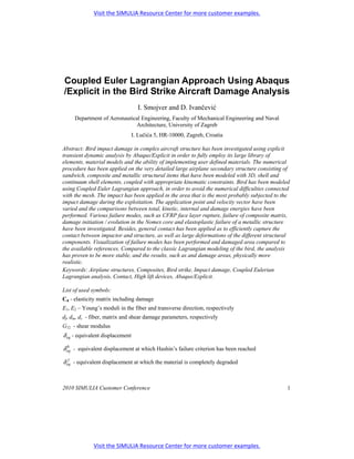
  • 5. parameters, which modify the initial undamaged elasticity matrix. Fiber (df), matrix (dm) and shear (ds) damage parameters reflect the current state of damage, having values ranging from 0 for an undamaged state, to 1 for a completely degraded material. The damaged elasticity matrix has the form  ( ) 1 − d f E1 (1 − d f )(1 − d m )ν 21E1 0  Cd = 1 D ( ) 1 − d f (1 − d m ) 12 E 2 ν (1 − d m )E2 0  (1)    0 0 (1 − d s )G12 D   where D = 1 − (1 − d f )(1 − d m )ν 12ν 21 . E1 , E 2 , G12 , ν 12 , and ν 21 are unidirectional ply material properties. Figure 2. Equivalent stress-displacement diagram (left-hand image) and damage variable as a function of equivalent displacement (right-hand image) To avoid mesh dependency during material softening, Abaqus uses a constitutive law expressed as a stress - equivalent displacement relation. Linear elastic behavior prior to damage initiation is represented by the positive slope (OA) of the stress-displacement curve in Figure 2, left-hand image. When Hashin’s damage initiation criterion is reached, damage parameters modify the stiffness matrix thereby simulating degradation of mechanical properties. This part of stress – equivalent displacement curve is represented by the negative slope curve (AC) on Figure 2, left- hand image. Unloading and reloading from a partially damaged state occurs along a linear path toward the origin represented by the BO (or OB for reloading) path. The area of the triangle OAC is equal to the energy dissipated due to damage. After damage initiation, damage parameter of a particular failure mode evolves as δ eq (δ eq − δ eq ) f 0 d= ( δ eq δ eq − δ eq f 0 ), (2) 2010 SIMULIA Customer Conference 5
  • 6. where δ eq is the initial equivalent displacement at which Hashin's damage initiation criterion was 0 reached and δ eq is the displacement at which the material is completely damaged in this failure f mode. Equation (2) is graphically presented on Figure 2, right-hand image. An element is removed from the mesh when all material points reach the critical degradation value. The use of the composite damage model in these particular impact problems has been validated in (Smojver, 2009). Mechanical properties of Aluminum alloys have been taken from (MIL-HDBK-5, 1998). Failure of metallic structural items has been modeled by shear failure criterion. The shear failure criterion is suitable for high strain rate dynamic problems and is based on the accumulated equivalent plastic strain, which is calculated as t ∫ 2 pl pl ε pl = ε 0pl + ε : ε dt , (3)   3 0 where ε 0 is the initial value of equivalent plastic strain and ε is the equivalent plastic strain pl  pl rate. An element is assumed to fail when the damage parameter calculated as ε 0pl + ∑ ∆ε pl ω= (4) ε fpl pl exceeds the value 1. In Equation (4) ε f is the strain at failure, ∆ε pl is the plastic strain increment and the summation is performed over all increments in the analysis. Figure 3. Compressive stress-strain curve of Nomex honeycomb core (Meo, 2003). Characteristic behavior of Nomex honeycomb cores under compressive loads is shown on Figure 3. The first region corresponds to a linearly elastic region which is present at low strains (typically 0.5-5%). The next step is progressive core crushing at a nearly constant stress level called the 6 2010 SIMULIA Customer Conference
  • 7. plateau stress ( σ pl ). At a strain value of about 85% a region of increasing stresses caused by mutual pressing of cell walls. To simulate core crushing the above explained shear failure criterion was adopted to remove core finite elements from the mesh when a equivalent plastic strain of 5% is reached. The Yield stress value is assumed to be 7.76MPa as stated in (Meo, 2003). 2.3 Coupled Eulerian Lagrangian (CEL) bird model The finite element mesh in CEL analyses usually represents a stationary cube through which the Eulerian material moves and impacts on the Lagrangian structure. Abaqus provides EC3D8R elements to model Eulerian problems, which may be completely or partially filled by bird material while the rest of the Eulerian grid is filled with void material. The material is tracked as it flows through the mesh by means of Eulerian volume fractions (EVF) which represent the ratios by which each Eulerian element is filled with material. If the volume fraction is one, the element is completely filled with material, contrary to the completely void elements that take volume fractions equal to zero. The Eulerian material boundary doesn't have to match element geometry at any time in the analysis and has to be recomputed in each time increment as the material flows through the mesh. Abaqus/CAE provides the volume fraction tool which enables user friendly initial calculation of volume fractions thereby enabling "filling" of Eulerian elements with bird material. The volume fraction tool also creates a node set containing nodes in the area of the bird reference part allowing assignment of initial conditions to the bird material. Dimensions of the grid containing Eulerian elements must be sufficiently large to prevent loss of bird material after the impact. The loss of material leads to a loss of kinetic energy and can sometimes lead to numerical difficulties which decrease the level of confidence in the obtained results. Typical assumptions used in finite element bird strike simulations have been employed in this paper as well. The bird geometry has been replaced with a cylinder having hemispherical ends and a length to radius ratio equal to two, as this geometry best resembles pressure time histories of real birds during impact tests, as stated in e.g. (Airoldi, 2006). Bird material has been replaced with an equal mass of water, as birds mostly consist of water and air trapped in the bones and lungs. To take the trapped air into account the density has been reduced to 938 kg/m3, as suggested in (Johnson, 2003). The Us-Up Equation of state material model has been used to model the bird, while the properties for the Mie-Grueneisen EOS for water have been taken from (Chizari, 2009). Validation of the used bird material model in an impact on a rigid plate showed good agreement with theoretical and experimental Hugoniot and stagnation pressure time history curves, as demonstrated in (Smojver, 2010). 2.4 Comparison of Lagrangian and CEL bird models The CEL bird model presented in this work has been validated by comparison with experimental results presented in (Welsh, 1986). The results presented in this reference evaluate the eligibility of substitute gelatin birds as bird replacements in gas gun experiments, as impact tests including real birds are hard to replicate due to the heterogeneity of real birds. Impactors including both real and artificial birds, having weights of 4 lb (1.81 kg), were fired against Aluminum Al 6061 T6 plates at speeds of approximately 150 m/s. The dimensions of the target plate are 550 x 550 x 6.35 mm. The impacted plate is bolted to a steel support plate with the 0.4064 m diameter opening. The Aluminum plate is discretisized by 520 S4R shell elements, as shown in Figure 4. The steel support frame has been replaced by boundary conditions as the nodes outside the 0.4064 m diameter opening had restrained displacements in the thickness direction. Additionally six nodes 2010 SIMULIA Customer Conference 7
  • 8. had all six degrees of freedom restricted as to take into account the effect of the bolts. The mechanical properties of Al 6061 T6 were taken from (MIL-HDBK-5, 1998) while the strain rate effects were ignored. Dimensions of the Eulerian part are 1.4 x 1.4 x 0.5 m to ensure that the bird material doesn't protrude outside the Eulerian finite element grid consisting of 980000 elements. Figure 4. Target plate FE model (left-hand image) and CEL model (right-hand image). Figure 5. Comparison of plate deflections [mm]. Figure 6. Comparison of deformed plate shapes [mm]. 8 2010 SIMULIA Customer Conference
  • 9. To demonstrate the advantages of the Eulerian bird modeling approach this experiment has also been numerically modeled using the Lagrangian bird model presented in (Smojver, 2010). The results of the analyses are shown on Figures 5 and 6. The measured deflection at the center of the impacted plate in the gas gun experiment at the impact speed of 145.7 m/s is 41.3 mm. The deflections calculated numerically were 40.7 mm for the Lagrangian and 38.54 mm for the CEL bird model. Although the result for the Lagrangian bird model was closer to the value obtained by gas gun tests, the distribution of plate deflections and the deformed plate shape after impact are more realistic, as shown on Figures 5 and 6. The improved similarity of impacted plate shape is a direct result of the physically enhanced modeling of fluid-like bird behavior by the CEL bird model. The stability of the analysis is also improved as the CEL bird model doesn't suffer from significant mesh distortion. The main disadvantage of the CEL model, compared to the Lagrangian bird model, is the highly prolonged computational time due to the need for a very fine mesh of Eulerian elements to accurately simulate the contact with the Lagrangian mesh. 3. Substructure approach The substructure approach presented in (Smojver, 2010) has been further developed in order to include modeling of CEL analysis. As nonlinear transient analyses on large and complex models demand enormous computation time, despite the usage of most modern computers, bird impact damage prediction analyses could be accurately performed on smaller parts of aeronautical structures. This assumption is based on the fact that impact induced damage is localized to the area in the vicinity of the impact location. For the purpose of model reduction, a C# routine has been developed which removes parts of the finite element mesh which are further away from the impact location. The cutting distance is user defined and measured from the assumed impact location what enables the creation of arbitrary model sizes. The C# routine allows optional choice between the Lagrangian and the CEL bird model. If the Coupled Eulerian Lagrangian approach is selected, a Python script has been developed which creates an input file for the Eulerian part instance. Definition of the bird is done by an automated procedure which enables creation of arbitrary sized Eulerian parts having adjustable dimensions, mesh sizes and properties for the EOS material. The bird geometry is defined by entering height and radius of the cylinder with hemispherical tip, which contains the Eulerian bird material. Using these input variables the python script launches Abaqus/CAE and creates the Eulerian part together with the bird reference geometry. The next step is the creation of the assembly which is built based on the location of the impacted node and defined flight conditions of the airplane. The Eulerian part is translated so that the impacted node is positioned at the centre of the grid of Eulerian elements while the bird geometry is translated and rotated to take into account the flight conditions during impact. An additional translational variable is defined to prevent initial overclosure between the Larangian mesh and Eulerian bird material. After repositioning of the Eulerian mesh and bird geometry the volume fraction tool is launched to create the volume fractions needed to define the material boundary. Based on these actions, an input file is written which is then combined by the C# routine with the substructure input file to create the final input file for the analysis. This procedure enables a user friendly generation of input files, hence eliminating the usage of the Abaqus pre-processor and the time demanding procedure of manual creation of smaller CEL models. Figure 7 depicts the substructure model used for impact analyses in this particular case, 2010 SIMULIA Customer Conference 9
  • 10. where the complete model has been reduced to 48979 elements. The grid of Eulerian elements consists of 753571 elements. Figure 7. CEL model for the impact on the substructure (left-hand image) and finite element mesh of the substructure (right-hand image). 4. Analysis The CEL bird strike damage prediction capability has been demonstrated in a simulation of a typical bird strike event on an inboard flap. The point of impact and bird velocity vector have been chosen according to the landing flight variables of a large transport aircraft. The aircraft angle of attack (10°) and flight path glide slope of 5° have been summed to the maximum flap deflection angle (40°) resulting in a velocity vector deflected 55° with regard to the horizontal plane of the flap model. The flight velocity of the aircraft during the impact has been assumed to be 100 m/s, while the bird velocity has been neglected. The impacting forces and pressures exerted during the impact are transferred to the flap model by use of contact algorithms. Abaqus provides an extension of the general contact option to include interactions between Lagrangian structures and Eulerian material. The contact is created between Lagrangian mesh surfaces and Eulerian meterial surfaces, which are automatically computed and tracked during the analysis. A very fine mesh of Eulerian grid is necessary to efficiently capture the contact between those two surfaces. Abaqus, like most of the commercial FE codes, uses penalty contact algorithms to introduce coupling between Eulerian and Lagrangian instances, as this approach uses the simplest computational level and gives great robustness as described in (Benson, 2004). 10 2010 SIMULIA Customer Conference
  • 11. Figure 8. CEL model of 1.81 kg bird. 5. Results To demonstrate the bird strike damage prediction capability of CEL analyses presented in this paper, two impact scenarios have been chosen. The first impact case involves an impact of a 4 lb (1.81 kg) bird, since flap structures of large transport aircraft have to withstand an impact of this bird weight at normal operating speeds, as defined in FAR 25.571. The analysis has been performed on the complete flap finite element model. Figure 8 shows the location of the Eulerian grid and the initial position of bird material with regard to the flap model. The Eulerian part used in this analysis contains 600000 elements enclosing a volume having dimensions 1x 1 x 0.6m. The composite skin in the area of the impact has 20 CFRP layers with the total thickness of 2.5 mm. Figure 9. Deformation of 1.81 kg bird during the impact (EVF= 0.5) 2010 SIMULIA Customer Conference 11
  • 12. The impact event is shown on Figure 9. As illustrated, the kinetic energy of a 1.81 bird kg at the impacting speed of 100 m/s is sufficient to cause severe damage on the flap. The bird penetrates the lower flap skin and impacts on the upper skin. The dominant failure modes of the composite flap skins are tensile fiber and matrix failure, as illustrated on Figure 10. One of the certification requirements defined in FAR 25.571 states that the safety of the aircraft must not be threatened by the damage caused by bird strikes. Although the impact in this case resulted in complete failure of the lower skin and serious damage of the upper skin, the main load carrying structural items were not affected by the impact. The next step in the investigation of compliance with certification requirements would be to simulate the effect of aerodynamic loads on the impacted flap structure, which is the subject of ongoing research. The second impact scenario involves a 0.45 kg bird, as collisions with smaller birds, like crows, are much more frequent. This analysis has been performed on the substructure model shown on Figure 7. The impact event is shown on Figure 11. The impacted lower skin in this case is able to withstand the bird strike, although some elements have been removed from the mesh. These elements have reached the critical degradation values for the damage evolution model as described in chapter 2.2 for all section points of the element and are therefore excluded from the analysis. Figure 12 shows the distribution of Hashin's failure criteria values of lower skin and stringers. Despite the fact that that only two elements have failed completely, the relatively large area affected by the matrix cracks is susceptible for delamination growing and has therefore to be repaired accordingly. Figure 10. Contour plots of Hashin's failure criterions of lower flap skin (cross- sectional view) at an impact of a 1.81 kg bird 12 2010 SIMULIA Customer Conference
  • 13. Figure 11. Impact of a 0.45 kg bird on the substructure model (EVF=0.5). Figure 12. Contour plots of Hashin's failure criterions of lower flap skin and stringers (upper skin removed) at an impact of a 0.45 kg bird. 2010 SIMULIA Customer Conference 13
  • 14. 6. Conclusions This work presents the improvements of the bird strike damage prediction procedure presented in (Smojver, 2010). The main improvement is done in the modeling of the physical behavior of the bird during the impact by replacing the Lagrangian bird model with the CEL bird model. The CEL bird model also improves the stability of the transient dynamic explicit analysis, as numerical problems associated with mesh distortion are not present. The physically improved modeling of the fluid-like bird behavior also results in more realistic behavior of the impacted structure. The main drawback of CEL analyses is the increase of computational time which for the analyses presented in this work, depending on the number of Eulerian elements, exceeds 24 hours on a workstation with two processors with 4 cores each. The comparable Lagrangian analyses on the complete flap model took about 8 hours of computational time. 7. References 1. Abaqus Analysis User Manual, Version 6.8. Dassault Systémes, 2008. 2. Airoldi, A., and B. Cacchione, "Modelling of Impact Forces and Pressures in Lagrangian Bird Strike Analyses," International Journal of Impact Engineering, no. 32, pp.1651-1677, 2006. 3. Benson, D.J., and S. Okuzawa, "Contact in a Multi-Material Eulerian Finite Element Formulation," Computer Methods in Applied Mechanics and Engineering, no. 193, pp. 4277- 4298, 2004. 4. Chizari, M., L.M. Barrett and S.T.S Al-Hassani, "An Explicit Numerical Modelling of the Water Jet Tube Forming," Computational Materials Science, no. 45, pp. 378-384, 2009. 5. Lavoie, M.A., A. Gakwaya,M. Nejad Ensan and D.G. Zimcik, "Review of Existing Numerical Methods and Validation Procedure Available for Bird Strike Modelling," International Conference on Computational & Experimental Engineering and Sciences, pp.111-118, 2007. 6. Meo, M., R. Vignjević and M. Maengo, "Numerical Simulations of Low-Velocity Impact on an Aircraft Sandwich Panel," Composite Structures no.62, pp. 353–360, 2003. 7. Metallic Materials and Elements for Aerospace Vehicle Structures, MIL-HDBK-5J. Department of Defense Handbook. Washington, DC, 2003. 8. Rueda, F., F. Beltran, C. Maderuelo and H. Climent, "Birdstrike Analysis of the Wing Slats of EF-2000," 2002. 9. Smojver, I. and D. Ivancevic, "Numerical Simulation of Bird Strike Damage Prediction in Airplane Flap Structure," Composite Structures, article in press, 2010. 10. Welsh C.J. and V. Centoze, "Aircraft Transparency Testing - Artificial Birds," Arnold Engineering Development Center, Report AEDC-TR-86-2, 1986. 8. Acknowledgment This research has been financially supported by the Ministry of Science, Education and Sports, Republic of Croatia through Technology Project TP-07 / 0120 – 30 and the scientific project “Numerical Modelling of Nonisotropic Continua”. The authors would also like to express their gratitude to Mr. Dario Mihaljević, Dipl. AE, who developed the C# code used in the creation of substructures. 14 2010 SIMULIA Customer Conference Visit the SIMULIA Resource Center for more customer examples.