Downloaded 128 times
![INTERNATIONAL Mechanical Engineering and Technology (IJMET), ISSN 0976 –
International Journal of JOURNAL OF MECHANICAL ENGINEERING
6340(Print), ISSN 0976 – 6359(Online) Volume 3, Issue 3, Sep- Dec (2012) © IAEME
AND TECHNOLOGY (IJMET)
ISSN 0976 – 6340 (Print)
ISSN 0976 – 6359 (Online)
IJMET
Volume 3, Issue 3, September - December (2012), pp. 429-437
© IAEME: www.iaeme.com/ijmet.asp ©IAEME
Journal Impact Factor (2012): 3.8071 (Calculated by GISI)
www.jifactor.com
STRESS ANALYSIS AND OPTIMIZATION OF CRANKSHAFT UNDER
DYNAMIC LOADING
1 2
Imran M Quraishi Mrs. Madhuvi S Harne
ME (Mechanical Design) Professor (Mechanical Design)
Govt. College of Engineering, Aurangabad (MS) Govt. College of Engineering, Aurangabad
(imranquraishi@rediffmail.com) (msharne11@gmail.com)
ABSTRACT
In this study a dynamic simulation was conducted on a forged steel crankshaft from a single cylinder
four stroke engine. Finite element analysis was performed to obtain the variation in the magnitude of
the stress at critical locations. The dynamic analysis resulted in the development of theload spectrum
applied to the crankpin bearing. This load was then applied to the FE model and boundary conditions
were applied according to the engine mounting conditions. Results obtained from the analysis were
then used in optimization of the forged steel crankshaft. Geometry, material, and manufacturing
processes were optimized using different geometric constraints, manufacturing feasibility, and cost.
The first step in the optimization process was weight reduction of the component considering
dynamicloading. This required the stress range under dynamic loading not to exceed the magnitude
of the stress range in the original crankshaft. The optimization and weight reduction were considered
in aninteractive manner and evaluated by manufacturing feasibility and cost. The optimization
process resulted in weight reduction, cost reduction and increased fatigue strength of the crankshaft.
INTRODUCTION
The crankshaft is one of the largest components in the internal combustion (IC) engine and has a
complex geometry consisting of cylinders as bearings, and plates as the crank webs. Geometry section
changes in the crankshaft cause stress concentration at fillet areas where bearings are connected to the
crank webs. In addition, this component undergoes both torsional and bending loads during its service
life. Therefore, fillet areas are locations that are subject to the most critical stresses during the service
life of the crankshaft. As a result, these locations are a common fatigue failure site of crankshafts.
Since the crankshaft has a complex geometry for analysis, finite element models have been considered
to provide an accurate and reasonable simulation. Because crankshafts are among large volume
production components in the IC engine, weight and cost reductions of this component are very
effective in increasing the fuel efficiency and reducing the overall cost of the engine.
Since fatigue crack initiation and fracture at the fillets is one of the primary failure
mechanisms of automotive crankshafts, the fillet rolling process has been used to improve the fatigue
life of crankshafts for many years. The fillet rolling process induces compressive residual stresses
within the fillet surface. The compressive residual stress lowers the fatigue driving forces due to
operating loads near the fillet surface and consequently increases the fatigue life of the crankshaft.
Kamimura (1985) [1] performed a study on the effect of fillet rolling on fatigue strength of a ductile
429](https://image.slidesharecdn.com/stressanalysisandoptimizationofcrankshaftunderdynamicloading-2-121218004708-phpapp01/75/Stress-analysis-and-optimization-of-crankshaft-under-dynamic-loading-2-1-2048.jpg)
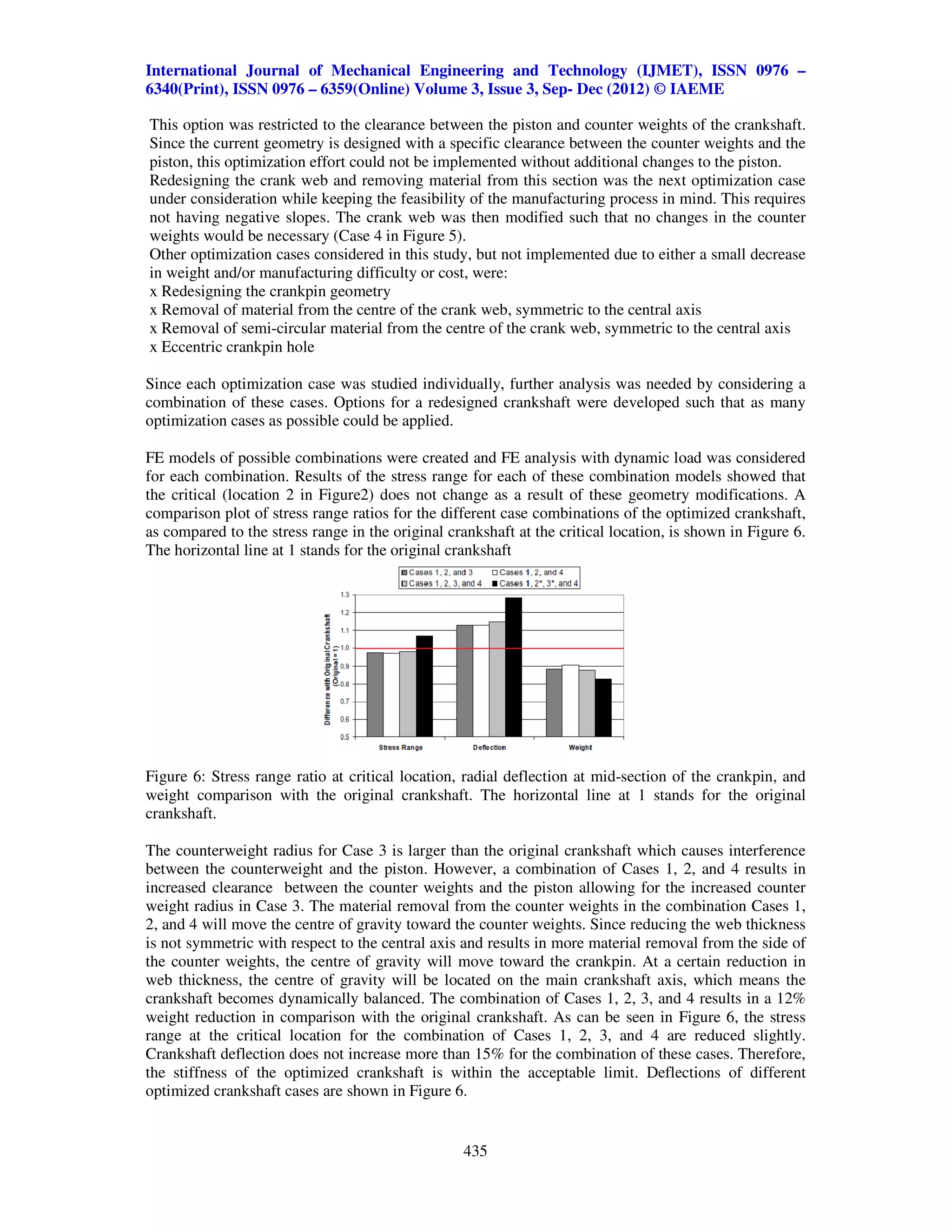
![International Journal of Mechanical Engineering and Technology (IJMET), ISSN 0976 –
6340(Print), ISSN 0976 – 6359(Online) Volume 3, Issue 3, Sep- Dec (2012) © IAEME
cast iron crankshaft. Bench tests were conducted on crankshaft pin samples with a fatigue evaluation
on test pieces in order to study the fatigue strength of fillet rolled crankshafts and specimens. This
study showed that an optimum deep rolling method could increase the bending fatigue strength by
83% over conventional ductile iron crankshafts that were not fillet rolled.
Park et al. (2001) [2] showed that without any dimensional modification, the fatigue life of a
crankshaft could be improved significantly by applying various surface treatments. Fillet rolling and
nitriding were the surface treatment processes that were studied in this research. Their study showed
that the standard base sample had a fatigue limit of 10 kN, while fillet rolled specimens with 500 kgf
load exhibited a 14 kN fatigue limit (i.e. 40% increase in fatigue limit). With 900 kgf rolling load, the
fatigue limit increased to more than 18KN (i.e.80% increase in fatigue limit). These experimental data
clearly indicate that fillet rolling can dramatically increase the fatigue performance of crankshafts.
Although higher rolling force results in better fatigue strength as a result of inducing higher
compressive stress on the fillet surface, the load should not be so high as to cause excess plastic
deformation. The specimens prepared from the crankshaft in the Park et al. study found the optimum
level of rolling force as experimentally to be between 700kgf and 900 kgf.
An extensive study was performed by Nallicheri et al. on material alternatives for the automotive
crankshaft based on manufacturing economics [3]. Steel forgings, nodular cast iron, micro-alloy steel
forgings, and austempered ductile iron (ADI) casting were considered as manufacturing options to
evaluate the cost effectiveness of using these alternatives for crankshafts. It was concluded that the
production volume of the crankshaft and the requirements of the engine were predominant factors in
a cost effective production option for this application. The selection of the best alternative is
dependent upon the production volume. At production volumes above 200,000 parts/year,
microalloyed steel forgings offered the most cost effective high performance crankshaft.
The ADI crankshafts were cost effective at low production runs (below1,80,000 parts/year). Based on
these assumptions, raw material was about 30% of the final cost, whereas machining cost was 47%
for the forged steel crankshaft. The raw material cost of the microalloyed steel forging crankshaft was
38%, but the machining percentage cost was 43% which reduced the cost of the final component. In
addition, the heat treatment process was eliminated for the microalloyed steel crankshaft, resulting in
a further cost reduction.
A study was performed by Hoffmann and Turonek to examine the cost reduction opportunities
associated with forged steel in which the raw material and machinability were the primary factors
evaluated [4]. Materials evaluated in their study included medium carbon steel SAE 1050 (CS) and
medium carbon alloy steel SAE 4140 (AS) grades using a sulphur level of 0.10%, (CS-HS and AS-
HS), and two micro-alloy grades (MA1 and A2). The material selection was based on fatigue strength
requirements and potential cost benefits. The microalloy grades that were evaluated offered cost
reduction opportunities over the original materials. The micro-alloy grade could reduce the finished
cost by 11% to 19% compared to a quenched and tempered alloy steel (SAE 4140), and by 7% to
11% compared to a quenched and tempered carbon steel (SAE 1050). In addition, the micro-alloy
grades met or exceeded the fatigue strength of the original materials for the applications studied and
had better machinability characteristics.
Detailed dynamic load and stress analysis of the crankshaft investigated in this study by
Montazersadgh F. H. and Fatemi Ali [5]. Finite element analysis was used to obtain the variation in
stress magnitude at critical locations. The dynamics of the mechanism was solved using analytical
techniques and the results were verified by simulation in ANSYS, which resulted in the load
spectrum applied to the crank pin bearing. The load was applied to the FE model, and the boundary
conditions were defined according to the engine mount design. The analysis was performed over
different engine speeds and as a result the critical engine speed and critical locations on the
crankshaft were obtained. Stress variation over the engine cycle and the effect of torsional load in the
analysis were also investigated. Results from FE analysis were verified by attaching strain gages to
several locations on the crankshaft [5].
430](https://image.slidesharecdn.com/stressanalysisandoptimizationofcrankshaftunderdynamicloading-2-121218004708-phpapp01/75/Stress-analysis-and-optimization-of-crankshaft-under-dynamic-loading-2-2-2048.jpg)
![International Journal of Mechanical Engineering and Technology (IJMET), ISSN 0976 –
6340(Print), ISSN 0976 – 6359(Online) Volume 3, Issue 3, Sep- Dec (2012) © IAEME
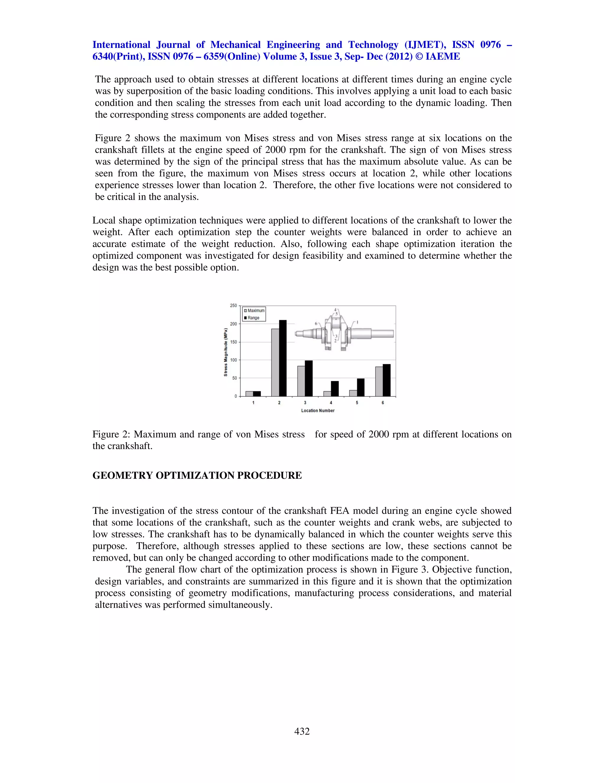
The optimization carried out in this work was not based on only the typical geometrical optimization
techniques. This is because variables such as manufacturing and material parameters could not be
organized in a mathematical function according to the set of constraints such that the maximum or
minimum could be defined. Instead, each optimization step was approximated based on improving
fatigue resistance while considering manufacturing feasibility and maintaining dynamic balance with
an aim of reducing the weight and the final cost of the component.
In this paper, a brief summary of the dynamic loading and stress analysis of the forged steel
crankshaft is first considered with details provided in [5]. Then the optimization objectives,
constraints, and procedure that have been used are described. This is followed by a discussion of
material alternatives and the application of compressive residual stress in the fillet area of the
crankpin. Finally, a brief discussion of cost reduction of the optimized crankshaft is provided.
DYNAMIC LOAD AND STRESS ANALYSIS
The crankshaft is subjected to complex loading due to the motion of the connecting rod, which
transforms two sources of loading, namely combustion and inertia, to the crankshaft. Optimization of
the crankshaft requires a determination of an accurate assessment of the loading, which consists of
bending and torsion. Dynamic loading analysis of the crankshaft results in more realistic stresses
whereas static analysis provides results that may not reflect operating conditions. Accurate assessment
of stresses is critical to the input of fatigue analysis and optimization of the crankshaft design.
Figure 1 shows the digitized model of the forged steel crankshaft used in this study. The dynamic
analysis of the engine that uses this type of crankshaft showed that as the engine speed increases the
maximum bending load decreases. Therefore, the critical loading case for this engine is at the
minimum operating speed of 2000 rpm [5]. This should not be misunderstood as to mean that the
higher the engine rpm is the longer the service life because there are many other factors to consider in
operation of the engine. The most important issue when the engine speed increases is wear and
lubrication. As these issues were not considered in the dynamic load analysis study, Further
discussion of these issues is avoided.
It was also shown that a consideration of the torsional load in the overall dynamic loading conditions
has no effect on von Mises stress at the critically stressed location [5]. In addition, the effect of torsion
on the stress range is also relatively small at other locations undergoing torsional load. Therefore, the
crankshaft analysis could be simplified to an application of bending load only [5].
Figure 1: Digitized model of the original forged steel Crankshaft geometry used.
Convergence of stress at different locations was considered as the criterion for the selection of mesh
size and number of elements for the finite element stress analysis. Satisfactory results were obtained
using 119,337 elements for the crankshaft that corresponded to a global mesh size of 5.08 mm and a
local mesh size of 0.762 mm in the model. This local mesh size resulted in five elements in the radius
of the fillet areas.
431](https://image.slidesharecdn.com/stressanalysisandoptimizationofcrankshaftunderdynamicloading-2-121218004708-phpapp01/75/Stress-analysis-and-optimization-of-crankshaft-under-dynamic-loading-2-3-2048.jpg)
![International Journal of Mechanical Engineering and Technology (IJMET), ISSN 0976 –
6340(Print), ISSN 0976 – 6359(Online) Volume 3, Issue 3, Sep- Dec (2012) © IAEME
FILLET ROLLING AND MATERIAL ALTERNATIVES
The next step in the optimization process was an attempt to modify the production steps in order to
reduce the cost or improve the performance of the original crankshaft. Further improvement of the
performance could result in further geometry changes and weight reduction. A potential modification
for this improvement and subsequent weight reduction is the addition of compressive residual stress
to the fillet area of the crankpin which is the critical (i.e. failure) area.
Due to lack of experimental information, the precise magnitude of the residual stress that could be
induced in the crankshaft geometry under investigation could not be determined. Studies by
Kamimura [1], Park et al. [2], and Chien et al. [6] showed that inducing compressive residual stress
increases the fatigue strength of the crankshaft significantly. Based on these studies, the application
of compressive residual stress in the fillet area of the crankshaft can increases the fatigue strength by
40% to 80%, depending on the material properties, crankshaft geometry, and the applied rolling
force.
With regard to material options, one of the most common alternatives for forged steel is microalloyed
(MA) steel. Pichard et al. [7] performed a study on modified microalloyed steel with a titanium
addition for the production of forged crankshafts. The use of MA steel enables elimination of any
further post-forging heat treatment, resulting in shorter manufacturing process with a subsequent
increase in the forged crankshaft productivity. The choice of this MA steel for a crankshaft
application was based on the 35MV7 steel grade, with a typical composition of 0.35C, 1.8Mn, 0.25Si,
0.12V with an addition of the microalloying element Ti. Based on the results of their study, the
35MV7 control-cooled microalloyed steel showed similar tensile and rotating bending fatigue
behaviour to AISI 4142 quenched and tempered steel. In addition, the machinability of the
microalloyed steel could be improved by about 40% in turning and about 160% in drilling [7].
Therefore, the use of microalloyed steel can reduce the final cost of the crankshaft by eliminating the
heat treatment process and increasing machinability.
FINAL OPTIMIZED CRANKSHAFT
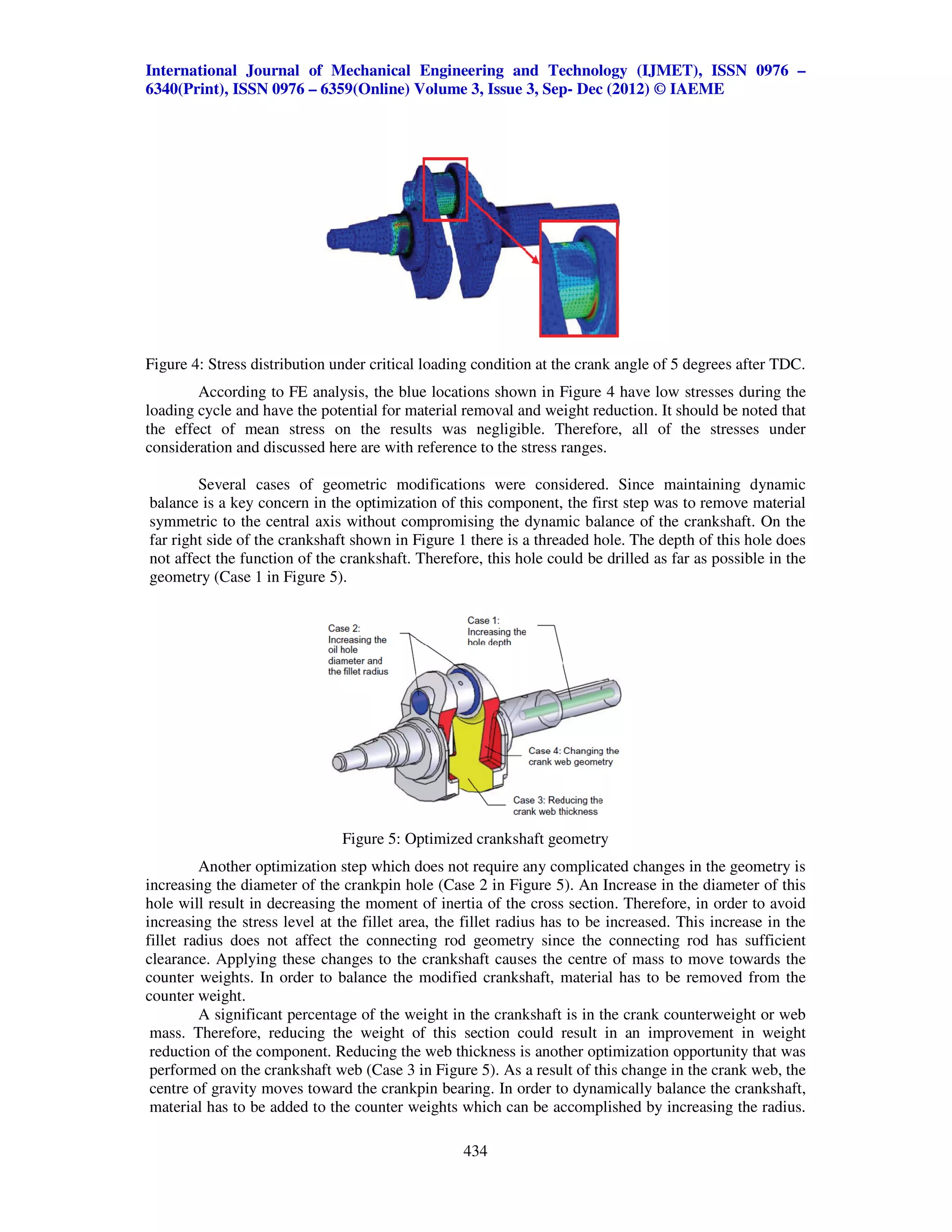
Considering the manufacturing processes, the geometry of the crankshaft could be modified further to
take advantage of the results of improved fatigue strength due to fillet rolling and/or the use of
microalloyed steel. Further modification to the crankpin geometry is possible. Increasing the crankpin
hole is an option which does not influence the manufacturing process and is not an expensive process.
Increasing the hole diameter from the original 18.3 mm (0.72 inch) to 25.4 mm (1 inch) and reducing
the crank web thickness in order to maintain dynamic balance of the crankshaft, will cause the stress
range at the critical location to increase by 7%. This increase is easily compensated for by the
beneficial effect of the compressive residual stress from fillet rolling. This modification is shown as
Case 1, 2, 3, and 4 in Figure 6. Since the wall thickness in the crankpin area is limited, further
increasing the hole diameter to larger than 25.4 mm was not possible, because sufficient material is
needed to restrict plastic deformation in the rolling process to produce residual stress. These
modifications reduce the weight of the original crankshaft by 18%. The final optimized geometry is
shown in Figure 5. It should be noted that the fatigue strength of the optimized crankshaft is
significantly higher than the original crankshaft due to a slight increase in the stress range of 7% at the
fillet and a significant increase on the order of 40% to 80% in fatigue strength due to fillet rolling, as
discussed earlier. Figure 7 shows the stress range comparisons at different locations shown in Figure
2, between the original and the optimized crankshafts. As can be seen in this figure, the critical
location is still at the fillet and the increase in stress at other locations is not significant.
With regard to the cost of the optimized crankshaft, this is affected by the geometry changes
and weight reduction, modification in the manufacturing process, and the use of MA steel. The
optimized geometry requires redesign and remanufacturing of the forging dies used. The geometry
parameters that influence machining and the final cost of the component include an increase in the
drilling process. This is because the drilled holes in Cases 1 and 2 are redesigned to have larger
436](https://image.slidesharecdn.com/stressanalysisandoptimizationofcrankshaftunderdynamicloading-2-121218004708-phpapp01/75/Stress-analysis-and-optimization-of-crankshaft-under-dynamic-loading-2-8-2048.jpg)
![International Journal of Mechanical Engineering and Technology (IJMET), ISSN 0976 –
6340(Print), ISSN 0976 – 6359(Online) Volume 3, Issue 3, Sep- Dec (2012) © IAEME
diameters and the bore in Case 1 is modified to have more depth than the original bore. The
application of compressive residual stress by a fillet rolling process is a parameter in the
manufacturing process that will add to the cost of the finished component.
Although a microalloy steel grade is somewhat more expensive than hot-rolled steel bar, the
heat treatment cost savings are significant enough to offset this difference (Wicklund, 2007 [8]). In
addition, microalloyed steel has 5% to 10% better machinability than quenched and tempered steel,
resulting in reduced machining costs due to enhanced production rates and longer tool life (Nallicheri
et al. [3]). A consideration of these factors, along with the reduced material cost due to the weight
reduction, indicates a reduction in the total cost of the forged steel crankshaft.
SUMMARY
An optimization study was performed on a forged steel crankshaft that considered the
geometry, performance, manufacturing process, and cost. A major constraint of this optimization was
for the optimized crankshaft to replace the original crankshaft in the engine without any changes to
the engine block or the connecting rod. An optimization in the geometry included local changes at
different locations on the crankshaft, which were then combined to obtain the final optimized
geometry.
Adding fillet rolling was considered in the manufacturing process. Fillet rolling induces
compressive residual stress in the fillet areas, which results in a significant increase in fatigue strength
of the crankshaft, and in turn, significantly increases the fatigue life of the component. The use of a
microalloyed steel as an alternative material to the current forged steel composition results in the
elimination of the heat treatment process. In addition, when considering the improvement in
machinability of the microalloyed steel along with the reduced material cost because of an 18%
weight reduction, the overall cost of the forged steel crankshaft can be reduced.
The optimization resulted in weight reduction of the forged steel crankshaft. This was
achieved by changing the dimensions and geometry of the crank counterweights while maintaining
dynamic balance of the crankshaft. The optimization that was developed did not require any changes
to the engine block or connecting rod.
REFERENCES
1. Kamimura, T., 1985, “Effects of Fillet Rolling on Fatigue Strength of Ductile Cast Iron
Crankshaft,”SAE Technical Paper No. 852204, Society of Automotive Engineers, Warrendale, PA,
USA.
2. Park, H., Ko, Y. S., and Jung, S. C., 2001, “Fatigue Life Analysis of Crankshaft at Various Surface
Treatments,” SAE Technical Paper No. 2001-01-3374, Society of Automotive Engineers,
Warrendale, PA, USA.
3. Nallicheri, N. V., Clark, J. P., and Field, F. R., 1991, “Material Alternatives for the Automotive
Crankshaft; A Competitive Assessment Based on Manufacturing Economics,” SAE Technical
Paper No. 910139, Society of Automotive Engineers, Warrendale, PA, USA.
4. Hoffmann, J. H. and Turonek, R. J., 1992, “High Performance Forged Steel Crankshafts – Cost
Reduction Opportunities,” SAE Technical Paper No. 920784, Society of Automotive Engineers,
Warrendale, PA, USA.
5. Montazersadgh, F. H. and Fatemi, A., 2007, “Dynamic Load and Stress Analysis of a Crankshaft,”
SAE Technical Paper No. 2007-01- 0258, Society of Automotive Engineers, Warrendale, PA, USA.
6. Chien, W. Y., Pan, J., Close, D., and Ho, S., 2005, “Fatigue Analysis of Crankshaft Sections Under
Bending with Consideration of Residual Stresses,”
International Journal of Fatigue, Vol. 27, pp. 1-19.
7. Pichard, C., Tomme, C., and Rezel, D., 1993, “Alternative Materials for the Manufacture of
Automobile Components: Example of Industrial Development of a Microalloyed Engineering Steel
for the Production of Forged Crankshafts,” In Proceedingsof the 26th ISATA International
Symposium on AutomotiveTechnologyand Automation, pp. 157-163, Aachen, Germany.
8. Wicklund, M. A., 2007, Private Communication in Feb. 2007.
437](https://image.slidesharecdn.com/stressanalysisandoptimizationofcrankshaftunderdynamicloading-2-121218004708-phpapp01/75/Stress-analysis-and-optimization-of-crankshaft-under-dynamic-loading-2-9-2048.jpg)

This document summarizes a study that optimized the design of a forged steel crankshaft through finite element analysis and stress modeling. The analysis found the crankshaft experiences maximum stress at location 2. Geometry optimization focused on removing non-critical material while maintaining dynamic balance. Optimization included increasing hole diameters, deepening holes, and modifying crank web geometry. The goal was reducing weight and cost while not exceeding the original design's stress levels. Material choices and compressive rolling were also evaluated for increasing fatigue strength.