Deep foundations outline
•Introduction
• Types of deep foundations
• Types of piles
• Design of piles
• Settlement of piles
• Pile groups
• Pile testing
2
3.
Deep foundations
• Adeep foundation is a type of foundation which transfers structural loads at
a greater depth below the ground surface.
• They are used when:
i. When the soil is very soft and solid bed is not available at a reasonable
depth to keep the bearing power within safe limits.
ii. When provision of pad and raft foundations becomes very expensive.
iii. When the structure carries heavy concentrated loads.
iv. When it is necessary to construct a building along the sea-shore or river
bed.
3
4.
Conditions that requiredeep foundations
v. Very large vertical loads with respect to the soil capacity
vi. Very weak soil or problematic soil
vii. Huge lateral loads (earth retaining structures. Tall buildings,
basements)
viii. Scour depth criteria (bridges)
ix. Uplift situations (transmission towers, offshore platforms, basement
mats)
x. For fills having very large depths
xi. Urban areas for future construction near existing buildings.
4
5.
Types of deepfoundations
• There are three main types of deep foundations:
i. Piers
ii. Caissons
iii. Piles
5
6.
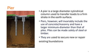
Pier
• A pieris a large diameter cylindrical
column used to transfer loads to a firm
strata in the earth surface.
• Piers, however, will invariably include the
use of concrete/masonry and have a
larger minimum-diameter than that of
piles. Piles can be made solely of steel or
timber.
• They are used to secure new or repair
existing foundations
6
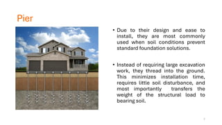
7.
Pier
• Due totheir design and ease to
install, they are most commonly
used when soil conditions prevent
standard foundation solutions.
• Instead of requiring large excavation
work, they thread into the ground.
This minimizes installation time,
requires little soil disturbance, and
most importantly transfers the
weight of the structural load to
bearing soil.
7
8.
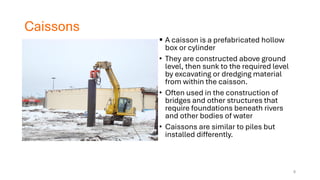
Caissons
▪ A caissonis a prefabricated hollow
box or cylinder
• They are constructed above ground
level, then sunk to the required level
by excavating or dredging material
from within the caisson.
• Often used in the construction of
bridges and other structures that
require foundations beneath rivers
and other bodies of water
• Caissons are similar to piles but
installed differently.
8
9.
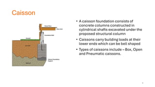
Caisson
• A caissonfoundation consists of
concrete columns constructed in
cylindrical shafts excavated under the
proposed structural column
• Caissons carry building loads at their
lower ends which can be bell shaped
• Types of caissons include – Box, Open
and Pneumatic caissons.
9
10.
Pile foundations -Classification
1. Type of material –
i. Timber ii. Steel iii. Concrete iv. Composite
2. Method of installation
i. Driven ii. Bored iii. Continuous Flight Auger
3. Degree of disturbance
i. Displacement (large – occurs for driven piles)
ii. Non-displacement (or small occurs for bored piles)
10
11.
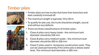
Timber piles
• Timberpiles are tree trunks that have their branches and
bark carefully trimmed off.
• The maximum length is typically 10 to 20 m.
• To qualify for pile use, the trunk should be straight, sound
and without any defects.
• There are three classifications of timber piles:
1. Class A piles carry heavy loads - the minimum butt
diameter should be 356 mm
2. Class B piles carry medium loads – the minimum butt
diameter should be 305 to 330 mm
3. Class C piles used in temporary construction work. They
can be used permanently if the entire pile is below water
level. The minimum butt diameter is 305 mm.
11
12.
Timber piles
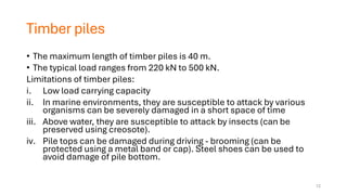
• Themaximum length of timber piles is 40 m.
• The typical load ranges from 220 kN to 500 kN.
Limitations of timber piles:
i. Low load carrying capacity
ii. In marine environments, they are susceptible to attack by various
organisms can be severely damaged in a short space of time
iii. Above water, they are susceptible to attack by insects (can be
preserved using creosote).
iv. Pile tops can be damaged during driving - brooming (can be
protected using a metal band or cap). Steel shoes can be used to
avoid damage of pile bottom.
12
13.
Timber piles
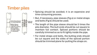
• Splicingshould be avoided; it is an expensive and
time-consuming process.
• But, if necessary, pipe sleeves (Fig a) or metal straps
and bolts (Fig b) should be used.
• The length of the pipe sleeve should be 5 times the
pile diameter. The butt ends should be cut square to
maintain full contact. Spliced portions should be
carefully trimmed so as to fit tightly inside the pipe.
• For metal straps and bolts, the butting ends should
be cut square and the sides of the spliced portion
should be trimmed plane for putting the straps on.
13
14.
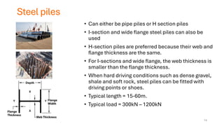
Steel piles
• Caneither be pipe piles or H section piles
• I-section and wide flange steel piles can also be
used
• H-section piles are preferred because their web and
flange thickness are the same.
• For I-sections and wide flange, the web thickness is
smaller than the flange thickness.
• When hard driving conditions such as dense gravel,
shale and soft rock, steel piles can be fitted with
driving points or shoes.
• Typical length = 15-60m.
• Typical load = 300kN – 1200kN
14
15.
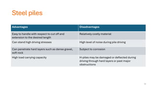
Steel piles
Advantages Disadvantages
Easyto handle with respect to cut off and
extension to the desired length
Relatively costly material
Can stand high driving stresses High level of noise during pile driving
Can penetrate hard layers such as dense gravel,
soft rock
Subject to corrosion
High load carrying capacity H-piles may be damaged or deflected during
driving through hard layers or past major
obstructions
15
16.
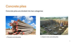
Concrete piles
• Concretepilesare divided into two basic types:
i. Precast piles
ii. Cast-in-situ piles
Concrete piles are divided into two categories
i. Precast concrete piles ii. Cast-in-situ concrete piles
16
17.
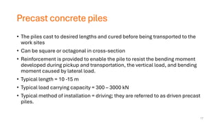
Precast concrete piles
•The piles cast to desired lengths and cured before being transported to the
work sites
• Can be square or octagonal in cross-section
• Reinforcement is provided to enable the pile to resist the bending moment
developed during pickup and transportation, the vertical load, and bending
moment caused by lateral load.
• Typical length = 10 -15 m
• Typical load carrying capacity = 300 – 3000 kN
• Typical method of installation = driving; they are referred to as driven precast
piles.
17
18.
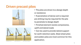
Driven precast piles
•The piles are driven to a design depth
or resistance
• If penetration of dense soil is required
pre-drilling may be required for the pile
to penetrate to design depth
• Finished element resists compressive,
uplift and lateral loads
• Can be used to provide lateral support
for earth retention walls. Steel sheet piles
and soldier piles are most common for this
application.
18
19.
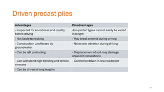
Driven precast piles
AdvantagesDisadvantages
- Inspected for soundness and quality
before driving
-Un-jointed types cannot easily be varied
in length
- Not liable to necking - May break or bend during driving
- Construction unaffected by
groundwater
- Noise and vibration during driving
- Can be left protruding - Displacement of soil may damage
adjacent installations
- Can withstand high bending and tensile
stresses
- Cannot be driven in low headroom
- Can be driven in long lengths
19
20.
Cast-in-situ piles
• Constructedby making a hole in the ground and then filling it with concrete.
• Various types are currently used in construction, and most have been
patented by their manufacturers.
i. Bored piles
ii. Continuous flight auger
iii. Franki pile
20
21.
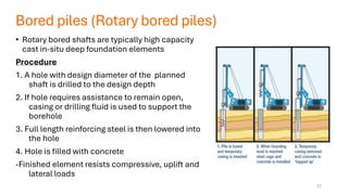
Bored piles (Rotarybored piles)
• Rotary bored shafts are typically high capacity
cast in-situ deep foundation elements
Procedure
1. A hole with design diameter of the planned
shaft is drilled to the design depth
2. If hole requires assistance to remain open,
casing or drilling fluid is used to support the
borehole
3. Full length reinforcing steel is then lowered into
the hole
4. Hole is filled with concrete
-Finished element resists compressive, uplift and
lateral loads
21
22.
Bored piles (Rotarybored)
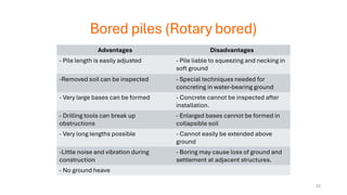
Advantages Disadvantages
- Pile length is easily adjusted - Pile liable to squeezing and necking in
soft ground
-Removed soil can be inspected - Special techniques needed for
concreting in water-bearing ground
- Very large bases can be formed - Concrete cannot be inspected after
installation.
- Drilling tools can break up
obstructions
- Enlarged bases cannot be formed in
collapsible soil
- Very long lengths possible - Cannot easily be extended above
ground
-Little noise and vibration during
construction
- Boring may cause loss of ground and
settlement at adjacent structures.
- No ground heave
22
23.
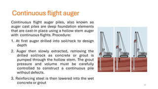
Continuous flight auger
Continuousflight auger piles, also known as
auger cast piles are deep foundation elements
that are cast-in place using a hollow stem auger
with continuous flights. Procedure:
1. At first auger drilled into soil/rock to design
depth
2. Auger then slowly extracted, removing the
drilled soil/rock as concrete or grout is
pumped through the hollow stem. The grout
pressure and volume must be carefully
controlled to construct a continuous pile
without defects.
3. Reinforcing steel is then lowered into the wet
concrete or grout 23
24.
Continuous flight augerpiles
Advantages Disadvantages
Minimal levels of vibration Longer installation period
Lower noise levels generated by pile rig Generally, more expensive
Much higher load capacities on larger diameter
piles
Requires casing below water table level
The risk of concrete drying out which can cause
problems with the installation of the steel cages.
24
25.
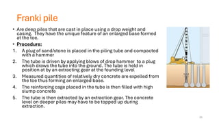
Franki pile
• Aredeep piles that are cast in place using a drop weight and
casing. They have the unique feature of an enlarged base formed
at the toe.
• Procedure:
1. A plug of sand/stone is placed in the piling tube and compacted
with a hammer
2. The tube is driven by applying blows of drop hammer to a plug
which draws the tube into the ground. The tube is held in
position at by an extracting gear at the founding level
3. Measured quantities of relatively dry concrete are expelled from
the toe thus forming an enlarged base.
4. The reinforcing cage placed in the tube is then filled with high
slump concrete
5. The tube is then extracted by an extraction gear. The concrete
level on deeper piles may have to be topped up during
extraction.
25
26.
Franki pile
Advantages Disadvantages
Enlargedbase increases load bearing capacity as end
bearing area is increased.
Depth of installation is limited
By enlarging the base the surrounding area is compacted
thereby increasing the ultimate end bearing stress.
Construction can be loud due to drop hammer.
The expansion of the base is a form of pre-loading of the
surrounding soil.
Relatively high vibration is produced during
construction.
The founding level is often at a higher elevation than that of
other piling systems resulting in a more economic design.
Not suitable for rocky soils
Resistance of large tension loads as the enlarged base
forms an ideal positive anchorage.
Good solution for structures in heaving clays where enlarged
base is in stable stratum thus effectively resisting uplift
movements from heave. For tension loads reinforcing cage
must be cast into the enlarged base
26
27.
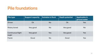
Pile foundations
Pile typeSupport capacity Suitable in Rock Depth potential Applicable in
ground water
Driven Ok No Ok Yes
Rotary bored Very good No Very good No
Continuous flight
auger
Very good Yes Very good Yes
Franki Good No Good Yes
27
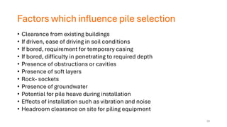
Factors which influencepile selection
• Clearance from existing buildings
• If driven, ease of driving in soil conditions
• If bored, requirement for temporary casing
• If bored, difficulty in penetrating to required depth
• Presence of obstructions or cavities
• Presence of soft layers
• Rock- sockets
• Presence of groundwater
• Potential for pile heave during installation
• Effects of installation such as vibration and noise
• Headroom clearance on site for piling equipment
29
30.
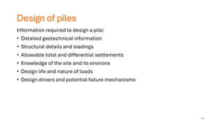
Design of piles
Informationrequired to design a pile:
• Detailed geotechnical information
• Structural details and loadings
• Allowable total and differential settlements
• Knowledge of the site and its environs
• Design life and nature of loads
• Design drivers and potential failure mechanisms
30
31.
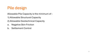
Pile design
Allowable PileCapacity is the minimum of :
1) Allowable Structural Capacity
2) Allowable Geotechnical Capacity
a. Negative Skin Friction
b. Settlement Control
31
32.
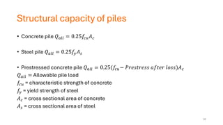
Structural capacity ofpiles
• Concrete pile 𝑄𝑎𝑙𝑙 = 0.25𝑓𝑐𝑢𝐴𝑐
• Steel pile 𝑄𝑎𝑙𝑙 = 0.25𝑓𝑦𝐴𝑠
• Prestressed concrete pile 𝑄𝑎𝑙𝑙 = 0.25(𝑓𝑐𝑢− 𝑃𝑟𝑒𝑠𝑡𝑟𝑒𝑠𝑠 𝑎𝑓𝑡𝑒𝑟 𝑙𝑜𝑠𝑠)𝐴𝑐
𝑄𝑎𝑙𝑙 = Allowable pile load
𝑓𝑐𝑢 = characteristic strength of concrete
𝑓𝑦 = yield strength of steel
𝐴𝑐 = cross sectional area of concrete
𝐴𝑠 = cross sectional area of steel
32
33.
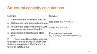
Structural capacity calculations
Example
1.Determine the allowable load for:
a. 300 mm dia. pile grade 40 concrete
b. 450 mm dia grade 40 concrete with
prestress after loss of 18 mPa
c. 360 x 420 mm High tensile steel
pile
2. Determine the suitable pile size
to support a load of 300 kN given that
the concrete grade is 30mPa and the
factor of safety is 1.5
Solution
Concrete
Steel
Pre-stressed concrete
𝑄𝑎𝑙𝑙 = 0.25𝑓𝑐𝑢𝐴𝑐
𝑄𝑎𝑙𝑙 = 0.3𝑓𝑦𝐴𝑠
𝑄𝑎𝑙𝑙 = 0.25(𝑓𝑐𝑢− 𝑃𝑟𝑒𝑠𝑡𝑟𝑒𝑠𝑠 𝑎𝑓𝑡𝑒𝑟 𝑙𝑜𝑠𝑠)𝐴𝑐
33
34.
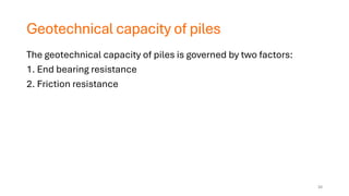
Geotechnical capacity ofpiles
The geotechnical capacity of piles is governed by two factors:
1. End bearing resistance
2. Friction resistance
34
35.
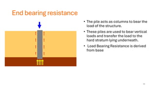
End bearing resistance
•The pile acts as columns to bear the
load of the structure.
• These piles are used to bear vertical
loads and transfer the load to the
hard stratum lying underneath.
• Load Bearing Resistance is derived
from base
35
36.
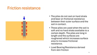
Friction resistance
• Thepiles do not rest on hard strata
and bear on frictional resistance
between their outer surface and the
soil in contact.
• These piles are used when the soil is
soft and no hard strata available to a
certain depth. The piles are long in
length and the surfaces are
roughened which increases surface
area to increase frictional
resistance.
• Load Bearing Resistance derived
from skin friction
36
37.
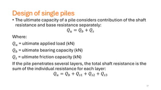
Design of singlepiles
• The ultimate capacity of a pile considers contribution of the shaft
resistance and base resistance separately:
𝑄𝑢 = 𝑄𝑏 + 𝑄𝑠
Where:
𝑄𝑢 = ultimate applied load (kN)
𝑄𝑏 = ultimate bearing capacity (kN)
𝑄𝑠 = ultimate friction capacity (kN)
If the pile penetrates several layers, the total shaft resistance is the
sum of the individual resistance for each layer:
𝑄𝑢 = 𝑄𝑏 + 𝑄𝑠1 + 𝑄𝑠2 + 𝑄𝑠3
37
38.
Design of singlepiles – Factors of safety
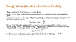
• Factors of safety: Working load of piles (Qall)
The working or safe load of a pile is a proportion of the ultimate load capacity of the
pile.
This ratio is defined as the factor of safety and is generally chosen by the designer with
a value between 2 and 3
𝑊𝑜𝑟𝑘𝑖𝑛𝑔 𝑙𝑜𝑎𝑑 =
𝑄𝑢
𝐹𝑆
A lower FS of 2 can be applied to Qs since movements required to mobilise shaft
capacity are small. Large movements are required to mobilise ultimate end bearing
capacity Qb and a larger factor of safety of 3 is adopted
𝑄𝑎𝑙𝑙 =
𝑄𝑠
2
+
𝑄𝑏
3
The British standard code adopts a global safety factor of 2.5 : 𝑄𝑎𝑙𝑙 =
𝑄𝑏+𝑄𝑠
2.5
38
39.
Design of singlepiles
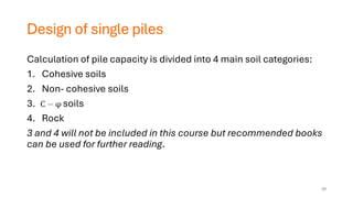
Calculation of pile capacity is divided into 4 main soil categories:
1. Cohesive soils
2. Non- cohesive soils
3. soils
4. Rock
3 and 4 will not be included in this course but recommended books
can be used for further reading.
39
40.
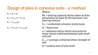
Design of pilesin cohesive soils - 𝛼 method
Where
Nc = bearing capacity factor taken as 9 for
penetration at least 5x the diameter into
bearing stratum
Cu,b = undrained cohesion at pile base
Ab = base area
𝛼 = adhesion factor which accounts for
shear stress mobilised between pile shaft
and soil
Cu, avg = average undrained shear strength of
pile
As = surface area of pile shaft
𝑄𝑢 = 𝑄𝑏 + 𝑄𝑠
𝑄𝑏 = 𝑁𝑐𝑐𝑢,𝑏𝐴𝑏 = 9 𝑐𝑢𝐴𝑏
𝑄𝑠 = 𝛼𝑐𝑢,𝑎𝑣𝑔𝑝𝐿
𝑄𝑢 = 9𝑐𝑢,𝑏𝐴𝑏 + 𝛼𝑐𝑢,𝑎𝑣𝑔𝑝𝐿
40
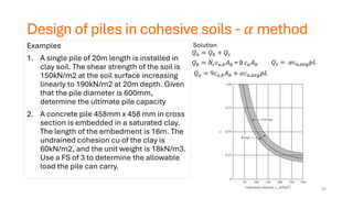
Design of pilesin cohesive soils - 𝛼 method
Examples
1. A single pile of 20m length is installed in
clay soil. The shear strength of the soil is
150kN/m2 at the soil surface increasing
linearly to 190kN/m2 at 20m depth. Given
that the pile diameter is 600mm,
determine the ultimate pile capacity
2. A concrete pile 458mm x 458 mm in cross
section is embedded in a saturated clay.
The length of the embedment is 16m. The
undrained cohesion cu of the clay is
60kN/m2, and the unit weight is 18kN/m3.
Use a FS of 3 to determine the allowable
load the pile can carry.
Solution
𝑄𝑢 = 𝑄𝑏 + 𝑄𝑠
𝑄𝑏 = 𝑁𝑐𝑐𝑢,𝑏𝐴𝑏 = 9 𝑐𝑢𝐴𝑏 𝑄𝑠 = 𝛼𝑐𝑢,𝑎𝑣𝑔𝑝𝐿
𝑄𝑢 = 9𝑐𝑢,𝑏𝐴𝑏 + 𝛼𝑐𝑢,𝑎𝑣𝑔𝑝𝐿
42
43.
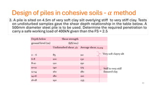
Design of pilesin cohesive soils - 𝛼 method
3. A pile is sited on 4.5m of very soft clay silt overlying stiff to very stiff clay. Tests
on undisturbed samples gave the shear depth relationship in the table below. A
500mm diameter steel pile is to be used. Determine the required penetration to
carry a safe working load of 400kN given than the FS = 2.5
43
44.
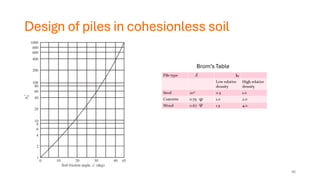
Design of pilesin cohesionless soils
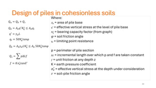
Where:
𝐴𝑏 = area of pile base
𝑞′
= effective vertical stress at the level of pile base
𝑁𝑞
∗
= bearing capacity factor (from graph)
𝜑 = soil friction angle
𝑞𝑙 = limiting point resistance
p = perimeter of pile section
∆𝐿 = incremental length over which p and f are taken constant
𝑓 = unit friction at any depth z
K = earth pressure coefficient
𝜎𝑣
′
= effective vertical stress at the depth under consideration
𝛿′
= soil-pile friction angle
𝑄𝑢 = 𝑄𝑏 + 𝑄𝑠
𝑄𝑏 = 𝐴𝑏𝑞′
𝑁𝑞
∗
≤ 𝐴𝑏𝑞𝑙
𝑞𝑙 = 50𝑁𝑞
∗
𝑡𝑎𝑛𝜑
𝑄𝑏 = 𝐴𝑏𝛾𝑑𝐿𝑁𝑞
∗
≤ 𝐴𝑏 50𝑁𝑞
∗
𝑡𝑎𝑛𝜑
𝑄𝑠 = 𝑝∆𝐿𝑓
𝑓 = 𝐾𝜎𝑣
′
𝑡𝑎𝑛𝛿′
𝑞′ = 𝛾𝑑𝐿
44
45.
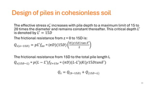
Design of pilesin cohesionless soil
The effective stress 𝜎𝑣
′ increases with pile depth to a maximum limit of 15 to
20 times the diameter and remains constant thereafter. This critical depth 𝐿′
is denoted by 𝐿′ = 15𝐷
The frictional resistance from z = 0 to 15D is:
𝑄𝑠(𝑜−15𝐷) = 𝑝𝐿′𝑓𝑎𝑣 = (𝜋𝐷)(15𝐷)
𝐾 𝛾15𝐷 tan 𝛿′
2
The frictional resistance from 15D to the total pile length L
𝑄𝑠(15𝐷−𝐿) = 𝑝(𝐿 − 𝐿′)𝑓𝑍=15𝑣 = (𝜋𝐷)(𝐿-𝐿′)(𝐾(𝛾15𝐷𝑡𝑎𝑛𝛿′)
𝑄𝑠 = 𝑄(0−15𝐷) + 𝑄(15𝐷−𝐿)
45
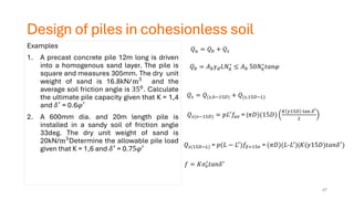
Design of pilesin cohesionless soil
Examples
1. A precast concrete pile 12m long is driven
into a homogenous sand layer. The pile is
square and measures 305mm. The dry unit
weight of sand is 16.8kN/m3
and the
average soil friction angle is 350. Calculate
the ultimate pile capacity given that K = 1,4
and 𝛿′ = 0.6𝜑′
2. A 600mm dia. and 20m length pile is
installed in a sandy soil of friction angle
33deg. The dry unit weight of sand is
20kN/m3Determine the allowable pile load
given that K = 1,6 and 𝛿′ = 0.75𝜑′
𝑄𝑏 = 𝐴𝑏𝛾𝑑𝐿𝑁𝑞
∗
≤ 𝐴𝑏 50𝑁𝑞
∗
𝑡𝑎𝑛𝜑
𝑄𝑢 = 𝑄𝑏 + 𝑄𝑠
𝑄𝑠 = 𝑄(𝑠,0−15𝐷) + 𝑄(𝑠,15𝐷−𝐿)
𝑄𝑠(𝑜−15𝐷) = 𝑝𝐿′
𝑓𝑎𝑣 = (𝜋𝐷)(15𝐷)
𝐾 𝛾15𝐷 tan 𝛿′
2
𝑄𝑠(15𝐷−𝐿) = 𝑝(𝐿 − 𝐿′
)𝑓𝑍=15𝑣 = (𝜋𝐷)(𝐿-𝐿′
)(𝐾(𝛾15𝐷)𝑡𝑎𝑛𝛿′
)
47
𝑓 = 𝐾𝜎𝑣
′
𝑡𝑎𝑛𝛿′
48.
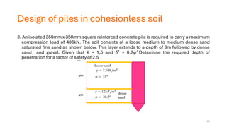
Design of pilesin cohesionless soil
3. An isolated 350mm x 350mm square reinforced concrete pile is required to carry a maximum
compression load of 400kN. The soil consists of a loose medium to medium dense sand
saturated fine sand as shown below. This layer extends to a depth of 9m followed by dense
sand and gravel. Given that K = 1,5 and 𝛿′ = 0.7𝜑′ Determine the required depth of
penetration for a factor of safety of 2.5
48
49.
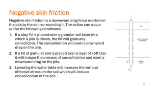
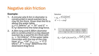
Negative skin friction
Negativeskin friction is a downward drag force exerted on
the pile by the soil surrounding it. The action can occur
under the following conditions:
1. If a clay fill is placed over a granular soil layer into
which a pile is driven, the fill will gradually
consolidate. The consolidation will exert a downward
drag on the pile.
2. If a fill of granular soil is placed over a layer of soft clay
it will induce the process of consolidation and exert a
downward drag on the pile.
3. Lowering the water table will increase the vertical
effective stress on the soil which will induce
consolidation of the soil.
49
50.
Negative skin friction-preventive measures
• Avoid fill material
• Preload before constructing piles
• Sleeve the pile shaft
• Allow for larger settlements
50
51.
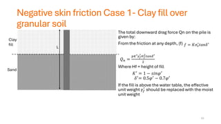
Negative skin frictionCase 1- Clay fill over
granular soil
The total downward drag force Qn on the pile is
given by:
From the friction at any depth, (f)
𝑄𝑛 =
𝑝𝐾′𝛾𝑓
′
𝐻𝑓
2
𝑡𝑎𝑛𝛿′
2
Where Hf = height of fill
𝐾′ = 1 − 𝑠𝑖𝑛𝜑′
𝛿′= 0.5𝜑′ − 0.7𝜑′
If the fill is above the water table, the effective
unit weight 𝛾𝑓
′
should be replaced with the moist
unit weight
51
Clay
fill
Sand
L
𝑓 = 𝐾𝜎𝑣
′
𝑡𝑎𝑛𝛿′
52.
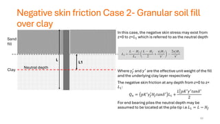
Negative skin frictionCase 2- Granular soil fill
over clay
In this case, the negative skin stress may exist from
z=0 to z=𝐿1 which is referred to as the neutral depth
Where 𝛾𝑓
′
and 𝛾′
are the effective unit weight of the fill
and the underlying clay layer respectively
The negative skin friction at any depth from z=0 to z=
𝐿1:
𝑄𝑛 = 𝑝𝐾′
𝛾𝑓
′
𝐻𝑓𝑡𝑎𝑛𝛿′
𝐿1 +
𝐿1
2
𝑝𝐾′
𝛾′
𝑡𝑎𝑛𝛿′
2
For end bearing piles the neutral depth may be
assumed to be located at the pile tip i.e 𝐿1 = 𝐿 − 𝐻𝑓
52
Sand
fill
Clay
L
L1
Neutral depth
53.
Negative skin friction
Example:
1.A circular pile 0.5m in diameter is
constructed in sand overlain by a
clay fill 3m thick. Given that the fill is
above the water table,
𝛾𝑓=17.2kN/m3, 𝜑′ = 36𝑜 𝑎𝑛𝑑 𝛿′ =
0.7𝜑′determine the total drag force.
2. A 20m long and 0.305m diameter
pile is constructed in a clay deposit
overlain by a sand fill 2m thick with
𝛾𝑓 = 16.5 kN/m3. If the water table
coincides with the top of the clay
layer, 𝜑𝑐𝑙𝑎𝑦
′
=34𝑜, 𝛾𝑠𝑎𝑡,𝑐𝑙𝑎𝑦 = 17.2
kN/m3
, 𝛿′
= 0.6𝜑′
determine the
downward drag force
53
Solution
1. 𝑄𝑛 =
𝑝𝐾′𝛾𝑓
′
𝐻𝑓
2
𝑡𝑎𝑛𝛿′
2
𝐾′ = 1 − 𝑠𝑖𝑛𝜑′
2.
𝑄𝑛 = 𝑝𝐾′
𝛾𝑓
′
𝐻𝑓𝑡𝑎𝑛𝛿′
𝐿1 +
𝐿1
2
𝑝𝐾′𝛾′𝑡𝑎𝑛𝛿′
2
54.
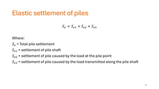
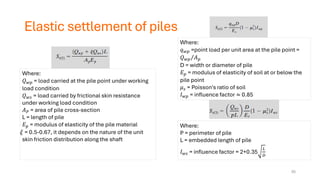
Elastic settlement ofpiles
𝑆𝑒 = 𝑆𝑒1 + 𝑆𝑒2 + 𝑆𝑒3
Where:
𝑆𝑒 = Total pile settlement
𝑆𝑒1 = settlement of pile shaft
𝑆𝑒2 = settlement of pile caused by the load at the pile point
𝑆𝑒3 = settlement of pile caused by the load transmitted along the pile shaft
54
55.
Elastic settlement ofpiles
Where:
𝑄𝑤𝑝 = load carried at the pile point under working
load condition
𝑄𝑤𝑠 = load carried by frictional skin resistance
under working load condition
𝐴𝑃 = area of pile cross-section
L = length of pile
𝐸𝑝 = modulus of elasticity of the pile material
= 0.5-0.67, it depends on the nature of the unit
skin friction distribution along the shaft
Where:
𝑞𝑤𝑝 =point load per unit area at the pile point =
Τ
𝑄𝑤𝑝 𝐴𝑝
D = width or diameter of pile
𝐸𝑝 = modulus of elasticity of soil at or below the
pile point
𝜇𝑠 = Poisson's ratio of soil
𝐼𝑤𝑝 = influence factor ≈ 0.85
Where:
P = perimeter of pile
L = embedded length of pile
𝐼𝑤𝑠 = influence factor = 2+0.35
𝐿
𝐷
55
56.
Elastic settlement ofpiles
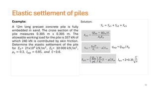
Example:
A 12m long precast concrete pile is fully
embedded in sand. The cross section of the
pile measures 0.305 m x 0.305 m. The
allowable working load for the pile is 337 kN of
which 240 kN is contributed by skin friction.
Determine the elastic settlement of the pile
for 𝐸𝑃= 21x106
𝑘𝑁/𝑚2
, 𝐸𝑆= 30 000 𝑘𝑁/𝑚2
,
𝜇𝑠 = 0.3, 𝐼𝑤𝑝 = 0.85, 𝑎𝑛𝑑 = 0.6.
Solution:
𝑆𝑒 = 𝑆𝑒1 + 𝑆𝑒2 + 𝑆𝑒3
𝑞𝑤𝑝 = Τ
𝑄𝑤𝑝 𝐴𝑝
𝐼𝑤𝑠 = 2+0.35
𝐿
𝐷
56
57.
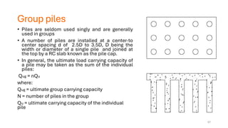
Group piles
• Pilesare seldom used singly and are generally
used in groups
• A number of piles are installed at a center-to
center spacing d of 2.5D to 3.5D, D being the
width or diameter of a single pile and joined at
the top by a RC slab known as the pile cap.
• In general, the ultimate load carrying capacity of
a pile may be taken as the sum of the individual
piles:
Qug = nQu
where:
Qug = ultimate group carrying capacity
N = number of piles in the group
Qu = ultimate carrying capacity of the individual
pile
57
58.
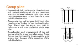
Group piles
• Inpractice it is found that the disturbance of
soil during installation of pile and overlap of
stresses between adjacent pile may cause
the group capacity to be less than the sum of
individual capacities.
• Conversely the soil between individual piles
may become “locked in” due to densification
from driving and the group may tend to
behave as a unit or an equivalent single large
pile.
• Densification and improvement of the soil
surrounding the group may also occur. These
factors may increase the group capacity to be
greater than the sum of the capacities of the
individual piles.
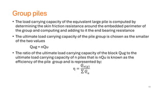
58
59.
Group piles
• Theload carrying capacity of the equivalent large pile is computed by
determining the skin friction resistance around the embedded perimeter of
the group and computing and adding to it the end bearing resistance
• The ultimate load carrying capacity of the pile group is chosen as the smaller
of the two values
Qug = nQu
• The ratio of the ultimate load carrying capacity of the block Qug to the
ultimate load carrying capacity of n piles that is nQu is known as the
efficiency of the pile group and is represented by:
η =
𝑄𝑢(𝑔)
σ 𝑄𝑢
59
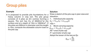
60.
Group piles
Example
It isproposed to provide pile foundations for a
heavy column in clay soil. The pile group
consists of 4 piles as 2m centres forming a
square. The soil has Cu of 60kN/m2
at the
surface and at a depth of 10m is 100kN/m2. If
the piles are 500mm in diameter and the length
is 10m, compute the allowable column load on
the pile cap
Solution
Draw a sketch of the pile cap in plan view and
elevation.
1. Individual pile capacity
nQu =
2. Block carrying capacity
Ab = area of pile cap
P = perimeter of pile cap
Adopt the lesser of the two as Qu
𝑄𝑎𝑙𝑙 =
𝑄𝑢
2.5
𝑄𝑢 = 9𝑐𝑢,𝑏𝐴𝑏 + 𝛼𝑐𝑢,𝑎𝑣𝑔𝑝𝐿
𝑄𝑢(𝑔) = 9𝑐𝑢,𝑏𝐴𝑏 + 𝛼𝑐𝑢,𝑎𝑣𝑔𝑝𝐿
60
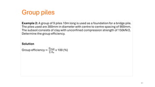
61.
Group piles
Example 2:A group of 9 piles 10m long is used as a foundation for a bridge pile.
The piles used are 300mm in diameter with centre to centre spacing of 900mm.
The subsoil consists of clay with unconfined compression strength of 150kN/2.
Determine the group efficiency.
Solution
Group efficiency =
𝑄𝑢(𝑔)
σ 𝑄𝑢
x 100 (%)
61
62.
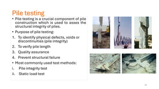
Pile testing
• Piletesting is a crucial component of pile
construction which is used to asses the
structural integrity of piles.
• Purpose of pile testing:
1. To identify physical defects, voids or
discontinuities (pile integrity)
2. To verify pile length
3. Quality assurance
4. Prevent structural failure
• Most commonly used test methods:
i. Pile integrity test
ii. Static load test
62
63.
Pile integrity test– low strain test
i. Low strain pile integrity test is a common non-destructive test (NDT) procedure for
quality control and quality assurance (QC/QA) in deep foundation construction
ii. Low Strain Pile Integrity Test belongs to a group of shaft head impact tests, where
the response of an impact made on the head of pile head is recorded by a motion
transducer (i.e. accelerometer), and used for analysis. Alternatively, engineers
can use other tests such as cross-hole or down-hole tests for the purpose of
integrity test.
• Pile Integrity Test Principle
The general principle behind the pile integrity test is relatively simple. By Assuming
that the stress wave travels at the speed of C inside the pile shaft, the pile depth can
be determined by measuring the time lapse, T, between striking pile head and
receiving reflections on pile head.
63
64.
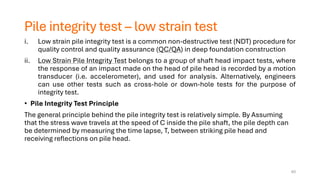
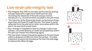
Low strain pileintegrity test
• Pile Integrity Test (PIT) is normally performed by striking
the pile head with a light hand-held hammer and
recording the response of the pile using a motion
transducer (i.e. accelerometer) coupled to the pile head.
• The hammer strike (blows) generate compressive stress
wave that will travel through the pile. This wave is partly
reflected from the pile toe or other anomalies within the
pile in its way back to pile head.
• Any change in impedance (due to change in pile cross
section, concrete density, or shaft-soil properties) within
the pile can impact the reflecting signal.
• The low strain impact should be applied to the pile head
within a distance of 300 mm from the sensor. It is also
important to place the transducer far from the pile edge
to reduce the effect of edge.
64
65.
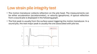
Low strain pileintegrity test
• The motion transducer collects reflection on the pile head. The measurements can
be either acceleration (accelerometer), or velocity (geophone). A typical reflection
from a sound pile is displayed in the following graph.
• The first peak is usually from the surface wave triggering the motion transducer. In a
sound pile, the next major peak is usually the one associated with pile toe.
65
66.
Static load test
•The static pile load test gives the most accurate indication of the capacity of the in-
place pile
• It can determine the ultimate failure load of a foundation pile and determine its
capacity to support the load without excessive or continuous displacement.
• The purpose of such tests is to verify that the load capacity in the constructed pile
is greater than the nominal resistance (Compression, Tension, Lateral) used in the
design.
• The method simulates the loading regime of the completed foundation.
Procedure:
A hydraulic jack is used to push the pile under test into the ground (for a conventional
compression test), using either the dead weight of kentledge (typically blocks of
precast concrete or iron, or a series of tension piles/anchors to provide the reaction
66
67.
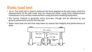
Static load test
•An in- line load cell is used to measure the force applied at the pile head, while the
displacement of the pile head may be measured either using local displacement
transducers or by remote measurement using precision levelling equipment.
• The former method is generally more accurate, though will be affected by any
ground settlements around the test pile
• Static load tests are the final step taken to assess the integrity and performance of
piles
67