
Recommended
More Related Content
Similar to dc motor.pptx
Similar to dc motor.pptx (20)
Recently uploaded
Recently uploaded (20)
dc motor.pptx
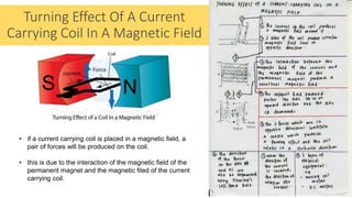
- 1. Turning Effect Of A Current Carrying Coil In A Magnetic Field • if a current carrying coil is placed in a magnetic field, a pair of forces will be produced on the coil. • this is due to the interaction of the magnetic field of the permanent magnet and the magnetic filed of the current carrying coil.
- 2. Catapult field of turning effect • the direction of the force can be determined by fleming's left hand rule. • since the current in both sides of the coil flow in opposite direction, the forces produced are also in opposite direction. • the 2 forces in opposite direction is called a couple which produces a turning effect to make the coil rotate. • examples of electric equipment whose operation is based on this turning effect are • the direct current motor • the moving coil meter. https://youtu.be/ORGlwSRRxkg
- 3. A couple is two equal forces which act in opposite directs on an object but not through the same point so they produce a turning effect. Turning effect of a couple N s F F Distance, s The moment (or torque) of a couple is calculated by multiplying the size of one of the force (F) by the perpendicular distance between the two forces (s). Moment of Couple = F x s the higher the moment of a couple, the higher the turning effect (the conductor moves faster)
- 4. Calculating turning effect of a couple N s F F S = 5cm N s F F N s F F S = 3cm S = 0cm 𝜃 =90° 𝜃 𝜃 = 0° When the 𝜃 between Force and distance is 90°, couple will experience the highest moment.it gives maximum speed of rotation to the coil. The moment is calculated: Moment = F x 5 = 5F As the coil rotates, the angle will decrease, the perpendicular distance also decrease causing the rotation to slow down The moment is calculated: Moment = F x 3 = 3F When the 𝜃 between Force and distance is 0°, couple will experience the 0 moment. Which means it gives minimum rotation to the coil. The moment is calculated: Moment = F x 0 = 0F
- 5. • an electric motor converts electrical energy to kinetic energy. • it consist a rectangular coil of wire placed between 2 permanent magnets. • the coil are soldered to a copper split ring known as commutator. • 2 carbon brushes are held against the commutator. • the function of the brush is to conduct electricity from the external circuit to the coil and allow the commutator to rotate continuously. • the function of the commutator is to change the direction of the current in the coil and hence change the direction of the couple (the 2 forces in opposite direction) in every half revolution. this is to make sure that the coil can rotate continuously. Direct current motor (DC motor)
- 6. Working principle of DC motor https://youtu.be/JmGl3xFk3SM STAGE 1 (ROTATION 0° - 90°) • Coil is parallel to the magnetic field. • Current flow into coil from S2 -> DC -> BA and flow out through S1 • Coil experience maximum speed of rotation STAGE 2 (ROTATION 90° - 180°) • Coil is perpendicular to the magnetic field. • Commutator is not touching the brush. • Coil moves because of inertia STAGE 3 (ROTATION 180° - 270°) • Coil is parallel to the magnetic field. • Current flow into coil from S1 -> AB -> CD and flow out through S2 • Coil experience maximum speed of rotation STAGE 4 (ROTATION 270° - 360°) • Coil is perpendicular to the magnetic field. • Commutator is not touching the brush. • Coil moves because of inertia
- 9. Sine graph of a dc motor 0° 90° 180° 270° 360°/0° Stage 1 Stage 2 Stage 3 Stage 4 Angle of rotation current Position of coil in dc motor
- 10. Application Of The Force On A Current Carrying Conductor In A Magnetic Field YOUR TASK: You are required to make an infographic poster on the working principle of device that is applying the force of current carrying conductor in a magnetic field. You may choose to explain on the working principle of: - Loudspeaker - Moving-coil meter - Or any device that relevant Your work must be submitted through Google classroom by 16/4/2020