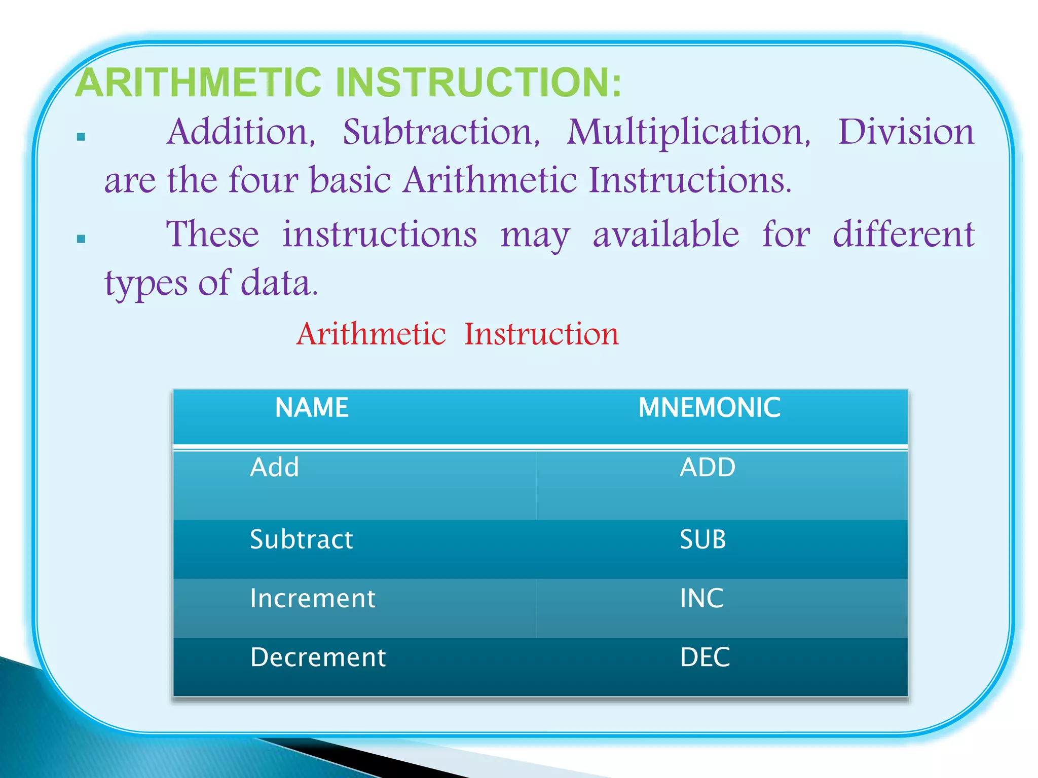
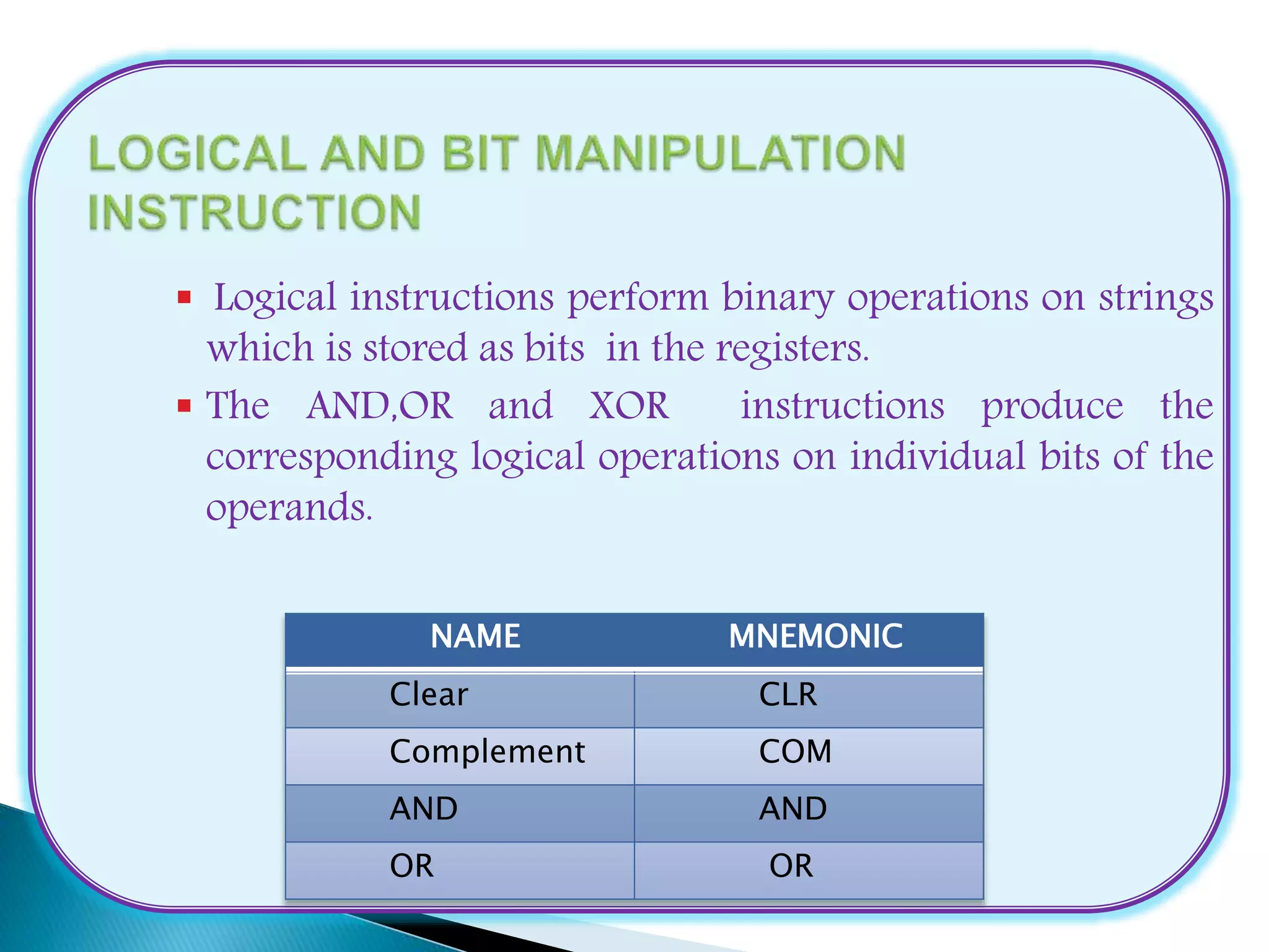
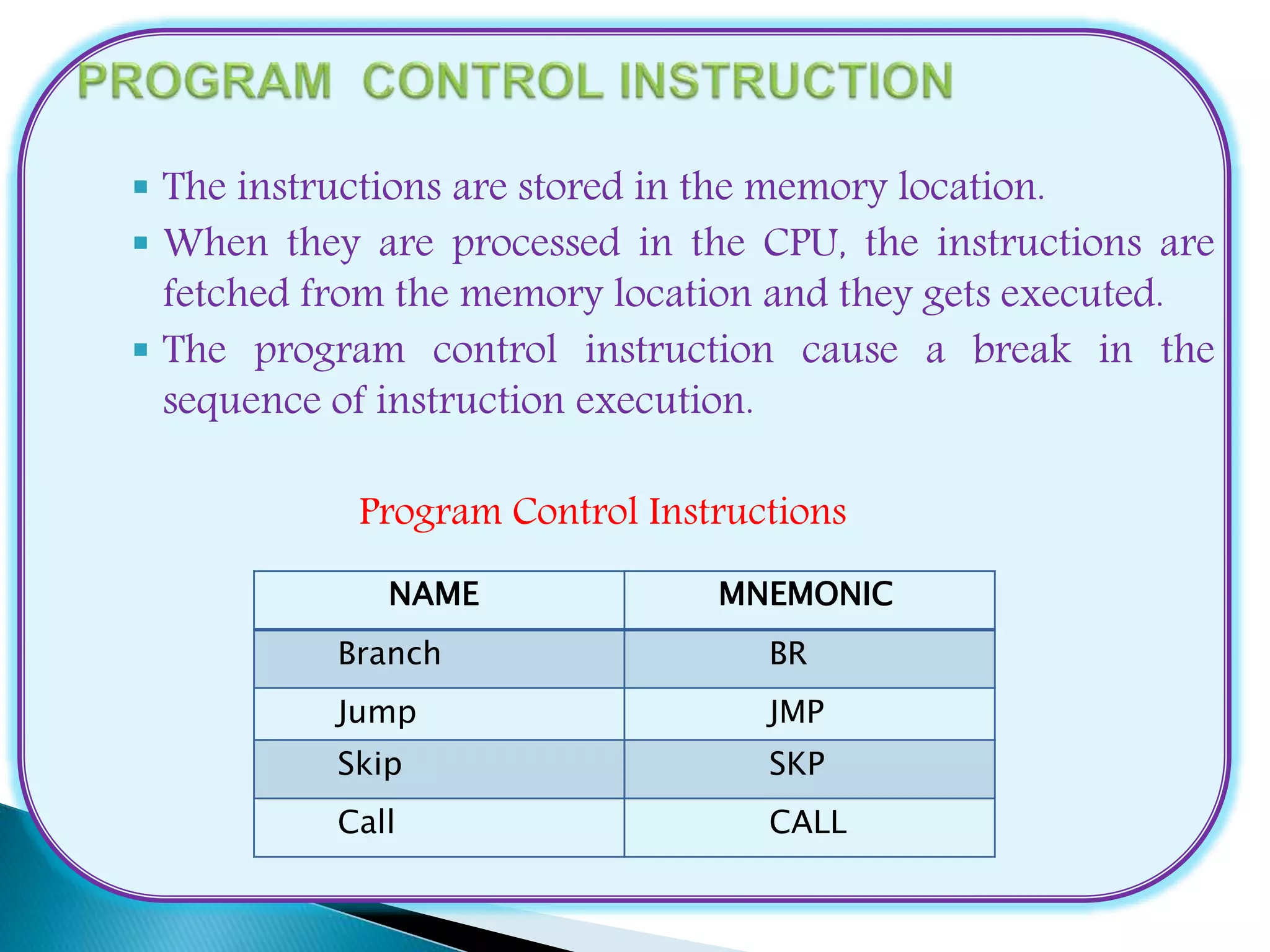
2. Computers provide an extensive set of
instructions to give the user to carry out various
computational tasks.
They can be classified into three types
1.Data Transfer Instructions
2.Data Manipulation Instructions
3.Program Control Instructions
DATA TRANSFER INSTRUCTIONS:
Data Transfer Instructions transfers data from one
location to another without changing the binary
information content.
3. Data Manipulation Instructions performs
operations on data and provides computational capabilities
for the computer.
Three basic types are:
1.Arithmetic Instruction
2.Logical and bit Manipulation Instruction
3.Shift Instruction
The each instructions when executed in the computer, they
must enter through the fetch phase to read its binary code
value from memory.
4. ARITHMETIC INSTRUCTION:
Addition, Subtraction, Multiplication, Division
are the four basic Arithmetic Instructions.
These instructions may available for different
types of data.
Arithmetic Instruction
NAME MNEMONIC
Add ADD
Subtract SUB
Increment INC
Decrement DEC
5. Logical instructions perform binary operations on strings
which is stored as bits in the registers.
The AND,OR and XOR instructions produce the
corresponding logical operations on individual bits of the
operands.
NAME MNEMONIC
Clear CLR
Complement COM
AND AND
OR OR
6. Shift instructions are used to shift the bits either in left or
right side in the operation.
The logical shift inserts 0 at the end bit position.
The end position is the leftmost bit for shift right and
rightmost bit position for the shift left.
NAME MNEMONIC
Logical Shift Right SHR
Logical Shift Left SHL
Rotate right ROR
Rotate Left ROL
7. The instructions are stored in the memory location.
When they are processed in the CPU, the instructions are
fetched from the memory location and they gets executed.
The program control instruction cause a break in the
sequence of instruction execution.
Program Control Instructions
NAME MNEMONIC
Branch BR
Jump JMP
Skip SKP
Call CALL
8. Microinstructions are stored in control memory in groups,
with each group specifying a “routine”.
A machine instruction may have bits that specify various
addressing modes, such as indirect and index registers.
There are 4 types of address sequencing.
1. Incrementing of the Control Address register
2. Unconditional branch or conditional branch,
depending on status bit conditions
3. A mapping process from the bits of the instruction to
an address for control memory.
4. A facility for subroutine call and return.
9. A conditional branch microinstruction can be
implemented by loading the branch address from
control memory into the control address register.
This can be accomplished by fixing the value of one
status bit and the input of the multiplexer.
The status lines from control memory causes the
branch address register.
The status bits, together with the field in the
microinstruction that specifies a branch address,
control the conditional branch decisions generated in
the branch logic.
10. A special type of branch exists when a
microinstruction specifies a branch to the first word
in control memory where a micro program routine
for an instruction is located.
Mapping from instruction code to microinstruction address
Computer Instruction
Mapping Bits 0 1 1 1 0 0
Microinstruction Address
0 1 1 1 address
0 1 0 1 1 0 0
11. Subroutines are programs that are used by other
routines to accomplish a particular task.
A subroutine can be called from any point within the
main body of the micro program.
Many micro programs contain identical sections of
code.
Micro instructions can be saved by employing
subroutines that use common sections of micro code.
Micro programs that use subroutines must have a
provision for storing the return address during a
subroutine call and restoring the address during a
subroutine return.
12. Once the configuration of a computer and its
micro programmed control unit is established, the
designers task is to generate the microcode for the
control memory.
COMPUTER CONFIGURATION:
It consists of two memory units.
One is main memory, which is used for storing
instruction and data and another one is control
memory is used for storing the micro program.
Four registers are associated with the processor
unit and two with control unit.
13. The micro instruction format for 20 bits is divided
into four functional parts.
The micro operations are subdivided into three fields
of the three bits.
Instruction Format
Micro instruction Code Format
1 OP CODE Address
F1 ADF2 F3 CD BR