
Download to read offline


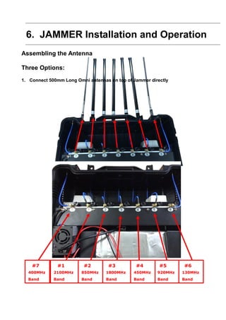
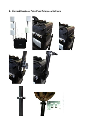
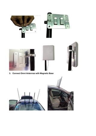
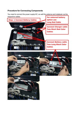
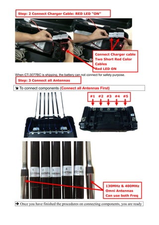
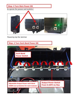
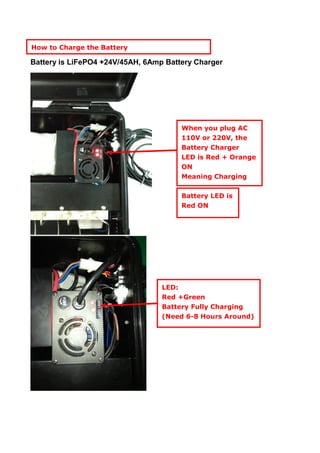
The CT-3077BC jammer operating guide provides detailed information on the use, installation, and maintenance of the jammer unit, which is designed to block various cellular frequencies effectively. It is particularly aimed at military and police users, ensuring operational safety and efficiency while adhering to local laws and regulations. The document outlines specifications, components, and a step-by-step procedure for setup and operation.


