Principles of tomography, CT Generations, X- Ray sources- collimation- X- Ray detectors – Viewing systems – spiral CT scanning – Ultra fast CT scanners. Image reconstruction techniques – back projection and iterative method
UNIT II COMPUTEDTOMOGRAPHY
Principles of tomography, CT Generations, X- Ray sources-
collimation- X- Ray detectors – Viewing systems – spiral
CT scanning – Ultra fast CT scanners. Image
reconstruction techniques – back projection and iterative
method
2.
Limitations of X-RAYS
•Firstly, the super-imposition of the three-dimensional information
onto a single plane makes diagnosis confusing and often difficult.
• Secondly, the photographic film usually used for making radiographs
has a limited dynamic range and, therefore, only objects that have
large variations in X-ray absorption relative to their surroundings will
cause sufficient contrast differences on the film to be distinguished by
the eye.
3.
computed tomography
• Incomputed tomography the picture is made by viewing the patient
via X-ray imaging from numerous angles, by mathematically
reconstructing the detailed structures and displaying the
reconstructed image on a video monitor.
• Computed tomography differs from conventional X-ray techniques in
that the pictures displayed are not photographs but are reconstructed
from a large number of absorption profiles taken at regular angular
intervals around a slice
4.
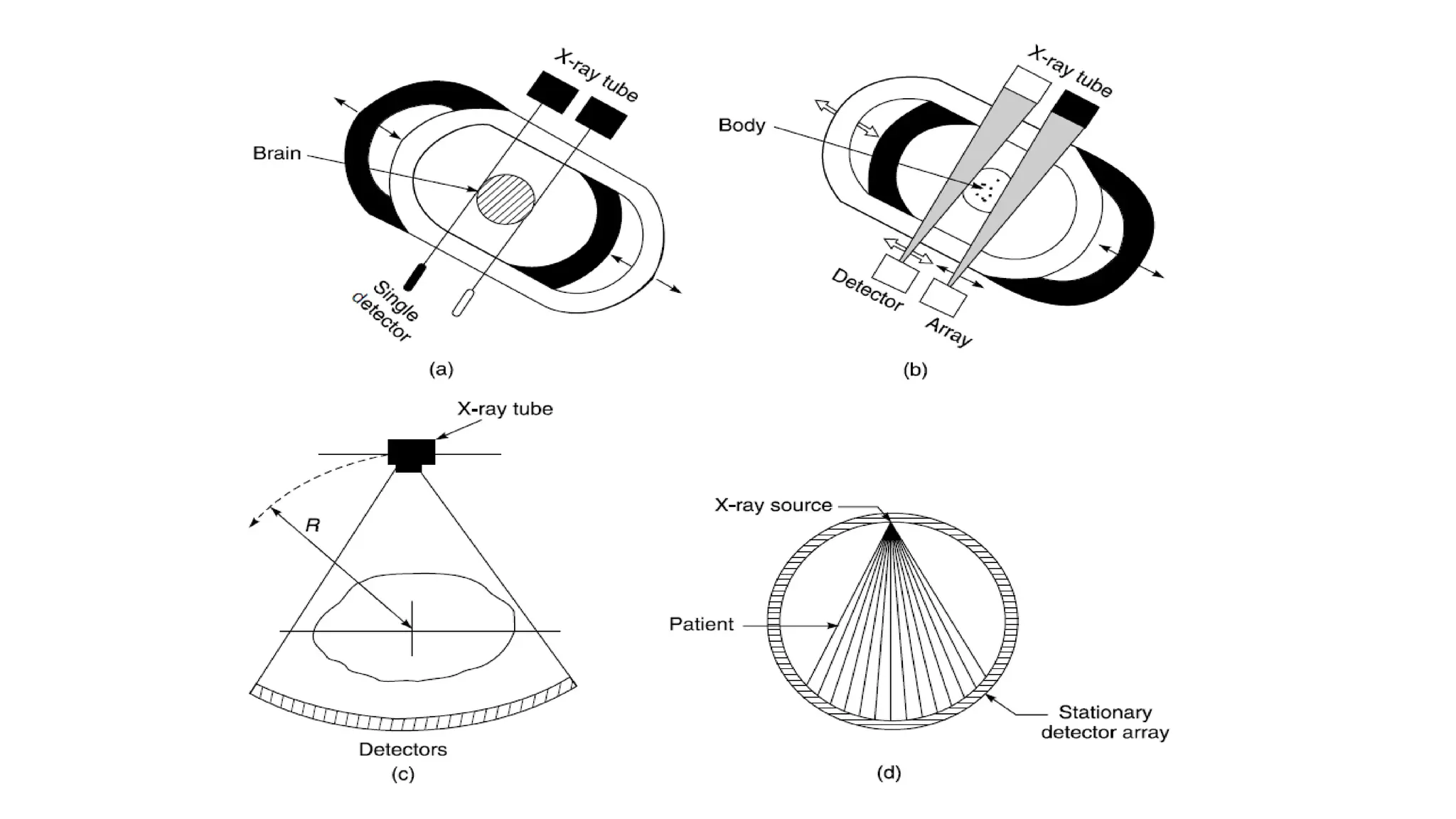
PRINCIPLES OF TOMOGRAPHY
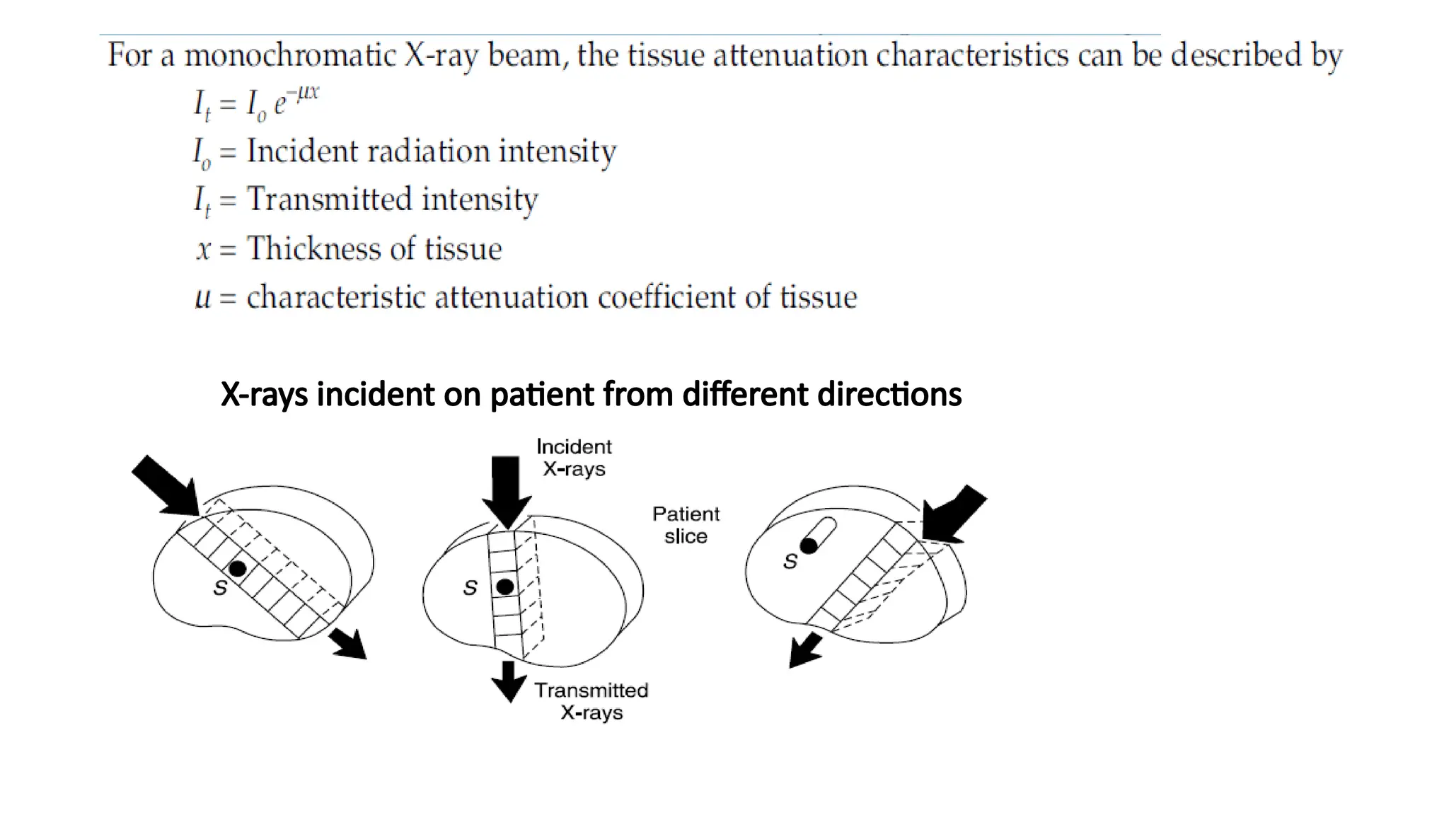
•In computed tomography, X-rays from a finely collimated source are
made to pass through the patient from different directions.
• The directions in which the path length is longer, more X-rays are
attenuated ,.
• computed tomography determines the attenuation characteristics for
each small volume of tissue in the patient slice, which constitute the
transmitted radiation intensity recorded from various irradiation
directions.
• These calculated tissue attenuation characteristics compose the CT
image.
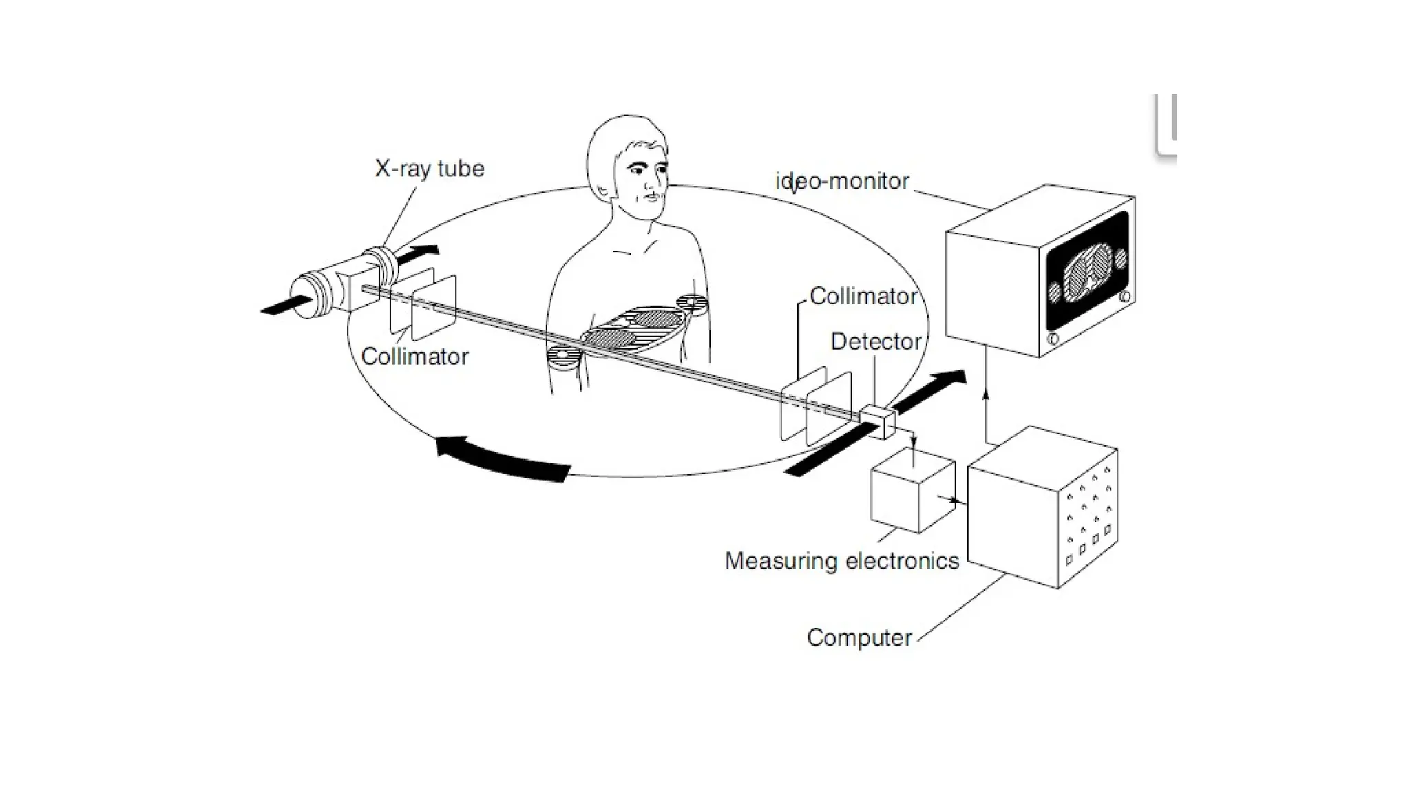
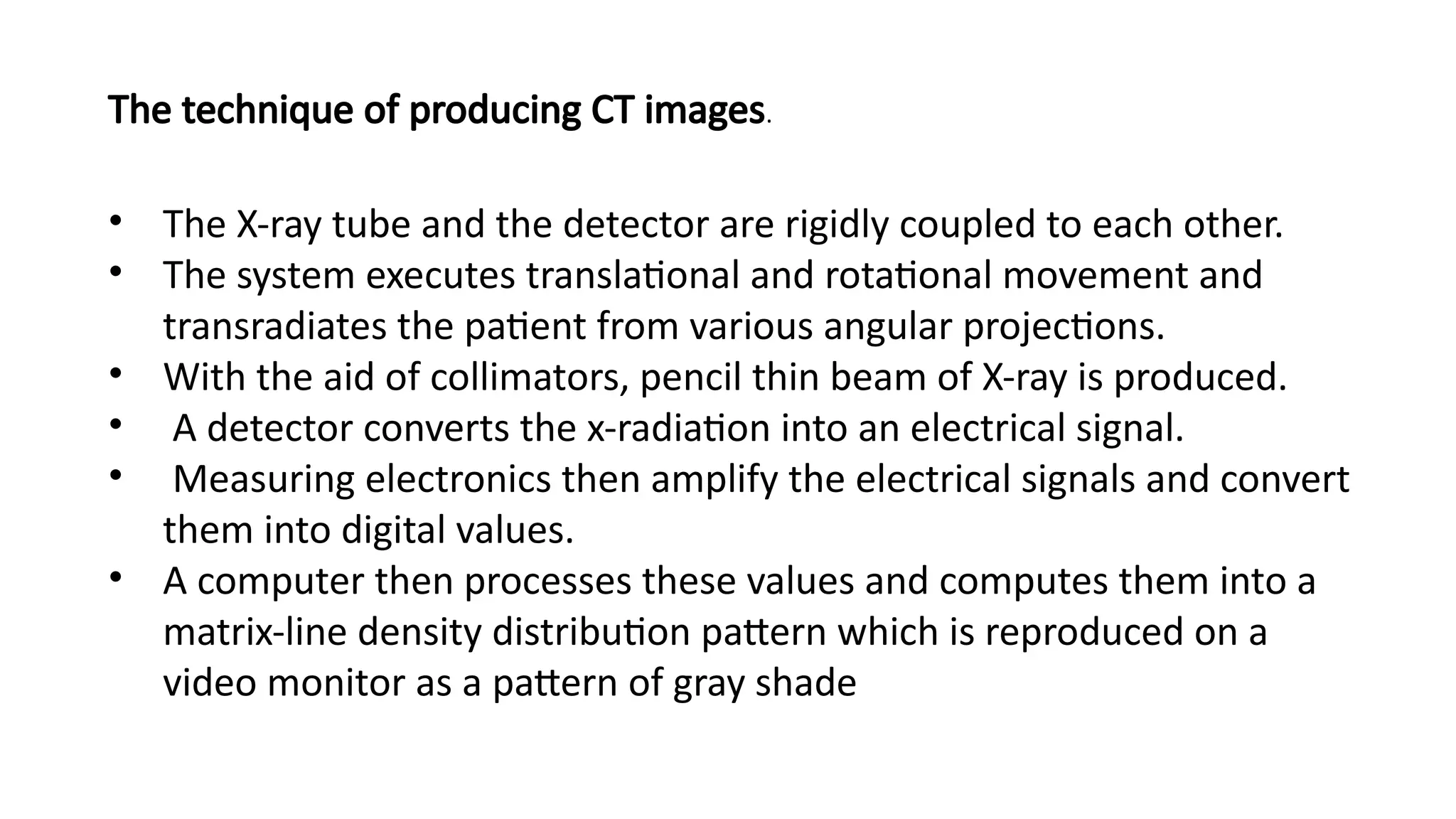
• The X-raytube and the detector are rigidly coupled to each other.
• The system executes translational and rotational movement and
transradiates the patient from various angular projections.
• With the aid of collimators, pencil thin beam of X-ray is produced.
• A detector converts the x-radiation into an electrical signal.
• Measuring electronics then amplify the electrical signals and convert
them into digital values.
• A computer then processes these values and computes them into a
matrix-line density distribution pattern which is reproduced on a
video monitor as a pattern of gray shade
The technique of producing CT images.
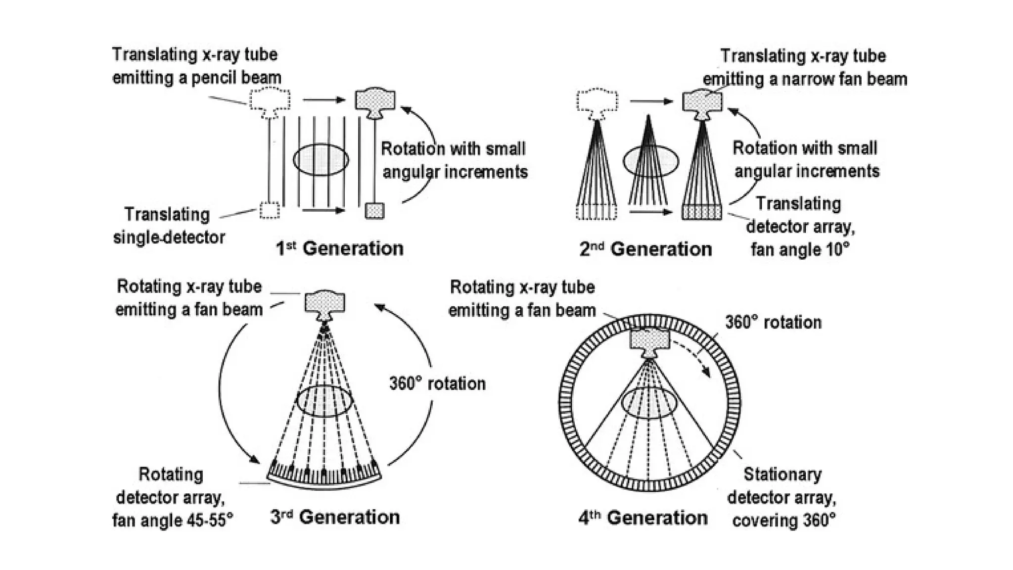
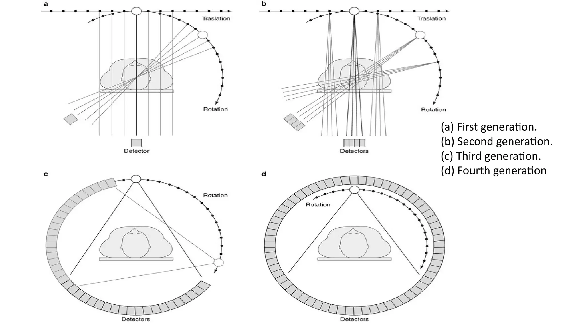
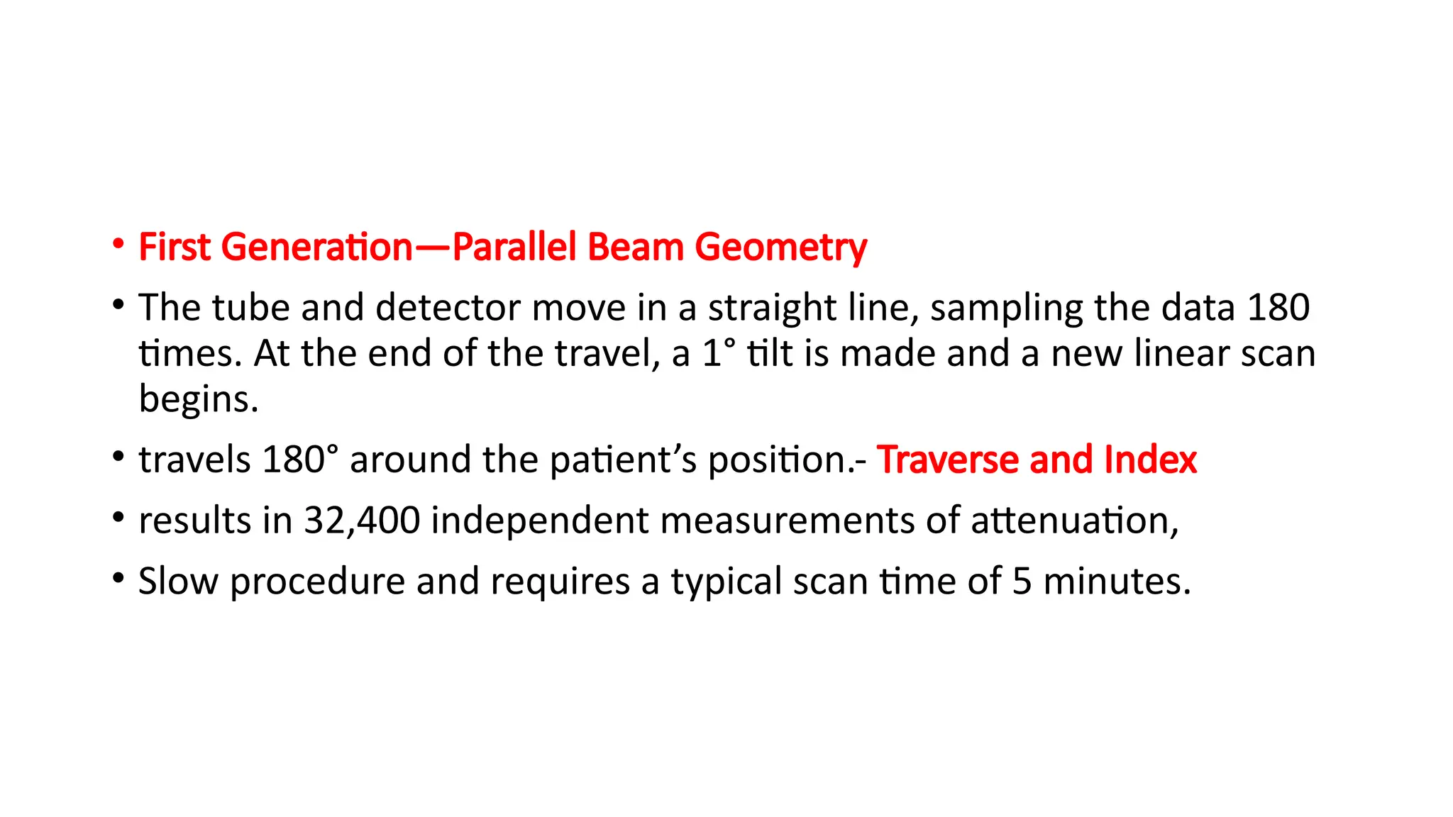
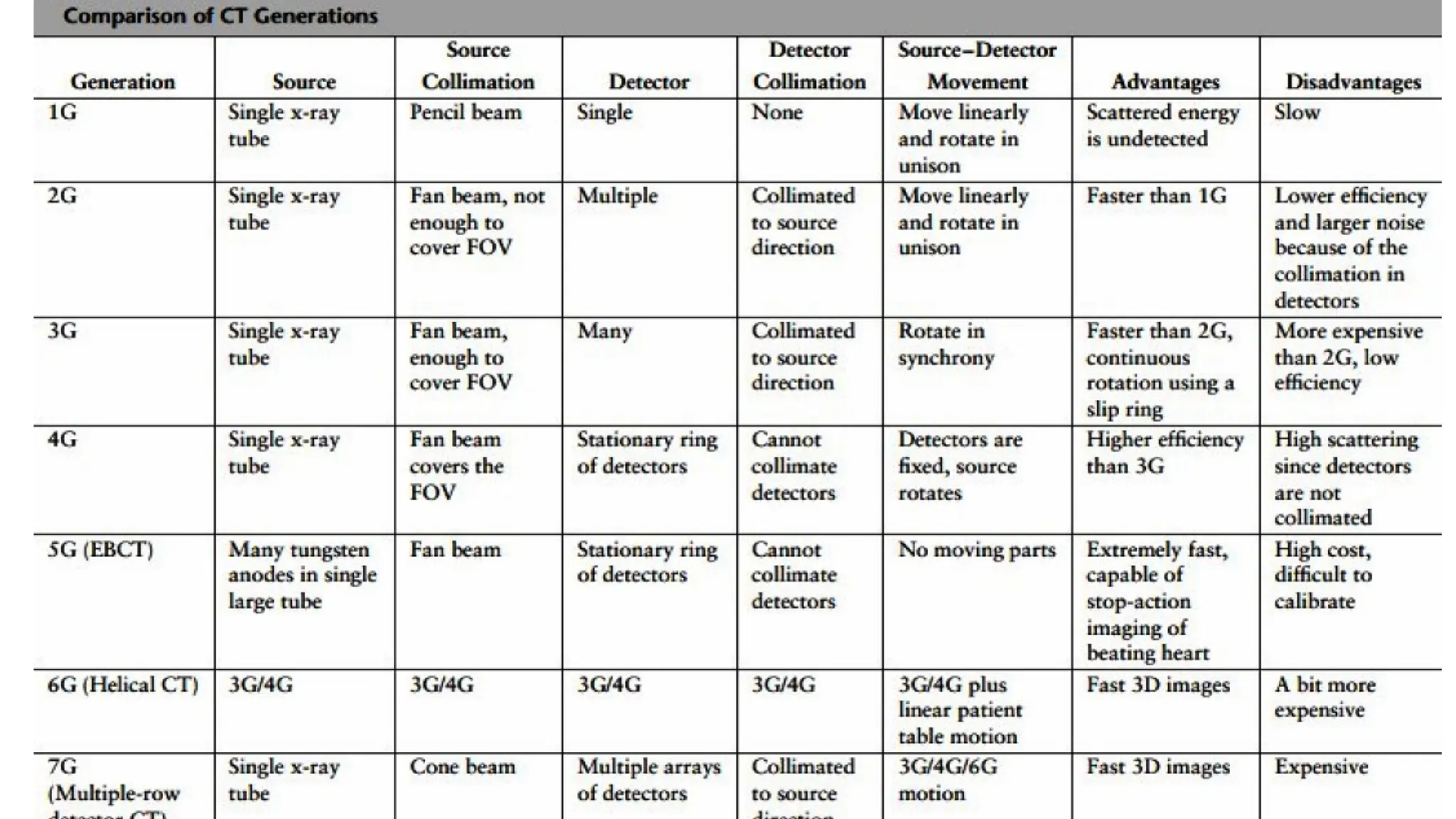
• First Generation—ParallelBeam Geometry
• The tube and detector move in a straight line, sampling the data 180
times. At the end of the travel, a 1° tilt is made and a new linear scan
begins.
• travels 180° around the patient’s position.- Traverse and Index
• results in 32,400 independent measurements of attenuation,
• Slow procedure and requires a typical scan time of 5 minutes.
13.
• Second Generation—FanBeam, Multiple Detectors:
• bank of detectors and a fan beam of X-rays
• Takes several profiles with each traverse and permits greater index
angles.
• 10° fan beam, provides 10 profiles, at 1° intervals, with each traverse
and then index through 10° before taking the next set of profiles.
• Therefore, a full set of 180 profiles can be obtained with 18 traverses.
• permits a reduction in the scan time 1 s for each traverse
• systems operating in the 8–20 s range.
14.
• Third Generation—FanBeam, Rotating Detectors:
• main obstacle to increase speed - multiple alterations between the translational and rotational
movement
• X-ray source and detectors mounted on a common frame and rotate around the patient, usually
through 360°.gives a wide fan beam, typically between 30° and 50°.
• The frame travels quite fast, so that a complete rotation takes only a few seconds.
• This configuration has two major disadvantages.
• Firstly, it has a fixed geometry. With a fan beam set for the largest patient, the arrangement
proves to be inefficient for smaller objects, particularly heads.
• Secondly, calibration of the detectors during scanning is not possible since the patient is always
within the beam.
• Therefore, any drifts or faults in the detection system tend to produce a significant degradation in
the picture quality.
15.
• Fourth Generation—FanBeam, Fixed Detectors:
• to overcome the difficulties in the rotating detectors configuration,
rotational machines -designed -only the X-ray source rotates within a
full circle of stationary detectors arranged around the patient
• The system employs as many as 2000 detectors to maintain a good
spatial resolution.
• The individual detectors are lined up practically without gaps,
• The system permits calibration during scanning, which eliminates
the problem of detector drift.
16.
• Fifth Generation—ScanningElectron Beam: The 0.7 to 1 second time
resolution limit of mechanical CT scanners makes phase-resolution
imaging of the beating heart possible only through manipulations
involving ECG triggering.
• The acquisition of all the cardiac phases within a single cardiac cycle
can only be realized using a data acquisition system which does not
contain any moving mechanical parts.
• One such system is the electron beam tomography
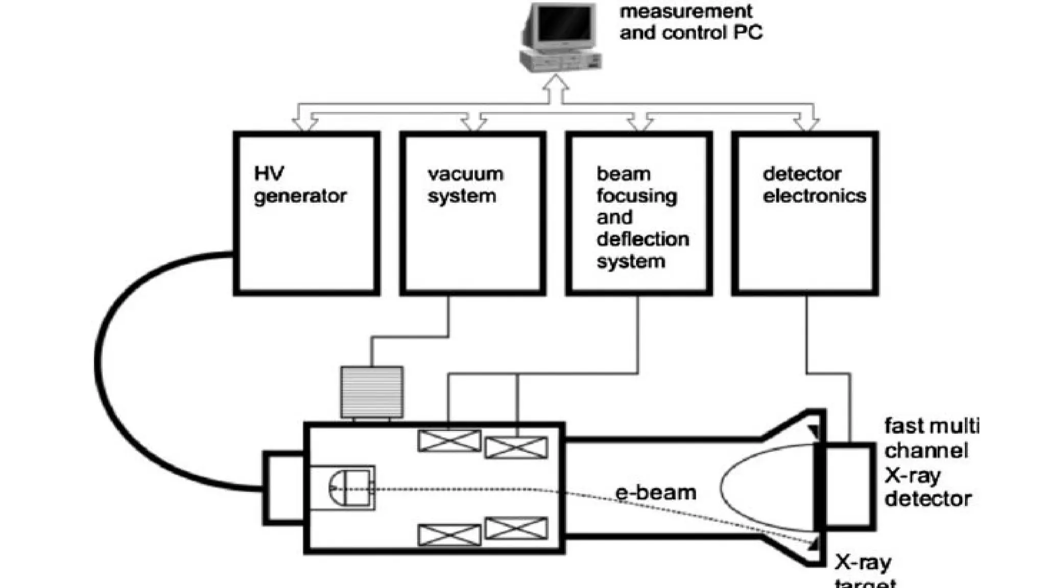
17.
• In electronbeam tomography, the electron beam sweeps back and forth through a
magnetic field.
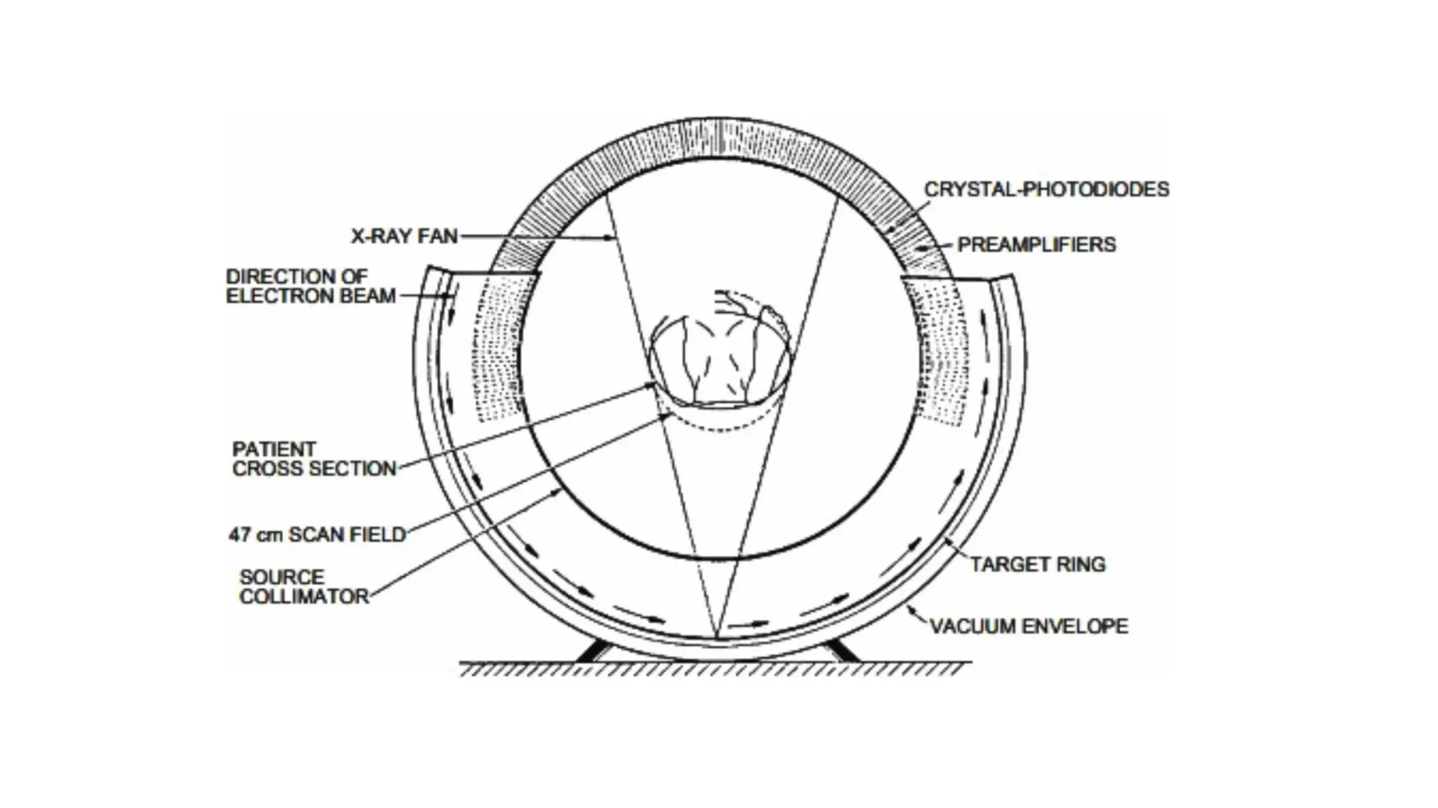
• The impact of the electron beam on a semi-circular tungsten array underneath the
patient generates the X-rays and the X-ray detectors are mounted on a semi-
circular array above the patient .
• Because an X-ray tube and X-ray detector are heavy moving parts, weighing as
much as 250 kg, it takes one second or more to take all the snapshots which are
later reconstructed to form an image of one slice of the body with a conventional
CT scanner.
• Since an electron beam can be moved back and forth through a magnetic field
very quickly, the time for scanning a slice can be of the order of 50 ms with
electron beam tomography
18.
• The detectorarray consists of two continuous ranges of 216° with 432 channels each.
• Luminascent crystals coupled to silicon photo-diodes are used.
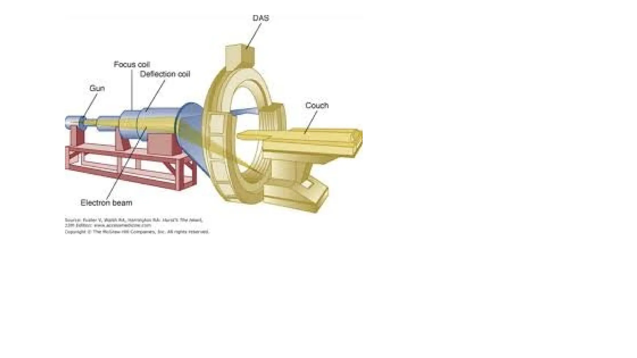
• The scanning electron beam emitted by an electron gun is accelerated by 130–140 kV,
electromagnetically focused and deflected over a target in a typical time of 50–100
ms.
• It was originally designed for cardiac examinations.
• The unit was equipped for this purpose with four anode rings and two detector rings
which enabled eight contiguous slices, an area of approximately 8 ¥ 8 mm, to be
scanned without movement of the patient.
• The basic difference between an electron beam scanner and conventional units is that
the patient is encircled by stationary anode rings which can thus be cooled directly.
23.
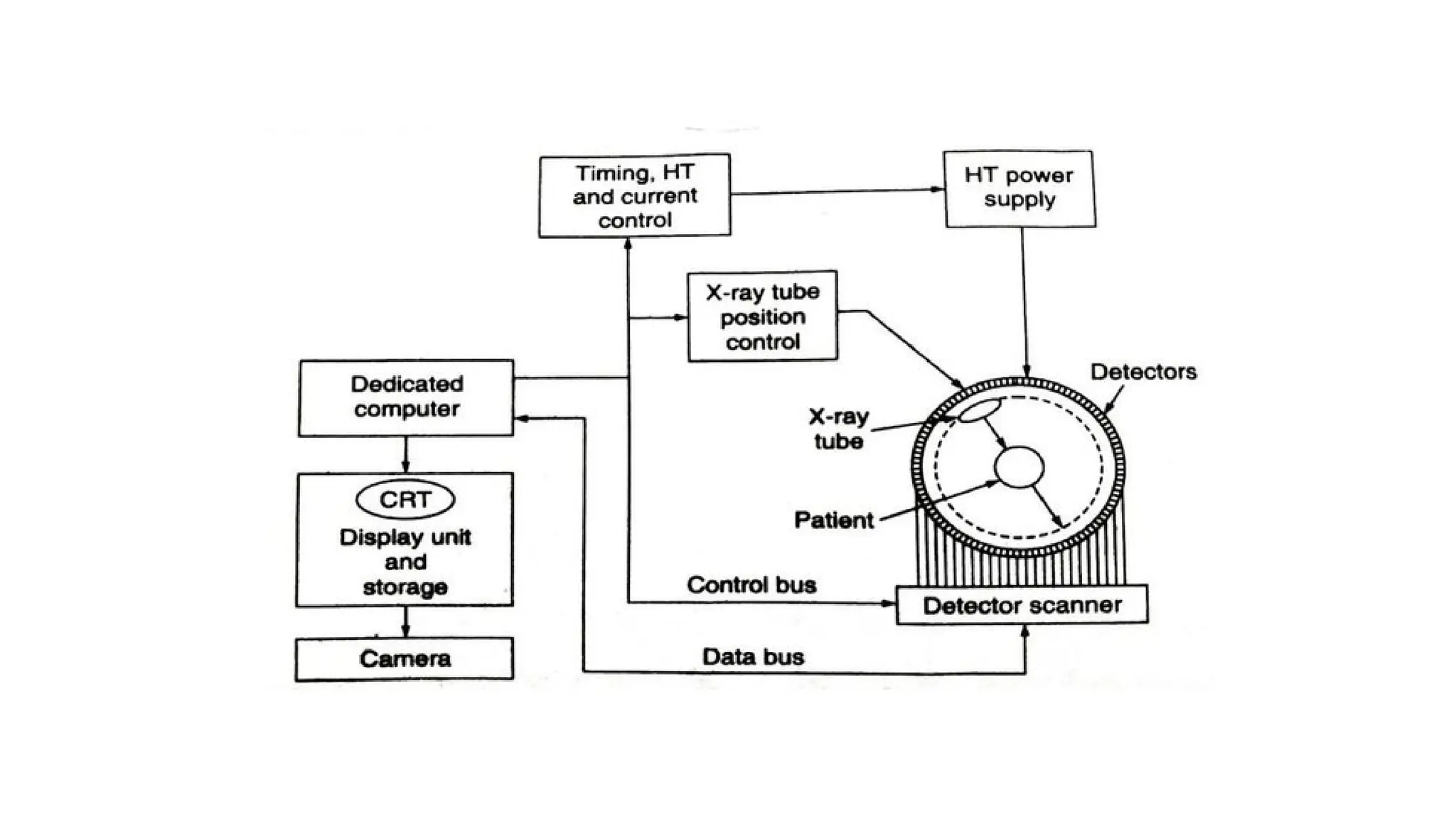
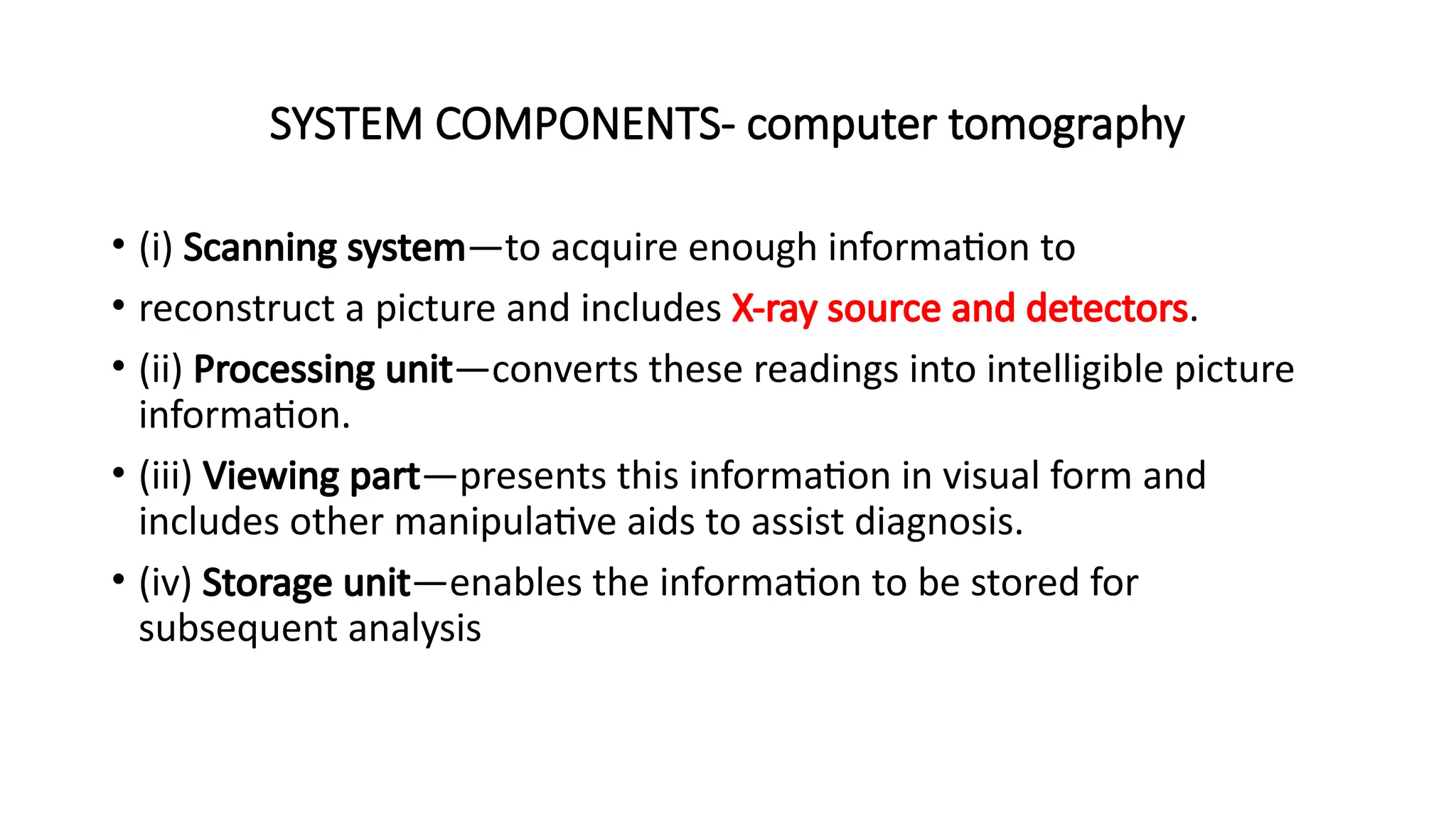
SYSTEM COMPONENTS- computertomography
• (i) Scanning system—to acquire enough information to
• reconstruct a picture and includes X-ray source and detectors.
• (ii) Processing unit—converts these readings into intelligible picture
information.
• (iii) Viewing part—presents this information in visual form and
includes other manipulative aids to assist diagnosis.
• (iv) Storage unit—enables the information to be stored for
subsequent analysis
24.
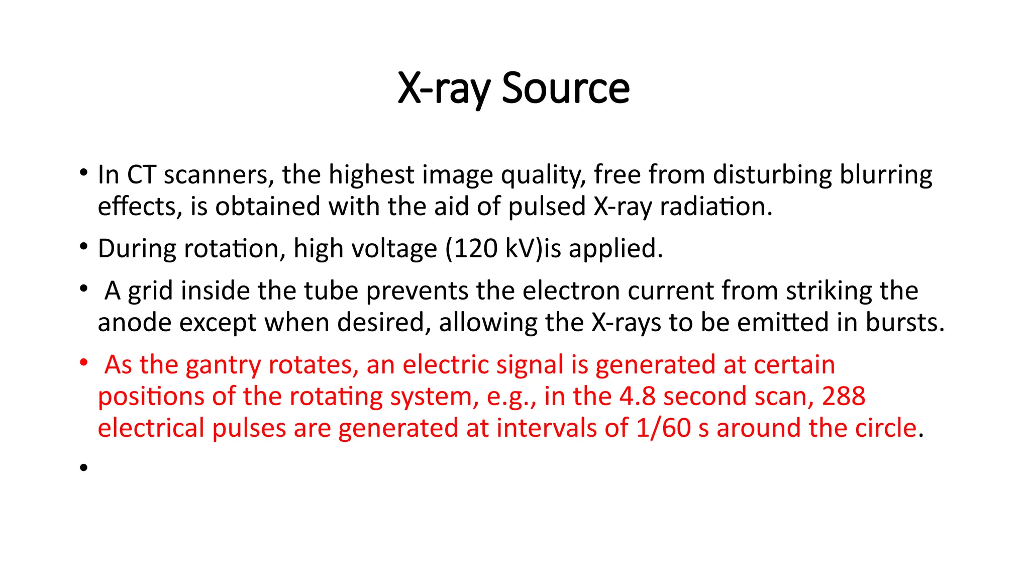
X-ray Source
• InCT scanners, the highest image quality, free from disturbing blurring
effects, is obtained with the aid of pulsed X-ray radiation.
• During rotation, high voltage (120 kV)is applied.
• A grid inside the tube prevents the electron current from striking the
anode except when desired, allowing the X-rays to be emitted in bursts.
• As the gantry rotates, an electric signal is generated at certain
positions of the rotating system, e.g., in the 4.8 second scan, 288
electrical pulses are generated at intervals of 1/60 s around the circle.
•
25.
• Each pulseturns on the X-rays for a short period of time.
• number of pulses, pulse duration and tube current determine the
dose to the patient.
• For producing a fan beam, a collimator is incorporated between the X-
ray tube and the patient
• A filter inside the collimator housing shapes the beam intensity.
• in body scanners, there are two filters, one for bodies and the other
for heads -automatically selected by the computer.
• Two main types of X-ray tubes are used for computed tomography.
26.
• A collimeterassembly controls the width of the fan beam between 1.0
and 10mm, which, in turn, controls the width of the imaged slice.
• All modern systems use high frequency generators, typically operating
between 5 and 50 kHz.
• A heat exchanger on the rotating gantry is used to cool the tube.
• Spiral scanning especially places heavy demands on the heat storage
capacity and cooling rate of the X-ray tube.
• A new X-ray tube based on liquid-metal-filled, spiral– groove bearings
which allow very high continuous power, has been developed to meet
this requirement.
27.
• Two maintypes of X-ray tubes are used for computed tomography
• oil cooled fixed anode line—focus continuous tube, used in first and second
generation CT scanners. They utilized a tungsten target with a target angle of
about 20 degrees.
• Rotating anode air-cooled pulsed X-ray source.
• These tubes have a higher power capability for exposure times in the 2–20
second range. The power requirements of these tubes are generally variable
within 100–160 kV.
• Typical power requirements of these tubes are 120 kV at 200–500 mA, producing
X-rays with an energy spectrum ranging from approximately 30–120 keV.
28.
COLLIMATION
• After transmissionthrough the patient, the x-ray beam is collimated
to confine the transmission measurement to a slice with a thickness
of a few millimeters.
• Collimation also serves to reduce scattered radiation to less than 1%
of the primary beam intensity.
• The height of the collimator defines the thickness of the CT slice.
• This height, when combined with the area of a single picture element
(pixel) in the display, defines the three-dimensional volume element
(voxel) in the patient corresponding to the two-dimensional pixel of
the display.
29.
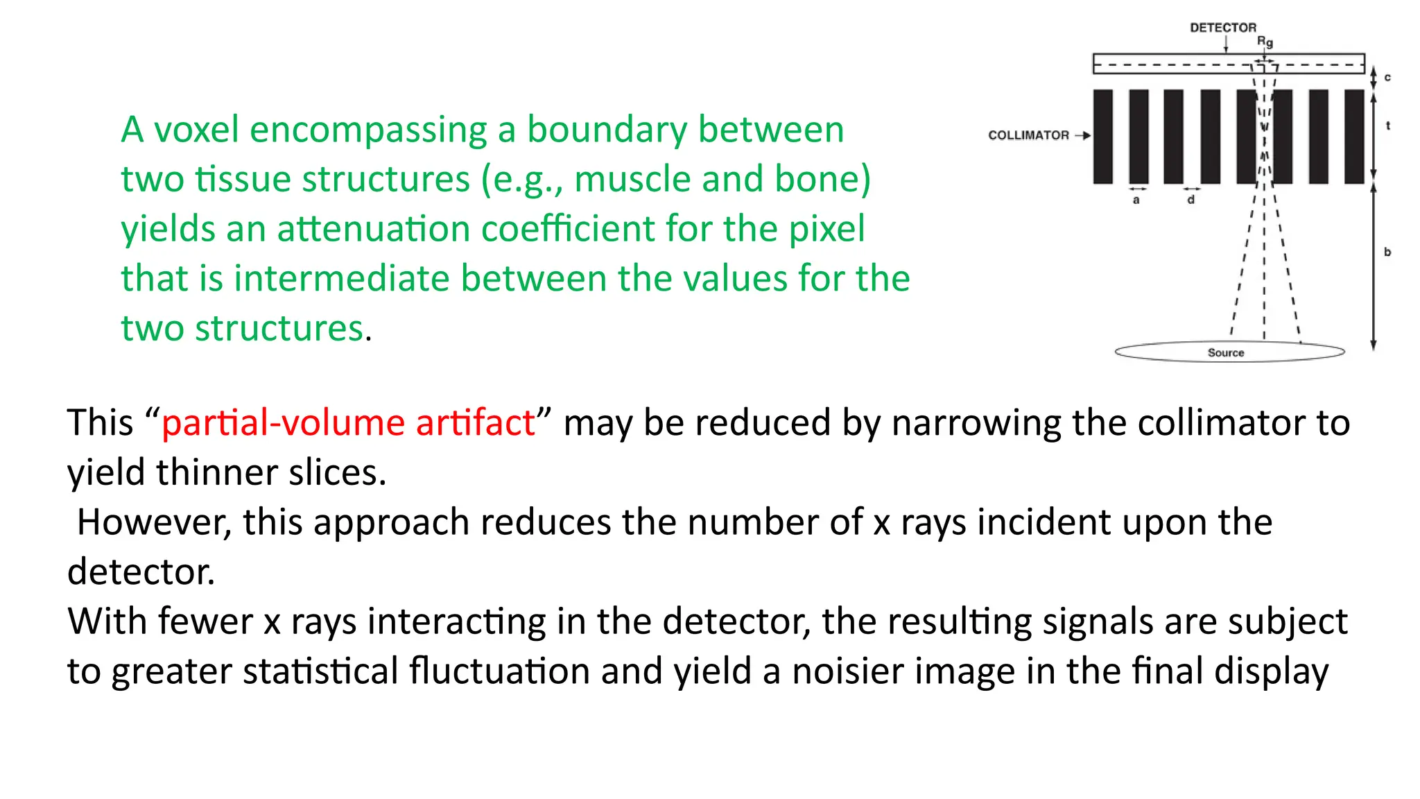
A voxel encompassinga boundary between
two tissue structures (e.g., muscle and bone)
yields an attenuation coefficient for the pixel
that is intermediate between the values for the
two structures.
This “partial-volume artifact” may be reduced by narrowing the collimator to
yield thinner slices.
However, this approach reduces the number of x rays incident upon the
detector.
With fewer x rays interacting in the detector, the resulting signals are subject
to greater statistical fluctuation and yield a noisier image in the final display
30.
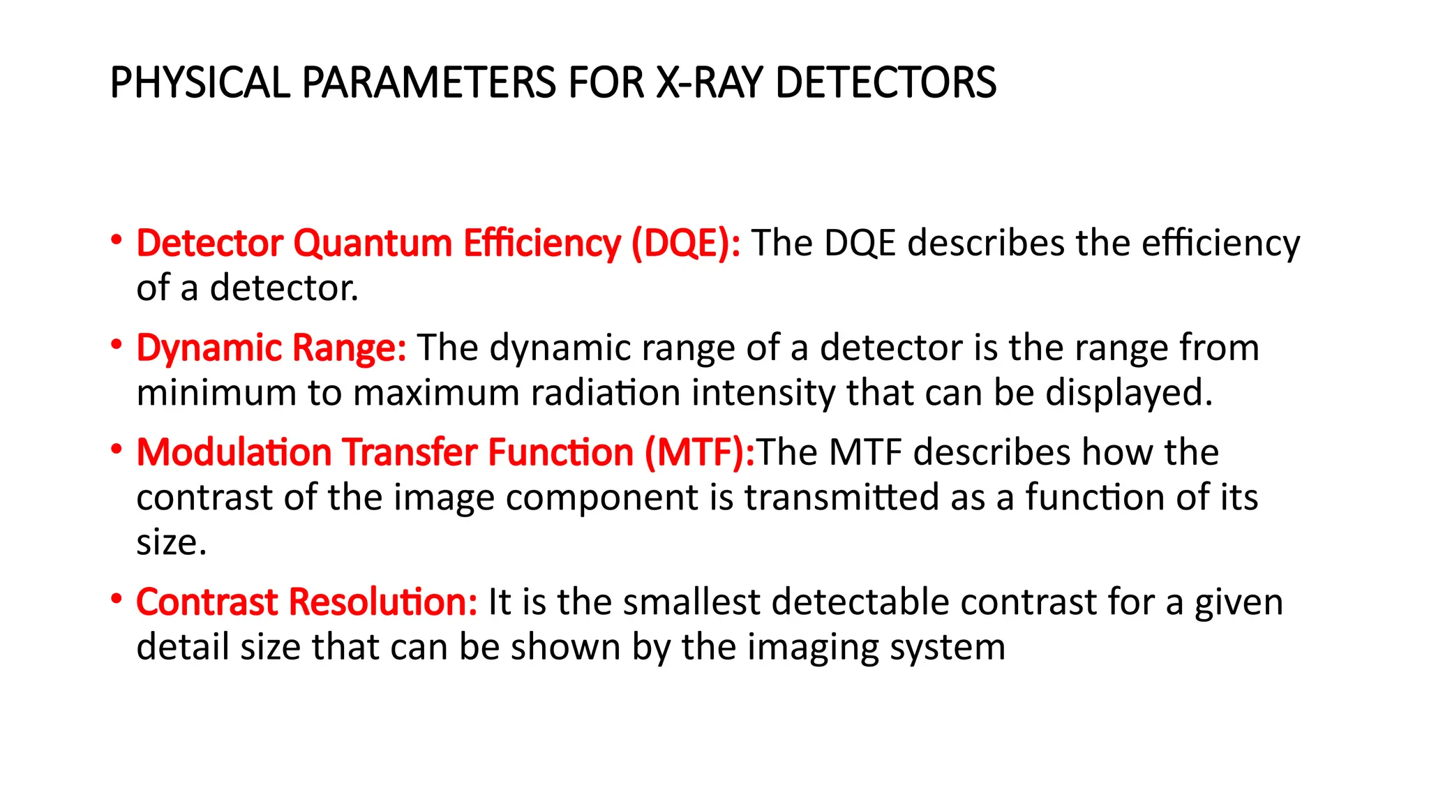
PHYSICAL PARAMETERS FORX-RAY DETECTORS
• Detector Quantum Efficiency (DQE): The DQE describes the efficiency
of a detector.
• Dynamic Range: The dynamic range of a detector is the range from
minimum to maximum radiation intensity that can be displayed.
• Modulation Transfer Function (MTF):The MTF describes how the
contrast of the image component is transmitted as a function of its
size.
• Contrast Resolution: It is the smallest detectable contrast for a given
detail size that can be shown by the imaging system
31.
Detectors
• Three typesof detectors used in computer tomography
• Xenon gas ionization detectors.
• scintillator-photomultiplier detectors
• SCINTILLARC detector system
32.
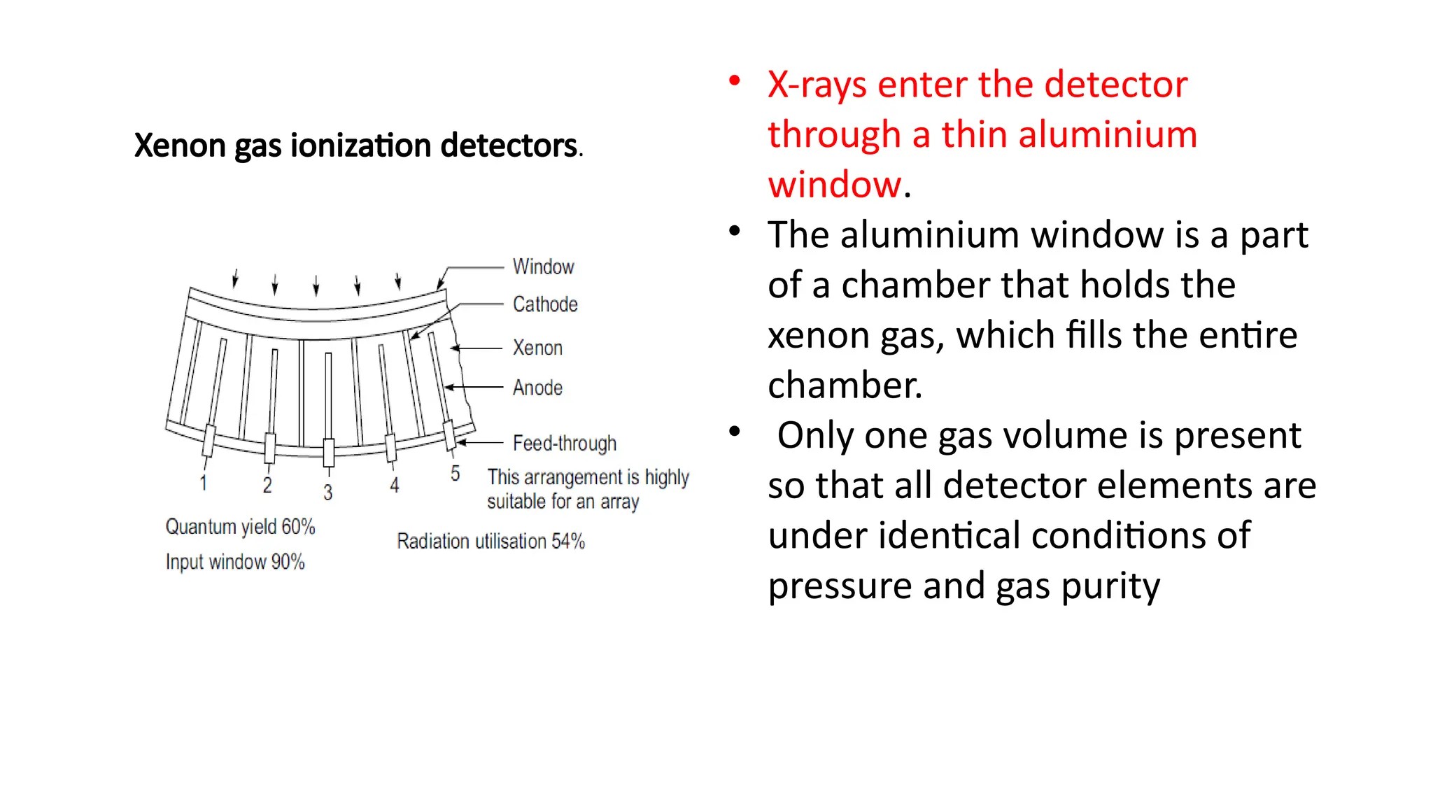
Xenon gas ionizationdetectors.
• X-rays enter the detector
through a thin aluminium
window.
• The aluminium window is a part
of a chamber that holds the
xenon gas, which fills the entire
chamber.
• Only one gas volume is present
so that all detector elements are
under identical conditions of
pressure and gas purity
33.
• The detectorvolume is separated into several hundred elements or cells.
• In a typical scanner, these cells subtend the 42 cm maximum patient
diameter. There are 511 data cells and 12 reference cells for
simultaneous data collection per view.
• The detector cells are defined by thin tungsten plates.
• Every other plate is connected to a common 500 V power supply. The
alternate plates are collector plates and are individually connected to
electronic amplifiers.
• X-rays which enter the gas volume between the plates interact with
xenon, producing positive ions and negative electrons.
34.
• The positivevoltage accelerates the ions to the collector plate and
produces an electric current in the amplifier.
• The resulting current through the electrode is a measure of the
incident X-ray intensity
35.
scintillator-photomultiplier detectors
• scintillationdetectors are made of sodium iodide, bismuth germanite
and cesium iodide crystals.
• The crystals transform the kinetic energy of the secondary electrons
into flashes of light which can be detected by a photomultiplier and
converted to a useable electric signal.
36.
scintillator-photomultiplier detectors
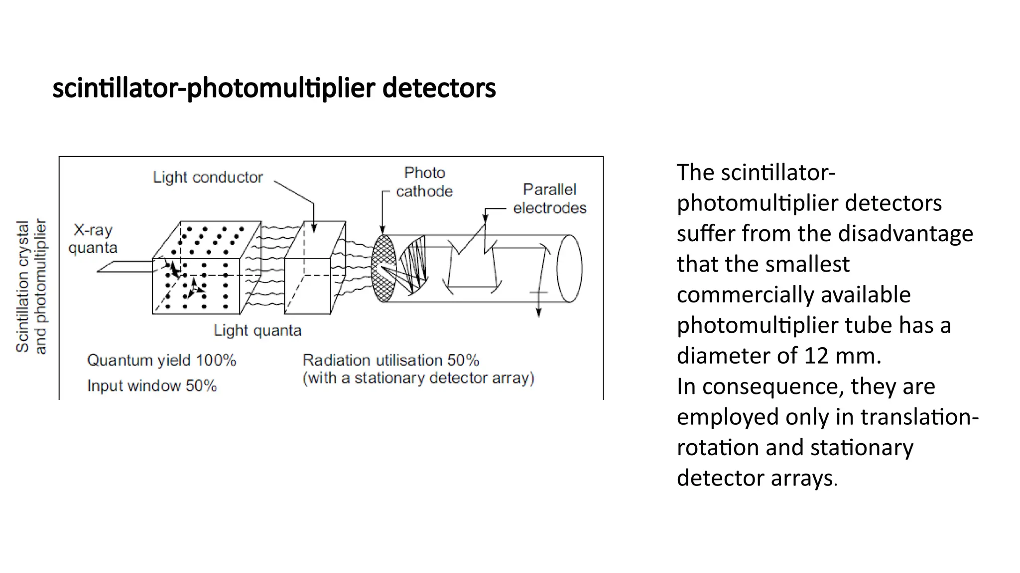
The scintillator-
photomultiplierdetectors
suffer from the disadvantage
that the smallest
commercially available
photomultiplier tube has a
diameter of 12 mm.
In consequence, they are
employed only in translation-
rotation and stationary
detector arrays.
37.
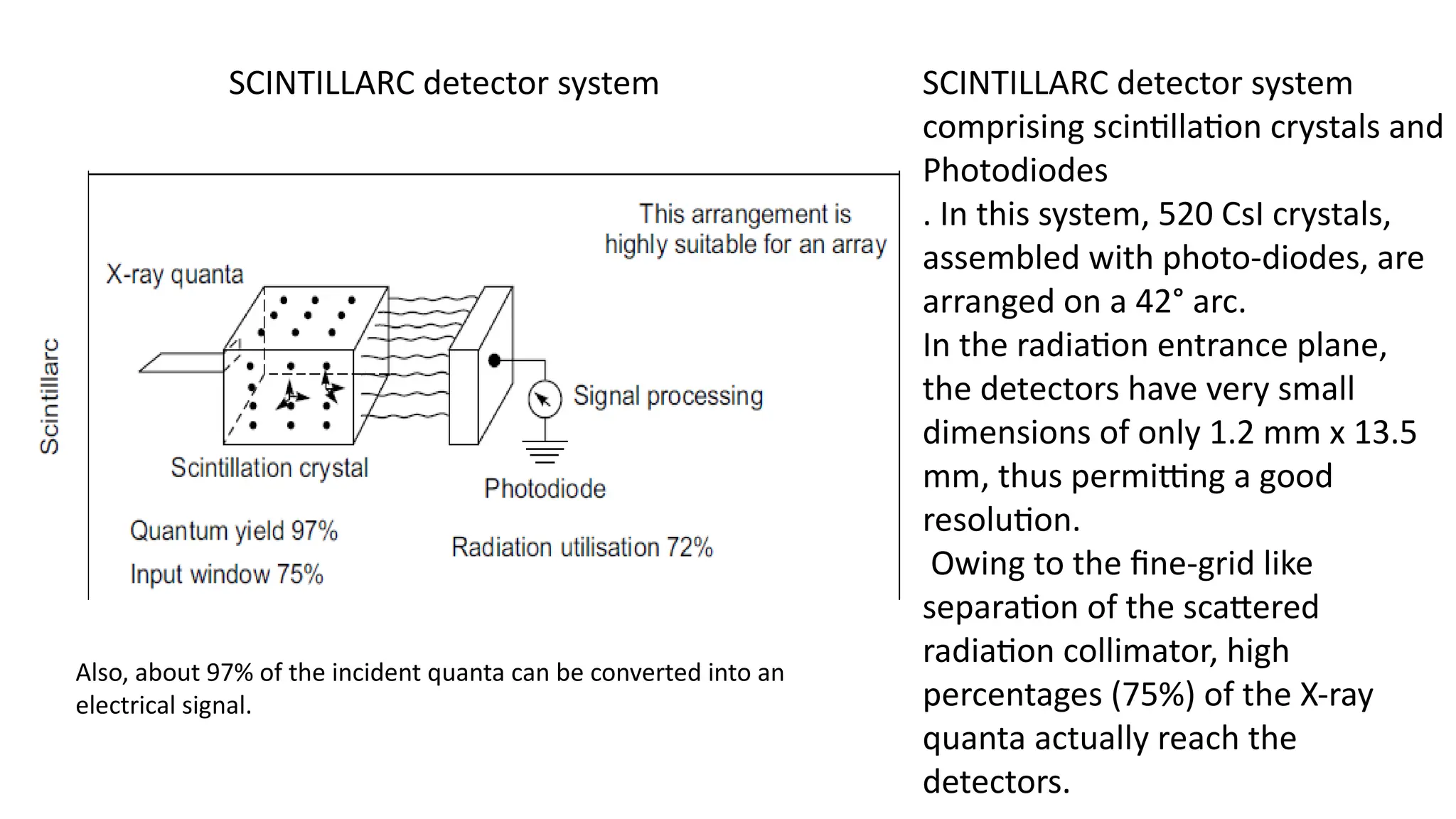
SCINTILLARC detector systemSCINTILLARC detector system
comprising scintillation crystals and
Photodiodes
. In this system, 520 CsI crystals,
assembled with photo-diodes, are
arranged on a 42° arc.
In the radiation entrance plane,
the detectors have very small
dimensions of only 1.2 mm x 13.5
mm, thus permitting a good
resolution.
Owing to the fine-grid like
separation of the scattered
radiation collimator, high
percentages (75%) of the X-ray
quanta actually reach the
detectors.
Also, about 97% of the incident quanta can be converted into an
electrical signal.
38.
• The outputfrom each photodiode is a current proportional to the
light striking the diode.
• These currents can be directly converted to a voltage by a low-noise
transimpedance amplifier, or active integrator op-amp circuit to
produce a voltage output
39.
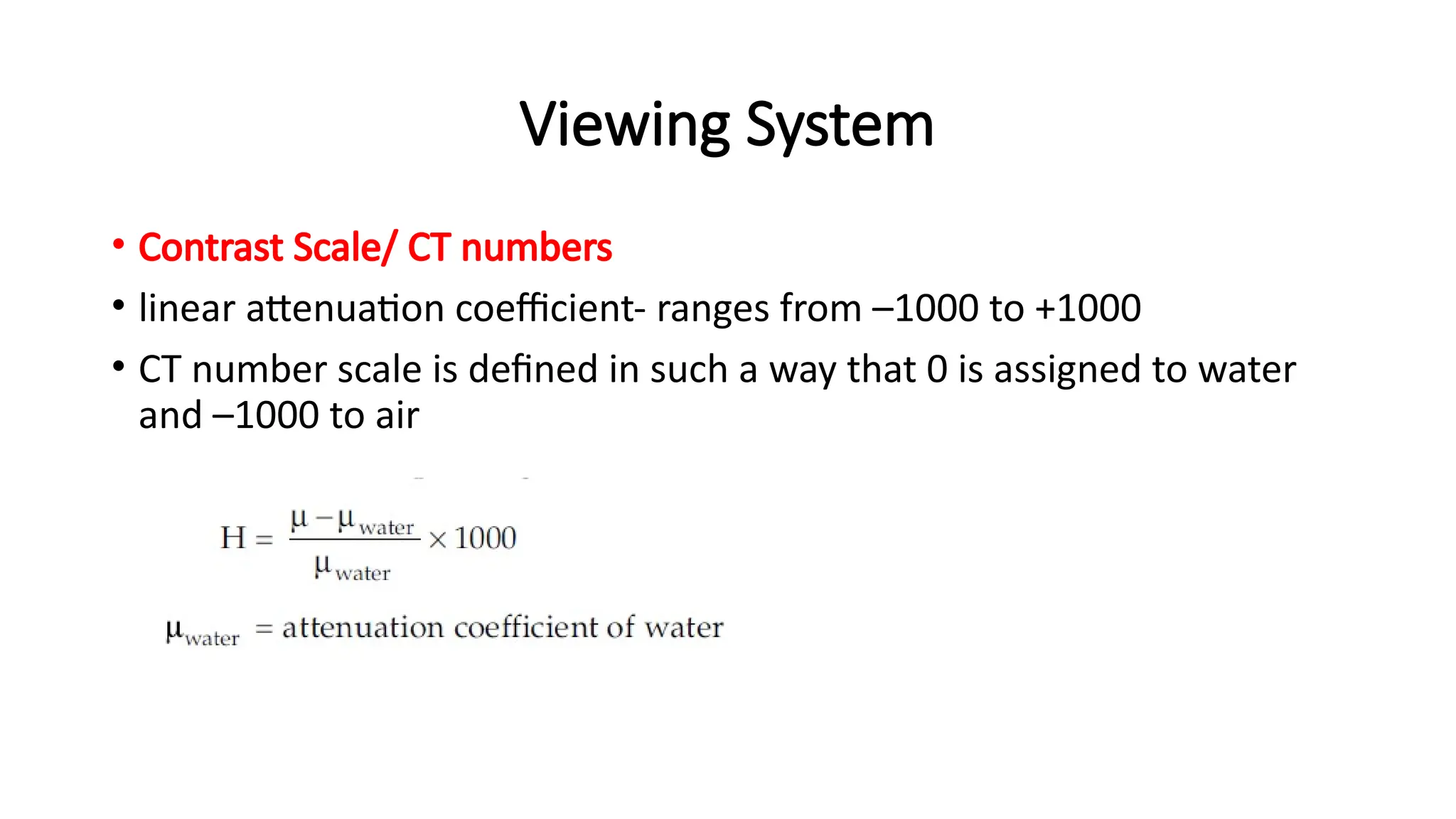
Viewing System
• ContrastScale/ CT numbers
• linear attenuation coefficient- ranges from –1000 to +1000
• CT number scale is defined in such a way that 0 is assigned to water
and –1000 to air
40.
Viewing System
• Atelevision monitor is used to portray CT numbers as a gray-scale visual display.
• This viewing device contains a contrast enhancement feature that superimposes the
shades of gray available in the display device (i.e., the dynamic range of the display)
over the range of CT numbers of diagnostic interest
• . Control of image contrast with the contrast enhancement feature is essential in x-
ray CT because the electron density, and therefore the x-ray attenuation, are
remarkably similar for most tissues of diagnostic interest.
• The viewing console of the CT scanner may contain auxiliary features such as image
magnification, quantitative and statistical data display, and patient identification
data.
• Also, many scanners permit the display of coronal and sagittal images by combining
reconstruction data for successive slices through the body.
41.
SPIRAL /HELICAL SCANNING
•This is a scanning technique in which the X-ray tube rotates continuously around
the patient while the patient is continuously translated through the fan beam.
• The focal spot therefore, traces a helix around the patient.
• The projection data thus obtained allow for the reconstruction of multiple
contiguous images.
• This operation is often referred to as helix, spiral, volume, or three-dimensional
CT scanning.
• This technique has been developed for acquiring images with faster scan times
and to obtain fast multiple scans for three-dimensional imaging to obtain and
evaluate the ‘volume’ at different locations.
42.
• Figure illustratesthe spiral scanning technique, which causes the focal spot
to follow a spiral path around the patient.
• Multiple images are acquired while the patient is moved through the gantry
in a smooth continuous motion rather than stopping for each image.
• The projection data for multiple images covering a volume of the patient
can be acquired in a single breath hold at rates of approximately one slice
per second.
• The reconstruction algorithms are more complex because they need to
account for the spiral or helical path traversed by the X-ray source around
the patient.
43.
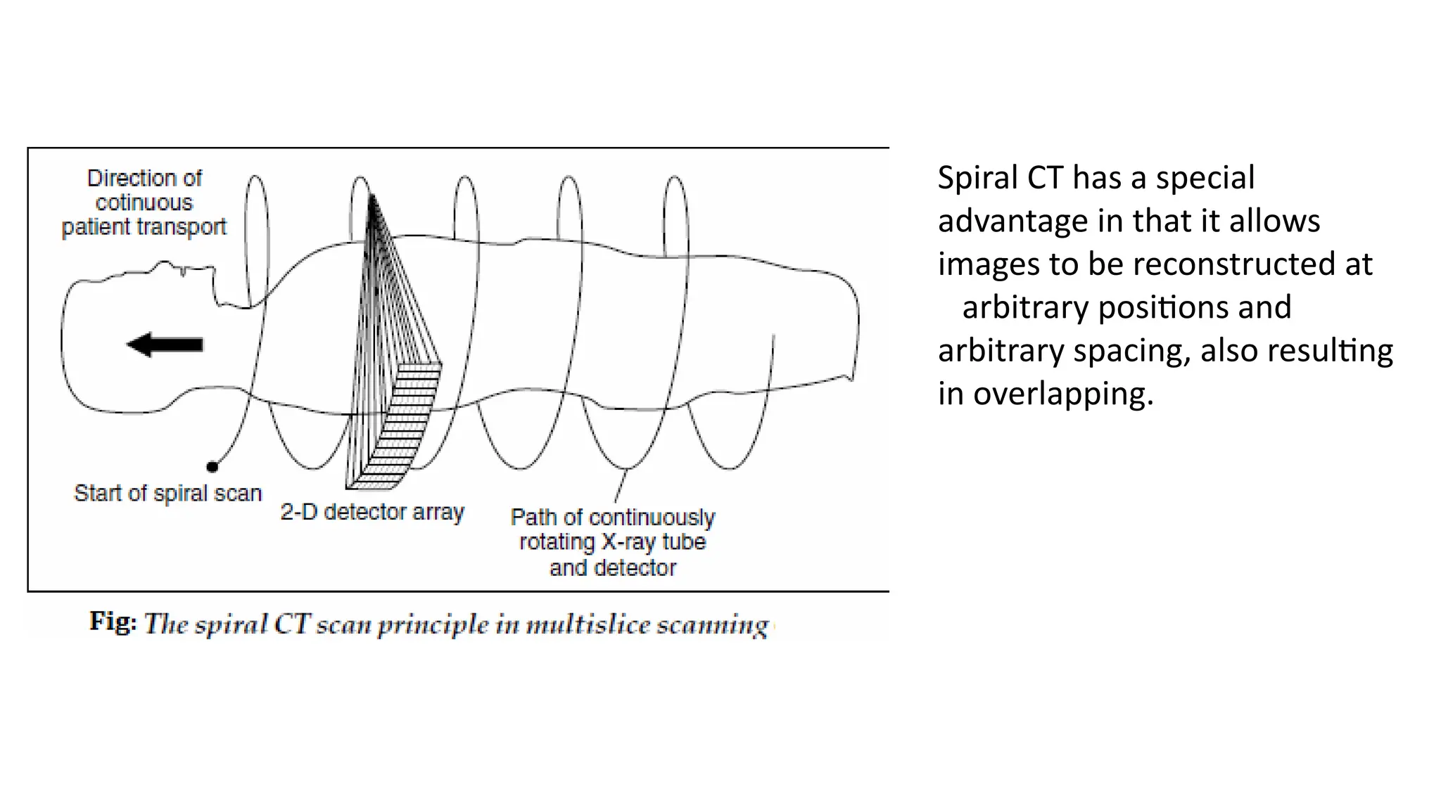
Spiral CT hasa special
advantage in that it allows
images to be reconstructed at
arbitrary positions and
arbitrary spacing, also resulting
in overlapping.
44.
• The continuousacquisition of whole sections of the body, largely
independent of respiration or movement, also permit the reliable
localization of small lesions.
• Continuous data acquisition in the trunk of the body with the
possibility of the reconstruction of overlapping slices are not
previously achieved.
• A fundamental difference between and potential disadvantage of
spiral CT as compared with conventional CT is that slice sensitivity
profiles are blessed by the movement of the patient in the Z direction.
•
45.
• The degreeof blurring depends upon the speed at which the patient
is moved and has a corresponding influence on the spatial resolution
perpendicular to the scan slice.
• However, this can be largely minimized by using suitable de-
blurring software.
• In the normal case, this blurring is almost negligible if the selected
table feed per 360° revolution is the same as the slice thickness.
• The SOMATOM Plus from Siemens and Toshiba 900S were the first
units which offered spiral CT in 1987 and for the first time, made
possible scan times of only 1 second per 360 degree scan.
46.
• In thisapproach, image acquisition time is decreased significantly by connecting
the tube voltage cables through a “slip ring” or sliding contact mounted on the
rotating gantry of the unit.
• With slip ring technology, the x-ray tube rotates while the patient table moves
without stopping.
• Hence, the patient is moved continuously through the gantry during the study,
and the x-ray beam maps out a helical or spiral path in the patient,
• Potential advantages of the spiral CT technique include a reduction of patient
motion and a general increase in patient throughput
•
47.
• A greatervolume of the patient may bescanned during the passage of contrast media,
permitting reduction in the volume of contrast needed.
• Also, the continuity of data along the axis of the patient (i.e., absence of gaps between scans)
improves the quality of three-dimensional reconstruction.
• In single-slice CT scanning, pitch is defined as the patient couch movement per rotation
divided by the slice thickness.
• In multislice CT, this definition is altered slightly to patient couch movement per rotation
divided by the beam width.
• Low pitch (i.e., small increments of couch movement) yields improved spatial resolution
along the long axis (Z axis) of the patient, but also results in higher patient doses and longer
imaging times.
• For pitches greater than unity, the dose to the patient is less, but data must be interpolated
so that resolution along the Z axis is preserved.
48.
Slip ring technology
•Slip ring technology in CT scanners for enabling continuous rotation of
the gantry and facilitates helical scanning
• It allows for the transfer of power and data between the stationary
and rotating parts of the scanner without the need for physical cables
• This technology enables faster and more efficient data acquisition,
leading to higher quality images and expanded diagnostic capabilities
49.
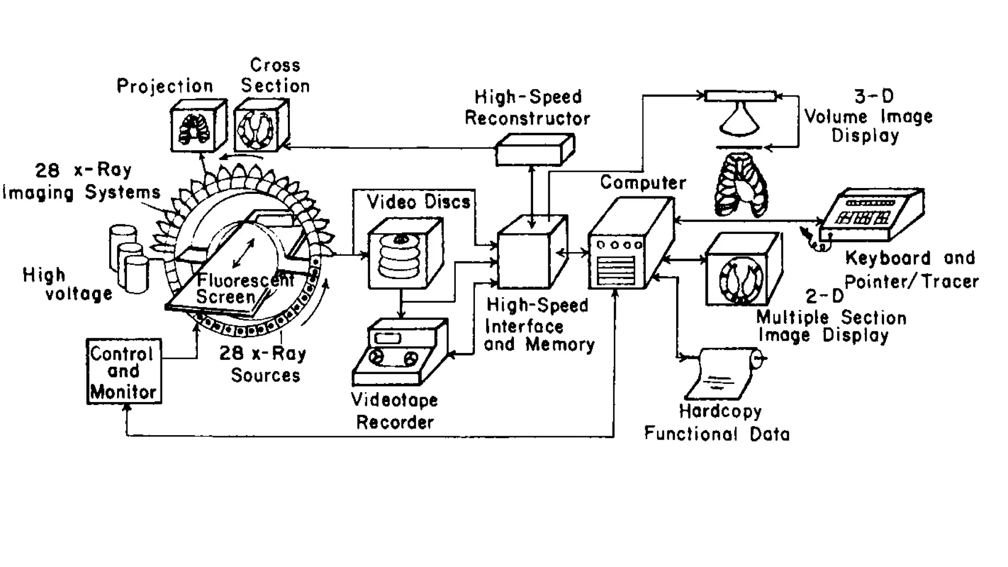
ULTRAFAST CT SCANNERS
•Dynamic spatial reconstructor (DSR),
• incorporates 28 gantry-mounted x-ray tubes over a 180-degree arc
and used an equal number of image intensifier assemblies mounted
on the opposite semicircle of the gantry.
• The entire assembly rotated about the patient at a rate of 15 rpm to
provide 28 views every 1/60 second.
• Working models of the system were built for research, but the
technical complexity and cost prevented the DSR from being
marketed commercially
51.
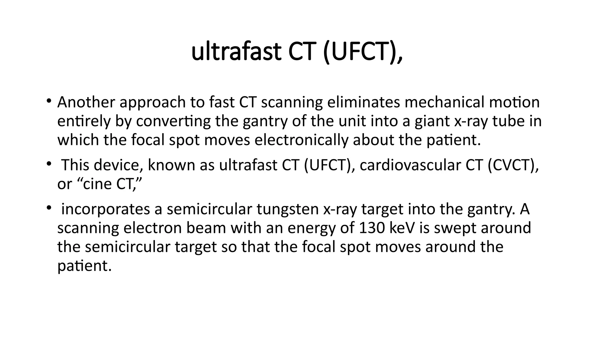
ultrafast CT (UFCT),
•Another approach to fast CT scanning eliminates mechanical motion
entirely by converting the gantry of the unit into a giant x-ray tube in
which the focal spot moves electronically about the patient.
• This device, known as ultrafast CT (UFCT), cardiovascular CT (CVCT),
or “cine CT,”
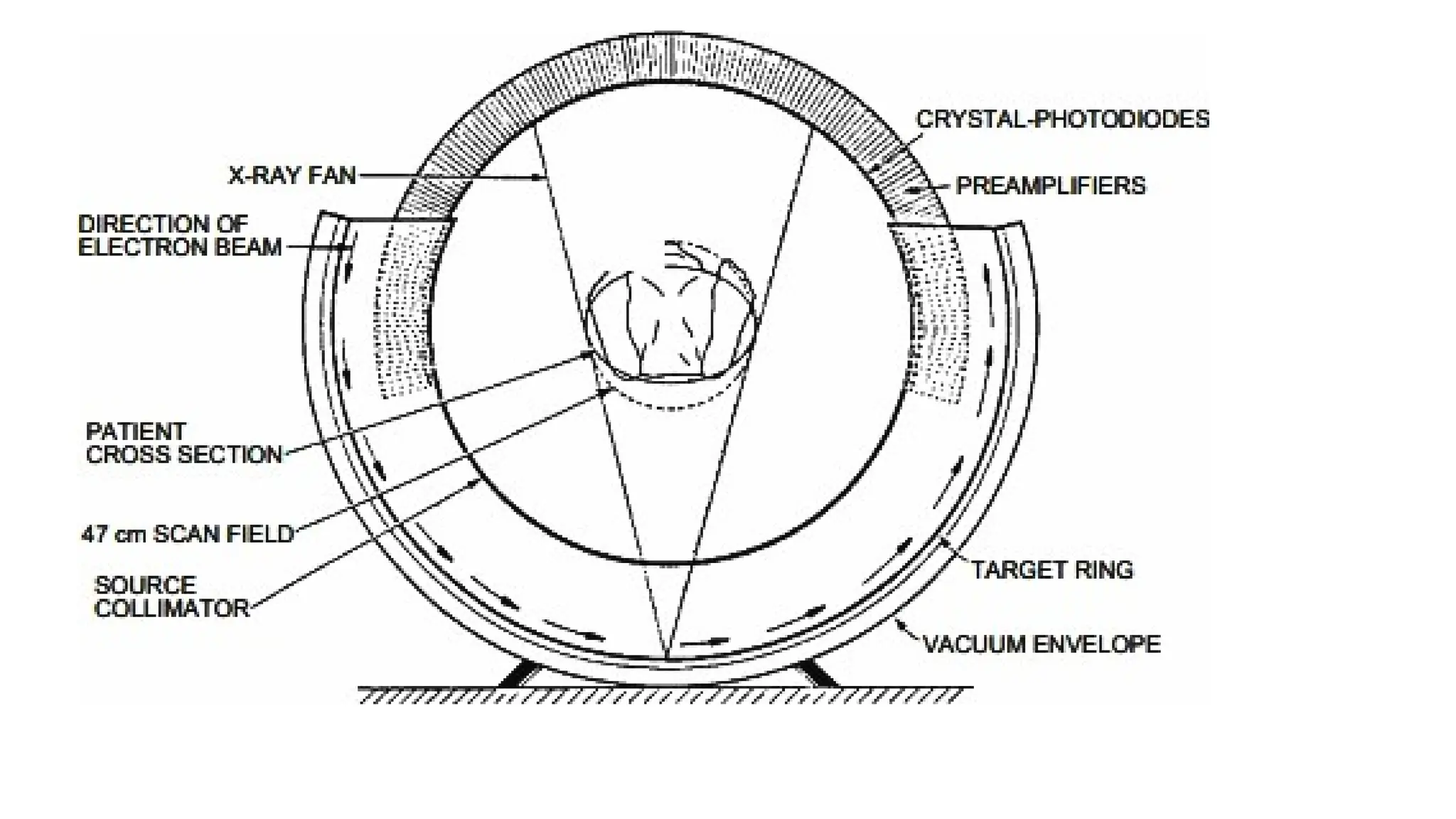
• incorporates a semicircular tungsten x-ray target into the gantry. A
scanning electron beam with an energy of 130 keV is swept around
the semicircular target so that the focal spot moves around the
patient.
53.
• A stationarysemicircular bank of detectors records the x-ray
transmission in a fashion similar to that of a fourth-generation
scanner.
• Because of the speed with which the electron beam may be steered
magnetically, a scan may be accomplished in as little as 50 ms and
repeated after a delay of 9 ms to yield up to 17 images per second.
• By using four target rings and two detector banks, eight slices of the
patient may be imaged without moving the patient
54.
Advantages of SpiralCompared with Conventional Computed
Tomography
• Faster image acquisition
• • Quicker response to contrast media
• • Fewer motion artifacts
• • Improved two-axis resolution
• • Physiological imaging
• • Improved coronal, sagittal, and 3D imaging
• • Less partial volume artifact
• • No misregistration
55.
Processing System
• DataAcquisition System:
• Processing electronic system should have a high dynamic range
• The dynamic range defines the ratio of the smallest, just detectable
signal to the largest signal without causing saturation. The dynamic
range in a typical situation is 1:4,00,000.
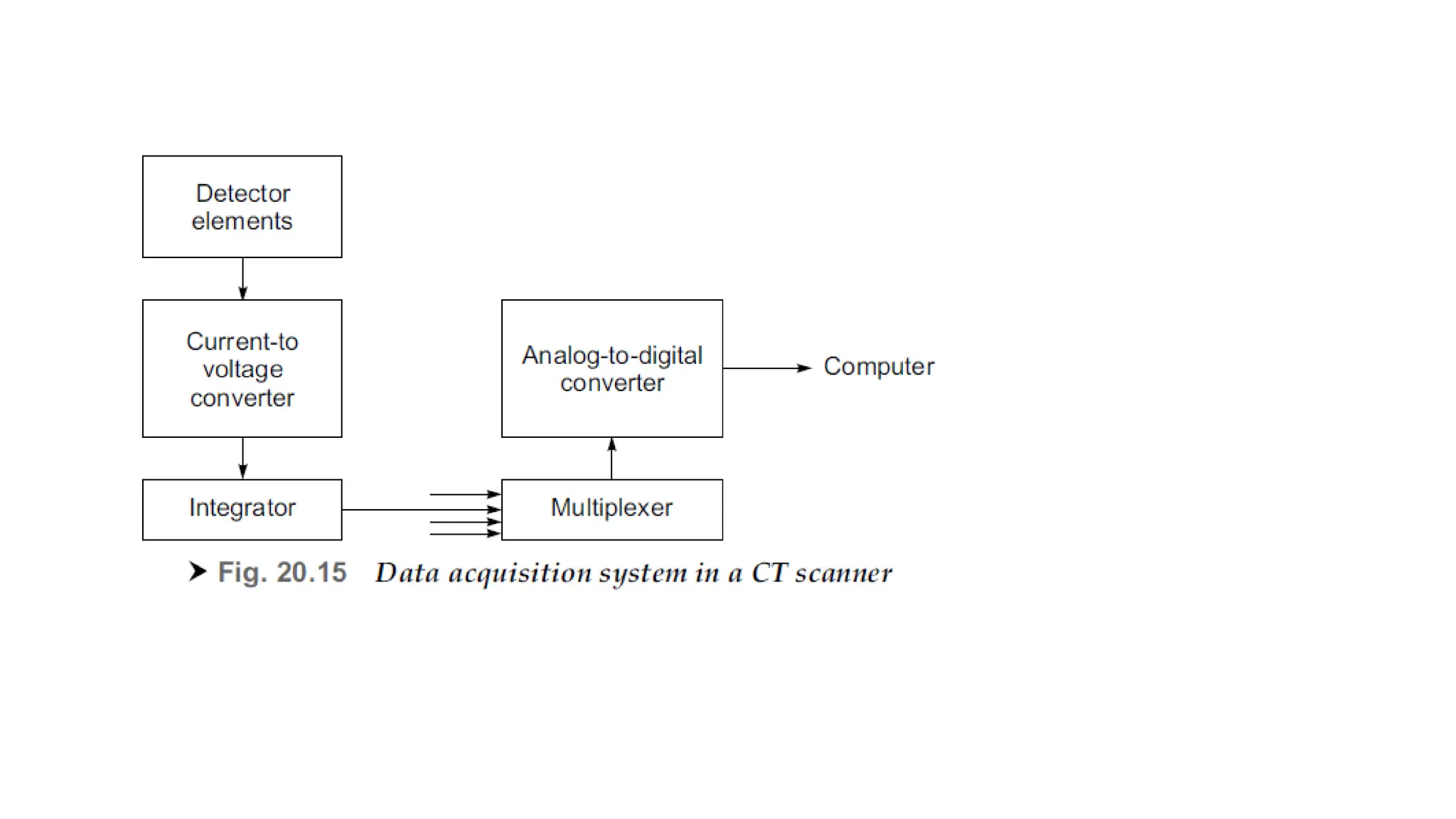
• It consists of precision pre-amplifiers, current to voltage converter,
analog integrators, multiplexers and analog-to-digital converters.
• Data transfer rates of the order of 10 Mbytes/s are generally required
57.
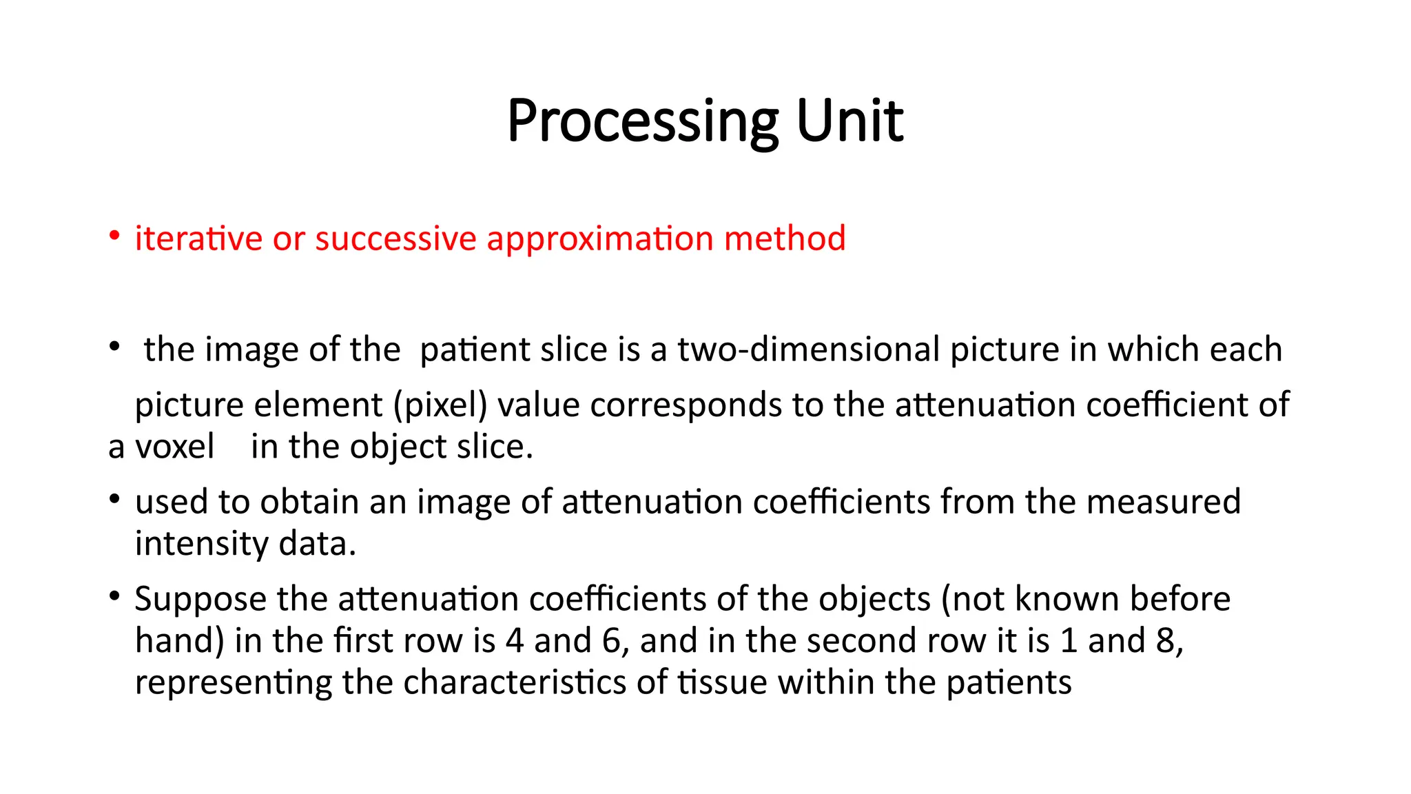
Processing Unit
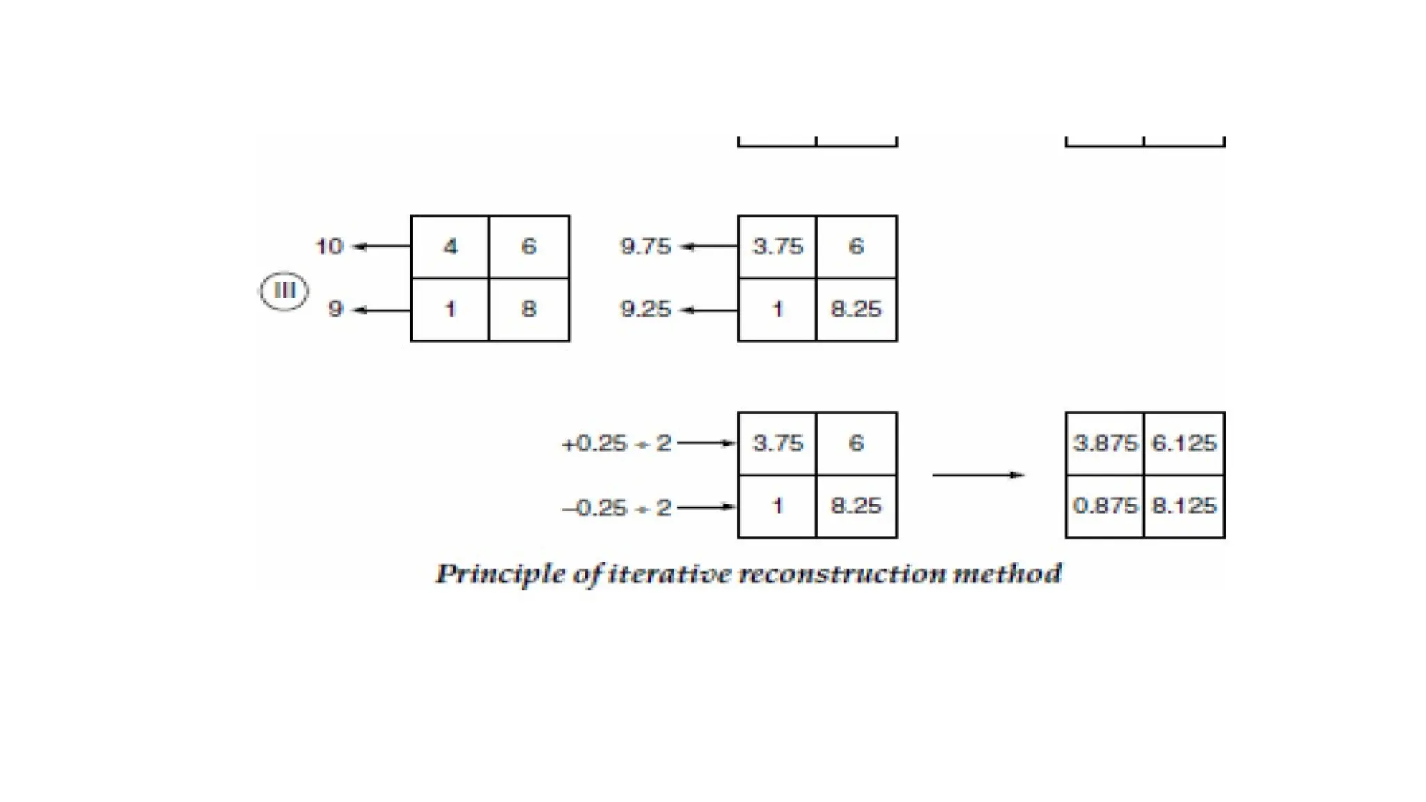
• iterativeor successive approximation method
• the image of the patient slice is a two-dimensional picture in which each
picture element (pixel) value corresponds to the attenuation coefficient of
a voxel in the object slice.
• used to obtain an image of attenuation coefficients from the measured
intensity data.
• Suppose the attenuation coefficients of the objects (not known before
hand) in the first row is 4 and 6, and in the second row it is 1 and 8,
representing the characteristics of tissue within the patients
58.
Image reconstruction methods
•reconstruction methods can be classified into the following three
major techniques
• Back projection, which is analogous to a graphic reconstruction;
• Filtered Back projection.
• Iterative methods, which implement some form of algebraic solution;
• Analytical methods, where an exact formula is used.
59.
• The informationreceived by the computer from the scanning gantry
needs to be processed for reconstructing the pictures.
• The data from the gantry contains information on:
• Positional information, such as which traverse is being performed and
how far the scanning frame is along its traverse;
• Absorption information including the values of attenuation coefficient
from the detectors;
• Reference information that is obtained from the reference detector that
monitors the X-ray output
• Calibration information that is obtained at the end of each traverse.
60.
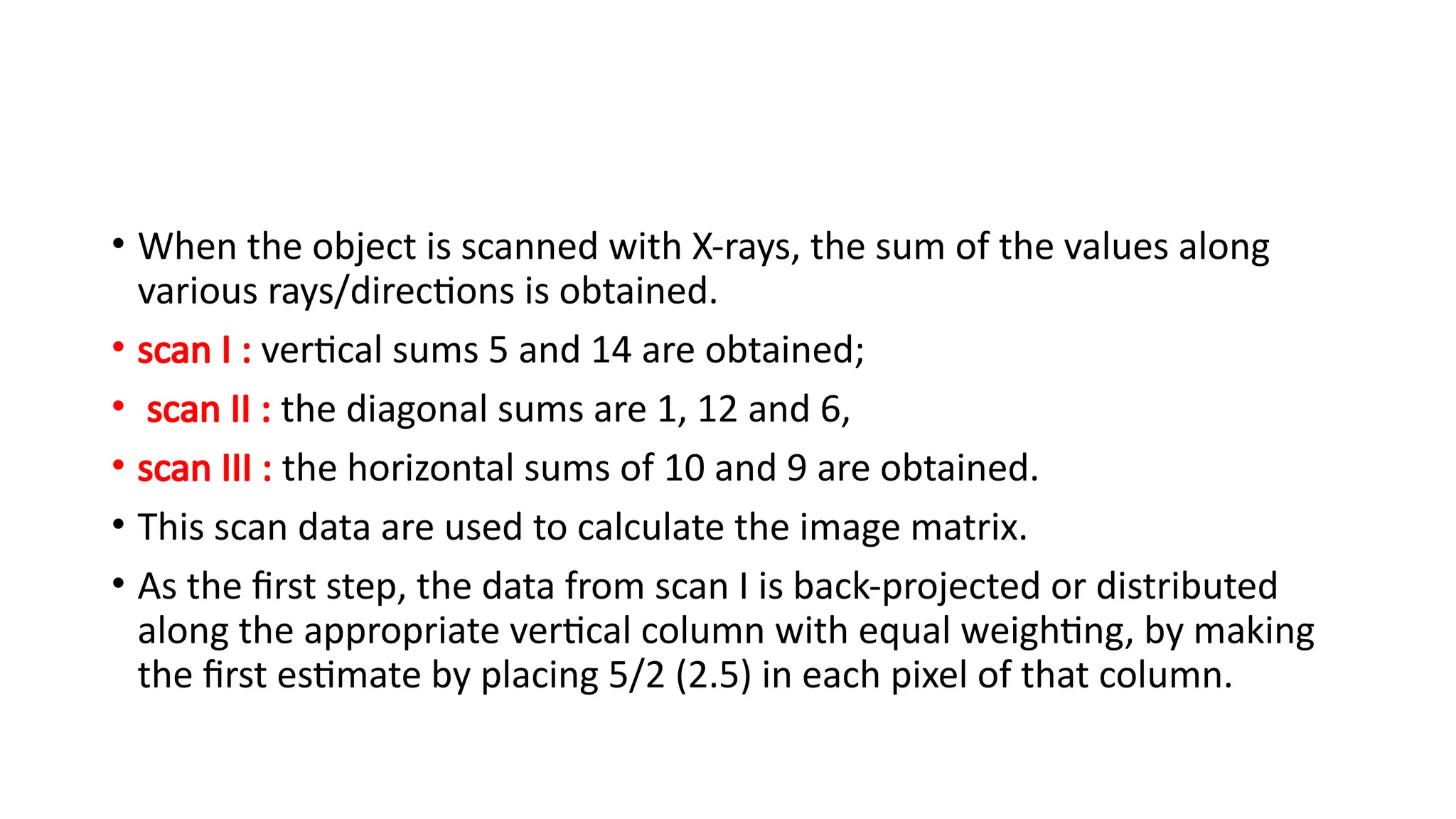
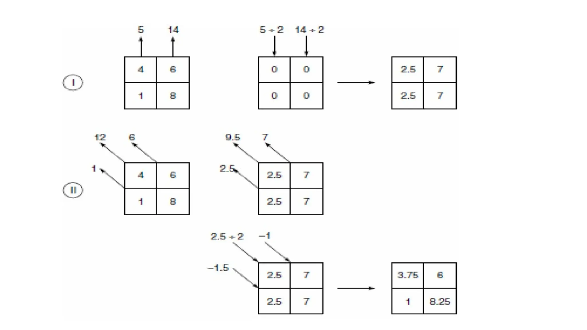
• When theobject is scanned with X-rays, the sum of the values along
various rays/directions is obtained.
• scan I : vertical sums 5 and 14 are obtained;
• scan II : the diagonal sums are 1, 12 and 6,
• scan III : the horizontal sums of 10 and 9 are obtained.
• This scan data are used to calculate the image matrix.
• As the first step, the data from scan I is back-projected or distributed
along the appropriate vertical column with equal weighting, by making
the first estimate by placing 5/2 (2.5) in each pixel of that column.
63.
IMAGE RECONSTRUCTION TECHNIQUES– BACK PROJECTION
METHOD
• each of the measured profiles is projected back over the image area
at the same angle from which it was taken.
• This technique produces ‘starred’ images and blurring, which makes it
totally unsuitable for providing pictures of adequate clarity for
medical diagnosis
• By adding the back projections produced by the shadow functions,
the back-projected rays are added to the reconstructed image as
artefacts
• The original circular structure is transformed into a star-shaped
display
64.
• In thismethod, each x-ray transmission path through the body is divided into
equally spaced elements, and each element is assumed to contribute equally
to the total attenuation along the x-ray path.
• By summing the attenuation for each element over all x-ray paths that
intersect the element at different angular orientations, a final summed
attenuation coefficient is determined for each element.
• When this coefficient is combined with the summed coefficients for all other
elements in the anatomic section scanned by the x-ray beam, a composite
image of attenuation coefficients is obtained.
• Although the simple back projection approach to reconstruction algorithms
is straightforward, it produces blurred images of sharp features in the object.
65.
FILTERED BACK PROJECTIONMETHOD
• This technique employs a spatial filter to remove the blurring artifacts.
• This is achieved by convolving the shadow function with a filter so that each
point in the projection has a negative value instead of 0, at every point other than
its proper place in the projection.
• The resulting profiles are then back-projected and added.
• Thus, the negative portion of each shadow function cancels out image artifacts
that would otherwise be caused by other functions.
• Mathematically, the method of fast Fourier transform offers a powerful tool in
making the required computations and special purpose high speed computers are
now available to meet this requirement.
• The use of this method enables pictures to be reconstructed within a few
seconds.
66.
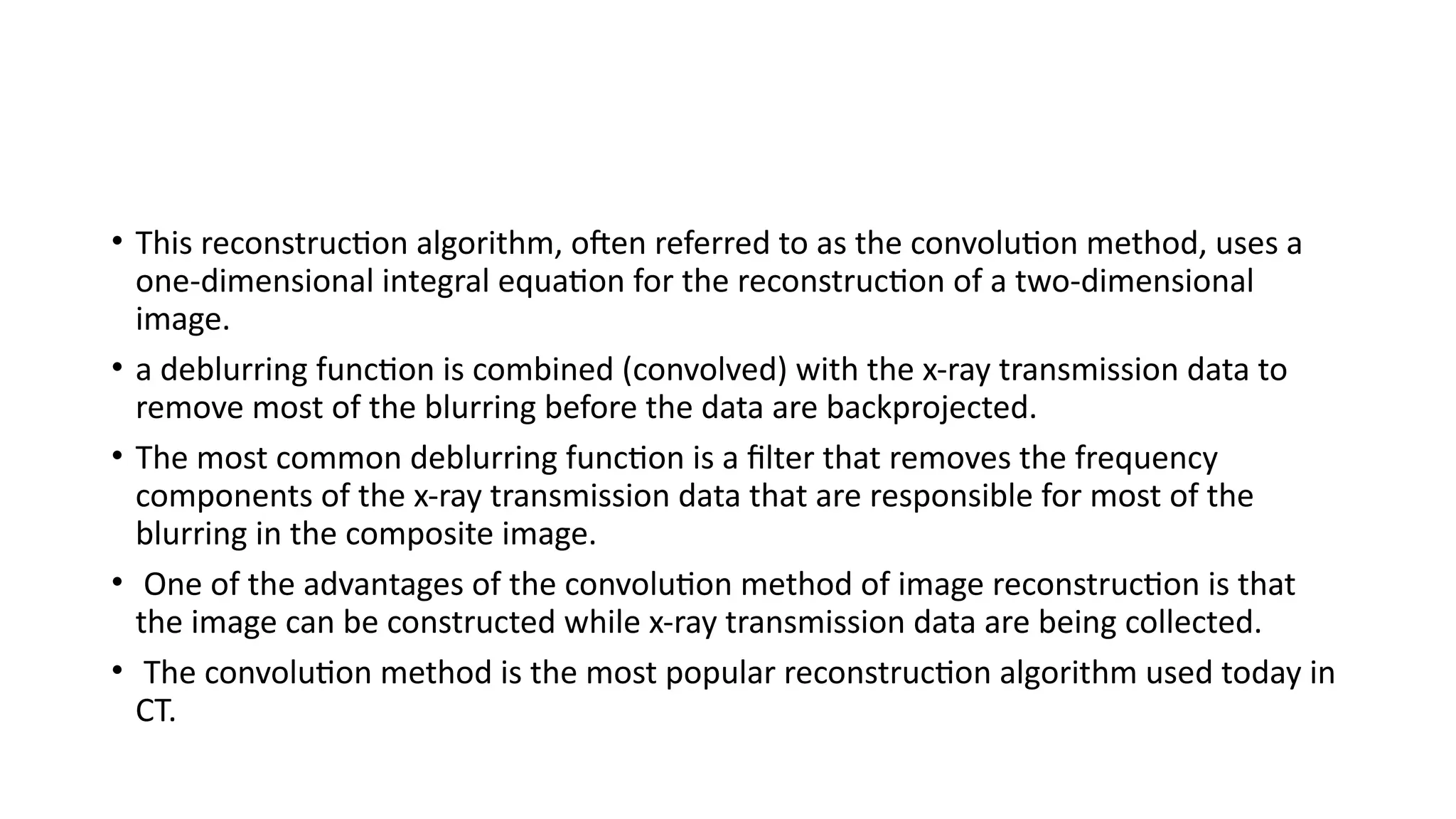
• This reconstructionalgorithm, often referred to as the convolution method, uses a
one-dimensional integral equation for the reconstruction of a two-dimensional
image.
• a deblurring function is combined (convolved) with the x-ray transmission data to
remove most of the blurring before the data are backprojected.
• The most common deblurring function is a filter that removes the frequency
components of the x-ray transmission data that are responsible for most of the
blurring in the composite image.
• One of the advantages of the convolution method of image reconstruction is that
the image can be constructed while x-ray transmission data are being collected.
• The convolution method is the most popular reconstruction algorithm used today in
CT.
67.
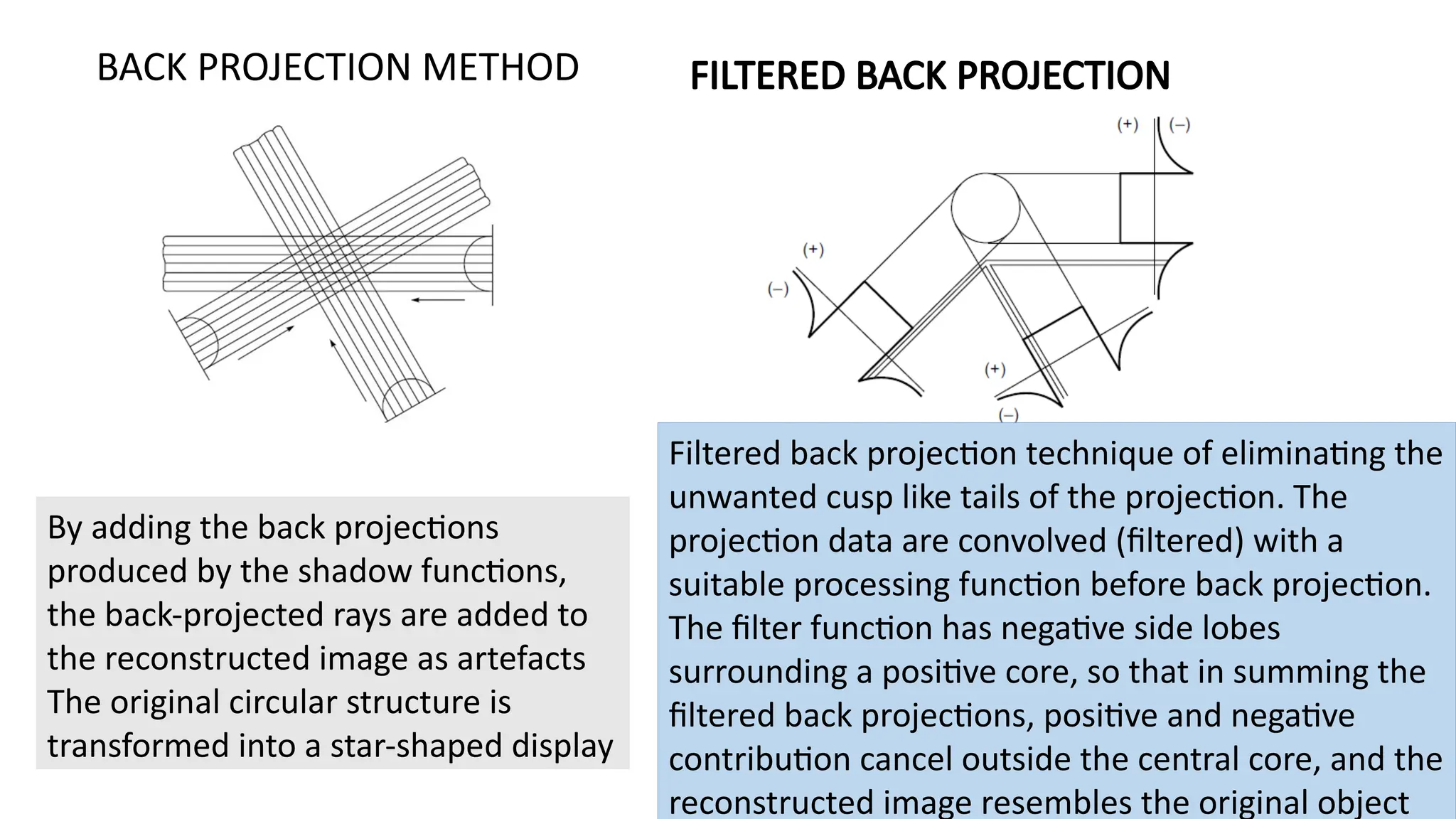
By adding theback projections
produced by the shadow functions,
the back-projected rays are added to
the reconstructed image as artefacts
The original circular structure is
transformed into a star-shaped display
BACK PROJECTION METHOD FILTERED BACK PROJECTION
Filtered back projection technique of eliminating the
unwanted cusp like tails of the projection. The
projection data are convolved (filtered) with a
suitable processing function before back projection.
The filter function has negative side lobes
surrounding a positive core, so that in summing the
filtered back projections, positive and negative
contribution cancel outside the central core, and the
reconstructed image resembles the original object