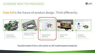
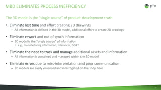
MODEL-BASED
DEFINITION WITH
CREO
2
Design for
Connectivity
Model Based
Definition
Design for Additive
ManufacturingProductivity
Improvements
LEVERAGE NEW TECHNOLOGIES
Creo 4.0 is the future of product design. Think differently.
Augmented
Reality
Transformation from a 2D centric to 3D model-based enterprise
3
LEVERAGE NEW TECHNOLOGIES
Model Based Definition
of products from best-in-class
manufacturers
achieve revenue, cost, launch and
quality targets using model based
engineering
- Aberdeen
84%
4
PAPER BASED DEFINITION
TRADITIONAL PROCESSES ARE BASED ON 2D DRAWINGS
• 1
5
2D Drawings are the accepted standard for communicating product information
• 2D drawings are engrained within the PDP
– The 2D drawing reflects achievement and point of completion
• 2D Drawings serves as the source content for quoting and manufacturing
– Utilized by procurement, contracts, quality, etc.
• 2D prints are reviewed and marked up
– 2D drawings define all aspects of the finished product
• e.g., critical dimensions, tolerances, requirements
• 2D drawings serve as the “Legal” entity
– The complete description of what is to be delivered
– Represents the "master" for quoting purposes and inspection
Slow process to change the mind-set and move to MBD
MBD IS A PROCESS CHANGE, EXPECT OBJECTIONS
6
Inefficiencies are the direct result of 2D drawing based processes
• 2D drawings are tedious and time-consuming to create and update
– Redundant, time-consuming process to create 3D geometry AND 2D drawings
• 2D drawings are frequently out of synch with the 3D Model
– Additional information is frequently added to the 2D drawing
• e.g., manufacturing information, tolerances, GD&T
• 2D drawings are additional assets to be tracked and managed
– Additional effort to manage model and associated drawings
• 2D drawings are difficult to visualize and understand
– Limited ability to interrogate and understand 2D information
TRADITIONAL PROCESS ARE PLAGUED WITH INEFFICIENCY
7
MODEL BASED ENTERPRISE
(MBE)
A.K.A. MBD (MODEL BASED DEFINITION)
• 2
8
3D modeling has replaced 2D design and is now the design methodology of choice
• 3D CAD models capture the complete digital product definition
– e.g., geometry, dimensions, tolerances, GD&T, attributes, annotations
All data is captured within the 3D model,. Why spend additional time a effort to recreate
this information on a 2D drawing?
THERE’S A BETTER WAY,.. (3D) MODEL BASED DEFINITION
Geometric Dimensioning and
Tolerancing (GD&T)
9
GD&T ADVISOR EXTENSION
EXTENDED SUPPORT FOR MBD
• 3
10
• Struggle to adopt and comply with MBD standards
– Struggle to learn and maintain knowledge of latest GD&T principles and standards
• Lost productivity and efficiency
– Lost time debating the “proper” application of GD&T
– Multiple GD&T review cycles and rework
Note: The untrained user believes there are multiple interpretations of GD&T
• Increased manufacturing cost
– Improper application of GD&T resulting in errors and misinterpretation
Note: When properly applied GD&T provides larger tolerances to
reduce part-manufacturing cost
• Unnecessary expense
– Tolerance errors lead to scrap, rework, changes, confusion and downtime
CREO GD&T ADVISOR – WHY DO WE NEED IT?
When applied incorrectly GD&T can cause inefficiencies that exceed the benefits
11
Engineers want to…
• Simplify and speed the creation of semantically correct, standards compliant GD&T
• Create and validate GD&T semantics using expert recommendations and tool tips
• Access and apply interactive GD&T help content to understand GD&T concepts
Companies want to…
• Eliminate barriers for successful MBD implementations
• Gain the benefits of GD&T to support downstream activities
• Reduce errors resulting from incorrect or incomplete GD&T semantic definition
REMOVE BARRIERS TO MBD COMPLIANCE
12
• GD&T Creation
– Simplified GD&T workflow makes it easy to define semantically correct GD&T
– GD&T authoring is 4 times faster than Creo Authoring (3D Annotation)
• GD&T Validation
– GD&T Advisor prevents users from creating invalid annotation
– Mathematics-based recommendations and evaluation
• Color coding identifies where GD&T is completely, partially or not defined
• GD&T Education
– Users are able to quickly find answers and review GD&T concepts
– Integrated help content with context with sensitive user guide, tool tips and quick reference materials
• GD&T Utilization
– Intelligent, CAD-native annotations are usable in downstream processes such as drawing production, tolerance analysis, computer
aided inspection (CMM) and other activities
When properly defined, GD&T clearly communicates design intent
CREO GD&T ADVISOR EXTENSION
Simplify GD&T creation and improve MBD compliance with latest standards (ASME & ISO)
13
The 3D model is the “single source” of product development truth
• Eliminate lost time and effort creating 2D drawings
– All information is defined in the 3D model, additional effort to create 2D drawings
• Eliminate rework and out of synch information
– 3D model is the “single source” of information
• e.g., manufacturing information, tolerances, GD&T
• Eliminate the need to track and manage additional assets and information
– All information is contained and managed within the 3D model
• Eliminate errors due to miss-interpretation and poor communication
– 3D models are easily visualized and interrogated on the shop floor
MBD ELIMINATES PROCESS INEFFICIENCY
1414
VIDEO
Model Based Design
• ASME & ISO Standards
• Streamlined workflow
• Guide
• Educate
• Validate
1515
16
Reduce engineering time and effort to define GD&T
Ex: GD&T Advisor authoring is 4 times faster than using Creo authoring
• Guided GD&T creation workflow makes it fast and easy to define semantically correct GD&T
Eliminate lost engineering time debating the proper application of GD&T
Ex: GD&T Advisor does not allow the user to correct incorrect GD&T
• Untrained users believe there are multiple interpretations of GD&T
Time and travel cost to train users on GD&T application and standards
Ex: Eliminate reliance on off-site, instructor led training to support GD&T
• GD&T Advisor guides and educates the user on application of GD&T
Lower part-manufacturing cost with the proper application of GD&T
Ex: When properly applied GD&T provides larger tolerances to reduce manufacturing cost
• When applied incorrectly, GD&T increases manufacturing cost
Reduce cost and effort to support downstream deliverables
Ex: GD&T annotations are usable in downstream applications such as tolerance analysis and
computer aided inspection (no added work)
ROI DISCUSSION POINTS (GD&T ADVISOR EXTENSION)
Reduce
Cost
Increase
Sales
17
• Aerospace
– Boeing
– Pratt Whitney Rocketdyne
– Lockheed Martin
– Northrop Grumman
– British Aerospace & Engineering
• Defense
– Raytheon
– General Dynamics
– Nuclear Weapons Complex
– National Nuclear Security Administration
(NNSA)
• Heavy Equipment
– Raytheon
– General Dynamics
– Nuclear Weapons Complex
– National Nuclear Security Administration
(NNSA)
• Automotive
– Toyota Motor Company
– Rolls-Royce Corp
• High Tech
– BAE (UDLP)
PTC CUSTOMERS COMMITMENT TO MBD
Note: Although old information, the customer data reflects the industries that are leading the MBD effort
ASME Y14.41 Committee
formed in 1998
Creo GD&T 5

Creo GD&T 5

  • 1.
  • 2.
    2 Design for Connectivity Model Based Definition Designfor Additive ManufacturingProductivity Improvements LEVERAGE NEW TECHNOLOGIES Creo 4.0 is the future of product design. Think differently. Augmented Reality Transformation from a 2D centric to 3D model-based enterprise
  • 3.
    3 LEVERAGE NEW TECHNOLOGIES ModelBased Definition of products from best-in-class manufacturers achieve revenue, cost, launch and quality targets using model based engineering - Aberdeen 84%
  • 4.
    4 PAPER BASED DEFINITION TRADITIONALPROCESSES ARE BASED ON 2D DRAWINGS • 1
  • 5.
    5 2D Drawings arethe accepted standard for communicating product information • 2D drawings are engrained within the PDP – The 2D drawing reflects achievement and point of completion • 2D Drawings serves as the source content for quoting and manufacturing – Utilized by procurement, contracts, quality, etc. • 2D prints are reviewed and marked up – 2D drawings define all aspects of the finished product • e.g., critical dimensions, tolerances, requirements • 2D drawings serve as the “Legal” entity – The complete description of what is to be delivered – Represents the "master" for quoting purposes and inspection Slow process to change the mind-set and move to MBD MBD IS A PROCESS CHANGE, EXPECT OBJECTIONS
  • 6.
    6 Inefficiencies are thedirect result of 2D drawing based processes • 2D drawings are tedious and time-consuming to create and update – Redundant, time-consuming process to create 3D geometry AND 2D drawings • 2D drawings are frequently out of synch with the 3D Model – Additional information is frequently added to the 2D drawing • e.g., manufacturing information, tolerances, GD&T • 2D drawings are additional assets to be tracked and managed – Additional effort to manage model and associated drawings • 2D drawings are difficult to visualize and understand – Limited ability to interrogate and understand 2D information TRADITIONAL PROCESS ARE PLAGUED WITH INEFFICIENCY
  • 7.
    7 MODEL BASED ENTERPRISE (MBE) A.K.A.MBD (MODEL BASED DEFINITION) • 2
  • 8.
    8 3D modeling hasreplaced 2D design and is now the design methodology of choice • 3D CAD models capture the complete digital product definition – e.g., geometry, dimensions, tolerances, GD&T, attributes, annotations All data is captured within the 3D model,. Why spend additional time a effort to recreate this information on a 2D drawing? THERE’S A BETTER WAY,.. (3D) MODEL BASED DEFINITION Geometric Dimensioning and Tolerancing (GD&T)
  • 9.
    9 GD&T ADVISOR EXTENSION EXTENDEDSUPPORT FOR MBD • 3
  • 10.
    10 • Struggle toadopt and comply with MBD standards – Struggle to learn and maintain knowledge of latest GD&T principles and standards • Lost productivity and efficiency – Lost time debating the “proper” application of GD&T – Multiple GD&T review cycles and rework Note: The untrained user believes there are multiple interpretations of GD&T • Increased manufacturing cost – Improper application of GD&T resulting in errors and misinterpretation Note: When properly applied GD&T provides larger tolerances to reduce part-manufacturing cost • Unnecessary expense – Tolerance errors lead to scrap, rework, changes, confusion and downtime CREO GD&T ADVISOR – WHY DO WE NEED IT? When applied incorrectly GD&T can cause inefficiencies that exceed the benefits
  • 11.
    11 Engineers want to… •Simplify and speed the creation of semantically correct, standards compliant GD&T • Create and validate GD&T semantics using expert recommendations and tool tips • Access and apply interactive GD&T help content to understand GD&T concepts Companies want to… • Eliminate barriers for successful MBD implementations • Gain the benefits of GD&T to support downstream activities • Reduce errors resulting from incorrect or incomplete GD&T semantic definition REMOVE BARRIERS TO MBD COMPLIANCE
  • 12.
    12 • GD&T Creation –Simplified GD&T workflow makes it easy to define semantically correct GD&T – GD&T authoring is 4 times faster than Creo Authoring (3D Annotation) • GD&T Validation – GD&T Advisor prevents users from creating invalid annotation – Mathematics-based recommendations and evaluation • Color coding identifies where GD&T is completely, partially or not defined • GD&T Education – Users are able to quickly find answers and review GD&T concepts – Integrated help content with context with sensitive user guide, tool tips and quick reference materials • GD&T Utilization – Intelligent, CAD-native annotations are usable in downstream processes such as drawing production, tolerance analysis, computer aided inspection (CMM) and other activities When properly defined, GD&T clearly communicates design intent CREO GD&T ADVISOR EXTENSION Simplify GD&T creation and improve MBD compliance with latest standards (ASME & ISO)
  • 13.
    13 The 3D modelis the “single source” of product development truth • Eliminate lost time and effort creating 2D drawings – All information is defined in the 3D model, additional effort to create 2D drawings • Eliminate rework and out of synch information – 3D model is the “single source” of information • e.g., manufacturing information, tolerances, GD&T • Eliminate the need to track and manage additional assets and information – All information is contained and managed within the 3D model • Eliminate errors due to miss-interpretation and poor communication – 3D models are easily visualized and interrogated on the shop floor MBD ELIMINATES PROCESS INEFFICIENCY
  • 14.
    1414 VIDEO Model Based Design •ASME & ISO Standards • Streamlined workflow • Guide • Educate • Validate
  • 15.
  • 16.
    16 Reduce engineering timeand effort to define GD&T Ex: GD&T Advisor authoring is 4 times faster than using Creo authoring • Guided GD&T creation workflow makes it fast and easy to define semantically correct GD&T Eliminate lost engineering time debating the proper application of GD&T Ex: GD&T Advisor does not allow the user to correct incorrect GD&T • Untrained users believe there are multiple interpretations of GD&T Time and travel cost to train users on GD&T application and standards Ex: Eliminate reliance on off-site, instructor led training to support GD&T • GD&T Advisor guides and educates the user on application of GD&T Lower part-manufacturing cost with the proper application of GD&T Ex: When properly applied GD&T provides larger tolerances to reduce manufacturing cost • When applied incorrectly, GD&T increases manufacturing cost Reduce cost and effort to support downstream deliverables Ex: GD&T annotations are usable in downstream applications such as tolerance analysis and computer aided inspection (no added work) ROI DISCUSSION POINTS (GD&T ADVISOR EXTENSION) Reduce Cost Increase Sales
  • 17.
    17 • Aerospace – Boeing –Pratt Whitney Rocketdyne – Lockheed Martin – Northrop Grumman – British Aerospace & Engineering • Defense – Raytheon – General Dynamics – Nuclear Weapons Complex – National Nuclear Security Administration (NNSA) • Heavy Equipment – Raytheon – General Dynamics – Nuclear Weapons Complex – National Nuclear Security Administration (NNSA) • Automotive – Toyota Motor Company – Rolls-Royce Corp • High Tech – BAE (UDLP) PTC CUSTOMERS COMMITMENT TO MBD Note: Although old information, the customer data reflects the industries that are leading the MBD effort ASME Y14.41 Committee formed in 1998

Editor's Notes

  • #3 Creo MBD enables transformation from a 2D centric process to a 3D model based enterprise
  • #4 Although not widely used across all industries,.. Studies have shown that 84% of products,… 2D centric business practice often result in incorrect, or misinterpretation of 2D drawings, which leads to higher scrap and product failures. Outside of engineering, people deal with incomplete or inconsistent information and waste valuable time and effort in tracking this down. Model Based Definition, or MBD, enables you to eliminate these issues and Creo 4 we have added a lot of great functionality to make implementing MBD easier. Streamlined workflows, stepping users though the process of applying the appropriate PMI information to the 3D model Support for ASME and ISO standards. Working with our partners at Sigmetrix we are offering a new GD&T Advisor extension, that will: Guide the you through the process of applying GD&T on the model Educate the you on the correct use of GD&T for the appropriate geometry Validate that your GD&T is semantically correct and conforms to the appropriate standards. And even Validate that your model is fully geometrically constrained, reducing the risk of miss interpretation or miss understanding. ____________________ EXAMPLE: TE Connectivity has done a number of MBD pilots where they saw some significant benefit from reusing the model in downstream processes. In October, they presented at an MBE conference in Colorado and talked about these two benefit areas: MBD helped them to avoid recreation of data when performing First Article Inspection (FAI) which resulted in 60% savings in the time to perform First Article Inspection. They also expect significant savings in Quality Inspection for Production parts (not just First Article), but did not cite any numbers. This is typically where the big benefits for MBD are found. It’s not so much a productivity enhancer for the Engineering Department itself because any time saved by not creating a drawing is just spent doing the same type of activity (creating annotations) but it’s just done in the 3D model instead of in the drawing. ________________________________ NOTES: What is Model Based Enterprise (MBE) and how is it different than Model Based Definition (MBD)? MBE is the deployment of MBD deliverables throughout the entire enterprise. What is Model Based Design? Many people use this interchangeable with MBD. In some cases they are referring to systems engineering (MBSE) Creo GD&T Advisor IS A NEW SELLABLE EXTENSION VIDEO AVAILABLE: https://ptc.gosavo.com/Document/Document.aspx?id=41325012&view=
  • #5 To understand the value and positioning of Creo MBD, it is important the realize that most companies have internal processes that are based on, and require 2D drawings. Creo MBD capabilities are positioned to transform traditional 2D centric processes and move towards the idea of 3D model based definition Transforming from a 2D centric process to 3D Model Based enterprise, or Digital tapestry
  • #9 3D Model Based Enterprise or Model Based Definition provides a better way,.. If you think about where companies are at today,. 3D modeling has replaced 2D design and the methodology of choice. The 3D model captures the complete digital product definition All information is captured within the 3D model,. So the question is “why are we spending additional time and effort to perform redundant work creating the 2D drawing This is the concept behind Model Based Definition In Creo we have new capabilities to improve Model Based Definition by making it much easier to create GD&T The new GD&T Advisor Extension provides additional capabilities to support MBD and the correct application of GD&T … Without GD&T Advisor individuals and companies can struggle
  • #11 To understand the need for GD&T Advisor Extension it is important to understand that companies struggle to adopt and comply with MBD standards GD&T principles and standards are continually changing requiring users to maintain a constant knowledge of the latest information The reality is that most users are not experts and seem to think there are multiple interpretations of GD&T This results in lost productivity and time debating, reworking and reviewing GD&T When applied correctly, GD&T can lower manufacturing cost by providing larger tolerances to reduce part-manufacturing When applied incorrectly, GD&T can increase manufacturing cost and lead to additional expenses due to scrap, rework , changes and confusion GD&T is used by about one-half of the world's manufacturers because it does have clear rules and is quality-oriented.  http://www.qualitymag.com/articles/84387-training-trends-nine-myths-about-geometric-dimensioning-and-tolerancing 4x faster than using Creo authoring tools
  • #12 Semantic – relating to the meaning (ex. Hole recognition) Discuss what engineers want,.. Confidently define semantically correct, standards compliant GD&T Engineers want to… Rapidly define GD&T Confidently apply GD&T using Mathematics-based recommendations and evaluation prevents unnecessary use Confidently create standards compliant GD&T Reduce errors that result from incorrect or incomplete GD&T Companies want to… Reduce errors that result from incorrect or incomplete GD&T semantic definition Eliminate barriers for successful MBD implementations
  • #13 When properly defined, GD&T clearly communicate design intent…
  • #15 Creo sees a huge investment, enabling customers to undertake this journey, And with it we are closing gaps in ASME and ISO standards. We are streamlining the workflows, stepping users though the process of applying the appropriate PMI information to the 3D model - enabling companies to capture all the required, rich, intelligent information, directly in the 3D model. Working with our partners at Sigmetrix we are going to be offering a new GD&T Advisor extension, That will: Guide the user through the process of applying GD&T on the model, significantly reducing effort and improving productivity Educate the users on the correct use of GD&T for the appropriate geometry Validate that your GD&T is semantically correct and conforms to the appropriate standards And even Validate that your model is fully geometrically constrained, reducing the risk of miss interpretation or miss understanding. Creo 4.0 stands out, in that it’s not just providing solutions for applying dimensions to a 3D model versus a 2D drawing, but a completely new set of tools to Guide, Educate and Validate your models, capturing intelligence in the design to remove downstream problems.