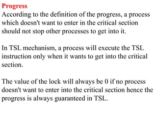
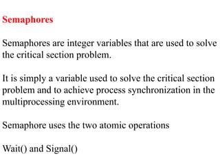
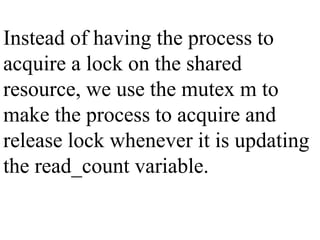
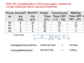
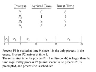
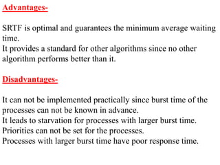
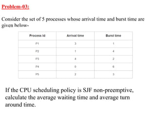
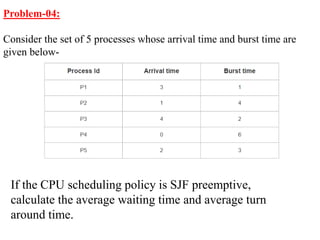
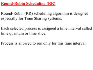
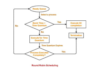
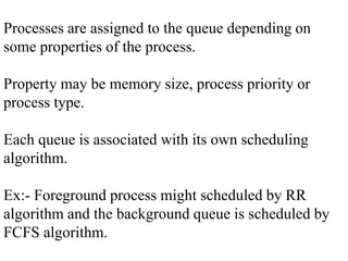
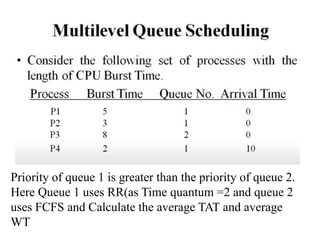
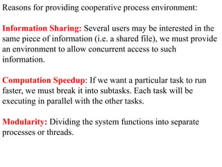
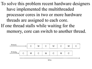
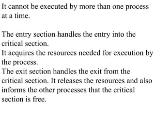
The document discusses CPU scheduling, which allows one process to use CPU resources while others wait, detailing various types such as preemptive and non-preemptive scheduling. It explains how processes alternate between CPU bursts and I/O waits, and outlines algorithms like First Come First Serve (FCFS), Shortest Job First (SJF), and Round Robin (RR), along with their advantages and disadvantages. Additionally, it covers inter-process communication mechanisms that enable processes to share data, emphasizing the importance of synchronization and message passing.
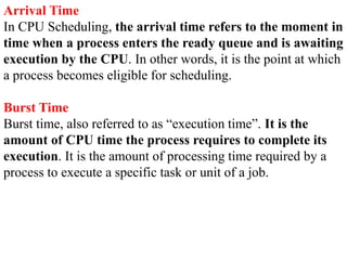
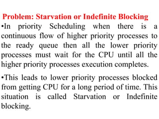
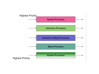
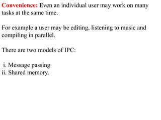
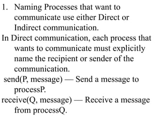
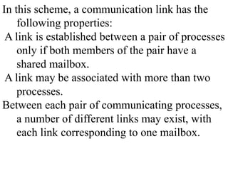

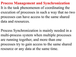
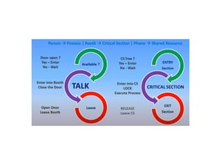

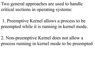
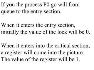
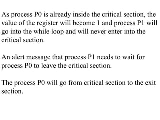
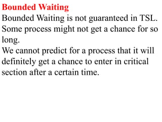
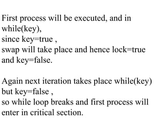
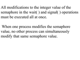
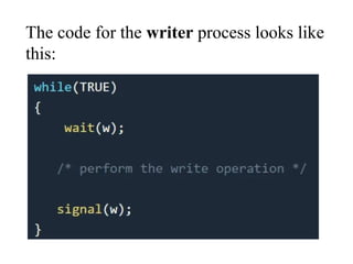
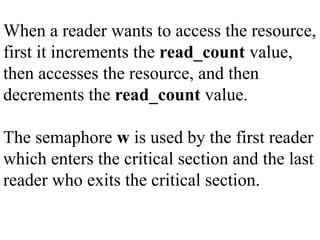
![The processes are numbered P0 and P1.
Peterson’s solution requires the two processes to
share two data items: int turn; boolean flag[2];
The variable turn indicates whose turn it is to
enter its critical section.
At any point of time the turn value will be either
0 or 1 but not both.](https://image.slidesharecdn.com/cpuschedulingunit-2-240506161514-fc9e7848/85/CPU-SCHEDULING-IN-OPERATING-SYSTEMS-IN-DETAILED-109-320.jpg)
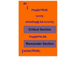
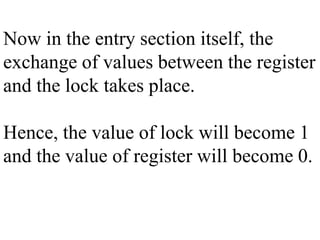
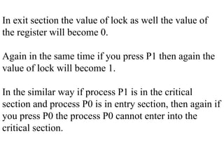
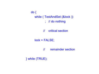
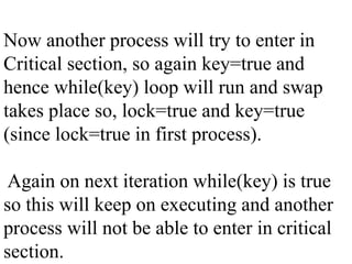
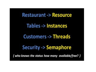
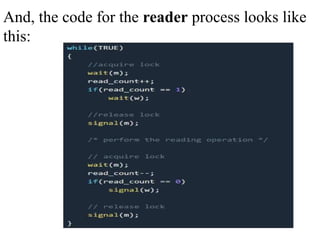
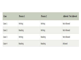
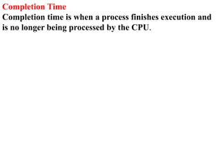
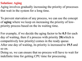
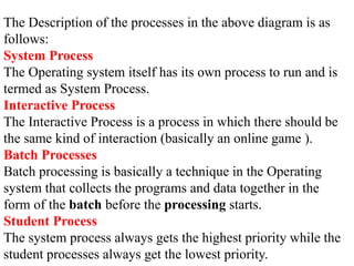
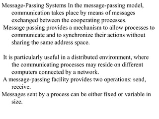
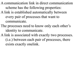
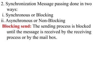
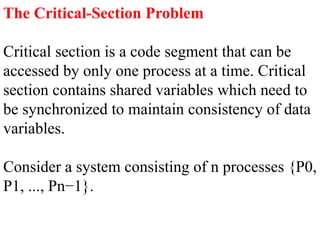
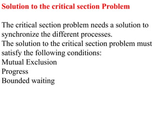
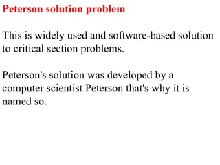
![The above shows the structure of process Pi in
Peterson's solution.
Suppose there are N processes (P1, P2, ...
PN) and as at some point of time every process
requires to enter in the Critical Section.
A FLAG[] array of size N is maintained here
which is by default false.
Whenever a process requires to enter in the
critical section, it has to set its flag as true.](https://image.slidesharecdn.com/cpuschedulingunit-2-240506161514-fc9e7848/85/CPU-SCHEDULING-IN-OPERATING-SYSTEMS-IN-DETAILED-111-320.jpg)
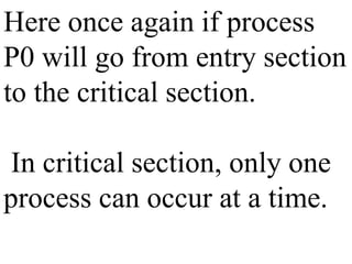
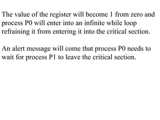
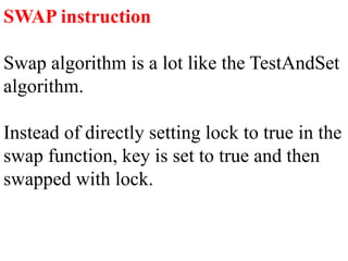
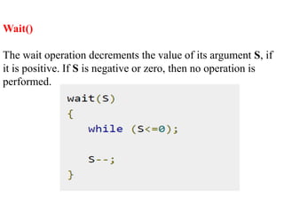
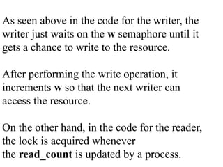
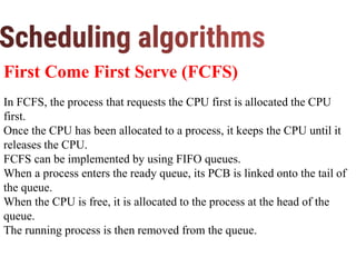
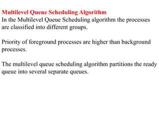
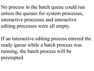
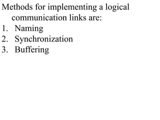
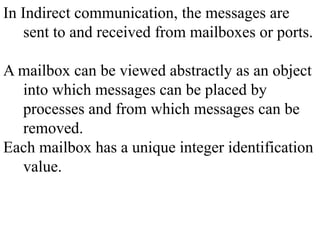
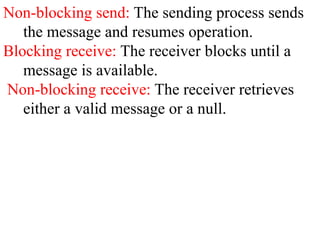
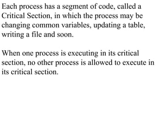
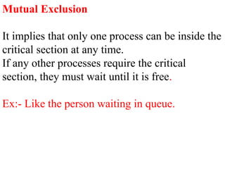
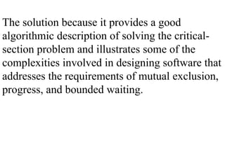
![Example: If Pi wants to enter it will
set FLAG[i]=TRUE.
Another variable is called TURN and is used to
indicate the process number that is currently
waiting to enter into the critical section.
The process that enters into the critical section
while exiting would change the TURN to
another number from the list of processes that
are ready.](https://image.slidesharecdn.com/cpuschedulingunit-2-240506161514-fc9e7848/85/CPU-SCHEDULING-IN-OPERATING-SYSTEMS-IN-DETAILED-112-320.jpg)