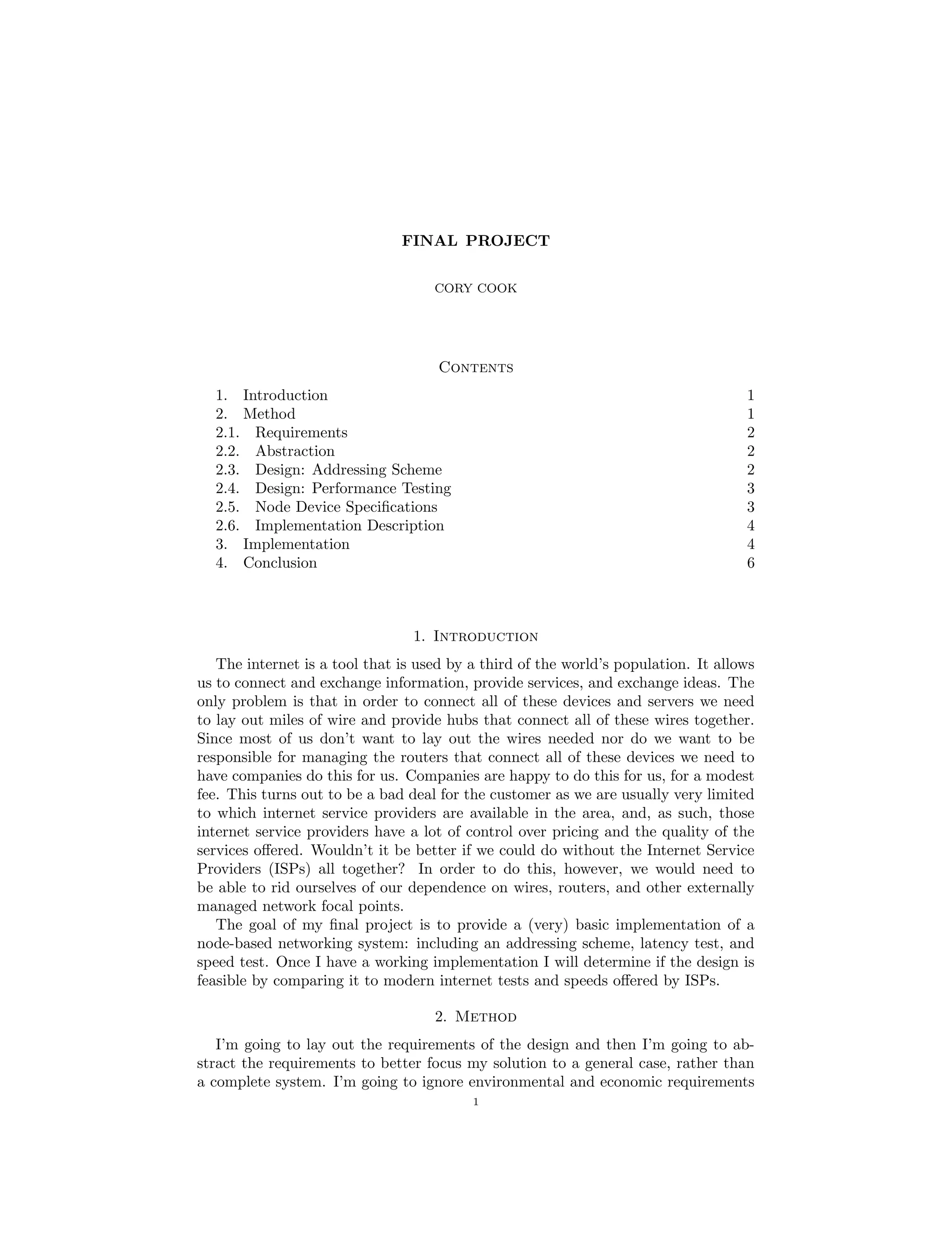
The document outlines a final project to design and implement a basic node-based networking system without internet service providers. It proposes using GPS coordinates to assign addresses and simulating data transfer between nodes to test performance. The key steps are:
1) Assign each node a unique address based on its GPS coordinates.
2) Specify node properties like transfer rate and range.
3) Simulate data transfer between random node pairs to determine latency and throughput.
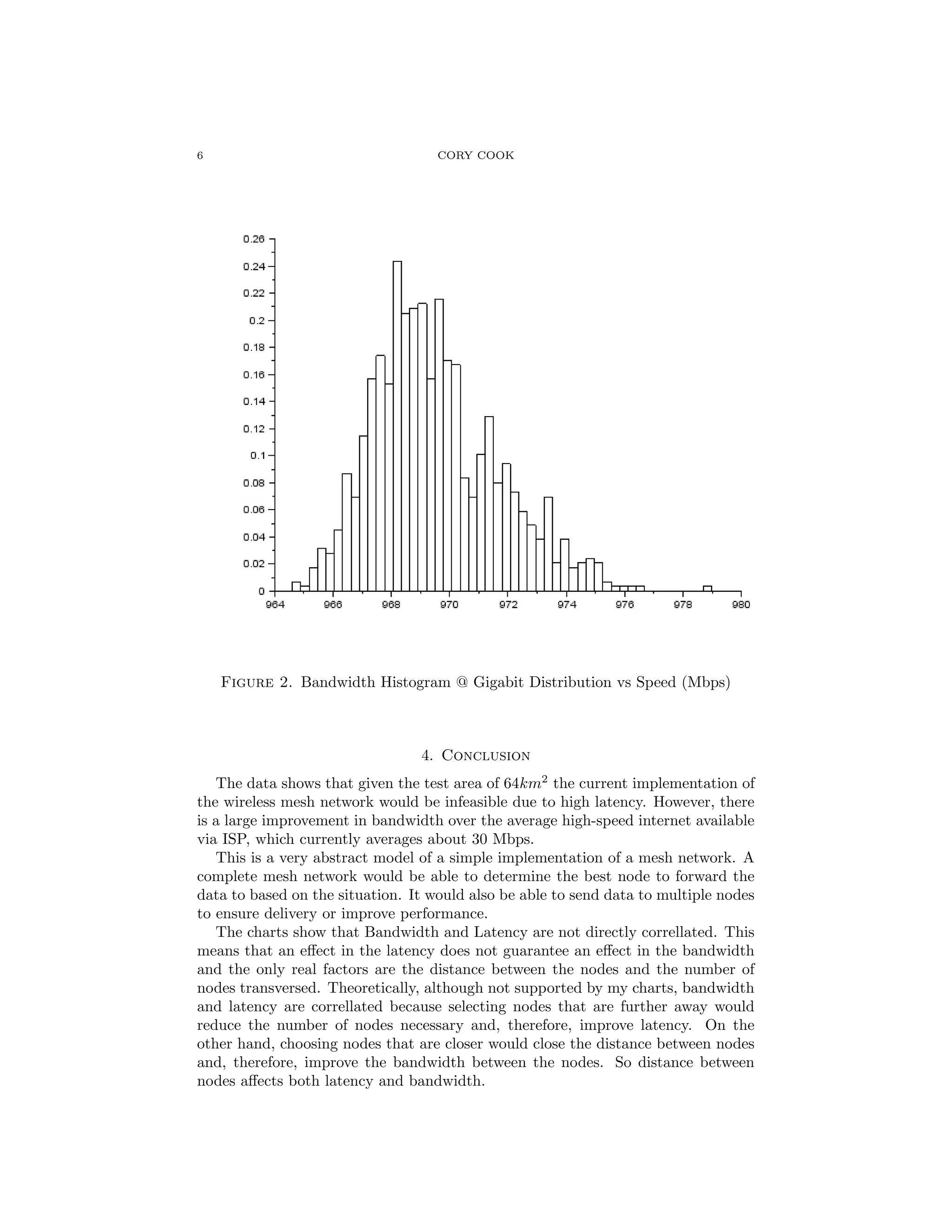
4) Analyze the results to find worst-case performance and compare to typical internet speeds.
The goal is to evaluate if a decentralized mesh network could feasibly replace traditional internet infrastructure. The document describes addressing schemes, node specifications, and the process
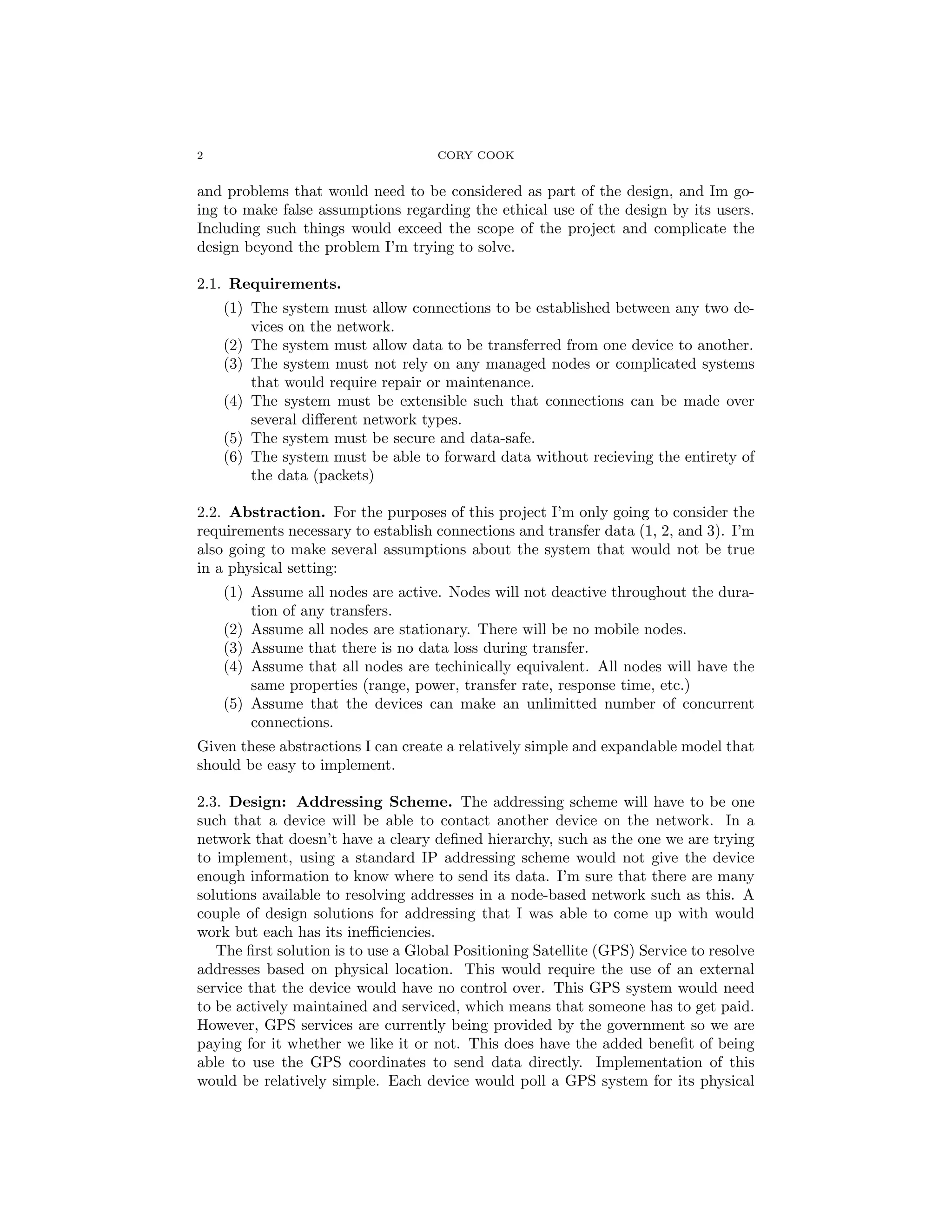
![4 CORY COOK
These specifications were selected to ensure that the entire area of the next ad-
dress over would be within optimum range for an addressing range of 8m regardless
of the current position of the object within its own address range.
2.6. Implementation Description. Each node is going to be an object with an
address and a physical position. If the current address is (a,b) and the target
address is (c,d) then the next address down the line will be determined by the
following function (one-dimension):
(1) a = c?a : a +
c − a
|c − a|
We need to determine the physical distance between the nodes such that we can
determine the signal strength and throughput. The throughput of the system is
determined by the slowest data transfer on the line so if the bandwidth of the current
node is less that that of the system throughput then set the system throughput as
the current. Add any delay or latency incurred at the current node. Repeat until
we reach the destination.
This should give us a latency and a throuput for a connection which is all we
need to determine its performance. I will repeat this method for many random
connections and record the data. Once I have the data I will determine a function
that fits the given data and use optimization technique to find the worst case
scenario for the system. Once this is determined I will compare the performance to
the performance of the average internet users’ connection and determine (roughly)
if having a massive mesh networking system would be feasible.
3. Implementation
1 grid =1000 // Sets the size of the test area
2 ps=8 // Sets the plot size (size per unit area)
3 datarate =1000
4 A = rand(grid ,grid ,2)
5 A = A*ps
6 // This is the signal degredation based on distance
7 function b=sig(t)
8 b=sqrt(-(t -40) /40)
9 endfunction
10 // Caluclates the distance between nodes
11 function d=dist(curr ,next)
12 d=sqrt (( curr (1) -next (1))^2+( curr (2)-next (2))^2)
13 endfunction
14 // Gets the coordinates of the node
15 function coords=cor(x)
16 coords =[x(1)+A(x(1) ,x(2) ,1)/ps x(2)+A(x(1),x(2) ,2)/ps]
17 endfunction
18 // Gets the next node address
19 function out=np(u, v)
20 if u==v then
21 out=u
22 else
23 out=u+((v-u)/abs(v-u))
24 end
25 endfunction
26 function [latency , throughput ]= set_val(start_pos ,end_pos ,speed)
27 latency =0](https://image.slidesharecdn.com/367f1969-793a-4eab-ac62-b6d8c09d69ef-150613174904-lva1-app6891/75/CoryCookFinalProject535-4-2048.jpg)
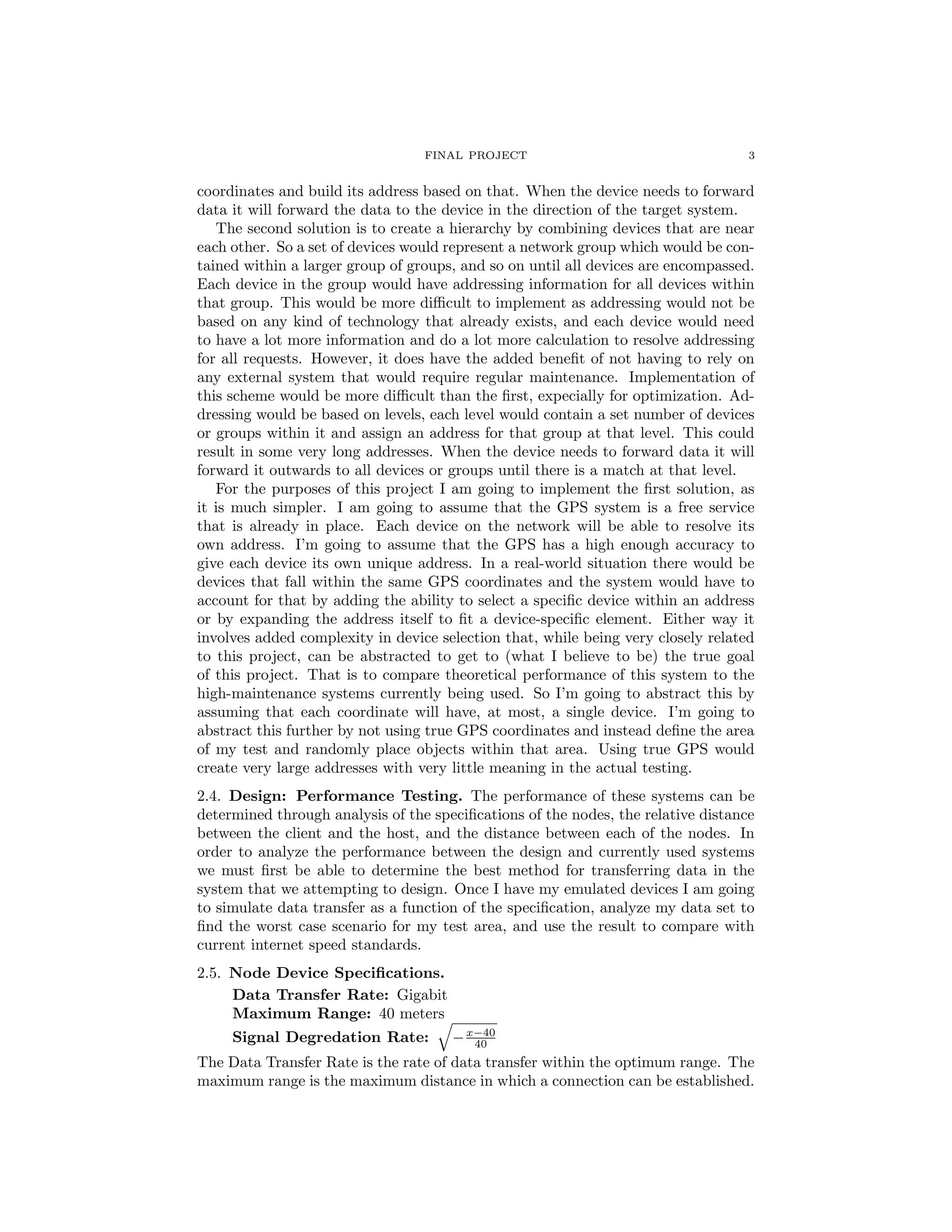
![FINAL PROJECT 5
Figure 1. Latency Histogram Distribution vs. Time (ms)
28 throughput=speed
29 current_pos = start_pos
30 while or(current_pos ~= end_pos)
31 next_pos (1 ,1)=np( current_pos (1), end_pos (1))
32 next_pos (1 ,2)=np( current_pos (2), end_pos (2))
33 latency=latency +1
34 val=sig(dist(cor(current_pos), cor(next_pos)))*datarate
35 if val <throughput then
36 throughput=val
37 end
38 current_pos = next_pos
39 end
40 endfunction
41 for i=1:1000
42 start_pos =[ ceil(grid*rand ()) ceil(grid*rand ())]
43 end_pos =[ ceil(grid*rand ()) ceil(grid*rand ())]
44 startp(i,:)=start_pos
45 endp(i,:)=end_pos
46 [lat(i), band(i)] = set_val(start_pos ,end_pos ,datarate)
47 end
Listing 1. Mesh Network Implementation](https://image.slidesharecdn.com/367f1969-793a-4eab-ac62-b6d8c09d69ef-150613174904-lva1-app6891/75/CoryCookFinalProject535-5-2048.jpg)