SlideShare a Scribd company logo
1 of 83
Download to read offline
Stone arch bridges
A strong & cost effective technology for rural roads
A practical manual for Local Governments
Kasese District Local Government
1
Foreword
This manual was developed based on the
experience of the Belgian Technical
Cooperation (BTC) supported Kasese District
Poverty Reduction Programme (KDPRP) in
Western Uganda, during the period 2009-
2013. The programme piloted stone arch
culverts and bridges in rural areas, where low
labour costs and high cost of industrial
building materials favour this technology. The
construction of stone arch bridges in Uganda,
Tanzania & Rwanda has demonstrated its
overall feasibility in East Africa.
How to use this manual
The purpose of this manual is to provide
supervisors of stone arch bridge works with
an easy step by step guide. The stepwise
approach ensures adherence to quality
requirements and construction methodology
The main target audience of this manual is
the road works supervisors and engineers
employed by District Local Governments in
East Africa. However, the manual remains
relevant in the context of many other
developing countries.
Acknowledgements
Many people and institutions contributed to
this manual: the KDPRP steering committee,
Local Authorities at District and Sub County
levels, the District Executive Committee and
the Chief Administrative Officer, William
Kanyesigye. Special thanks goes to Paul
Dequeker, Belgian architect, for having
shared his broad experience in Congo with
us. The manual was written by Eng. Sophie
Grigoletto and Steven Hollevoet. The draft
was reviewed by the Kasese District Works
department, Alphonse Katswamba , Dave
Renno, Ruediger Behrens (GIZ) and Neil
Noble of Practical Action. Neil also produced
some of the technical drawings.
Jonas Geeroms edited some diagrams.
BTC Uganda and the BTC junior programme
made this work possible.
Table of contents
1. Chapter 1: Introduction to stone arch bridges ..............................2
1.1Background and justification.......................................................2
1.2The stone arch bridge technology...............................................3
1.3Advantages & limitations. ...........................................................5
1.4Stone arch bridges: implications of labour-based technology....7
2. Chapter Two: Design of stone arch bridges...................................8
2.1Quick scan – site assessment ......................................................8
2.2Planning and stakeholders involved............................................9
2.3Design..........................................................................................9
2.4Site conditions and arch types. ...................................................9
2.5Calculation of the flow and the bridge span .............................11
2.6Bridge dimensions .....................................................................12
Roman arch bridge .....................................................................12
Segmental arch bridge................................................................13
Culverts.......................................................................................14
2.7Calculation of the quantities of materials.................................15
2.8Drawings....................................................................................15
3. Chapter Three: Construction of stone arch bridges ....................16
3.1Principle: wedging - only compression forces...........................16
3.2Steps of construction process ...................................................17
3.3Selection of construction materials...........................................33
3.4Implementation modalities and site management...................35
3.5Common construction mistakes................................................38
3.6Training of masons ....................................................................40
3.7Promoting the technology.........................................................40
4. References and further reading...................................................41
5. Table of Annexes..........................................................................42
Cost estimates, drawings, Memorandum of Understanding
Technical Specifications, Assessment Checklist.
This document has been produced in printed from, DVD, and as an online version
of BTC http://intranet.btcctb.org and Practical Action http://practicalaction.org
2013
2
1. Chapter One: Introduction to stone arch bridges
1.1 Background and justification.
Stone arch bridges are amongst the strongest in the world. The technology has stood the test of time.
The Romans built stone arch bridges and aqueducts with lime mortar more than twenty centuries
ago. Arches and vaults were also the determining structural design element of churches and castles
in the Middle Ages (fig 1&2). There are stone arch bridges which have survived for hundreds and even
thousands of years, and are still as strong today as when they were first constructed (see fig. 5).
Fig 1: Vaults built in churches 14
th
century
Santiago de Compostela cathedral, Spain
Fig 2: Ancient stone arches street
medieval town of San Gimignano, Italy
Picture: courtesy Wikipedia.
The main reason that western countries moved away from stone arch bridges is because of the high
labour costs involved in their construction. In industrialised countries, it is cheaper to use pre-stressed
concrete rather than employ a lot of masons and casual labourers. In the economic environment of
East Africa and the majority of developing countries, with low labour costs and high costs of industrial
building materials, stone arch bridges provide a more affordable and practical option.
Technology choice Adapted to following economic context Typical example
Reinforced/
pre-stressed concrete bridges
• High labour costs
• Low cost of industrial building materials
• Industrialised countries.
• Highway contractors.
Stone arch bridges • Low labour costs
• High cost of industrial building materials
• Rural areas in developing countries.
• Community road projects
Each financial year, districts and lower local governments are faced with funding constraints while
the challenges in the rural transport sector are overwhelming. The limited available road funds are
spent on costly public procurement of a few structures and road repair while most of the grassroots
requests remain without support. Rural roads are often designed with an insufficient number of
culverts due to the high cost of concrete culverts. It causes inadequate drainage and premature
erosion, leading to increased maintenance costs of the road network. On the other hand, due to
budget constraints, timber bridges are constructed with a limited lifespan of 4-10 years and the
need for constant repairs. The adoption of stone arch bridges enables districts and lower local
governments to improve the access to social services and markets of more village communities at
70% lower investment costs. Stone arch bridges offer a low-cost but strong technology that is
appropriate for rural areas in developing countries.
3
Fig 3: Eroded road due to insufficient
drainage capacity of the culverts
Fig 4: Timber log bridges have limited span
(10 to 12m) and lifespan (4 to 10 years).
1.2 The stone arch bridge technology
Arch bridges are among the oldest types of bridges.
Dating back to ancient China, Rome and Persia, this
bridge structure has been in use for thousands of
years. Because of the strength, many ancient bridges
can still be seen today in cities of Europe and Asia. The
Romans were the first to fully realize the potential of
arches for bridge construction and built many
spectacular arch bridges, over 2000 years ago (fig 5)!
For local masons first exposed to arches, the concept
remains abstract and shaky. The structure is
completely unstable until the two spans meet in the
middle and the arch is closed. From a layman’s
perspective, it is hard to see how a bridge merely built
with stones will support heavy traffic. However, the
structure is ultimately rendered robust by the
wedging principle of the stones that distribute the
load as compression along the whole arch to the
foundations. Tensile stresses are omitted.
Fig 5: Roman stone arch bridge built over the Tagus
River at Alcántara, Spain between 104 and 106.AD
(Total length: 194m, longest span: 28m)
Picture: courtesy Wikipedia.
While there is quite some variety in arch bridge construction, the basic structure does not change.
They can be architecturally different; but they are structurally the same. The simplest shape of an
arch bridge is a semicircular design with abutments on each end. Its structure distributes
compression through its entire form and diverts weight onto its two abutments. Tensional force in
arch bridges, on the other hand is virtually negligible. Arch bridges do not need additional supports
of reinforced steel. They are particularly suitable for building in stone because each of the elements
in the arch will be under compression (fig 6).
4
Fig 6: Load distribution in a semi-circular arch: the
weight on top of the arch is diverted to the abutments
through the arch. The arch is almost entirely under
compression without any tensile stresses.
Single stone arch bridges can cover
spans up to 20 meters. For larger
spans, steel and pre-stressed
concrete is required. Steel arches
typically span between 50 and 250
meters, but West Virginia's New
River Gorge Bridge built in 1977 has
an impressive span of 518 meters
(fig 7).
Fig 7: New River Gorge Bridge, a steel arch bridge West Virginia, USA
Picture courtesy Wikipedia.
The construction of arch bridges all follow the same basic principle (fig 8), which is simple but
requires some experience and training to ensure strong and long lasting structures. Stone arches
are built over a temporary wooden formwork which holds the masonry in place during construction.
The temporary form is needed since the structure is not stable until the arch is closed. The
paragraph 3.2 gives more details about the different steps of the construction
Temporary wooden formwork which is
removed once the arch is closed.
Arch with stones placed according to
the radius of the semi circle.
Abutment with stones laid flat with a
good bond
Fig 8: Basic elements of arch bridge construction. The arch is constructed symmetrically over a temporary
formwork. Note that the arrangement of the stones differs entirely between the arch and the abutment. Stones of
the abutments are placed in a flat and horizontal position while the ones forming the arch follow the radius of the
circle. This arrangement is the key principle for the stability of the bridge.
5
1.3 Advantages & limitations.
When compared to concrete bridges, stone arch bridges offer several advantages.
A larger proportion of locally available resources
are used in stone bridges as they can be built with
local labour and stones. In contrast, raw materials
and machines have to be imported for the
construction of concrete bridges and specialized
technical expertise is required. Compared to
expensive aggregates, local stones are a strong,
affordable material and they are often available in
the vicinity (10-15 km) of the construction site.
There is no need for expensive steel bars,
aggregates, concrete or galvanised pipes that have
to be hauled over long distances.
Fig 9: Construction of a multiple-arch culverts with
stones found in the vicinity
As regards to the construction cost, concrete bridges require more capital and equipment (poker,
concrete mixers). The cost of additional man-days required for the construction of stone arch
bridges in rural areas is usually much lower than the higher cost of industrial materials and
equipment used in concrete bridges as the table below illustrates.
Construction
Cost in Ush
2012
Cost in US$
2012
Cost saving arch
technology
Bridge box culvert - public procurement span 4m 116,000,000 44,000
Stone arch bridge - forced account span 4 m 20,000,000 8,000 83%
Reinforced concrete bridge – public procurement span 8m 250,000,000 95,000
Stone arch bridge - forced account span 8 m 39,000,000 15,000 84%
Culvert 3 lines 75 cm diameter - public procurement 28,000,000 11,000
Triple culvert 80 cm diameter - forced account 5,900,000 3,000 79%
Examples of cost comparison stone arch/concrete bridges, rural Uganda 2012- 1 US$= 2.650 Ush.
The weight of the stone arch culverts reduces the risk of floods washing them away. The
interconnecting arch and the heavy weight also prevent the tilting and sliding exerted by the
backfilled soil mass - typical technical challenges related to concrete bridge abutments. Moreover,
stone culverts cannot be stolen and resold, unlike galvanised or concrete pipe culverts.
Compared to bridges made from tree logs, the stone arch bridges are more durable. They do not
need to be re-built every 3 to 5 years. This makes the investment and community effort more
effective, while the safety standard and traffic load capacity increase drastically.
However, concrete bridges will be the right technology choice where labour costs are high and
where large spans are involved. The maximum single span of stone bridges is usually less than 20
meters. For larger single spans, the volume of stone masonry becomes too massive and reinforced
concrete is a better option.
6
SUSTAINABILITY
CRITERIA
STRENGTHS WEAKNESSES
ECONOMICAL
• No need for expensive equipment
• Long lifetime
• Low cost
• Easy to maintain at local level
• More expensive where labour and local
stones are expensive.
TECHNICAL
• Stronger
• Adjustable to local conditions
• No traditional skills for arches, requiring
prior training of masons
SOCIAL/
POLITICAL/
CULTURAL
• Technology manageable at community
level.
• New technology requires a change of mind-
set and the sensitisation of the community
and local governments.
ENERGY
BALANCE
• Use of local materials, reduced use of
industrial materials and dependence on
long distance transportation
• Higher energy cost than timber bridges due
to use of cement but lifespan also 30 times
longer.
ECOLOGICAL
• Limited use of timber as forests are
under threat.
• Maintains the beauty of the landscape as
natural stone blends in well with the
environment.
• borrow pits for stone and sand might affect
landscape and accelerate erosion but same
applies to concrete bridges.
There are some limitations to constructing stone arch bridges. It is important to assess the local
context to make sure a stone arch bridge is the right solution. Where the cost of labour is high or
where large quantities of stones cannot be found in the vicinity, the construction cost of a stone
arch bridge could exceed the one of a concrete bridge. Another challenge is the capacity building of
local craftsmen and contractors. Where no stone masonry tradition exists, masons need to be
trained to master this technology and adhere to technical specifications.
Fig 10. Vocabulary of arch bridges
1. Wing wall
2. Head wall
3. Spring
4. Key stone
5. Ring stone
6. Abutment
7. Shoulder
7
1.4 Stone arch bridges: implications of labour-based technology.
Apart from the requirement of crossing a river, job creation is one of the objectives that this kind of
construction can meet perfectly. The beneficiary community can indeed be integrated in the
construction of stone arch bridges. Unemployment is usually high in rural areas of developing
countries. Due to the high labour input required for the construction of stone arch bridges, seasonal
employment can be increased. As the construction is simple, low-skilled labour can be used to
implement the work. Unskilled workers from the villages collect stones and sand, masons build the
bridges, and village carpenters make the simple scaffolding that is needed. It promotes
employment, focusing on people and their skills rather than machines and imported diesel.
Fig. 11: The community can be involved in the construction of a stone arch bridge.
This approach enables also the involvement of the rural communities and district councils during
the planning and execution of road works and results in a greater sense of ownership, self-reliance
and community cooperation. The execution of the works can be delegated to village road
committees. Villages can potentially access donor and government funding for road works through
the matching of local resources. This approach favours the adoption of stone arch bridge
technology by communities and also by local governments. The allocation of road funds based on
effective community contribution is a more just principle than electoral campaign considerations
based on patronage networks.
Involving the community in the construction process is usually also one of the main challenges of
the construction project. Successful bridge construction depends on a committed leadership and
whether the bridge was identified as a top community priority. Without these preconditions, it is
difficult to mobilise the community on a voluntary basis, especially where public procurement
demonstrated a wasteful use of resources in the past.
Next to the “force on account” approach, stone arch bridges can also be tendered through the
public procurement system and contracted to construction firms. Still cost advantages will be
important, as steel and concrete unit costs of conventional bridges are replaced by the much lower
unit costs for stone masonry.
8
2. Chapter Two: Design of stone arch bridges
2.1 Quick scan: assessment of the grassroots request and site
During the local government participatory planning and budgeting cycle, there are many demands
for the construction of bridges. Some requests are politically motivated; others have strong socio-
economic drivers. In the context of limited budgets, it is important to select the most economically
relevant bridges which are strongly supported by the community. A preliminary survey will give a
quick insight into the cost of the construction and the willingness of the community to contribute.
Based on this data, the number of bridges in terms of the cost and the priority sites can be
identified. Priority bridges can then be selected by the relevant local government bodies.
Fig. 12: Site assessment
The preliminary assessment should be carried with regards to:
• Existing building skills and experiences of local craftsmen.
• Demand analysis, acceptability amongst local inhabitants and community
commitment. Is the bridge really a development priority of the local community?
• Costs of labour and materials – vicinity of borrow pits for stones, sand and murram.
• Technical site characteristics:
• Hydrology (Flood, discharge, river profile, risk of erosion, etc)
• Sub-soil - test pits to assess bearing capacity
• Previous bridge and road works by the community
• Level of skills  means of local contractors and craftsmen
• Economic activities of the area – socio economic justification for the construction
as compared to mere political demands.
• Crop production: cash and food crops.
• Existing markets and trade centres
• Improved access to schools and health facilities
• Population density – number of village benefiting
• Expected future traffic
A checklist intended to help planners and technicians assess the feasibility of a proposed bridge
construction project can be found in the annex 6.
9
2.2 Planning and stakeholders involved.
Multiple stakeholders are involved in a construction project.
The benefiting community will actively participate in the construction. They are organized in a road
committee. An entrepreneur can be contracted to implement the construction, or a mason, assisted
by casual labourers from the community. Local governments at sub-county / ward and district levels
are involved at every step of the process. Each stakeholder has its responsibility to ensure the
implementation of the project. The structural analysis and drawings are prepared by the district
works department. Entrepreneurs or qualified mason are trained and contracted for the
implementation of the works. Tools and cement are provided by the district. Local building
materials like stones, sand and murram can be collected by the community, coordinated by their
road committee. They can also provide labour for the site clearance, excavation, trenching,
compacting and backfilling, under the supervision of the works department. The lower Local
Government is responsible for the mobilization of the community. The construction is monitored by
the District Works Department, assisted by the lower local government. The road committee
reports to the district in case of problems with the quality and quantity of the works provided by
the masons and/ or contractor.
A Memorandum of Understanding (see annex 4) is signed between the lower local government, the
community and the district. It gives more details about the possible responsibilities of each
stakeholder and the implementation modalities. It is an important tool for improved
communication and planning.
2.3 Design
The following recommendations aim at helping planners and technicians with the design of a stone
arch bridge on rural feeder roads.
Standard design tables were adopted as outlined in the tables of paragraph 2.6. These design
parameters are based on the work of architect Paul Dequeker in the Democratic Republic of Congo
(reading reference 14) and the design manual of the French Ministry of Works (reading reference 9).
For further strength analysis, the doctor thesis of Alix Grandjean (Lausanne 2010 - reading reference 1)
gives an excellent background.
2.4 Site conditions and arch types.
Site conditions determine the type of the arch:
• Roman arches (i.e. half circle) are the strongest and the simplest to construct. They are the
favoured option where gully or riverbanks are high enough to allow for large radiuses within the
bridge span.
• Segmental arch bridges (only a circular segment) are the necessary design option in lowlands
and flat valleys. They avoid that the bridge will stick out as a large hump and that large
quantities of murram will have to be hauled for the road approaches. Segmental bridges are
structurally less strong than roman arches.
10
Fig. 13: Recommended bridge type in function of the landscape and river crossing.
Site conditions Recommended arch type
High riverbanks  gullies
(Height of the riverbank
is larger than 1/3 of the
bridge span)
Roman arch
Flat areas
Low river banks
Valley grounds
Segmental arch
Wide rivers with rock
formations in the river
bed
Multiple roman arches
with piers on the rocks
in the river bed
Wide rivers 15 metres Segmental arch
Road drainage.
Narrow brook and gullies
 1 metre
Single arch culvert
Swamps and brooks.
Irrigation canals.
Sub soil with weak
bearing capacity.
Multiple culverts 
vented drifts
11
2.5 Calculation of the flow and the bridge span
The opening of the arch bridge should allow the river to pass through it. By examining the
riverbanks and asking local residents the highest flood water levels they have observed, the
maximum discharge of the river can be calculated. The section of the opening should be equal to
the surface of the trapezoid outlined by the highest water level (fig. 14). From there, the required
span of the bridge can be calculated, taking into account the site conditions. The opening should be
wide enough to minimize constriction of the natural channel. But it should not be too wide, as this
could encourage river deposits likely to modify the flow of the river. In addition, there is no
advantage of constructing a bridge taller than the highest flood level. Beyond that point, no water
will be evacuated unless the road is raised and the bridge span increased.
Fig. 14: Left side: river profile at highest water level. Right side: Roman stone arch bridge with an equivalent
opening. Hatched surfaces have the same area, i.e. the area of the river section at highest
water level. The radius of the required roman bridge can easily be calculated:
The construction of sufficient large bridges to allow for the discharge of floods will not be a problem
for rivers with high banks. However, in low laying valleys with small river banks, there is usually a
conceptual problem. On one hand, the areas flood and large bridge openings are required to absorb
the water flow. On the other hand, a large bridge will constitute a high hump that will be an
obstacle to traffic and require a lot of costly backfilling. A balance needs to be struck between the
two construction considerations.
Low valleys will often entirely flood during the peak of the rainy season. Under these conditions, the
road level needs to be raised considerably, which is often more expensive than a bridge structure
itself. Alternatively, the bridge can be relocated to a more suitable site or several bridges can be
built in series over existing river arms or a vented drift should be designed.
Due to their heavy weight, stone arch bridges resist well floods provided that their foundations are
protected against erosion. During the torrential floods in Kasese in May 2013, none of the arch
bridges was damaged while many other conventional structures were damaged.
12
2.6 Bridge dimensions
Roman arch bridge
The dimensions of a Roman arch bridge can be determined from the table below, as a function of
the required span (2R). The dimensions are for a maximum traffic load of 40 tons. The roman arch
bridge is the strongest design.
Fig. 15: diagram, formwork and example of a roman arch bridge
Span
(m)
Thickness
keystone
Thickness
at
30°
Radius
extrados
Thickness
abutments
Height
abutments
Min.
Depth
foundations
Masonry
volume
(incl.
foundations)
/m
Masonry
volume
(incl.
foundations)
for
3m
width
2R V v r E H h m³ m³
1 0.28 0.75 4.00 0.44 0.63 0.50 2.32 6.97
2 0.30 0.82 3.38 0.63 0.91 0.60 3.79 11.36
3 0.33 0.89 3.70 0.83 1.19 0.70 5.40 16.19
4 0.35 0.96 4.19 1.02 1.48 0.80 7.16 21.47
5 0.38 1.02 4.74 1.21 1.76 0.90 9.07 27.20
6 0.40 1.09 5.32 1.40 2.05 1.00 11.13 33.38
7 0.43 1.16 5.91 1.59 2.33 1.10 13.33 40.00
8 0.45 1.23 6.51 1.78 2.61 1.20 15.69 47.07
9 0.48 1.30 7.11 1.98 2.90 1.30 18.20 54.59
10 0.50 1.37 7.72 2.17 3.18 1.40 20.85 62.55
11 0.53 1.43 8.33 2.36 3.47 1.50 23.66 70.97
12 0.55 1.50 8.94 2.55 3.75 1.60 26.61 79.83
13 0.58 1.57 9.56 2.74 4.04 1.70 29.71 89.14
14 0.60 1.64 10.17 2.93 4.32 1.80 32.97 98.90
15 0.63 1.70 10.79 3.13 4.60 1.90 36.37 109.11
Source: Dequeker Paul, Architect
Width
For rural feeder roads, the standard width of a bridge is 3.6 meters, which allows for single lane
crossing of lorries.
Height
The roadway should be above the flood level, which can usually be determined by examining the
riverbank and asking local people the highest water level they have observed. If necessary, the
bridge must also provide an adequate clearance for boat passage.
Segmental arch bridge
It is possible to increase the span up to 20m
bridge is practical for flat valleys and larger spans.
arch. The bridge dimensions for a maximum traffic load
Fig. 16: Diagram, formwork
L (m) F R
1 0.20 0.72
2 0.40 1.45
3 0.60 2.17
4 0.80 2.90
5 1.00 3.62
6 1.20 4.35
7 1.40 5.07
8 1.60 5.80
9 1.80 6.52
10 2.00 7.25
11 2.20 7.97
12 2.40 8.70
13 2.60 9.42
14 2.80 10.15
15 3.00 10.87
16 3.20 11.60
17 3.40 12.32
18 3.60 13.05
19 3.80 13.77
20 4.00 14.50
13
increase the span up to 20m by using another arch shape.
bridge is practical for flat valleys and larger spans. The segmental arch is less strong than the roman
for a maximum traffic load of 15 tons are given in the table below.
, formwork and example of a segmental arch bridge.
V r v E H
m³/m
0.28 3.37 0.52 0.64 0.38 2.77
0.31 3.59 0.60 0.94 0.43 4.54
0.34 4.29 0.67 1.23 0.48 6.36
0.38 5.09 0.74 1.50 0.53 8.28
0.41 5.93 0.80 1.76 0.58 10.33
0.44 6.78 0.87 2.02 0.63 12.50
0.47 7.65 0.93 2.28 0.67 14.80
0.51 8.52 0.99 2.54 0.72 17.25
0.54 9.39 1.06 2.79 0.77 19.83
0.57 10.26 1.12 3.05 0.81 22.55
0.61 11.14 1.19 3.30 0.86 25.41
0.64 12.02 1.25 3.56 0.91 28.42
0.67 12.90 1.32 3.81 0.95 31.57
0.70 13.78 1.38 4.06 1.00 34.86
0.74 14.66 1.44 4.32 1.04 38.29
0.77 15.54 1.51 4.57 1.09 41.86
0.80 16.42 1.64 5.08 1.18 45.65
0.83 17.30 1.64 5.08 1.18 49.43
0.87 18.19 1.70 5.33 1.23 53.44
0.90 19.07 1.77 5.58 1.28 57.58
Source: Dequeker Paul, Architect
. The segmental arch
The segmental arch is less strong than the roman
are given in the table below.
segmental arch bridge.
Vol.
m³/m
Vol. m³
for 3m
width
2.77 8.31
4.54 13.62
6.36 19.08
8.28 24.84
10.33 30.99
12.50 37.50
14.80 44.40
17.25 51.75
19.83 59.49
22.55 67.65
25.41 76.23
28.42 85.26
31.57 94.71
34.86 104.58
38.29 114.87
41.86 125.58
45.65 136.94
49.43 148.29
53.44 160.32
57.58 172.74
Dequeker Paul, Architect
14
Culverts.
Expensive and fragile concrete culverts can be easily replaced by stone arch culverts. They are
usually 60% cheaper than conventional galvanised or concrete culverts. They cannot be stolen and
do not break during construction or transport. In valleys, they do not need a large soil buffer as
concrete pipes. It is recommended to use a standard mould of 80 cm span that can be re-used. The
height of the culvert is adjusted to suit the discharge and river banks. For ease of access, an 80 cm
semi-circular span with 60 – 80 cm height abutments is a convenient size. The width of the
abutments should not be smaller than 30 cm. The depth of the foundations should not be smaller
than 40 cm. The setting out of the abutments should be done with the moulds in place. A gap of
about 2 cm is left between the mould and the abutments. The gap will allow for the swift removal
of the moulds once the arch is finalised. A gradient of 2% of the base will facilitate the self-desilting
of the culvert. Drawings of some culverts can be found in annex 2.
Fig. 17: Single stone arch culvert - dimensions in cm.
Multiple arch culverts can also be used for spans bigger than 1m, where a stone arch bridge would
be much higher than the level of the road, requiring an excessive quantity of backfilling for the road
approaches. This is usually the case in flat valleys and swamps. During flooding the small diameters
of the culverts will be blocked with logs and debris. They need frequent cleaning.
Fig. 18: Multiple stone arch culvert- - dimensions in cm.
15
2.7 Calculation of the quantities of materials.
Materials are calculated in order to make a Bill of Quantities and estimate the cost of the
construction. It can be done with the Excel spreadsheet given in the annex 1, as a function of the
design parameters. The cost can also be estimated. Unit prices need to be adjusted according to the
local prices. The volume of stone masonry for the arch, abutment and foundations of roman arch
bridge and segmental bridge are also given in the last columns of the above tables.
Basic quantity guidelines:
• Stone requirement: theoretical volume of the structure +10%. A 7 tons lorry carries 3.5 m3
of stones.
• Cement requirement: 1.5 - 1.8 bags per m3
stone masonry for 1:3 mix.
• Water requirement: less than 20 lt per bag of cement. In addition, large amounts of water
are required for curing of the stone masonry.
• Labour: 1 mason with 2 casual labourers construct 1.3- 1.6 m3
stone masonry per day
There are large variations to the above recommended data:
• Well organised and skilled masons will construct larger volumes per day.
• The cement requirement will be much higher if small stones are used or the mason is not
filling the gaps with small pebbles but only with mortar.
• Large stones help to reduce cost, speed up the work and increase the strength of the bridge.
2.8 Drawings
Examples of AutoCAD drawings are given in annex 2. They can be used as models and be modified
to suit the design parameters. Other elements can of course also be added depending on local
conditions (concrete cap when no soil buffer, stone pitching in the river bed, etc).
Fig. 19: diagram stone arch bridge with components
16
3. Chapter Three: Construction of stone arch bridges
3.1 Principle: wedging - only compression forces
A simple beam will bend as a reaction to a load. This change in the beam’s shape causes the bottom of
the beam to become stretched in tension, the top of the beam to be squashed in compression. These
opposite forces in the beam can cause the beam to tear apart with relatively small forces when
materials with low tensile strength are used, such as stones or plain concrete. The arch form is one of
the earliest and historically ingenious solutions of dealing with tensile stresses.
Fig. 20: beam bending under a load.
The semicircular arch developed by the Romans was a great technological achievement in bridge design.
The strength of the arch bridge comes from its shape. The shape of the arch is designed so that, when
loaded, every component is in compression, and ideally there is almost no part of the structure in
tension. Instead of pushing straight down, its semicircular structure carries the load outward along the
curve through its entire form and diverts weight onto its two abutments. The supports at each end of
the bridge directly take on pressure. These abutments and well compacted backfilling prevent the arch
from bending outwards when heavy loads press down on it. As a result, the arch is always under
compression, maintaining its shape and stability.
Fig. 21: Forces in an arch bridge.
An arch can carry a greater load than a horizontal beam of the same size and material, because
downward pressure forces the stones together instead of trying to force them apart. All the compressive
forces hold it together in a state of equilibrium. By using the arch configuration, significant spans can be
achieved. However, an arch pushes outward at the base, and this needs to be restrained with heavy
abutments and well compacted backfilling. Masonry arch bridges need backfilling material above the
arch in order to increase the dead-weight on the bridge and prevent tensile stresses from occurring in
the arch ring as loads move across the bridge. Loaded bridges with plenty of backfilling are the
strongest.
17
3.2 Steps of construction process
3.2.1 Site selection
It is recommended that the existing bridge site is thoroughly examined. Traditional pole bridges are
often located at the narrowest river crossings which are not necessarily the best construction sites
for permanent bridges. The following factors are taken into consideration for the site selection:
The bearing capacity of the subsoil.
Sites with rock layers provide important advantages, as the cost for the foundation will decrease
considerably and future erosion damage will be prevented. It is usually more cost effective to move
an earth road rather than building a bridge on an existing site that has no firm sub soil or that is
prone to erosion. Sandy and clay soils and sites with springs, muddy ground and swampy terrain
should be avoided as they will require improved reinforced or sometimes even piled foundations.
Small trial pits are dug to assess the bearing capacity of the sub soil. The bearing capacity varies in
function of the moisture level and soil type. Laboratory test to establish the shear strength and
consolidation of the soil are recommended. Alternatively, in the absence of such services, the chair
test can be used. This method consists of adding cement bags on a stool (with a known surface area
of its legs) till the legs enter the soil by 2-3 cm. The test is done in a trial pit at foundation level. The
bearing capacity of the soil in kg/ cm2
is then calculated by:
0.33* number bags * 50Kg
Cross-section legs in cm2
0.33 is the safety factor 3. The conversion rate from kg/ cm 2
to kN/m2
is about 9.8.
Minimum required bearing capacity of sub soil as function of the
bridge span  traffic load – values at foundation level
Span bridge traffic load 40 tons traffic load 20 tons
L(m) in kN/m
2
In kg/cm
2
in kN/m
2
In kg/cm
2
1 132 1.35 77 0.79
2 113 1.15 72 0.73
3 108 1.1 74 0.75
4 109 1.11 80 0.81
5 113 1.16 88 0.9
6 121 1.23 98 1
7 129 1.32 109 1.11
8 139 1.42 121 1.23
9 150 1.53 133 1.36
10 161 1.64 146 1.49
11 173 1.77 159 1.62
12 185 1.89 172 1.75
13 198 2.02 186 1.89
14 211 2.15 200 2.03
15 224 2.29 213 2.17
16 238 2.42 227 2.32
17 246 2.5 236 2.41
18 265 2.7 256 2.6
19 279 2.85 270 2.75
20 293 2.99 284 2.9
Source: Cornet 2013
18
Bearing capacity of some soil types in Kasese District
Soil type depth av. allowable bearing
capacity kN/m
2
area
clayey sands 2.5 210 Nkoko / Karusandara
clayey  silty gravels 3.0 340
clayey gravels 3.0 110 Kyempara / Isango
clayey sands 4.0 155
poorly graded gravel  silty gravel 2.5 635 Kyabayenze/ Karambi
silty sands 3.0 740
inorganic silt 3.5 770
silty sands 2.0 735 Katumba / Bugoye
silty sands 3.0 1000
clayey sand and clays 3.5 400 Kanyamunyu / Kitholhu
silty gravels 2.0 450 Kaghema / Kyarumba
silty gravels 2.5 695
silty gravels 3.0 845
silty gravels 4.0 730
clayey sands and poorly graded sands 3.0 730 Kabuiri / Maliba
clay 3.5 695
poorly graded sands 4.0 755
Source: MBW 2012 – safety factor 3 applied.
Flood prevention
It is advisable to construct a bridge on a slight sloping terrain in the landscape rather than on the
edge of the valley where water accumulates and risk of floods and meandering is higher. High river
banks reduce the risks of flood levels exceeding the bridge and of the by-passing the structure by
the river.
Avoid river bends
The crossing must ideally be located where the river is straight, stable, and not meandering. This
will reduce the maintenance costs considerably. In a curve, the river will cause heavy scouring or
will break through its banks and by-pass the bridge.
Road approaches
For low rural traffic densities, the best position of the bridge vis-à-vis the river (i.e. square on the
river axis) is more important than the alignment with the existing road approaches. The site for the
bridge is selected in such way that no large quantities of backfilling are required for raising the level
of the road. Backfilling of road approaches can be very costly as it often requires heavy machinery.
High river banks
For arch bridges where tilting force of the soil mass has no effect on the stability of the structure,
high river banks usually offer important advantages:
• The roman arch type can be adopted which is a stronger design than the segmental one.
• Larger bridges can be constructed to absorb the full discharge of even the largest floods.
• Less material is required for backfilling and the construction of road approaches.
• With high river banks, the probability of a meandering river or bursting banks is lower.
• Usually easier traffic access, as the approaches will not be on a steep slope.
High river banks are sometimes an indicator for increased erosion risk and adequate mitigation
measures should then be put in place (see 3.2.9).
19
3.2.2. Site preparation
For large bridges, the community will need time to deliver the materials before the actual
construction starts. It is good practice to peg out already the actual site of the bridge. In addition,
the technician should peg out the locations where sand and stones should be delivered by the
village. The site plan is discussed with the village so that building materials are dumped in a
systematic way without hindering access to the site and optimising transport cost during
construction.
Construction is best done during the dry season. Transport of building materials is then easier and
costs for river diversion, digging the foundation pith of sufficient depth and flood prevention can be
minimised. Village labour is also more available during the dry months. It is good to avoid
construction during the rainy season; as flood risks are hard to control.
Site preparation starts with site clearing (stripping topsoil, slashing the vegetation, cutting down
trees and removing the roots). Clearing vegetation is a basic task performed by the community.
On the river banks, heavy bush clearing and the unnecessary cutting down of trees should be
avoided as they will help to prevent erosion in the future. Existing grass tufts should not be
destroyed. They will be planted on the steeps riverbanks to stabilize the soil after construction.
If possible, the existing local bridge is left intact to facilitate the movement of building materials.
Alternatively, a temporary bridge might need to be constructed where the traffic cannot be
interrupted. It can be made with logs placed across the river.
If necessary, the river will be diverted with coffer dams, notably to allow for foundations of
sufficient depth and provide for stone pitching of the river bed where required to prevent scouring.
Coffer dams are usually erected to prevent the flooding of the excavation pits. Coffer dams will be
made of bags filled with soil and stones. In function of its height, the bottom of the coffer dam will
be 2-3 bags wide to improve stability. In case of flood risk of large rivers, the bags will be supported
by spiked poles and heaped stones walls or temporally placed gabions. The size of the diversion
canal is a function of the river flow. The verge of the canal is dug at 60% degrees to avoid the
collapse of the walls. Excavated soil is “stored” properly to facilitate the filling of the diversion after
construction. If possible, the dam is made at sufficient distance from the construction site to
prevent flooding. River diversions are best avoided during the rainy season as the floods can make
deep gullies causing the stream to by-pass the bridge altogether. To prevent scouring of the
diversion canal during floods, gabions can put across the canal bed to obtain a stepwise discharge.
Alternatively, galvanised culverts are temporary used to avoid erosion.
3.2.3. Setting out and excavation
Once the location of the bridge has been determined, the river banks and the foundation trenches
are excavated. During excavation, it is important to ensure that any water which may enter the
trench can run off or should be pumped out. After digging, the bottom of the pit shall be compacted
with a heavy steel compactor or a jumping compactor. The excavation pit will provide for an
allowance of about 1 metre each side to enable the access of the craftsmen. In most cases, a water
pump is required to remove the excess water and reach the required foundation depth.
To avoid the river banks collapsing, the slope of the excavation should be at least 60 degrees. For
unstable soils, the excavation should be done in steps or the walls should be temporally shored by
timbering and struts.
20
For larger rivers that cannot be diverted, the excavation is usually done in 2 phases. Only one bank
of the river is shut off with a coffer dam to reduce the water level and allow for excavation. Then
the foundation and abutment at that bank are built. The coffer dam is then moved to the opposite
river side and the process repeated. Shutting off both river banks at the same time drastically
increases the risk for flooding of the excavation pit and foundations and should be avoided unless
construction is done in the middle of the dry season.
The bridge foundations must be carefully set out. Measurements are made and checked with two
measuring tapes and a calculator (see figure 22). Based on the Pythagoras’ theorem (squared
hypotenuse equals the sum of the squared length and squared width), the diagonal can be
calculated and square angle obtained. To make sure that a corner is a right angle, the 3-4-5 method
can also be used, but it is a bit more time consuming. Pegs are put in the ground and string or cord
is tied to them, to show the mason the width of the foundations. These marks must be durable, so
that they remain accurate for a long period of time and are not destroyed by rain or workers
activities.
A straight trench is dug out between the lines. Before digging, it is necessary to check the
orientation of the lines, the dimensions and the right-angles using a measuring tape and a square.
Fig. 22: Setting out the foundations with 2 measuring tapes speeds up the work. The measuring tapes
will help to get the right angle based on the Pythagorean Theorem. Z
2
=A
2
+B
2
. In a triangle of 90 degrees:
the square of the hypotenuse is equal to the sum of the squares of the other two sides. Alternatively, use
the 3-4-5 method which is more labour intensive: 5² = 3²+4².
Excavation, loading and hauling tasks can be performed by the community, using shovels, pick axes
and wheelbarrows. The workers are instructed not to dump the excavated soil in the river.
Excavated materials will be kept near the construction site so as to be re-used later for backfilling,
although more material will usually be needed. The excavated soil should be dumped where the
road approach. To prevent collapse of the construction pit, excavated soil is dumped at least 6
metres from the trenches so that no extra weight is added to the earth wall.
3.2.3. Foundations and abutments
The lifespan of a bridge depends essentially on the strength of its foundations. The strongest bridge
will have a short lifespan if its foundations are eroded by the river. Masonry work for foundations
will be carried out with particular care and under strict supervision. The substandard work of many
local masons (low dosage cement in mortar mix, no use of batch box, excessive water amount in
mix, poor bonding of stones, air gaps, no stone washing...) should not be tolerated. The technical
2 measuring tapes
river bed
foundation 2
foundation 1
21
specifications and quality will be strictly enforced, as the structural strength of the bridge depends
on it. Masons not able to adhere to higher quality requirements should be replaced immediately.
With stable sub soils, foundations are made of stone masonry. Their height should be determined
on site once firm subsoil is reached. The design tables (figures 15  16) give only minimum depths.
Apart from sites with solid rock beds, the foundation depth will exceed the depth of the river bed.
On sites with poor bearing capacity (permanent waterlogged places, sites with high content of clay
and sand), a reinforced foundation slab or footing will be necessary. On muddy and unstable sites,
different techniques exist of constructing piles of mass concrete. One of them is the use of well
foundations: a well is built with bricks. A base ring made of reinforced concrete and is bevelled to
facilitate the penetration of the cylinder into the ground. Another solution is the construction of
concrete rings. They are dug into the ground until a firm sub soil layer is encountered. The rings are
then filled with mass concrete as foundation pillars. Reinforced concrete boxes can also be
constructed upstream on the riverbanks, and moved by floating. However, this requires specialised
skills beyond the scope of this manual.
Fig. 23 a: The quality of stone masonry is essential. A good bond of stones and tight gap filling will
provide for a strong abutment. In addition, at the river corners dents are left for a good link with the wing-walls.
Fig. 23 b: Extremely poor masonry works – no bond at all, plenty of gaps between the stones, no embedding of
stones with mortar. Sections like those need to be demolished immediately and the mason replaced.
Stones for the foundations and the abutments are placed in a horizontal position (see fig. 8, fig. 23
a, fig. 24), laid down on the largest side of the stones enabling a good bond. The selection of the
well shaped stones is important in order to minimize the quantity of mortar and improve the
strength of the bridge. Stones are wedged against each other to reduce the number and size of
holes to be filled in with mortar.
The foundation and abutments require large stones – ideally rectangular shaped. Masons will work
with “stone spotters”. From the stone piles, these casual labourers specialise in identifying the
stones of the right shape and size that fit in the existing masonry gap. The stones are washed with a
hard brush and wedged against each other to reduce the number of holes to be filled in with
mortar. Gaps between the stones need to be filled with crushed stones and mortar. Mortar is laid
where necessary, rather than just poured over the stones. All stones should be well embedded in
mortar. The practice of local masons to allow some dry touching of stones should not be tolerated.
As the foundation and sections of the abutment are permanently exposed to damp conditions, a
mortar mix of 1:3 is a must. For the sections of the foundation under the water table, a 1:2 mix is
required. Poor quality sand will require a higher cement dosage. Untrained craftsmen will usually
b: wrong
bonding
a: correct
bonding
22
put too much water in the mortar to enhance workability. However, wet mortar mixes will lead to
poor strength. The maximum amount of water is 20 litres per 50 kg cement bag.
Fig. 24: Different positioning of stones in the structure
Arch = stones along radius of the semi-circle
Abutment  foundation = stones are laid flat
3.2.4.Formwork
For building an arch, a semi-circular formwork of the same shape as its interior curve (intrados) is
required to support both spans until they lock together at the top (see fig. 8, fig. 24 and fig. 25). The
frame, called centring, is removed after the stones are in position. The formwork is usually made of
wood; but soil on a wooden platform is also possible. The wooden formwork is used with wedges so
that it can be easily removed once the arch is complete. The formwork resembles the trusses of a
roof, only that its top shape is circular and that usually it is made of 2 parts.
The wooden formwork is made up of 2 individual trusses (see fig. 25.b) that are linked in the
middle. The trusses are usually made of 2*4” timber (50*100 mm). For longer spans 2*6” (50*150
mm) will be required. The trusses are supported by transverse struts and poles. For the average
bridge width of 3.6 metres, 5 “double” trusses are required. The trusses are covered by 1*3 timber
purlins. The purlins are jointed tightly without gaps to avoid mortar being wasted.
Fig. 25: Each truss of the form work consists of 2 pre-fabricated quarter circles that are assembled at site.
Fig. 27: The correct curve of the truss i
struggle with the principle and the process will need technical guidance.
B: wrong formwork consisting of a set of
Fig. 28: Once the first mould is constructed, the
others are easily copied and shaped with
a: correct
23
.
The correct curve of the truss in a function of the span and the type of arch is important. Many carpenters
struggle with the principle and the process will need technical guidance. A: correct shaped formwork.
g formwork consisting of a set of straight lines. This latter formwork had to be demolished.
the first mould is constructed, the
others are easily copied and shaped with a machete.
Fig 29: five trusses are required for a standard width
of 3.6 m. The trusses are
Fig.26: The wooden formwork is made up of 2 indivi
trusses that are then connected
beam. The floorboards are placed dir
Each wooden structure rests on 2 wedges easing the removal
of the formwork.
Fig 26 a: formwork for a roman arch.
Fig 26 b: formwork for a segmental arch for large spans.
n a function of the span and the type of arch is important. Many carpenters
: correct shaped formwork.
had to be demolished.
trusses are required for a standard width
The trusses are supported by struts.
b: wrong
is made up of 2 individual
in the middle with a tie-
loorboards are placed directly on the trusses.
wooden structure rests on 2 wedges easing the removal
Fig 26 a: formwork for a roman arch.
Fig 26 b: formwork for a segmental arch for large spans.
24
Fig. 30: Steps of assembling the formwork
1. With help of rope and pencil, ¼ of a circle curve is drawn
on newspaper sheets that were pasted together. The
paper mould is then cut out and will be used for the first
wooden mould. The radius for the curve can be found in
the design tables – figures 14-15. The rope will have the
length of 2R of the design tables. For larger spans, the
formwork will consist of 2 moulds.
2. The timber frame is constructed by putting the timber
struts along the paper mould. The curved shape can be
obtained with a saw or by hand with a machete/ chisel. It is
critical that the shape of the arch mould is a curve and not
a set of straight lines at different angles. Untrained
carpenters will initially construct the latter which should be
immediately corrected.
3. Once the first mould is obtained, the others are simply
copied by drawing the original shape on the consecutive
trusses.
4. On site, the quarter trusses are assembled into a half circle
by struts. This formwork is levelled and supported by
poles. Purlins are nailed on the trusses to finish the
formwork.
5. It is important that the trusses rest on 2-3 wedges. Without
the wedges, it will be impossible to remove the formwork
without damaging the timber once the stone arch is
constructed.
The drawings were produced by Neil Noble - Practical Action/ UK
25
Fig 31.: Left: If there is a risk of heavy flooding, additional anchoring of the scaffold is required. Timber poles (A)
stretching across from one abutment to the other will hold the scaffold together. They are the basis for additional
poles which are nailed parallel with the abutments in the river bed. A large opening (B) should be left in the middle
where the debris can pass. Right: The poles of the formwork in the middle caught the debris of the first seasonal
floods. The water flow was blocked leading to serious damage and the river by-passing the structure.
Fig 32: This formwork was constructed on site during the dry season. The span of the bridge was 50 metres and
consisted of 5 arches. A rope was used to get the curved shape. The pictures are a courtesy of Rashid Mtamila/Tz.
Formwork for culverts
Fig. 33: The moulds for culverts are standard (here 80 cm diameter and 2 metres long). They can be re-used
many times. The culvert size can be adjusted in function of the site conditions (banks, water flow) by increasing
the abutment height or having multiple structures.
B
A
26
The formwork can be removed immediately after closing the arch – there is no need to wait for the
curing of the mortar. The scaffold can therefore be reused straightaway for culverts or multiple
arches. It makes sense to construct a precise and robust formwork so it can be re-used. The district
works office can store the trusses and culvert moulds so that they are available for future use.
Painting the timber with used engine oil will increase the life span.
Alternative types of formwork
Where carpentry skills are not sufficient to build trusses, a full panel system can be used, but it
consumes more timber (see fig 34). Building up bricks or blocks with dry joints and shaping the
curve with a layer of mortar is a very economical way of making a formwork. When timber is too
expensive, a further alternative is to use the “lost soil method”. The abutments are first built up and
a platform is built between them. Then the inside of the culvert is filled with earth shaped on top to
the correct profile for the underside of the arch (intrados). The earth provides temporary support
for the arch stones during construction and is removed later (see fig 35).
Fig 34 a full panel form work is
easier to construct but more
expensive and less strong. To reduce
construction costs, the formwork
was removed to build the 3 arches
consecutively.
Fig. 35: Making of formwork with the
“lost earth method”: A platform is built
between the abutments. Wooden
panels at both sides cut along the
intern curve of the arch, drawn thanks
to a rope fixed to a nail in the circle
centre. The inside of the culvert is then
filled with earth contained by two
wooden panels, and shaped on top to
the correct profile.
27
3.2.5. Arch – the wedging principle.
The arch shape is made from a series of wedge-shaped stones carefully chosen to fit together.
These stones are set side by side on the formwork, and gradually take the curve of the arch from
the outermost horizontal springs, the two points where the arch rests on its supports, up to the
central and vertical 'keystone’. Stones of the arch are placed in a radial position. Stones should act
like a wedge: the small end should be on the inner radius of the arch and the larger end at the
outer. Once the stones are in position, it is recommended to tap with a hammer so that they slide
tightly into place and mortar is better spread in the gaps between the stones.
Fig 36: Stones of the arches are placed along the radius of the arch, the
small base down and the larger base up, while stones of the abutments
are set in a horizontal position, put down on the largest side of the stones.
It is usually not necessary to chisel the stones, but the selection of well shaped stones is crucial.
They should be flat and long especially in the upper section of the arch. More details about the
required quality of the stones are given in section 3.3.
Fig. 37: Correct position of the stones along the radius of the arch.
Stones of the arch are placed in a radial position, squared to the scaffold.
A mason square indicates the correct position of each stone, provided the formwork is even.
For culverts, a rope fixed in the centre of the circle can be used to show the right direction.
90
degrees
28
During the closure of the arch at the top, it is essential that:
• The best shaped stones (long  flat) are preserved for closing the arch (see fig 44). They should
not be used in early construction stages, as they are essential later.
• Stones are laid along the radius of the circle. Building squares help to get the right position.
• The stones are tightly wedged-in with a hammer and all gaps are filled with mortar (see fig 38).
• The minimum key stone dimensions (see tables 15  16) must be respected.
Fig 38: Left: Building squares show the right position of the stones during each phase of the arch construction.
Right: It is of utmost importance to fill all gaps between the stones. Small stones will be added to the mortar to
reduce cement costs and increase strength.
Fig 39. The quality of the craftsmanship is of extreme importance for the strength of the arch.
Left: Good bond and proper positioning of stones. Right: poor stone masonry that will result in a weak structure.
correct wrong
Building
square
fill
29
Fig. 40: a: Stones are tightly put together. They should act as a wedge with the narrow base pointing downwards.
Fig 40 b: The keystone is wrongly placed. As the large base is at the bottom, the stone will fall out over time.
The arch construction must start from both sides at the same time, and is assembled symmetrically
up to the keystone, which is positioned last. The formwork can be removed as soon as the arch is
closed. It is easy to remove the formwork that was placed on simple wedges of timber cut-offs. The
formwork can be re-used.
Fig. 41: For stability reasons, the bridge is built symmetrically, stepwise from both sides at the same time (a). It is
dangerous to construct only one side first (b). The structure is not secure until the arch is closed in the middle.
3.2.6. Headwalls
Head walls are constructed to protect the backfilling from water damage and guide traffic along the
crossing. They are made of stones masonry and are positioned downstream and upstream sides of
the bridge. They are made of 30cm thick stone masonry. For bridges of a long span, rain water
drainage holes at the right level should be provided for.
3.2.7. Wing walls
The wing walls act as retaining walls for the riverbanks and protection against scouring. They are
interlocked with the masonry work of the abutment. Wing walls are provided at both ends of the
abutments to provide smooth entry of water into the bridge site and to retain the backfilling of the
approaches. Their design (position, orientation and length) is determined on site, in function of the
natural landscape. They are preferably constructed in steps, at the same time as the abutments. It is
not recommended to build wing-walls higher than 2 metres in one go. This would require a heavier
base than the usual 40 cm thickness of the stones. Wing-walls with deep foundations are often a
better investment than gabions which usually sag and tumble after minor under scouring.
a: correct b: wrong
a: correct b: wrong
30
3.2.8. Backfilling: an underestimated construction step.
The strongest arch bridges are those that are permanently loaded with compacted backfilling
material. Ideally, there is a soil buffer above the arch to cushion the impact of moving heavy traffic
and increase the load. Backfilling material (typically compacted gravel or laterite soil) is compacted
above the arch in order to increase this dead-weight on the bridge and prevent tensile stresses
occurring in the arch ring as loads move across the bridge. A minimum of 30cm of filling should be
added on top of the arch, but the quantity will vary as a function of the site conditions (level of the
road and height river banks). If insufficient backfilling can be provided (to avoid large humps in flat
valleys for instance), it is recommended that a concrete cap of 10 cm thick and 2 metres in length is
cast on the top of the middle section arch. .
The backfilling should be placed in 10 cm layers of murram and then
heavily compacted. The workers will use an iron compactor, a tractor
axle or a long handle with a cast iron weight at the end. The usual
timber or light metal compactors are not effective at all and should
be banned. Even an eucalyptus pole will do better than those.
A lot of manpower and direct supervision is needed to produce a
compaction of reasonable quality. The soil layers should have the
right moisture content and should not be too thick. A jumping
compactor will provide for the best compaction. A common
construction mistake is that soil is just dumped in large quantities
behind the wing-walls and abutment and then only compacted on
top. Soil dumped in this way will exert a big sliding pressure on the
wing-walls, leading to cracks. In addition, it will not further
strengthen the structural stability of the arch bridge.
A moderate moisture level allows for the best compaction and the soil strength. The backfilling is
usually from a dry stockpile of excavation materials. It needs to be slightly moistened. If the soil is
too wet or too dry, it will simply not compress
A layer of gravel or laterite soil will be used to be rammed in the last layer of the wearing surface of
the road. Surfacing improves the structural support and reduces road surface erosion. Soil of high
organic matter should not be put close to the surface of the approaches or road.
Rain water should not be standing on top of the culvert or bridge. Therefore, this section of road
should be slightly higher and the water should gently be drained away from the wearing surface to
the shoulders. The headwalls can also have some drainage holes.
31
3.2.9. Erosion protection
As the population is growing, more floods can be anticipated, due to deforestation, poor land use,
destruction of the catchment area, quarrying in the river bed, etc. Global warming has also
increased considerably the risk of extreme flooding. High flow velocities often lead to bank erosion
and the formation of gullies. Therefore, it is important to plan for long term erosion protection.
Scouring of the foundations and wing-walls will compromise the lifespan of the structure.
Site selection
Future erosion can be prevented by selecting the correct site. The bridge is ideally located where
the river is straight, stable, and does not change its course. The opening should be wide enough to
minimize constriction of the natural channel. Whenever possible, a bridge should be constructed at
a narrow channel location at a straight angle with the river. Where the bridge restricts the river
flow, higher water velocities downstream will require erosion protection. For more details about
the site selection, see the first paragraph about construction steps.
Foundation depth
Bridge foundations should preferably be placed on bedrock. Alternatively, foundations are
constructed well below the expected future maximum depth of scour – usually 1.5 - 2 metres.
A water pump is required to reach that depth.
Structure protection
The in- and outlet will be protected with masonry wing walls or gabions where the sub soil is not
stable. Where there is a large river gradient and high water velocity, stone pitching and/ or gabion
mattresses between the foundations are required to prevent future erosion. Local gabions
mattresses can be made while “sandwiching” stones between galvanised wire mesh and anchoring
the mesh with ¾ inch galvanised pipes. Because of their high costs and high risk of collapse, many
designers prefer deep wing-walls over gabions.
Fig. 42: erosion protection with gabions and stone lining will be required for sites with heaving scouring.
32
River bank protection
Newly formed slopes can be easily damaged by runoff surface water, cattle, etc. It is therefore
necessary to protect the slopes by:
• Cutting the bank gradient to 60%
• Planting of grass at high density (elephant grass cuttings at distance of 20*20 cm, paspalum
grass at 7*7 cm, vetiver grass 15*15 cm) and/or grass mats obtained from the excavation.
• Placing a riprap with stones or additional gabions mattresses for risky sites
• Planting of bamboo and ficus trees (strong branches used as cuttings) along the river banks.
Contrary to trees, bamboo can be planted in the immediate vicinity of the bridge as its roots will
not expand and cause cracks. Trees should not be planted close to the bridge. The erosion
protection along the river banks of trees such as eucalyptus or grevillea is limited.
3.2.12 Auxiliary road works
A parapet of 30cm is not strictly necessary, but is usually added on top of the head walls to prevent
moisture entering. Other items can be considered: guardrails for pedestrians, drainage holes in the
wing walls, road signboards etc.
3.2.11 Maintenance
Stone arch bridges usually require little maintenance. Their heavy weight helps them to withstand
floods, as long as scouring of the foundations is prevented. Periodic maintenance includes repairing
of wing-walls, collapsed gabions and stone lining, and removing silt  debris from the stream
channel. The cattle access in the neighbourhood of the bridge is strictly prevented. The erosion of
the base of the river and scouring of the wing-walls  foundations will be carefully assessed after
floods. The first floods of the rainy season are the riskiest. Tree log and debris will then often jam
the bridge and culvert openings. The road committees should be sensitised to clear the structures
from trunks, rubbish and excessive silt immediately after the floods.
Fig 43: If not properly installed, gabions often collapse fast (a). This example started sagging after the first flood and
had to be redone. Before the gabions are placed at the river banks, large stones will be rammed in as support basis to
avoid early scoring under the gabion. The stones are carefully placed in the cage to avoid damaging the galvanized
coating. The craftsmen will look for a good bond between the stones (b). The stone volume in the cage is 100% self
supporting. There is no pressure of the stones on the cage. All cavities are filled with small stones and river sand. The
gabions are filled in such way, that if walking on them, the stones should not move (c). Half way the filling, wires are
tied to across the cage to reinforce the gabion
a: wrong b: correct c: correct
33
3.3 Selection of construction materials
Stones
Large and good quality stones shall be used for the construction of the bridge structure.
Fortunately, areas where large quantities of culverts are required are usually associated with steep
terrain where stone is relatively abundant. However the quality of the stones should be monitored.
Stones should be strong, hard and free from cracks. Another important characteristic is that their
surface must be rough. River pebbles cannot be used as the mortar will not adhere well on the
smooth surface. The stones must also be large. The community is instructed to only collect stones
that need to be carried by at least 2 people. For the arch section, large, flat and long stones are
required. They are stored for that purpose. The best shaped flat stones are used for the closure of
the arch in the middle. Small stones will lead to high construction costs and weak structures.
Laterite, volcanic tuff and sedimentary rocks such as sandstone, shale, and other porous or brittle
stones can only be used for backfilling and not for the structure. Volcanic rock, basalt slate and
crystalline stones (granite, gneiss) are excellent construction materials.
large stones are required Laterite
Large  well shaped stones for the arch
Small stones River pebble stones
Fig. 44: Large stones make the bridge strong and reduce cost considerably. Prior to collection, the community
should be given examples of the adequate stone size and the type of stones required.
All stones should be washed with a strong brush and clean water. Stones need to be moistened just
before construction to increase the adherence of the mortar.
Note: Locally produced bricks do not meet the required strength standard and are not recommended for the
construction of arch bridges. Only for culverts of 80 cm diameter, good bricks can be used in 2 courses, provided
there is a good soil buffer (40 cm) on top and that the foundation is made in stone.
Sand
Sand should be coarse and fairly granulated with minimum silt. The quality of the sand is important
for the strength of the masonry. It is better to haul sand from a distance, rather than to use locally
available sand with high silt content. The best sand is collected from fast flowing sections of the
river. Sand collected from slow moving parts is likely to contain mud or silt and should be rejected.
Dirty sand has a negative effect on the strength of the structure. Different tests can be carried out
to make sure the sand is clean. One of them is to rub some sand between the fingers. If the sand
does not stick to the finger, it can usually be used for construction.
matter. The dumping site for sand
protected with thorn branches from goats and playing children. A
Ideally sand is kept dry. During the rainy season, the use of wet sand will require to tu
mortar mix at least 6 times to get a homogenous blend
usual volume measurements. Tamping the sand in the batch box before mixing
bulk.
Cement
The cement should be stored in a dry place on wooden pla
prevent moisture absorption. Cement which has absorbed moisture is not
It is recommended to arrange the store in such way, that the oldest bags are used first.
Water
Water used for making mortar must be clean
is unsuitable for mixing mortar.
first in drums so that the silt settles
Usually, too much water is used in the mortar mix leading to weak masonry works. The maximum
amount of water is 20 litres per
Water in large quantities is also requ
damp for 2 weeks by watering it every 2 hours and covering it with
Mortar
Mortar binds the stones together and increases the construction stability.
materials with local basins or wheelbarrows should be avoided
amounts. The use of a gauged batch box
the right proportions. A 30*30*35 cm
cement. The contents of the batch are struck off with a levelling rod.
and culverts, a 1:3 mix ratio is recommended.
the arch should not have a lower mix.
“floor” made of bricks or rammed in stones
mortar is immediately recycled to avoid waste
34
to make sure the sand is clean. One of them is to rub some sand between the fingers. If the sand
does not stick to the finger, it can usually be used for construction. Sand is sieved to remove organic
sand is stripped of vegetation and compacted. Store
protected with thorn branches from goats and playing children. A ditch prevent
Ideally sand is kept dry. During the rainy season, the use of wet sand will require to tu
to get a homogenous blend. Wet sand has a reduced bulk
Tamping the sand in the batch box before mixing
stored in a dry place on wooden platforms. A gap of 10 cm
Cement which has absorbed moisture is not suitable
It is recommended to arrange the store in such way, that the oldest bags are used first.
ing mortar must be clean. Water that contains salt, silt, organic
mortar. If the river water is muddy, it will be necessary to store the water
settles. Moringa extracts will enhance the sedimentation process
too much water is used in the mortar mix leading to weak masonry works. The maximum
amount of water is 20 litres per 50 kg cement bag. If the sand is wet, even less
Water in large quantities is also required for the curing. Stone masonry and concrete
damp for 2 weeks by watering it every 2 hours and covering it with plastic sheeting or grass.
Mortar binds the stones together and increases the construction stability.
or wheelbarrows should be avoided, as it is hard to control the exact
batch box is required for the preparation of quality
30*30*35 cm box has an equivalent volume of a 50 kg bag of
The contents of the batch are struck off with a levelling rod. For building stone
recommended. The sections permanently exposed to moisture and
have a lower mix. To avoid contamination, the mortar is mixed on
or rammed in stones. The mixed mortar is used within an hour. Spilled
to avoid waste.
Fig. 45: The use of a gauged batch box
and ruler is a precondition for
quality mortar.
should not be used as it is difficult to
control the exact amounts.
Fig. 46: Prior to construction, all stones
need washing to en
adheres to the surface.
to make sure the sand is clean. One of them is to rub some sand between the fingers. If the sand
Sand is sieved to remove organic
and compacted. Stored sand heaps are
prevents rain water run-off.
Ideally sand is kept dry. During the rainy season, the use of wet sand will require to turn the dry
. Wet sand has a reduced bulk affecting the
Tamping the sand in the batch box before mixing will increase its
. A gap of 10 cm from the walls will
suitable for construction.
It is recommended to arrange the store in such way, that the oldest bags are used first.
silt, organic matter or soap
, it will be necessary to store the water
e sedimentation process.
too much water is used in the mortar mix leading to weak masonry works. The maximum
he sand is wet, even less will be necessary.
and concrete must be kept
sheeting or grass.
Mortar binds the stones together and increases the construction stability. The usual mixing of
as it is hard to control the exact
for the preparation of quality mortar, to ensure
50 kg bag of compacted
For building stone arch bridges
The sections permanently exposed to moisture and
To avoid contamination, the mortar is mixed on a temporary
The mixed mortar is used within an hour. Spilled
The use of a gauged batch box
and ruler is a precondition for producing
quality mortar. Basins and wheel barrows
should not be used as it is difficult to
control the exact amounts.
Fig. 46: Prior to construction, all stones
need washing to ensure that the mortar
adheres to the surface.
35
3.4 Implementation modalities and site management
Implementation modalities for local governments
For local governments in Uganda, there are a number of possibilities to construct arch bridges as
outlined in the table below. Whatever the approach - strong quality and cost monitoring is required
for every construction step. The integrity and quality of the personnel determine success or failure.
Implementation Modality Strengths Weaknesses
Public procurement
works done by contractor
• Strong legal and contractual framework.
• Less monitoring requirements
• In theory better checks and balances
• Long procurement period
• High cost but no quality guarantee
• No mobilisation of local resources
Force on accounts
done by works department
• Lower cost
• Faster implementation
• More flexible approach
• High monitoring requirements
• Little checks and balances
• No mobilisation of local resources
Force on accounts
combined with
community involvement
• Strong involvement community provides for
check and balances
• Cost reduction through mobilisation of local
resources.
• Strong local ownership and cost efficiency
restores credibility of the local government.
• Community contribution will take
time
• High monitoring requirements
Organisation of the building site
A well-organised worksite makes working easier for everyone.
The mason (on a small construction site) or site foreman (on a bigger construction site) is
responsible for the organisation of the overall construction works.
• S/he ensures the coordination of the activities and selects the teams of masons and helpers
(casual labourers and village labourers).
• S/he ensures that the construction is carried out according to the drawings, the Bill of
Quantities and the technical specifications, and gives precise technical instructions.
• S/he supervises the excavations, the setting out of the work, stone dressing, the mixing of the
mortar, the execution of the masonry and the backfilling and compaction.
• S/he makes a daily entry in the site register, noting what work was carried out, the names of the
workers employed, the number of cement bags used and any other events.
• S/he supervises the ordering of cement and tools and checks the quality of local materials.
• S/he takes advice from the site manager and the technicians who examine the works.
The storekeeper stores the tools and supervises their maintenance.
• S/he keeps the key of the store.
• S/he records each delivery and use made of the tools and equipment in a register.
• S/he warns the mason/site foreman of imminent shortages.
The site manager regularly checks, by examining the work and the site register; the progress of the
work, whether the work plans are being respected and the amount of money spent.
36
Construction season and time
Construction is best done during the dry season. Water levels are then low and accessibility of the
sites is better. For the community, it is usually also easier to provide labour during the dry season.
Construction during the rainy season will invariably increase costs of flood protection and transport.
The construction time varies a lot due to the span and the ability of the community to mobilise the
materials. As a reference, a bridge of 5 meters span and 3.6 m width will be constructed by 2
masons  4 helpers in about 30 days provided that the materials are on site. Consider that
carpenters will need time to accustom themselves with the arch form work. Some mistakes are
usually made and it is good to order the scaffold in advance to avoid construction delays.
Multiple construction sites
Some districts work with one experienced construction team to ensure the quality. In order the
increase the number of bridges built per year, it is a good idea to build the foundations, wing-walls
and abutments of several bridges during the dry season. The arches, headwalls etc are then
finalised during the wetter parts of the year. Tackling several construction sites simultaneously will
also reduce the problem of stalling construction because of the delay of stone supply by the
community. Masons move to the sites where sufficient stones were delivered. In the meantime, the
other villages will have more time to collect stones and will be encouraged by the tangible progress.
Construction supervision
Good supervision is critical for the quality of the construction, not only for the stability and
durability of the bridge, but also to overcome scepticism of the community being used to reinforced
concrete structures. Particular attention is paid to the control of site work: execution, planning,
building materials, and maintenance of equipment. The following is required:
- By the beneficiary community, carrying out the day-to-day monitoring of the construction
works. As they are on site daily, the local road committee informs the district works
department if there are problems with the quality and quantity of the construction. They
should also keep a log book of the attendance of mason and casual labour and the use of
materials.
- By the Lower Local Government, making sure beneficiaries implement their responsibilities
and reporting progress or any problems to the Works Department.
- By the District Local Government, supervising and certifying the construction of the bridge.
Continuous supervision is required in during the construction of the first stone arch bridges to
build capacity and ensure the adherence to minimum technical requirements. The need for
construction supervision is reduced if skilled and integer masons are employed. The selection
of experienced masons is critical.
Next to their technical role, engineers and technicians involved in labour-based projects play an
important managing role. One of the challenges is often the mobilization of the community. Late
community contribution is often the main reason for the delay of the works.
Fig 47: Multi stone arch bridges
and consisted of 5 arches
Fig 48: The success of the construction depends on the integrity and experti
technical staff. There is no shortcut for proper management of human resources and construction contracts.
Adherence to quality and minimum technical standards requires training and continuous supervision.
37
can be used to cover large spans. The span of this bridge was 50 metres
and consisted of 5 arches. The picture is a courtesy of Rashid Mtamila/Tanzania
Fig 48: The success of the construction depends on the integrity and expertise of the craftsmen and supervising
. There is no shortcut for proper management of human resources and construction contracts.
Adherence to quality and minimum technical standards requires training and continuous supervision.
bridge was 50 metres
tesy of Rashid Mtamila/Tanzania.
se of the craftsmen and supervising
. There is no shortcut for proper management of human resources and construction contracts.
Adherence to quality and minimum technical standards requires training and continuous supervision.
38
3.5 Common construction mistakes.
Issue Mitigation required
1. Wrong stone laying for the arch
Stones of the arch are laid in a horizontal
position, rather than in a radial position,
leading to a weak structure.
• Put the mason square on the mould and align the axis of the
stone with the square. Alternatively, follow a rope fixed in the
middle of the mould, to ensure a right slope (radius ½ circle).
• Make sure stones come as a wedge: the small base at the
bottom and the larger head at the top.
• Once the stones are in position, tap with a hammer so that
they slide in the right position and mortar is better spread in
the gaps under the stones.
2. Weak masonry foundation  abutment.
The aim of untrained masons is usually to
align stones with the other rope to get a
clean appearance but not to look in the first
instance for a good bond. Gaps are left
between the stones and some stones are
not embedded in mortar.
• For foundations and abutments, stones are laid horizontally
and a good bond is looked for by mixing large and small
stones.
• All gaps are systematically filled with small stones and
mortar.
• Wobbly stones are lifted and more mortar and aggregates are
put under them so that all cavities are filled.
3. No fitting of the stones in existing gap
The immediately available stone is often
used by masons whether or not it fits in the
existing gap. This leads to poor bonds and
high construction costs.
• 1-2 labourers should be charged with stone “scouting”:
identify the type of gap and look for corresponding stone.
• Put flat and long stones on one pile and have them ready for
closing the arch at the final stage of construction.
4. The arch is built with small stones and
poor bond leading to a weak structure.
• Select the best stones for the arch and keep them apart to
avoid that they are used in the early construction stages.
• Train the community on the required stone shape and size.
5. Poor mortar mix
The quality of the mortar is often poor, to
save on cement costs.
The quantity of water used is usually too
high, to improve the workability of the
mortar.
• A gauged batch box (30x30x35 cm) should be used and the
mix ratio respected. The measured quantities are struck off
with a ruler.
• Quantity of water used should be reduced to a maximum of
20 lt per cement bag of 50kg.
• Improvement of the sand quality and use of a sieve to
remove undesirable particles.
• Cement and sand should be mixed 4 times (even 6 times if
the sand is wet during the rainy season).
6. Excessive use of mortar
Gaps between the stones are often filled
with mortar only, leading to an excessive
use of mortar and weak structures.
• Smaller gaps are filled with small stones of the right shape/
size and mortar.
• Labourers should pound stones. The crushed aggregates
should be available next to each mason for gap filling.
•
7. Waste of mortar
Mortar is wasted while be scooped out of
the metal basins. Other mortar is dropped
below the mould. The mortar is too wet and
the local containers are small.
• Use maximum 20lt of water per cement bag.
• Use large cut jerry cans instead of small metal basins.
• Once possible, put the mortar basins on the mould and not
on the earth floor. This allows for immediate recycling
without contamination.
• At regular intervals collect the mortar from the base of
abutments and from under the mould.
• Put banana leaves or plastic sheeting at the base of the
abutments to avoid fallen mortar being soiled.
8. Inadequate interpretation of drawings.
Abutments and shoulders are smaller than
the required width. Serious risk of structure
instability. Abutments are constructed as
foundations.
• Train masons and technicians on reading of drawings.
• Enforce required dimension by measuring with a tape
measure. The rope alone is not sufficient.
• Use squared stones and not irregularly shaped stones.
39
Issue Mitigation required
9. Poor quality stones are delivered by the
community.
• Samples of proper stones provided to the community. A
village leader of a successful construction site is invited to
share his/her experience with a new community. Small
stones and smooth river pebbles are discouraged from the
beginning.
10.Slow progress of the works
Masons are not making enough use of the
casual labourers.
• The person in charge for the construction site should
immediately identify idle workers and assign tasks to them in
relation to the actual bottlenecks at the moment.
• Moving heavy stones should be done by the labourers and
not by the masons.
• The gaps are filled by the labourers and not by the masons.
• Special stone spotters are trained to identify the right shaped
stones.
11. No stone washing.
Stones are washed with dirty water or not
at all. As a consequence the mortar does
not adhere to the stones leaving a weak
structure.
• Stone washing with plastic brushes is compulsory and a
labourer should be employed for that purpose.
• Replace the water when it starts being brown.
• Wash the stones at a distance from the immediate
construction site to avoid sullying other stones again.
12. Insufficient space for 2
nd
arch for
multiple structures. On abutments with 2
arch springs, there is insufficient space for
the second one.
• Wherever possible put the moulds parallel so that both
arches are constructed simultaneously.
13. Late removal of the mould
Mould removal takes too long as craftsmen
are waiting for the mortar to cure.
• The mould can be immediately removed provided that the
arch is closed. It is not the mortar that holds the arch but the
wedge shaped stones positioned along the radius.
14. Small soil buffer on top of the arch
In valleys, bridges stand out above the
surrounding landscape. This high “hump”
results in a small soil buffer on the top of
the arch.
• Provide for at least 50 cm soil buffer on the top of the arch
for better stability.
• Where approaches are becoming too high because of the soil
buffer, apply a concrete cap on the middle of the arch
instead.
15.Cracking wing-walls
No bond between abutment and wing wall
The corners of the outer abutments are
often finished as straight walls. Wing-walls
are too high with only a base of 1 stone.
• Construct the wing-walls and abutments at the same time.
Leave gaps in the outer abutments, so that there is a strong
bond with the wing walls.
• Backfilling  compaction behind wings walls should be done
systematically small layers and mixed with stones.
16. Poor quality arch formwork.
Carpenter does not produce a progressively
curved arch mould but a set of assembled
straight timber pieces. Bending moments
will occur in the stone masonry leading to
structural cracks in the arch.
• Train carpenters and supervise the construction of the first
moulds.
• Provide quality moulds as an example that can be copied.
• Curved line should be drawn with a rope on the timber and
cut with a circular saw or machete/ panga.
17. Difficult removal of formwork after
construction. Most of the timber is
damaged and cannot be re-used.
• Use 2 wedges under the formwork. This will ease the removal
of the trusses and the purlins without destroying the planks.
18.Dumping of soil behind the wing-walls
and abutments leads to cracks of wing-walls
and does not strengthen the structural
stability of the arch bridge.
• Soil is compacted in layers of 10 cm with a heavy metal axle.
• Stones are added between layers and compacted.
• Soil is moistened to obtain the right moisture content so that
compaction is easy.
40
3.6 Training of masons
Before training masons, craftsmen with good basic skills and professional ethics should be selected.
The selection test is simple: building a small stone masonry wall with mud mortar. The mastering of
basic theoretical aspects are verified, with regards to the mortar (preparation, mix ratio, etc),
required tools, materials quality and interpretation of simple drawings. It is good practice to inspect
previous works of the masons before signing an agreement. The training is based on a gradual
hands-on approach, starting from culvert construction to small bridges. Although the standard
masonry principles apply, specific building techniques (notably the positioning of the stones for the
arch and assembling the formwork) are explained and their application monitored in early stages.
Even though these call for some tricks of the trade, the techniques are quite simple and can be
mastered quickly. Structural principles should also be well understood, so that adaptation to new
situations can occur. The different steps of stone arch bridge construction are taught including site
preparation, site levelling, setting out of the foundations, stones selection, stones laying, mortar
mix, backfilling and compaction. During the training, it is important to stress the crucial points for
stone arch construction (stones selection, laying of the stones making up the arch, plumbing,
rational use of mortar, respect of the dimensions, construction of the arch formwork etc).
Setting out of foundations Abutment construction Arch construction
Fig. 49: The training of masons starts usually with culvert construction.
While prior formal practical training of the masons is essential, on-the-job training at sites
supervised by qualified craftsmen is core to acquiring specific arch building skills at an affordable
cost. It is important to keep in mind that newly trained masons will require regular supervision.
Twinning craftsmen with experienced masons at construction sites is an efficient training method.
3.7 Promoting the technology.
In addition to the training for the masons, professional training should be provided at other levels in
order to create teams capable of undertaking projects from design to construction stage, as well as
the maintenance of bridges. Involving local entrepreneurs, engineers and craftsmen will ensure that
the skills of stone arch bridge technology are locally anchored. It is good practice to expose
councillors, members of parliament, sub county chiefs and other local government decision makers
to the advantages of arch bridges by visiting constructed bridges and by outlining the impact on
their development budgets and service delivery of the respective constituencies. The public needs
to be made aware of the possibilities of arch bridges. Awareness-raising activities (site visits, official
commissioning, radio talk shows, adverts) showing their full potential, can be considered for the
first bridges in the district.
41
4. References and further reading
1. Alix GRANDJEAN: Capacité portante des ponts en arc en maçonnerie de pierre naturelle – modèle d’évaluation
intégrant le niveau d’endommagement. Doctor thesis 2010 – Ecole Polytechnique Fédérale de Lausanne.
2. Barrett HAZELTINE and Christopher BULL (editors), Field Guide to Appropriate Technology, Academic Press,
2003, San Diego
3. Bjørn JOHANNESSEN, Labour-based Road Construction and Maintenance Technology, Course Notes for the
National Polytechnic Institute, International Labour Organisation, 1997
http://www.ilo.org/public/english/employment/recon/eiip/download/lb_road_course.pdf
4. GA TAYLOR, Low cost structure, Local resources alternatives to high specification materials, Regional Seminar
Papers, ILO Regional Adviser for labour-Based Technology 1990, Mbeya, Tanzania.
http://www.ilo.org/public/english/employment/recon/eiip/asist/papers/pap1990/paper90.pdf
5. Gordon KELLER and James SHERAR, Low-volume roads engineering: Best Management Practices Field Guide,
USDA Forest Service/USAID, July 2003, Washington, DC. http://pdf.usaid.gov/pdf_docs/PNADB595.pdf
6. HEYMAN. The Estimation of the strength of masonry arches. Proceedings of the Institute Civil Engineers 1980.
7. Joffroy, THIERRY, and Hubert GUILLAUD. Basics of Building with Arches, Vaults and Cupolas, A SKAT
Publication, Swiss Center for Development Cooperation in Technology and Management, 1994
8. MBW Consulting Ltd. / Kasese District Local Government. Design and tender documentation of 7 arch bridges
in Kasese District under the “Kasese District Poverty Reduction Programme” Nov. 2012.
9. MINISTERE DES TRANSPORTS – Direction des Routes : les Ponts en Maçonnerie. France 1980.
10. Labour-based methods and technologies for employment intensive construction works, A cidb guide to best
practice, Best Practice Guideline – Part 4-3, Rubble masonry concrete arch bridge construction technology,
Mars 2005: First edition of CIDB document 1028. http://www.specifile.co.za/Ds/C/CIDBPart4-
3.pdf?download=yes
11. Labour-based methods and technologies for employment intensive construction works Best Practice Guideline
1: An overview of labour-based technologies and methods in employment intensive works, April, 2004: First
edition of CIDB document 1022.
http://www.cidb.org.za/Documents/KC/cidb_Publications/Prac_Docs/other_prac_docs/prac_docs_labour_bas
ed_methods.pdf
12. Mark ROSSOW, Culvert Characteristics, Bridge Inspector's Reference Manual, Continuing Education and
Development Engineering, Stony Point, New York.
13. https://www.cedengineering.com/upload/Culverts%20BIRM.pdf
14. Paul DEQUEKER, Ponts voûtés en maçonnerie, Leuven ATOL, 1979 ; édition actualisée, Leuven 2002
15. Paul LARCHER, Robert PETTS and Robin SPENCE, Small Structures for Rural Roads, A practical Planning, Design,
Construction and Maintenance Guide, SSRRG, 2010.
16. Robert LAMB and Michael MORRISSEY, How bridges work,
17. http://science.howstuffworks.com/engineering/civil/bridge5.htm
18. Ron DENNIS, Footbridges: A Manual for Construction at Community and District Level, Rural Accessibility
Technical Paper (RAPT) Series No.11, Employment-Intensive Investment Branch, International Labour Office,
2004, Geneva. http://www.ilo.org/public/english/employment/recon/eiip/download/ratp/ratp11.pdf
19. Rüdiger BEHRENS and Regina POTH, Old methods, new hope, D+C Development and cooperation, Issue 8-
9/2006, Frankfurt/Main. http://www3.giz.de/E+Z/content/archive-eng/08-2006/tribune_art2.html
20. Stone masonry, Training element and technical guide for SPWP workers, Booklet No.2, Labour-intensive
special public works programmes, 1991, International Labour Office, Geneva
http://www.ilo.org/public/libdoc/ilo/1991/91B09_439_engl.pdf
21. Simon TEMBO  Frans BLOKHUIS, Manual for supervision of labour-based road rehabilitation works, Advisory
22. Support, Information Services and Training (ASIST) International Labour Office, Harare, Zimbabwe, 2005
http://www.ilo.org/public/english/employment/recon/eiip/download/lbt_road_rehab.pdf
23. Steven HOLLEVOET, Stone arch culverts and bridges – A millennium-old technology that offers new
opportunities for district councils and rural communities, Asist Bulletin – Issue No. 17, March 2004,
International Labour Organisation Advisory Support, Information Services and Training (ILO/ASIST) Programme
24. Thomas CORNET. The analysis of the traffic load of stone arch bridges. Master thesis Helmo 2013.
42
5. Table of Annexes
Annex 1: Quantities and cost estimates
i. General templates roman arches (see spreadsheets http://practicalaction.org)
ii. Bill of quantities roman arch 5.5 metre span
iii. Bill of quantities roman arch 9 metre span
iv. Bill of quantities segmental arch 8 metre span
v. Bill of quantities segmental arch 8 metre span
vi. Bill of quantities triple stone arch culvert
Annex 2: Drawings examples
1.Roman arch bridge - 3.8m span
2.Roman arch bridge - 5.5m span
3.Roman arch bridge - 9m span
4.Segmental arch bridge – 8 metres span
5.Segmental arch bridge – 11metres span
6.Single arch culvert
7.Triple arch culvert
Annex 3: References of people involved stone arch construction
Annex 4: Memorandum of Understanding - example
Annex 5: Technical Specifications - example
Annex 6: Checklist: Assessment of the request and site
43
Annex 1: Quantities and cost estimates
44
Design parameters
Parish:
Sub County:
River:
Geographic
data
Distance from SC headquarters (km)
Distance from town (km)
Distance from District HQ (km)
Distance borrow pit stones (km)
Distance borrow pit sand (km)
Current span (m)
Level of the banks from the river bed
Design
parameters
(m)
-
to
be
specified
New span - 2R
Width of the bridge (head walls included)
Thickness of the foundation (must be  h)
Thickness sub foundation
Stone pitching thickness
Rip rap thickness
Length of the rip rap + mesh wire
Thickness backfilling above keystone
Thickness concrete cap above keystone
Length concrete cap above keystone
Height headwalls
Width headwalls
Length wing walls
Width wing walls
Number of moulds
Design parameters (m) - calculated
2R Span (m)
V Thickness of the keystone
v Thickness at 30°
r Radius of the extrados
E Thickness of the abutments
H Height of the abutments
h Min. height of the foundations
B Height of the bridge
L Length of the bridge
l Level difference with the existing banks
45
Unit costs
Costs are in
Unit
Unit
cost
Industrial materials
Cement 50kg bag
Timber 2*4*12 Piece
Timber 1*12*12 Piece
Wire mesh m²
Gunny bags Piece
Local materials
Stones Trip (3tons)
Backfilling Trip (3tons)
Sand Trip (3tons)
Tree pole 7m Piece
Labour
Mason man.day
Casual labour man.day
Village labour man.day
Carpenter Lumpsum
Tools
Iron compactor Piece
Shovels Piece
Pick axes Piece
Wheelbarrow Piece
Water drum Piece
Karai Piece
Plate compactor (hiring, including fuel) day
Transport
Trip of materials km
Fuel for monitoring litre
46
TOTAL QUANTITIES
Unit Quantity Unit Quantity
Stones With mortar m³ 0.0 ton 0.0
Dry m³ 0.0 ton 0.0
Total m³ 0.0 ton 0.0
Backfilling m³ 0.0 ton 0.0
Cement Mortar bags 0.0 ton 0.0
Concrete bags 0.0 ton 0.0
Total bags 0.0 ton 0.0
Sand Mortar m³ 0.0 ton 0.0
Concrete m³ 0.0 ton 0.0
Total m³ 0.0 ton 0.0
Aggregates kg 0.0 ton 0.0
Water Drum 200L 0.0 m³ 0.0
Timber 2*4*12 Pieces 2.0
Poles 7m Pieces 28.0
1*12*1 Pieces 0.0
Construction Manual stone arch bridges

More Related Content

What's hot

What's hot (20)

Steel grillage fondation
Steel grillage fondation Steel grillage fondation
Steel grillage fondation
 
Steel connections
Steel connectionsSteel connections
Steel connections
 
Design of beams
Design of beamsDesign of beams
Design of beams
 
Preservation of heritage structures
Preservation of heritage structuresPreservation of heritage structures
Preservation of heritage structures
 
STEEL CONSTRUCTION
STEEL CONSTRUCTIONSTEEL CONSTRUCTION
STEEL CONSTRUCTION
 
Basics of bridge construction
Basics of bridge constructionBasics of bridge construction
Basics of bridge construction
 
Joints..
Joints..Joints..
Joints..
 
Thumb rules for placing column layout
Thumb rules for placing column layoutThumb rules for placing column layout
Thumb rules for placing column layout
 
Retaining wall
 Retaining wall  Retaining wall
Retaining wall
 
Ferrocement
FerrocementFerrocement
Ferrocement
 
Flat Grid / Waffle Slab
Flat Grid / Waffle SlabFlat Grid / Waffle Slab
Flat Grid / Waffle Slab
 
Vierendeel truss bs5
Vierendeel truss bs5Vierendeel truss bs5
Vierendeel truss bs5
 
Damp proofing ppt
Damp proofing pptDamp proofing ppt
Damp proofing ppt
 
Cable strucutres(presentation)
Cable strucutres(presentation)Cable strucutres(presentation)
Cable strucutres(presentation)
 
Additives & Admixtures
 Additives & Admixtures Additives & Admixtures
Additives & Admixtures
 
Shoring
ShoringShoring
Shoring
 
Long span structures in Concrete and Steel
Long span structures in Concrete and SteelLong span structures in Concrete and Steel
Long span structures in Concrete and Steel
 
Design of portal frame structures
Design of portal frame structuresDesign of portal frame structures
Design of portal frame structures
 
Steel trusses
Steel trussesSteel trusses
Steel trusses
 
Introduction and Classification of Bridges
Introduction and Classification of BridgesIntroduction and Classification of Bridges
Introduction and Classification of Bridges
 

Similar to Construction Manual stone arch bridges

segmental construction of bridges
segmental construction of bridgessegmental construction of bridges
segmental construction of bridgesSravan Kumar
 
Segmnetal construction of bridges
Segmnetal construction of bridgesSegmnetal construction of bridges
Segmnetal construction of bridgesCivil Engineers
 
Case study: Widening an existing bridge structure Challenges and solutions
Case study: Widening an existing bridge structure Challenges and solutionsCase study: Widening an existing bridge structure Challenges and solutions
Case study: Widening an existing bridge structure Challenges and solutionsIRJET Journal
 
Study and Analysis of Bridges situated in Melghat Region constructed in Briti...
Study and Analysis of Bridges situated in Melghat Region constructed in Briti...Study and Analysis of Bridges situated in Melghat Region constructed in Briti...
Study and Analysis of Bridges situated in Melghat Region constructed in Briti...IRJET Journal
 
Retrofitting of Bridge with Voided Slab to raise the Deck Level
Retrofitting of Bridge with Voided Slab to raise the Deck LevelRetrofitting of Bridge with Voided Slab to raise the Deck Level
Retrofitting of Bridge with Voided Slab to raise the Deck LevelIRJET Journal
 
MECHANIZED CONSTRUCTION TECHNIQUES FOR URBAN ROAD BRIDGE
MECHANIZED CONSTRUCTION TECHNIQUES FOR URBAN ROAD BRIDGEMECHANIZED CONSTRUCTION TECHNIQUES FOR URBAN ROAD BRIDGE
MECHANIZED CONSTRUCTION TECHNIQUES FOR URBAN ROAD BRIDGEEditorIJAERD
 
Solutions to minimize flood damage to Bridges
Solutions to minimize flood damage to BridgesSolutions to minimize flood damage to Bridges
Solutions to minimize flood damage to BridgesIRJET Journal
 
Assignment 2
Assignment 2Assignment 2
Assignment 2Lisa Cain
 
Undergraduate major project_-_design_of
Undergraduate major project_-_design_ofUndergraduate major project_-_design_of
Undergraduate major project_-_design_ofVijay Singh
 
CB_SeptOct_2015_bridges
CB_SeptOct_2015_bridgesCB_SeptOct_2015_bridges
CB_SeptOct_2015_bridgesRebecca Abel
 
IRJET - Repair and Rehabilitation of Reinforced Concrete Bridge
IRJET - Repair and Rehabilitation of Reinforced Concrete BridgeIRJET - Repair and Rehabilitation of Reinforced Concrete Bridge
IRJET - Repair and Rehabilitation of Reinforced Concrete BridgeIRJET Journal
 
IRJET - Analysis and Design of Steel Box Girder Bridge using Tekla Structures
IRJET - Analysis and Design of Steel Box Girder Bridge using Tekla StructuresIRJET - Analysis and Design of Steel Box Girder Bridge using Tekla Structures
IRJET - Analysis and Design of Steel Box Girder Bridge using Tekla StructuresIRJET Journal
 
IRJET- A Review on Comparative Study between Girder Bridge and Extradosed...
IRJET-  	  A Review on Comparative Study between Girder Bridge and Extradosed...IRJET-  	  A Review on Comparative Study between Girder Bridge and Extradosed...
IRJET- A Review on Comparative Study between Girder Bridge and Extradosed...IRJET Journal
 
IRJET- Design of Railway Foot Over Bridge (Shelu)
IRJET- Design of Railway Foot Over Bridge (Shelu)IRJET- Design of Railway Foot Over Bridge (Shelu)
IRJET- Design of Railway Foot Over Bridge (Shelu)IRJET Journal
 
Bridging Communities with Sinco Gates Bridge Rehabilitation
Bridging Communities with Sinco Gates Bridge RehabilitationBridging Communities with Sinco Gates Bridge Rehabilitation
Bridging Communities with Sinco Gates Bridge RehabilitationSinco Gates
 
Precast Bridges slides
Precast Bridges slidesPrecast Bridges slides
Precast Bridges slidesWaqas Javaid
 
Wu han dma9_midterm_project
Wu han dma9_midterm_projectWu han dma9_midterm_project
Wu han dma9_midterm_projectHan Wu
 
IRJET- Parametric Study of RC Deck Slab Bridge with Varying Thickness: Techni...
IRJET- Parametric Study of RC Deck Slab Bridge with Varying Thickness: Techni...IRJET- Parametric Study of RC Deck Slab Bridge with Varying Thickness: Techni...
IRJET- Parametric Study of RC Deck Slab Bridge with Varying Thickness: Techni...IRJET Journal
 

Similar to Construction Manual stone arch bridges (20)

segmental construction of bridges
segmental construction of bridgessegmental construction of bridges
segmental construction of bridges
 
Segmnetal construction of bridges
Segmnetal construction of bridgesSegmnetal construction of bridges
Segmnetal construction of bridges
 
Case study: Widening an existing bridge structure Challenges and solutions
Case study: Widening an existing bridge structure Challenges and solutionsCase study: Widening an existing bridge structure Challenges and solutions
Case study: Widening an existing bridge structure Challenges and solutions
 
Study and Analysis of Bridges situated in Melghat Region constructed in Briti...
Study and Analysis of Bridges situated in Melghat Region constructed in Briti...Study and Analysis of Bridges situated in Melghat Region constructed in Briti...
Study and Analysis of Bridges situated in Melghat Region constructed in Briti...
 
Retrofitting of Bridge with Voided Slab to raise the Deck Level
Retrofitting of Bridge with Voided Slab to raise the Deck LevelRetrofitting of Bridge with Voided Slab to raise the Deck Level
Retrofitting of Bridge with Voided Slab to raise the Deck Level
 
MECHANIZED CONSTRUCTION TECHNIQUES FOR URBAN ROAD BRIDGE
MECHANIZED CONSTRUCTION TECHNIQUES FOR URBAN ROAD BRIDGEMECHANIZED CONSTRUCTION TECHNIQUES FOR URBAN ROAD BRIDGE
MECHANIZED CONSTRUCTION TECHNIQUES FOR URBAN ROAD BRIDGE
 
Solutions to minimize flood damage to Bridges
Solutions to minimize flood damage to BridgesSolutions to minimize flood damage to Bridges
Solutions to minimize flood damage to Bridges
 
Assignment 2
Assignment 2Assignment 2
Assignment 2
 
Harthill footbridge
Harthill footbridgeHarthill footbridge
Harthill footbridge
 
Undergraduate major project_-_design_of
Undergraduate major project_-_design_ofUndergraduate major project_-_design_of
Undergraduate major project_-_design_of
 
Essay On Bridges
Essay On BridgesEssay On Bridges
Essay On Bridges
 
CB_SeptOct_2015_bridges
CB_SeptOct_2015_bridgesCB_SeptOct_2015_bridges
CB_SeptOct_2015_bridges
 
IRJET - Repair and Rehabilitation of Reinforced Concrete Bridge
IRJET - Repair and Rehabilitation of Reinforced Concrete BridgeIRJET - Repair and Rehabilitation of Reinforced Concrete Bridge
IRJET - Repair and Rehabilitation of Reinforced Concrete Bridge
 
IRJET - Analysis and Design of Steel Box Girder Bridge using Tekla Structures
IRJET - Analysis and Design of Steel Box Girder Bridge using Tekla StructuresIRJET - Analysis and Design of Steel Box Girder Bridge using Tekla Structures
IRJET - Analysis and Design of Steel Box Girder Bridge using Tekla Structures
 
IRJET- A Review on Comparative Study between Girder Bridge and Extradosed...
IRJET-  	  A Review on Comparative Study between Girder Bridge and Extradosed...IRJET-  	  A Review on Comparative Study between Girder Bridge and Extradosed...
IRJET- A Review on Comparative Study between Girder Bridge and Extradosed...
 
IRJET- Design of Railway Foot Over Bridge (Shelu)
IRJET- Design of Railway Foot Over Bridge (Shelu)IRJET- Design of Railway Foot Over Bridge (Shelu)
IRJET- Design of Railway Foot Over Bridge (Shelu)
 
Bridging Communities with Sinco Gates Bridge Rehabilitation
Bridging Communities with Sinco Gates Bridge RehabilitationBridging Communities with Sinco Gates Bridge Rehabilitation
Bridging Communities with Sinco Gates Bridge Rehabilitation
 
Precast Bridges slides
Precast Bridges slidesPrecast Bridges slides
Precast Bridges slides
 
Wu han dma9_midterm_project
Wu han dma9_midterm_projectWu han dma9_midterm_project
Wu han dma9_midterm_project
 
IRJET- Parametric Study of RC Deck Slab Bridge with Varying Thickness: Techni...
IRJET- Parametric Study of RC Deck Slab Bridge with Varying Thickness: Techni...IRJET- Parametric Study of RC Deck Slab Bridge with Varying Thickness: Techni...
IRJET- Parametric Study of RC Deck Slab Bridge with Varying Thickness: Techni...
 

More from PatrickTanz

Les effets/causes du declin des insectes en France
Les effets/causes du declin des insectes en FranceLes effets/causes du declin des insectes en France
Les effets/causes du declin des insectes en FrancePatrickTanz
 
Bien etre animal cta 2014
Bien etre animal cta 2014Bien etre animal cta 2014
Bien etre animal cta 2014PatrickTanz
 
Paris agreement westafrica diagnosis capacity needs
Paris agreement westafrica diagnosis capacity needsParis agreement westafrica diagnosis capacity needs
Paris agreement westafrica diagnosis capacity needsPatrickTanz
 
Guide referenceanalysevulnerabilite giz
Guide referenceanalysevulnerabilite gizGuide referenceanalysevulnerabilite giz
Guide referenceanalysevulnerabilite gizPatrickTanz
 
Plan pollinisateur en France 2021
Plan pollinisateur en France 2021Plan pollinisateur en France 2021
Plan pollinisateur en France 2021PatrickTanz
 
Transport par voies navigables en Europe 2021
Transport par voies navigables en Europe 2021Transport par voies navigables en Europe 2021
Transport par voies navigables en Europe 2021PatrickTanz
 
Net zerotargetsettinginfinancialsector
Net zerotargetsettinginfinancialsectorNet zerotargetsettinginfinancialsector
Net zerotargetsettinginfinancialsectorPatrickTanz
 
Strateg frbascarbone oct2020
Strateg frbascarbone oct2020Strateg frbascarbone oct2020
Strateg frbascarbone oct2020PatrickTanz
 
Synthese fccc ndc-ccnucc
Synthese fccc ndc-ccnuccSynthese fccc ndc-ccnucc
Synthese fccc ndc-ccnuccPatrickTanz
 
Guide concertation communale
Guide concertation communaleGuide concertation communale
Guide concertation communalePatrickTanz
 
Filière foret bois et changement climatique
Filière foret bois et changement climatiqueFilière foret bois et changement climatique
Filière foret bois et changement climatiquePatrickTanz
 
Le travail des femmes au Burkina Faso; l' histoire de Tonnoma
Le travail des  femmes au Burkina Faso; l' histoire de TonnomaLe travail des  femmes au Burkina Faso; l' histoire de Tonnoma
Le travail des femmes au Burkina Faso; l' histoire de TonnomaPatrickTanz
 
Manifeste de Marseille 2021 IUCN
Manifeste de Marseille 2021 IUCNManifeste de Marseille 2021 IUCN
Manifeste de Marseille 2021 IUCNPatrickTanz
 
Plastics costs to the society and the environment
Plastics costs to the society and the environmentPlastics costs to the society and the environment
Plastics costs to the society and the environmentPatrickTanz
 
Plastics, the costs to societyand the environment
Plastics, the costs to societyand the environmentPlastics, the costs to societyand the environment
Plastics, the costs to societyand the environmentPatrickTanz
 
Former les cadres pour la foret apres 2025_agroparistech
Former les cadres pour la foret apres 2025_agroparistechFormer les cadres pour la foret apres 2025_agroparistech
Former les cadres pour la foret apres 2025_agroparistechPatrickTanz
 
Fondamentaux pour la gouvernance et le developpement de la resilience
Fondamentaux pour la  gouvernance et le developpement de la resilienceFondamentaux pour la  gouvernance et le developpement de la resilience
Fondamentaux pour la gouvernance et le developpement de la resiliencePatrickTanz
 
Nutrient management handbook_ifa2016
Nutrient management handbook_ifa2016Nutrient management handbook_ifa2016
Nutrient management handbook_ifa2016PatrickTanz
 
Digestats agriculture agro_paristech
Digestats agriculture agro_paristechDigestats agriculture agro_paristech
Digestats agriculture agro_paristechPatrickTanz
 
Estimations des emissions GES fao 2015
Estimations des emissions GES fao 2015Estimations des emissions GES fao 2015
Estimations des emissions GES fao 2015PatrickTanz
 

More from PatrickTanz (20)

Les effets/causes du declin des insectes en France
Les effets/causes du declin des insectes en FranceLes effets/causes du declin des insectes en France
Les effets/causes du declin des insectes en France
 
Bien etre animal cta 2014
Bien etre animal cta 2014Bien etre animal cta 2014
Bien etre animal cta 2014
 
Paris agreement westafrica diagnosis capacity needs
Paris agreement westafrica diagnosis capacity needsParis agreement westafrica diagnosis capacity needs
Paris agreement westafrica diagnosis capacity needs
 
Guide referenceanalysevulnerabilite giz
Guide referenceanalysevulnerabilite gizGuide referenceanalysevulnerabilite giz
Guide referenceanalysevulnerabilite giz
 
Plan pollinisateur en France 2021
Plan pollinisateur en France 2021Plan pollinisateur en France 2021
Plan pollinisateur en France 2021
 
Transport par voies navigables en Europe 2021
Transport par voies navigables en Europe 2021Transport par voies navigables en Europe 2021
Transport par voies navigables en Europe 2021
 
Net zerotargetsettinginfinancialsector
Net zerotargetsettinginfinancialsectorNet zerotargetsettinginfinancialsector
Net zerotargetsettinginfinancialsector
 
Strateg frbascarbone oct2020
Strateg frbascarbone oct2020Strateg frbascarbone oct2020
Strateg frbascarbone oct2020
 
Synthese fccc ndc-ccnucc
Synthese fccc ndc-ccnuccSynthese fccc ndc-ccnucc
Synthese fccc ndc-ccnucc
 
Guide concertation communale
Guide concertation communaleGuide concertation communale
Guide concertation communale
 
Filière foret bois et changement climatique
Filière foret bois et changement climatiqueFilière foret bois et changement climatique
Filière foret bois et changement climatique
 
Le travail des femmes au Burkina Faso; l' histoire de Tonnoma
Le travail des  femmes au Burkina Faso; l' histoire de TonnomaLe travail des  femmes au Burkina Faso; l' histoire de Tonnoma
Le travail des femmes au Burkina Faso; l' histoire de Tonnoma
 
Manifeste de Marseille 2021 IUCN
Manifeste de Marseille 2021 IUCNManifeste de Marseille 2021 IUCN
Manifeste de Marseille 2021 IUCN
 
Plastics costs to the society and the environment
Plastics costs to the society and the environmentPlastics costs to the society and the environment
Plastics costs to the society and the environment
 
Plastics, the costs to societyand the environment
Plastics, the costs to societyand the environmentPlastics, the costs to societyand the environment
Plastics, the costs to societyand the environment
 
Former les cadres pour la foret apres 2025_agroparistech
Former les cadres pour la foret apres 2025_agroparistechFormer les cadres pour la foret apres 2025_agroparistech
Former les cadres pour la foret apres 2025_agroparistech
 
Fondamentaux pour la gouvernance et le developpement de la resilience
Fondamentaux pour la  gouvernance et le developpement de la resilienceFondamentaux pour la  gouvernance et le developpement de la resilience
Fondamentaux pour la gouvernance et le developpement de la resilience
 
Nutrient management handbook_ifa2016
Nutrient management handbook_ifa2016Nutrient management handbook_ifa2016
Nutrient management handbook_ifa2016
 
Digestats agriculture agro_paristech
Digestats agriculture agro_paristechDigestats agriculture agro_paristech
Digestats agriculture agro_paristech
 
Estimations des emissions GES fao 2015
Estimations des emissions GES fao 2015Estimations des emissions GES fao 2015
Estimations des emissions GES fao 2015
 

Recently uploaded

Call for Papers - African Journal of Biological Sciences, E-ISSN: 2663-2187, ...
Call for Papers - African Journal of Biological Sciences, E-ISSN: 2663-2187, ...Call for Papers - African Journal of Biological Sciences, E-ISSN: 2663-2187, ...
Call for Papers - African Journal of Biological Sciences, E-ISSN: 2663-2187, ...Christo Ananth
 
Processing & Properties of Floor and Wall Tiles.pptx
Processing & Properties of Floor and Wall Tiles.pptxProcessing & Properties of Floor and Wall Tiles.pptx
Processing & Properties of Floor and Wall Tiles.pptxpranjaldaimarysona
 
(ANJALI) Dange Chowk Call Girls Just Call 7001035870 [ Cash on Delivery ] Pun...
(ANJALI) Dange Chowk Call Girls Just Call 7001035870 [ Cash on Delivery ] Pun...(ANJALI) Dange Chowk Call Girls Just Call 7001035870 [ Cash on Delivery ] Pun...
(ANJALI) Dange Chowk Call Girls Just Call 7001035870 [ Cash on Delivery ] Pun...ranjana rawat
 
result management system report for college project
result management system report for college projectresult management system report for college project
result management system report for college projectTonystark477637
 
MANUFACTURING PROCESS-II UNIT-1 THEORY OF METAL CUTTING
MANUFACTURING PROCESS-II UNIT-1 THEORY OF METAL CUTTINGMANUFACTURING PROCESS-II UNIT-1 THEORY OF METAL CUTTING
MANUFACTURING PROCESS-II UNIT-1 THEORY OF METAL CUTTINGSIVASHANKAR N
 
Call Girls Pimpri Chinchwad Call Me 7737669865 Budget Friendly No Advance Boo...
Call Girls Pimpri Chinchwad Call Me 7737669865 Budget Friendly No Advance Boo...Call Girls Pimpri Chinchwad Call Me 7737669865 Budget Friendly No Advance Boo...
Call Girls Pimpri Chinchwad Call Me 7737669865 Budget Friendly No Advance Boo...roncy bisnoi
 
College Call Girls Nashik Nehal 7001305949 Independent Escort Service Nashik
College Call Girls Nashik Nehal 7001305949 Independent Escort Service NashikCollege Call Girls Nashik Nehal 7001305949 Independent Escort Service Nashik
College Call Girls Nashik Nehal 7001305949 Independent Escort Service NashikCall Girls in Nagpur High Profile
 
Coefficient of Thermal Expansion and their Importance.pptx
Coefficient of Thermal Expansion and their Importance.pptxCoefficient of Thermal Expansion and their Importance.pptx
Coefficient of Thermal Expansion and their Importance.pptxAsutosh Ranjan
 
UNIT-V FMM.HYDRAULIC TURBINE - Construction and working
UNIT-V FMM.HYDRAULIC TURBINE - Construction and workingUNIT-V FMM.HYDRAULIC TURBINE - Construction and working
UNIT-V FMM.HYDRAULIC TURBINE - Construction and workingrknatarajan
 
UNIT-II FMM-Flow Through Circular Conduits
UNIT-II FMM-Flow Through Circular ConduitsUNIT-II FMM-Flow Through Circular Conduits
UNIT-II FMM-Flow Through Circular Conduitsrknatarajan
 
VIP Call Girls Ankleshwar 7001035870 Whatsapp Number, 24/07 Booking
VIP Call Girls Ankleshwar 7001035870 Whatsapp Number, 24/07 BookingVIP Call Girls Ankleshwar 7001035870 Whatsapp Number, 24/07 Booking
VIP Call Girls Ankleshwar 7001035870 Whatsapp Number, 24/07 Bookingdharasingh5698
 
MANUFACTURING PROCESS-II UNIT-2 LATHE MACHINE
MANUFACTURING PROCESS-II UNIT-2 LATHE MACHINEMANUFACTURING PROCESS-II UNIT-2 LATHE MACHINE
MANUFACTURING PROCESS-II UNIT-2 LATHE MACHINESIVASHANKAR N
 
MANUFACTURING PROCESS-II UNIT-5 NC MACHINE TOOLS
MANUFACTURING PROCESS-II UNIT-5 NC MACHINE TOOLSMANUFACTURING PROCESS-II UNIT-5 NC MACHINE TOOLS
MANUFACTURING PROCESS-II UNIT-5 NC MACHINE TOOLSSIVASHANKAR N
 
UNIT-III FMM. DIMENSIONAL ANALYSIS
UNIT-III FMM.        DIMENSIONAL ANALYSISUNIT-III FMM.        DIMENSIONAL ANALYSIS
UNIT-III FMM. DIMENSIONAL ANALYSISrknatarajan
 
The Most Attractive Pune Call Girls Budhwar Peth 8250192130 Will You Miss Thi...
The Most Attractive Pune Call Girls Budhwar Peth 8250192130 Will You Miss Thi...The Most Attractive Pune Call Girls Budhwar Peth 8250192130 Will You Miss Thi...
The Most Attractive Pune Call Girls Budhwar Peth 8250192130 Will You Miss Thi...ranjana rawat
 
KubeKraft presentation @CloudNativeHooghly
KubeKraft presentation @CloudNativeHooghlyKubeKraft presentation @CloudNativeHooghly
KubeKraft presentation @CloudNativeHooghlysanyuktamishra911
 
(PRIYA) Rajgurunagar Call Girls Just Call 7001035870 [ Cash on Delivery ] Pun...
(PRIYA) Rajgurunagar Call Girls Just Call 7001035870 [ Cash on Delivery ] Pun...(PRIYA) Rajgurunagar Call Girls Just Call 7001035870 [ Cash on Delivery ] Pun...
(PRIYA) Rajgurunagar Call Girls Just Call 7001035870 [ Cash on Delivery ] Pun...ranjana rawat
 
Top Rated Pune Call Girls Budhwar Peth ⟟ 6297143586 ⟟ Call Me For Genuine Se...
Top Rated  Pune Call Girls Budhwar Peth ⟟ 6297143586 ⟟ Call Me For Genuine Se...Top Rated  Pune Call Girls Budhwar Peth ⟟ 6297143586 ⟟ Call Me For Genuine Se...
Top Rated Pune Call Girls Budhwar Peth ⟟ 6297143586 ⟟ Call Me For Genuine Se...Call Girls in Nagpur High Profile
 
Extrusion Processes and Their Limitations
Extrusion Processes and Their LimitationsExtrusion Processes and Their Limitations
Extrusion Processes and Their Limitations120cr0395
 

Recently uploaded (20)

Call for Papers - African Journal of Biological Sciences, E-ISSN: 2663-2187, ...
Call for Papers - African Journal of Biological Sciences, E-ISSN: 2663-2187, ...Call for Papers - African Journal of Biological Sciences, E-ISSN: 2663-2187, ...
Call for Papers - African Journal of Biological Sciences, E-ISSN: 2663-2187, ...
 
Processing & Properties of Floor and Wall Tiles.pptx
Processing & Properties of Floor and Wall Tiles.pptxProcessing & Properties of Floor and Wall Tiles.pptx
Processing & Properties of Floor and Wall Tiles.pptx
 
(ANJALI) Dange Chowk Call Girls Just Call 7001035870 [ Cash on Delivery ] Pun...
(ANJALI) Dange Chowk Call Girls Just Call 7001035870 [ Cash on Delivery ] Pun...(ANJALI) Dange Chowk Call Girls Just Call 7001035870 [ Cash on Delivery ] Pun...
(ANJALI) Dange Chowk Call Girls Just Call 7001035870 [ Cash on Delivery ] Pun...
 
result management system report for college project
result management system report for college projectresult management system report for college project
result management system report for college project
 
MANUFACTURING PROCESS-II UNIT-1 THEORY OF METAL CUTTING
MANUFACTURING PROCESS-II UNIT-1 THEORY OF METAL CUTTINGMANUFACTURING PROCESS-II UNIT-1 THEORY OF METAL CUTTING
MANUFACTURING PROCESS-II UNIT-1 THEORY OF METAL CUTTING
 
Call Girls Pimpri Chinchwad Call Me 7737669865 Budget Friendly No Advance Boo...
Call Girls Pimpri Chinchwad Call Me 7737669865 Budget Friendly No Advance Boo...Call Girls Pimpri Chinchwad Call Me 7737669865 Budget Friendly No Advance Boo...
Call Girls Pimpri Chinchwad Call Me 7737669865 Budget Friendly No Advance Boo...
 
College Call Girls Nashik Nehal 7001305949 Independent Escort Service Nashik
College Call Girls Nashik Nehal 7001305949 Independent Escort Service NashikCollege Call Girls Nashik Nehal 7001305949 Independent Escort Service Nashik
College Call Girls Nashik Nehal 7001305949 Independent Escort Service Nashik
 
Coefficient of Thermal Expansion and their Importance.pptx
Coefficient of Thermal Expansion and their Importance.pptxCoefficient of Thermal Expansion and their Importance.pptx
Coefficient of Thermal Expansion and their Importance.pptx
 
UNIT-V FMM.HYDRAULIC TURBINE - Construction and working
UNIT-V FMM.HYDRAULIC TURBINE - Construction and workingUNIT-V FMM.HYDRAULIC TURBINE - Construction and working
UNIT-V FMM.HYDRAULIC TURBINE - Construction and working
 
UNIT-II FMM-Flow Through Circular Conduits
UNIT-II FMM-Flow Through Circular ConduitsUNIT-II FMM-Flow Through Circular Conduits
UNIT-II FMM-Flow Through Circular Conduits
 
VIP Call Girls Ankleshwar 7001035870 Whatsapp Number, 24/07 Booking
VIP Call Girls Ankleshwar 7001035870 Whatsapp Number, 24/07 BookingVIP Call Girls Ankleshwar 7001035870 Whatsapp Number, 24/07 Booking
VIP Call Girls Ankleshwar 7001035870 Whatsapp Number, 24/07 Booking
 
MANUFACTURING PROCESS-II UNIT-2 LATHE MACHINE
MANUFACTURING PROCESS-II UNIT-2 LATHE MACHINEMANUFACTURING PROCESS-II UNIT-2 LATHE MACHINE
MANUFACTURING PROCESS-II UNIT-2 LATHE MACHINE
 
MANUFACTURING PROCESS-II UNIT-5 NC MACHINE TOOLS
MANUFACTURING PROCESS-II UNIT-5 NC MACHINE TOOLSMANUFACTURING PROCESS-II UNIT-5 NC MACHINE TOOLS
MANUFACTURING PROCESS-II UNIT-5 NC MACHINE TOOLS
 
UNIT-III FMM. DIMENSIONAL ANALYSIS
UNIT-III FMM.        DIMENSIONAL ANALYSISUNIT-III FMM.        DIMENSIONAL ANALYSIS
UNIT-III FMM. DIMENSIONAL ANALYSIS
 
The Most Attractive Pune Call Girls Budhwar Peth 8250192130 Will You Miss Thi...
The Most Attractive Pune Call Girls Budhwar Peth 8250192130 Will You Miss Thi...The Most Attractive Pune Call Girls Budhwar Peth 8250192130 Will You Miss Thi...
The Most Attractive Pune Call Girls Budhwar Peth 8250192130 Will You Miss Thi...
 
KubeKraft presentation @CloudNativeHooghly
KubeKraft presentation @CloudNativeHooghlyKubeKraft presentation @CloudNativeHooghly
KubeKraft presentation @CloudNativeHooghly
 
(PRIYA) Rajgurunagar Call Girls Just Call 7001035870 [ Cash on Delivery ] Pun...
(PRIYA) Rajgurunagar Call Girls Just Call 7001035870 [ Cash on Delivery ] Pun...(PRIYA) Rajgurunagar Call Girls Just Call 7001035870 [ Cash on Delivery ] Pun...
(PRIYA) Rajgurunagar Call Girls Just Call 7001035870 [ Cash on Delivery ] Pun...
 
Top Rated Pune Call Girls Budhwar Peth ⟟ 6297143586 ⟟ Call Me For Genuine Se...
Top Rated  Pune Call Girls Budhwar Peth ⟟ 6297143586 ⟟ Call Me For Genuine Se...Top Rated  Pune Call Girls Budhwar Peth ⟟ 6297143586 ⟟ Call Me For Genuine Se...
Top Rated Pune Call Girls Budhwar Peth ⟟ 6297143586 ⟟ Call Me For Genuine Se...
 
Roadmap to Membership of RICS - Pathways and Routes
Roadmap to Membership of RICS - Pathways and RoutesRoadmap to Membership of RICS - Pathways and Routes
Roadmap to Membership of RICS - Pathways and Routes
 
Extrusion Processes and Their Limitations
Extrusion Processes and Their LimitationsExtrusion Processes and Their Limitations
Extrusion Processes and Their Limitations
 

Construction Manual stone arch bridges

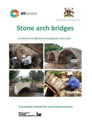
  • 1. Stone arch bridges A strong & cost effective technology for rural roads A practical manual for Local Governments Kasese District Local Government
  • 2. 1 Foreword This manual was developed based on the experience of the Belgian Technical Cooperation (BTC) supported Kasese District Poverty Reduction Programme (KDPRP) in Western Uganda, during the period 2009- 2013. The programme piloted stone arch culverts and bridges in rural areas, where low labour costs and high cost of industrial building materials favour this technology. The construction of stone arch bridges in Uganda, Tanzania & Rwanda has demonstrated its overall feasibility in East Africa. How to use this manual The purpose of this manual is to provide supervisors of stone arch bridge works with an easy step by step guide. The stepwise approach ensures adherence to quality requirements and construction methodology The main target audience of this manual is the road works supervisors and engineers employed by District Local Governments in East Africa. However, the manual remains relevant in the context of many other developing countries. Acknowledgements Many people and institutions contributed to this manual: the KDPRP steering committee, Local Authorities at District and Sub County levels, the District Executive Committee and the Chief Administrative Officer, William Kanyesigye. Special thanks goes to Paul Dequeker, Belgian architect, for having shared his broad experience in Congo with us. The manual was written by Eng. Sophie Grigoletto and Steven Hollevoet. The draft was reviewed by the Kasese District Works department, Alphonse Katswamba , Dave Renno, Ruediger Behrens (GIZ) and Neil Noble of Practical Action. Neil also produced some of the technical drawings. Jonas Geeroms edited some diagrams. BTC Uganda and the BTC junior programme made this work possible. Table of contents 1. Chapter 1: Introduction to stone arch bridges ..............................2 1.1Background and justification.......................................................2 1.2The stone arch bridge technology...............................................3 1.3Advantages & limitations. ...........................................................5 1.4Stone arch bridges: implications of labour-based technology....7 2. Chapter Two: Design of stone arch bridges...................................8 2.1Quick scan – site assessment ......................................................8 2.2Planning and stakeholders involved............................................9 2.3Design..........................................................................................9 2.4Site conditions and arch types. ...................................................9 2.5Calculation of the flow and the bridge span .............................11 2.6Bridge dimensions .....................................................................12 Roman arch bridge .....................................................................12 Segmental arch bridge................................................................13 Culverts.......................................................................................14 2.7Calculation of the quantities of materials.................................15 2.8Drawings....................................................................................15 3. Chapter Three: Construction of stone arch bridges ....................16 3.1Principle: wedging - only compression forces...........................16 3.2Steps of construction process ...................................................17 3.3Selection of construction materials...........................................33 3.4Implementation modalities and site management...................35 3.5Common construction mistakes................................................38 3.6Training of masons ....................................................................40 3.7Promoting the technology.........................................................40 4. References and further reading...................................................41 5. Table of Annexes..........................................................................42 Cost estimates, drawings, Memorandum of Understanding Technical Specifications, Assessment Checklist. This document has been produced in printed from, DVD, and as an online version of BTC http://intranet.btcctb.org and Practical Action http://practicalaction.org 2013
  • 3. 2 1. Chapter One: Introduction to stone arch bridges 1.1 Background and justification. Stone arch bridges are amongst the strongest in the world. The technology has stood the test of time. The Romans built stone arch bridges and aqueducts with lime mortar more than twenty centuries ago. Arches and vaults were also the determining structural design element of churches and castles in the Middle Ages (fig 1&2). There are stone arch bridges which have survived for hundreds and even thousands of years, and are still as strong today as when they were first constructed (see fig. 5). Fig 1: Vaults built in churches 14 th century Santiago de Compostela cathedral, Spain Fig 2: Ancient stone arches street medieval town of San Gimignano, Italy Picture: courtesy Wikipedia. The main reason that western countries moved away from stone arch bridges is because of the high labour costs involved in their construction. In industrialised countries, it is cheaper to use pre-stressed concrete rather than employ a lot of masons and casual labourers. In the economic environment of East Africa and the majority of developing countries, with low labour costs and high costs of industrial building materials, stone arch bridges provide a more affordable and practical option. Technology choice Adapted to following economic context Typical example Reinforced/ pre-stressed concrete bridges • High labour costs • Low cost of industrial building materials • Industrialised countries. • Highway contractors. Stone arch bridges • Low labour costs • High cost of industrial building materials • Rural areas in developing countries. • Community road projects Each financial year, districts and lower local governments are faced with funding constraints while the challenges in the rural transport sector are overwhelming. The limited available road funds are spent on costly public procurement of a few structures and road repair while most of the grassroots requests remain without support. Rural roads are often designed with an insufficient number of culverts due to the high cost of concrete culverts. It causes inadequate drainage and premature erosion, leading to increased maintenance costs of the road network. On the other hand, due to budget constraints, timber bridges are constructed with a limited lifespan of 4-10 years and the need for constant repairs. The adoption of stone arch bridges enables districts and lower local governments to improve the access to social services and markets of more village communities at 70% lower investment costs. Stone arch bridges offer a low-cost but strong technology that is appropriate for rural areas in developing countries.
  • 4. 3 Fig 3: Eroded road due to insufficient drainage capacity of the culverts Fig 4: Timber log bridges have limited span (10 to 12m) and lifespan (4 to 10 years). 1.2 The stone arch bridge technology Arch bridges are among the oldest types of bridges. Dating back to ancient China, Rome and Persia, this bridge structure has been in use for thousands of years. Because of the strength, many ancient bridges can still be seen today in cities of Europe and Asia. The Romans were the first to fully realize the potential of arches for bridge construction and built many spectacular arch bridges, over 2000 years ago (fig 5)! For local masons first exposed to arches, the concept remains abstract and shaky. The structure is completely unstable until the two spans meet in the middle and the arch is closed. From a layman’s perspective, it is hard to see how a bridge merely built with stones will support heavy traffic. However, the structure is ultimately rendered robust by the wedging principle of the stones that distribute the load as compression along the whole arch to the foundations. Tensile stresses are omitted. Fig 5: Roman stone arch bridge built over the Tagus River at Alcántara, Spain between 104 and 106.AD (Total length: 194m, longest span: 28m) Picture: courtesy Wikipedia. While there is quite some variety in arch bridge construction, the basic structure does not change. They can be architecturally different; but they are structurally the same. The simplest shape of an arch bridge is a semicircular design with abutments on each end. Its structure distributes compression through its entire form and diverts weight onto its two abutments. Tensional force in arch bridges, on the other hand is virtually negligible. Arch bridges do not need additional supports of reinforced steel. They are particularly suitable for building in stone because each of the elements in the arch will be under compression (fig 6).
  • 5. 4 Fig 6: Load distribution in a semi-circular arch: the weight on top of the arch is diverted to the abutments through the arch. The arch is almost entirely under compression without any tensile stresses. Single stone arch bridges can cover spans up to 20 meters. For larger spans, steel and pre-stressed concrete is required. Steel arches typically span between 50 and 250 meters, but West Virginia's New River Gorge Bridge built in 1977 has an impressive span of 518 meters (fig 7). Fig 7: New River Gorge Bridge, a steel arch bridge West Virginia, USA Picture courtesy Wikipedia. The construction of arch bridges all follow the same basic principle (fig 8), which is simple but requires some experience and training to ensure strong and long lasting structures. Stone arches are built over a temporary wooden formwork which holds the masonry in place during construction. The temporary form is needed since the structure is not stable until the arch is closed. The paragraph 3.2 gives more details about the different steps of the construction Temporary wooden formwork which is removed once the arch is closed. Arch with stones placed according to the radius of the semi circle. Abutment with stones laid flat with a good bond Fig 8: Basic elements of arch bridge construction. The arch is constructed symmetrically over a temporary formwork. Note that the arrangement of the stones differs entirely between the arch and the abutment. Stones of the abutments are placed in a flat and horizontal position while the ones forming the arch follow the radius of the circle. This arrangement is the key principle for the stability of the bridge.
  • 6. 5 1.3 Advantages & limitations. When compared to concrete bridges, stone arch bridges offer several advantages. A larger proportion of locally available resources are used in stone bridges as they can be built with local labour and stones. In contrast, raw materials and machines have to be imported for the construction of concrete bridges and specialized technical expertise is required. Compared to expensive aggregates, local stones are a strong, affordable material and they are often available in the vicinity (10-15 km) of the construction site. There is no need for expensive steel bars, aggregates, concrete or galvanised pipes that have to be hauled over long distances. Fig 9: Construction of a multiple-arch culverts with stones found in the vicinity As regards to the construction cost, concrete bridges require more capital and equipment (poker, concrete mixers). The cost of additional man-days required for the construction of stone arch bridges in rural areas is usually much lower than the higher cost of industrial materials and equipment used in concrete bridges as the table below illustrates. Construction Cost in Ush 2012 Cost in US$ 2012 Cost saving arch technology Bridge box culvert - public procurement span 4m 116,000,000 44,000 Stone arch bridge - forced account span 4 m 20,000,000 8,000 83% Reinforced concrete bridge – public procurement span 8m 250,000,000 95,000 Stone arch bridge - forced account span 8 m 39,000,000 15,000 84% Culvert 3 lines 75 cm diameter - public procurement 28,000,000 11,000 Triple culvert 80 cm diameter - forced account 5,900,000 3,000 79% Examples of cost comparison stone arch/concrete bridges, rural Uganda 2012- 1 US$= 2.650 Ush. The weight of the stone arch culverts reduces the risk of floods washing them away. The interconnecting arch and the heavy weight also prevent the tilting and sliding exerted by the backfilled soil mass - typical technical challenges related to concrete bridge abutments. Moreover, stone culverts cannot be stolen and resold, unlike galvanised or concrete pipe culverts. Compared to bridges made from tree logs, the stone arch bridges are more durable. They do not need to be re-built every 3 to 5 years. This makes the investment and community effort more effective, while the safety standard and traffic load capacity increase drastically. However, concrete bridges will be the right technology choice where labour costs are high and where large spans are involved. The maximum single span of stone bridges is usually less than 20 meters. For larger single spans, the volume of stone masonry becomes too massive and reinforced concrete is a better option.
  • 7. 6 SUSTAINABILITY CRITERIA STRENGTHS WEAKNESSES ECONOMICAL • No need for expensive equipment • Long lifetime • Low cost • Easy to maintain at local level • More expensive where labour and local stones are expensive. TECHNICAL • Stronger • Adjustable to local conditions • No traditional skills for arches, requiring prior training of masons SOCIAL/ POLITICAL/ CULTURAL • Technology manageable at community level. • New technology requires a change of mind- set and the sensitisation of the community and local governments. ENERGY BALANCE • Use of local materials, reduced use of industrial materials and dependence on long distance transportation • Higher energy cost than timber bridges due to use of cement but lifespan also 30 times longer. ECOLOGICAL • Limited use of timber as forests are under threat. • Maintains the beauty of the landscape as natural stone blends in well with the environment. • borrow pits for stone and sand might affect landscape and accelerate erosion but same applies to concrete bridges. There are some limitations to constructing stone arch bridges. It is important to assess the local context to make sure a stone arch bridge is the right solution. Where the cost of labour is high or where large quantities of stones cannot be found in the vicinity, the construction cost of a stone arch bridge could exceed the one of a concrete bridge. Another challenge is the capacity building of local craftsmen and contractors. Where no stone masonry tradition exists, masons need to be trained to master this technology and adhere to technical specifications. Fig 10. Vocabulary of arch bridges 1. Wing wall 2. Head wall 3. Spring 4. Key stone 5. Ring stone 6. Abutment 7. Shoulder
  • 8. 7 1.4 Stone arch bridges: implications of labour-based technology. Apart from the requirement of crossing a river, job creation is one of the objectives that this kind of construction can meet perfectly. The beneficiary community can indeed be integrated in the construction of stone arch bridges. Unemployment is usually high in rural areas of developing countries. Due to the high labour input required for the construction of stone arch bridges, seasonal employment can be increased. As the construction is simple, low-skilled labour can be used to implement the work. Unskilled workers from the villages collect stones and sand, masons build the bridges, and village carpenters make the simple scaffolding that is needed. It promotes employment, focusing on people and their skills rather than machines and imported diesel. Fig. 11: The community can be involved in the construction of a stone arch bridge. This approach enables also the involvement of the rural communities and district councils during the planning and execution of road works and results in a greater sense of ownership, self-reliance and community cooperation. The execution of the works can be delegated to village road committees. Villages can potentially access donor and government funding for road works through the matching of local resources. This approach favours the adoption of stone arch bridge technology by communities and also by local governments. The allocation of road funds based on effective community contribution is a more just principle than electoral campaign considerations based on patronage networks. Involving the community in the construction process is usually also one of the main challenges of the construction project. Successful bridge construction depends on a committed leadership and whether the bridge was identified as a top community priority. Without these preconditions, it is difficult to mobilise the community on a voluntary basis, especially where public procurement demonstrated a wasteful use of resources in the past. Next to the “force on account” approach, stone arch bridges can also be tendered through the public procurement system and contracted to construction firms. Still cost advantages will be important, as steel and concrete unit costs of conventional bridges are replaced by the much lower unit costs for stone masonry.
  • 9. 8 2. Chapter Two: Design of stone arch bridges 2.1 Quick scan: assessment of the grassroots request and site During the local government participatory planning and budgeting cycle, there are many demands for the construction of bridges. Some requests are politically motivated; others have strong socio- economic drivers. In the context of limited budgets, it is important to select the most economically relevant bridges which are strongly supported by the community. A preliminary survey will give a quick insight into the cost of the construction and the willingness of the community to contribute. Based on this data, the number of bridges in terms of the cost and the priority sites can be identified. Priority bridges can then be selected by the relevant local government bodies. Fig. 12: Site assessment The preliminary assessment should be carried with regards to: • Existing building skills and experiences of local craftsmen. • Demand analysis, acceptability amongst local inhabitants and community commitment. Is the bridge really a development priority of the local community? • Costs of labour and materials – vicinity of borrow pits for stones, sand and murram. • Technical site characteristics: • Hydrology (Flood, discharge, river profile, risk of erosion, etc) • Sub-soil - test pits to assess bearing capacity • Previous bridge and road works by the community • Level of skills means of local contractors and craftsmen • Economic activities of the area – socio economic justification for the construction as compared to mere political demands. • Crop production: cash and food crops. • Existing markets and trade centres • Improved access to schools and health facilities • Population density – number of village benefiting • Expected future traffic A checklist intended to help planners and technicians assess the feasibility of a proposed bridge construction project can be found in the annex 6.
  • 10. 9 2.2 Planning and stakeholders involved. Multiple stakeholders are involved in a construction project. The benefiting community will actively participate in the construction. They are organized in a road committee. An entrepreneur can be contracted to implement the construction, or a mason, assisted by casual labourers from the community. Local governments at sub-county / ward and district levels are involved at every step of the process. Each stakeholder has its responsibility to ensure the implementation of the project. The structural analysis and drawings are prepared by the district works department. Entrepreneurs or qualified mason are trained and contracted for the implementation of the works. Tools and cement are provided by the district. Local building materials like stones, sand and murram can be collected by the community, coordinated by their road committee. They can also provide labour for the site clearance, excavation, trenching, compacting and backfilling, under the supervision of the works department. The lower Local Government is responsible for the mobilization of the community. The construction is monitored by the District Works Department, assisted by the lower local government. The road committee reports to the district in case of problems with the quality and quantity of the works provided by the masons and/ or contractor. A Memorandum of Understanding (see annex 4) is signed between the lower local government, the community and the district. It gives more details about the possible responsibilities of each stakeholder and the implementation modalities. It is an important tool for improved communication and planning. 2.3 Design The following recommendations aim at helping planners and technicians with the design of a stone arch bridge on rural feeder roads. Standard design tables were adopted as outlined in the tables of paragraph 2.6. These design parameters are based on the work of architect Paul Dequeker in the Democratic Republic of Congo (reading reference 14) and the design manual of the French Ministry of Works (reading reference 9). For further strength analysis, the doctor thesis of Alix Grandjean (Lausanne 2010 - reading reference 1) gives an excellent background. 2.4 Site conditions and arch types. Site conditions determine the type of the arch: • Roman arches (i.e. half circle) are the strongest and the simplest to construct. They are the favoured option where gully or riverbanks are high enough to allow for large radiuses within the bridge span. • Segmental arch bridges (only a circular segment) are the necessary design option in lowlands and flat valleys. They avoid that the bridge will stick out as a large hump and that large quantities of murram will have to be hauled for the road approaches. Segmental bridges are structurally less strong than roman arches.
  • 11. 10 Fig. 13: Recommended bridge type in function of the landscape and river crossing. Site conditions Recommended arch type High riverbanks gullies (Height of the riverbank is larger than 1/3 of the bridge span) Roman arch Flat areas Low river banks Valley grounds Segmental arch Wide rivers with rock formations in the river bed Multiple roman arches with piers on the rocks in the river bed Wide rivers 15 metres Segmental arch Road drainage. Narrow brook and gullies 1 metre Single arch culvert Swamps and brooks. Irrigation canals. Sub soil with weak bearing capacity. Multiple culverts vented drifts
  • 12. 11 2.5 Calculation of the flow and the bridge span The opening of the arch bridge should allow the river to pass through it. By examining the riverbanks and asking local residents the highest flood water levels they have observed, the maximum discharge of the river can be calculated. The section of the opening should be equal to the surface of the trapezoid outlined by the highest water level (fig. 14). From there, the required span of the bridge can be calculated, taking into account the site conditions. The opening should be wide enough to minimize constriction of the natural channel. But it should not be too wide, as this could encourage river deposits likely to modify the flow of the river. In addition, there is no advantage of constructing a bridge taller than the highest flood level. Beyond that point, no water will be evacuated unless the road is raised and the bridge span increased. Fig. 14: Left side: river profile at highest water level. Right side: Roman stone arch bridge with an equivalent opening. Hatched surfaces have the same area, i.e. the area of the river section at highest water level. The radius of the required roman bridge can easily be calculated: The construction of sufficient large bridges to allow for the discharge of floods will not be a problem for rivers with high banks. However, in low laying valleys with small river banks, there is usually a conceptual problem. On one hand, the areas flood and large bridge openings are required to absorb the water flow. On the other hand, a large bridge will constitute a high hump that will be an obstacle to traffic and require a lot of costly backfilling. A balance needs to be struck between the two construction considerations. Low valleys will often entirely flood during the peak of the rainy season. Under these conditions, the road level needs to be raised considerably, which is often more expensive than a bridge structure itself. Alternatively, the bridge can be relocated to a more suitable site or several bridges can be built in series over existing river arms or a vented drift should be designed. Due to their heavy weight, stone arch bridges resist well floods provided that their foundations are protected against erosion. During the torrential floods in Kasese in May 2013, none of the arch bridges was damaged while many other conventional structures were damaged.
  • 13. 12 2.6 Bridge dimensions Roman arch bridge The dimensions of a Roman arch bridge can be determined from the table below, as a function of the required span (2R). The dimensions are for a maximum traffic load of 40 tons. The roman arch bridge is the strongest design. Fig. 15: diagram, formwork and example of a roman arch bridge Span (m) Thickness keystone Thickness at 30° Radius extrados Thickness abutments Height abutments Min. Depth foundations Masonry volume (incl. foundations) /m Masonry volume (incl. foundations) for 3m width 2R V v r E H h m³ m³ 1 0.28 0.75 4.00 0.44 0.63 0.50 2.32 6.97 2 0.30 0.82 3.38 0.63 0.91 0.60 3.79 11.36 3 0.33 0.89 3.70 0.83 1.19 0.70 5.40 16.19 4 0.35 0.96 4.19 1.02 1.48 0.80 7.16 21.47 5 0.38 1.02 4.74 1.21 1.76 0.90 9.07 27.20 6 0.40 1.09 5.32 1.40 2.05 1.00 11.13 33.38 7 0.43 1.16 5.91 1.59 2.33 1.10 13.33 40.00 8 0.45 1.23 6.51 1.78 2.61 1.20 15.69 47.07 9 0.48 1.30 7.11 1.98 2.90 1.30 18.20 54.59 10 0.50 1.37 7.72 2.17 3.18 1.40 20.85 62.55 11 0.53 1.43 8.33 2.36 3.47 1.50 23.66 70.97 12 0.55 1.50 8.94 2.55 3.75 1.60 26.61 79.83 13 0.58 1.57 9.56 2.74 4.04 1.70 29.71 89.14 14 0.60 1.64 10.17 2.93 4.32 1.80 32.97 98.90 15 0.63 1.70 10.79 3.13 4.60 1.90 36.37 109.11 Source: Dequeker Paul, Architect Width For rural feeder roads, the standard width of a bridge is 3.6 meters, which allows for single lane crossing of lorries. Height The roadway should be above the flood level, which can usually be determined by examining the riverbank and asking local people the highest water level they have observed. If necessary, the bridge must also provide an adequate clearance for boat passage.
  • 14. Segmental arch bridge It is possible to increase the span up to 20m bridge is practical for flat valleys and larger spans. arch. The bridge dimensions for a maximum traffic load Fig. 16: Diagram, formwork L (m) F R 1 0.20 0.72 2 0.40 1.45 3 0.60 2.17 4 0.80 2.90 5 1.00 3.62 6 1.20 4.35 7 1.40 5.07 8 1.60 5.80 9 1.80 6.52 10 2.00 7.25 11 2.20 7.97 12 2.40 8.70 13 2.60 9.42 14 2.80 10.15 15 3.00 10.87 16 3.20 11.60 17 3.40 12.32 18 3.60 13.05 19 3.80 13.77 20 4.00 14.50 13 increase the span up to 20m by using another arch shape. bridge is practical for flat valleys and larger spans. The segmental arch is less strong than the roman for a maximum traffic load of 15 tons are given in the table below. , formwork and example of a segmental arch bridge. V r v E H m³/m 0.28 3.37 0.52 0.64 0.38 2.77 0.31 3.59 0.60 0.94 0.43 4.54 0.34 4.29 0.67 1.23 0.48 6.36 0.38 5.09 0.74 1.50 0.53 8.28 0.41 5.93 0.80 1.76 0.58 10.33 0.44 6.78 0.87 2.02 0.63 12.50 0.47 7.65 0.93 2.28 0.67 14.80 0.51 8.52 0.99 2.54 0.72 17.25 0.54 9.39 1.06 2.79 0.77 19.83 0.57 10.26 1.12 3.05 0.81 22.55 0.61 11.14 1.19 3.30 0.86 25.41 0.64 12.02 1.25 3.56 0.91 28.42 0.67 12.90 1.32 3.81 0.95 31.57 0.70 13.78 1.38 4.06 1.00 34.86 0.74 14.66 1.44 4.32 1.04 38.29 0.77 15.54 1.51 4.57 1.09 41.86 0.80 16.42 1.64 5.08 1.18 45.65 0.83 17.30 1.64 5.08 1.18 49.43 0.87 18.19 1.70 5.33 1.23 53.44 0.90 19.07 1.77 5.58 1.28 57.58 Source: Dequeker Paul, Architect . The segmental arch The segmental arch is less strong than the roman are given in the table below. segmental arch bridge. Vol. m³/m Vol. m³ for 3m width 2.77 8.31 4.54 13.62 6.36 19.08 8.28 24.84 10.33 30.99 12.50 37.50 14.80 44.40 17.25 51.75 19.83 59.49 22.55 67.65 25.41 76.23 28.42 85.26 31.57 94.71 34.86 104.58 38.29 114.87 41.86 125.58 45.65 136.94 49.43 148.29 53.44 160.32 57.58 172.74 Dequeker Paul, Architect
  • 15. 14 Culverts. Expensive and fragile concrete culverts can be easily replaced by stone arch culverts. They are usually 60% cheaper than conventional galvanised or concrete culverts. They cannot be stolen and do not break during construction or transport. In valleys, they do not need a large soil buffer as concrete pipes. It is recommended to use a standard mould of 80 cm span that can be re-used. The height of the culvert is adjusted to suit the discharge and river banks. For ease of access, an 80 cm semi-circular span with 60 – 80 cm height abutments is a convenient size. The width of the abutments should not be smaller than 30 cm. The depth of the foundations should not be smaller than 40 cm. The setting out of the abutments should be done with the moulds in place. A gap of about 2 cm is left between the mould and the abutments. The gap will allow for the swift removal of the moulds once the arch is finalised. A gradient of 2% of the base will facilitate the self-desilting of the culvert. Drawings of some culverts can be found in annex 2. Fig. 17: Single stone arch culvert - dimensions in cm. Multiple arch culverts can also be used for spans bigger than 1m, where a stone arch bridge would be much higher than the level of the road, requiring an excessive quantity of backfilling for the road approaches. This is usually the case in flat valleys and swamps. During flooding the small diameters of the culverts will be blocked with logs and debris. They need frequent cleaning. Fig. 18: Multiple stone arch culvert- - dimensions in cm.
  • 16. 15 2.7 Calculation of the quantities of materials. Materials are calculated in order to make a Bill of Quantities and estimate the cost of the construction. It can be done with the Excel spreadsheet given in the annex 1, as a function of the design parameters. The cost can also be estimated. Unit prices need to be adjusted according to the local prices. The volume of stone masonry for the arch, abutment and foundations of roman arch bridge and segmental bridge are also given in the last columns of the above tables. Basic quantity guidelines: • Stone requirement: theoretical volume of the structure +10%. A 7 tons lorry carries 3.5 m3 of stones. • Cement requirement: 1.5 - 1.8 bags per m3 stone masonry for 1:3 mix. • Water requirement: less than 20 lt per bag of cement. In addition, large amounts of water are required for curing of the stone masonry. • Labour: 1 mason with 2 casual labourers construct 1.3- 1.6 m3 stone masonry per day There are large variations to the above recommended data: • Well organised and skilled masons will construct larger volumes per day. • The cement requirement will be much higher if small stones are used or the mason is not filling the gaps with small pebbles but only with mortar. • Large stones help to reduce cost, speed up the work and increase the strength of the bridge. 2.8 Drawings Examples of AutoCAD drawings are given in annex 2. They can be used as models and be modified to suit the design parameters. Other elements can of course also be added depending on local conditions (concrete cap when no soil buffer, stone pitching in the river bed, etc). Fig. 19: diagram stone arch bridge with components
  • 17. 16 3. Chapter Three: Construction of stone arch bridges 3.1 Principle: wedging - only compression forces A simple beam will bend as a reaction to a load. This change in the beam’s shape causes the bottom of the beam to become stretched in tension, the top of the beam to be squashed in compression. These opposite forces in the beam can cause the beam to tear apart with relatively small forces when materials with low tensile strength are used, such as stones or plain concrete. The arch form is one of the earliest and historically ingenious solutions of dealing with tensile stresses. Fig. 20: beam bending under a load. The semicircular arch developed by the Romans was a great technological achievement in bridge design. The strength of the arch bridge comes from its shape. The shape of the arch is designed so that, when loaded, every component is in compression, and ideally there is almost no part of the structure in tension. Instead of pushing straight down, its semicircular structure carries the load outward along the curve through its entire form and diverts weight onto its two abutments. The supports at each end of the bridge directly take on pressure. These abutments and well compacted backfilling prevent the arch from bending outwards when heavy loads press down on it. As a result, the arch is always under compression, maintaining its shape and stability. Fig. 21: Forces in an arch bridge. An arch can carry a greater load than a horizontal beam of the same size and material, because downward pressure forces the stones together instead of trying to force them apart. All the compressive forces hold it together in a state of equilibrium. By using the arch configuration, significant spans can be achieved. However, an arch pushes outward at the base, and this needs to be restrained with heavy abutments and well compacted backfilling. Masonry arch bridges need backfilling material above the arch in order to increase the dead-weight on the bridge and prevent tensile stresses from occurring in the arch ring as loads move across the bridge. Loaded bridges with plenty of backfilling are the strongest.
  • 18. 17 3.2 Steps of construction process 3.2.1 Site selection It is recommended that the existing bridge site is thoroughly examined. Traditional pole bridges are often located at the narrowest river crossings which are not necessarily the best construction sites for permanent bridges. The following factors are taken into consideration for the site selection: The bearing capacity of the subsoil. Sites with rock layers provide important advantages, as the cost for the foundation will decrease considerably and future erosion damage will be prevented. It is usually more cost effective to move an earth road rather than building a bridge on an existing site that has no firm sub soil or that is prone to erosion. Sandy and clay soils and sites with springs, muddy ground and swampy terrain should be avoided as they will require improved reinforced or sometimes even piled foundations. Small trial pits are dug to assess the bearing capacity of the sub soil. The bearing capacity varies in function of the moisture level and soil type. Laboratory test to establish the shear strength and consolidation of the soil are recommended. Alternatively, in the absence of such services, the chair test can be used. This method consists of adding cement bags on a stool (with a known surface area of its legs) till the legs enter the soil by 2-3 cm. The test is done in a trial pit at foundation level. The bearing capacity of the soil in kg/ cm2 is then calculated by: 0.33* number bags * 50Kg Cross-section legs in cm2 0.33 is the safety factor 3. The conversion rate from kg/ cm 2 to kN/m2 is about 9.8. Minimum required bearing capacity of sub soil as function of the bridge span traffic load – values at foundation level Span bridge traffic load 40 tons traffic load 20 tons L(m) in kN/m 2 In kg/cm 2 in kN/m 2 In kg/cm 2 1 132 1.35 77 0.79 2 113 1.15 72 0.73 3 108 1.1 74 0.75 4 109 1.11 80 0.81 5 113 1.16 88 0.9 6 121 1.23 98 1 7 129 1.32 109 1.11 8 139 1.42 121 1.23 9 150 1.53 133 1.36 10 161 1.64 146 1.49 11 173 1.77 159 1.62 12 185 1.89 172 1.75 13 198 2.02 186 1.89 14 211 2.15 200 2.03 15 224 2.29 213 2.17 16 238 2.42 227 2.32 17 246 2.5 236 2.41 18 265 2.7 256 2.6 19 279 2.85 270 2.75 20 293 2.99 284 2.9 Source: Cornet 2013
  • 19. 18 Bearing capacity of some soil types in Kasese District Soil type depth av. allowable bearing capacity kN/m 2 area clayey sands 2.5 210 Nkoko / Karusandara clayey silty gravels 3.0 340 clayey gravels 3.0 110 Kyempara / Isango clayey sands 4.0 155 poorly graded gravel silty gravel 2.5 635 Kyabayenze/ Karambi silty sands 3.0 740 inorganic silt 3.5 770 silty sands 2.0 735 Katumba / Bugoye silty sands 3.0 1000 clayey sand and clays 3.5 400 Kanyamunyu / Kitholhu silty gravels 2.0 450 Kaghema / Kyarumba silty gravels 2.5 695 silty gravels 3.0 845 silty gravels 4.0 730 clayey sands and poorly graded sands 3.0 730 Kabuiri / Maliba clay 3.5 695 poorly graded sands 4.0 755 Source: MBW 2012 – safety factor 3 applied. Flood prevention It is advisable to construct a bridge on a slight sloping terrain in the landscape rather than on the edge of the valley where water accumulates and risk of floods and meandering is higher. High river banks reduce the risks of flood levels exceeding the bridge and of the by-passing the structure by the river. Avoid river bends The crossing must ideally be located where the river is straight, stable, and not meandering. This will reduce the maintenance costs considerably. In a curve, the river will cause heavy scouring or will break through its banks and by-pass the bridge. Road approaches For low rural traffic densities, the best position of the bridge vis-à-vis the river (i.e. square on the river axis) is more important than the alignment with the existing road approaches. The site for the bridge is selected in such way that no large quantities of backfilling are required for raising the level of the road. Backfilling of road approaches can be very costly as it often requires heavy machinery. High river banks For arch bridges where tilting force of the soil mass has no effect on the stability of the structure, high river banks usually offer important advantages: • The roman arch type can be adopted which is a stronger design than the segmental one. • Larger bridges can be constructed to absorb the full discharge of even the largest floods. • Less material is required for backfilling and the construction of road approaches. • With high river banks, the probability of a meandering river or bursting banks is lower. • Usually easier traffic access, as the approaches will not be on a steep slope. High river banks are sometimes an indicator for increased erosion risk and adequate mitigation measures should then be put in place (see 3.2.9).
  • 20. 19 3.2.2. Site preparation For large bridges, the community will need time to deliver the materials before the actual construction starts. It is good practice to peg out already the actual site of the bridge. In addition, the technician should peg out the locations where sand and stones should be delivered by the village. The site plan is discussed with the village so that building materials are dumped in a systematic way without hindering access to the site and optimising transport cost during construction. Construction is best done during the dry season. Transport of building materials is then easier and costs for river diversion, digging the foundation pith of sufficient depth and flood prevention can be minimised. Village labour is also more available during the dry months. It is good to avoid construction during the rainy season; as flood risks are hard to control. Site preparation starts with site clearing (stripping topsoil, slashing the vegetation, cutting down trees and removing the roots). Clearing vegetation is a basic task performed by the community. On the river banks, heavy bush clearing and the unnecessary cutting down of trees should be avoided as they will help to prevent erosion in the future. Existing grass tufts should not be destroyed. They will be planted on the steeps riverbanks to stabilize the soil after construction. If possible, the existing local bridge is left intact to facilitate the movement of building materials. Alternatively, a temporary bridge might need to be constructed where the traffic cannot be interrupted. It can be made with logs placed across the river. If necessary, the river will be diverted with coffer dams, notably to allow for foundations of sufficient depth and provide for stone pitching of the river bed where required to prevent scouring. Coffer dams are usually erected to prevent the flooding of the excavation pits. Coffer dams will be made of bags filled with soil and stones. In function of its height, the bottom of the coffer dam will be 2-3 bags wide to improve stability. In case of flood risk of large rivers, the bags will be supported by spiked poles and heaped stones walls or temporally placed gabions. The size of the diversion canal is a function of the river flow. The verge of the canal is dug at 60% degrees to avoid the collapse of the walls. Excavated soil is “stored” properly to facilitate the filling of the diversion after construction. If possible, the dam is made at sufficient distance from the construction site to prevent flooding. River diversions are best avoided during the rainy season as the floods can make deep gullies causing the stream to by-pass the bridge altogether. To prevent scouring of the diversion canal during floods, gabions can put across the canal bed to obtain a stepwise discharge. Alternatively, galvanised culverts are temporary used to avoid erosion. 3.2.3. Setting out and excavation Once the location of the bridge has been determined, the river banks and the foundation trenches are excavated. During excavation, it is important to ensure that any water which may enter the trench can run off or should be pumped out. After digging, the bottom of the pit shall be compacted with a heavy steel compactor or a jumping compactor. The excavation pit will provide for an allowance of about 1 metre each side to enable the access of the craftsmen. In most cases, a water pump is required to remove the excess water and reach the required foundation depth. To avoid the river banks collapsing, the slope of the excavation should be at least 60 degrees. For unstable soils, the excavation should be done in steps or the walls should be temporally shored by timbering and struts.
  • 21. 20 For larger rivers that cannot be diverted, the excavation is usually done in 2 phases. Only one bank of the river is shut off with a coffer dam to reduce the water level and allow for excavation. Then the foundation and abutment at that bank are built. The coffer dam is then moved to the opposite river side and the process repeated. Shutting off both river banks at the same time drastically increases the risk for flooding of the excavation pit and foundations and should be avoided unless construction is done in the middle of the dry season. The bridge foundations must be carefully set out. Measurements are made and checked with two measuring tapes and a calculator (see figure 22). Based on the Pythagoras’ theorem (squared hypotenuse equals the sum of the squared length and squared width), the diagonal can be calculated and square angle obtained. To make sure that a corner is a right angle, the 3-4-5 method can also be used, but it is a bit more time consuming. Pegs are put in the ground and string or cord is tied to them, to show the mason the width of the foundations. These marks must be durable, so that they remain accurate for a long period of time and are not destroyed by rain or workers activities. A straight trench is dug out between the lines. Before digging, it is necessary to check the orientation of the lines, the dimensions and the right-angles using a measuring tape and a square. Fig. 22: Setting out the foundations with 2 measuring tapes speeds up the work. The measuring tapes will help to get the right angle based on the Pythagorean Theorem. Z 2 =A 2 +B 2 . In a triangle of 90 degrees: the square of the hypotenuse is equal to the sum of the squares of the other two sides. Alternatively, use the 3-4-5 method which is more labour intensive: 5² = 3²+4². Excavation, loading and hauling tasks can be performed by the community, using shovels, pick axes and wheelbarrows. The workers are instructed not to dump the excavated soil in the river. Excavated materials will be kept near the construction site so as to be re-used later for backfilling, although more material will usually be needed. The excavated soil should be dumped where the road approach. To prevent collapse of the construction pit, excavated soil is dumped at least 6 metres from the trenches so that no extra weight is added to the earth wall. 3.2.3. Foundations and abutments The lifespan of a bridge depends essentially on the strength of its foundations. The strongest bridge will have a short lifespan if its foundations are eroded by the river. Masonry work for foundations will be carried out with particular care and under strict supervision. The substandard work of many local masons (low dosage cement in mortar mix, no use of batch box, excessive water amount in mix, poor bonding of stones, air gaps, no stone washing...) should not be tolerated. The technical 2 measuring tapes river bed foundation 2 foundation 1
  • 22. 21 specifications and quality will be strictly enforced, as the structural strength of the bridge depends on it. Masons not able to adhere to higher quality requirements should be replaced immediately. With stable sub soils, foundations are made of stone masonry. Their height should be determined on site once firm subsoil is reached. The design tables (figures 15 16) give only minimum depths. Apart from sites with solid rock beds, the foundation depth will exceed the depth of the river bed. On sites with poor bearing capacity (permanent waterlogged places, sites with high content of clay and sand), a reinforced foundation slab or footing will be necessary. On muddy and unstable sites, different techniques exist of constructing piles of mass concrete. One of them is the use of well foundations: a well is built with bricks. A base ring made of reinforced concrete and is bevelled to facilitate the penetration of the cylinder into the ground. Another solution is the construction of concrete rings. They are dug into the ground until a firm sub soil layer is encountered. The rings are then filled with mass concrete as foundation pillars. Reinforced concrete boxes can also be constructed upstream on the riverbanks, and moved by floating. However, this requires specialised skills beyond the scope of this manual. Fig. 23 a: The quality of stone masonry is essential. A good bond of stones and tight gap filling will provide for a strong abutment. In addition, at the river corners dents are left for a good link with the wing-walls. Fig. 23 b: Extremely poor masonry works – no bond at all, plenty of gaps between the stones, no embedding of stones with mortar. Sections like those need to be demolished immediately and the mason replaced. Stones for the foundations and the abutments are placed in a horizontal position (see fig. 8, fig. 23 a, fig. 24), laid down on the largest side of the stones enabling a good bond. The selection of the well shaped stones is important in order to minimize the quantity of mortar and improve the strength of the bridge. Stones are wedged against each other to reduce the number and size of holes to be filled in with mortar. The foundation and abutments require large stones – ideally rectangular shaped. Masons will work with “stone spotters”. From the stone piles, these casual labourers specialise in identifying the stones of the right shape and size that fit in the existing masonry gap. The stones are washed with a hard brush and wedged against each other to reduce the number of holes to be filled in with mortar. Gaps between the stones need to be filled with crushed stones and mortar. Mortar is laid where necessary, rather than just poured over the stones. All stones should be well embedded in mortar. The practice of local masons to allow some dry touching of stones should not be tolerated. As the foundation and sections of the abutment are permanently exposed to damp conditions, a mortar mix of 1:3 is a must. For the sections of the foundation under the water table, a 1:2 mix is required. Poor quality sand will require a higher cement dosage. Untrained craftsmen will usually b: wrong bonding a: correct bonding
  • 23. 22 put too much water in the mortar to enhance workability. However, wet mortar mixes will lead to poor strength. The maximum amount of water is 20 litres per 50 kg cement bag. Fig. 24: Different positioning of stones in the structure Arch = stones along radius of the semi-circle Abutment foundation = stones are laid flat 3.2.4.Formwork For building an arch, a semi-circular formwork of the same shape as its interior curve (intrados) is required to support both spans until they lock together at the top (see fig. 8, fig. 24 and fig. 25). The frame, called centring, is removed after the stones are in position. The formwork is usually made of wood; but soil on a wooden platform is also possible. The wooden formwork is used with wedges so that it can be easily removed once the arch is complete. The formwork resembles the trusses of a roof, only that its top shape is circular and that usually it is made of 2 parts. The wooden formwork is made up of 2 individual trusses (see fig. 25.b) that are linked in the middle. The trusses are usually made of 2*4” timber (50*100 mm). For longer spans 2*6” (50*150 mm) will be required. The trusses are supported by transverse struts and poles. For the average bridge width of 3.6 metres, 5 “double” trusses are required. The trusses are covered by 1*3 timber purlins. The purlins are jointed tightly without gaps to avoid mortar being wasted. Fig. 25: Each truss of the form work consists of 2 pre-fabricated quarter circles that are assembled at site.
  • 24. Fig. 27: The correct curve of the truss i struggle with the principle and the process will need technical guidance. B: wrong formwork consisting of a set of Fig. 28: Once the first mould is constructed, the others are easily copied and shaped with a: correct 23 . The correct curve of the truss in a function of the span and the type of arch is important. Many carpenters struggle with the principle and the process will need technical guidance. A: correct shaped formwork. g formwork consisting of a set of straight lines. This latter formwork had to be demolished. the first mould is constructed, the others are easily copied and shaped with a machete. Fig 29: five trusses are required for a standard width of 3.6 m. The trusses are Fig.26: The wooden formwork is made up of 2 indivi trusses that are then connected beam. The floorboards are placed dir Each wooden structure rests on 2 wedges easing the removal of the formwork. Fig 26 a: formwork for a roman arch. Fig 26 b: formwork for a segmental arch for large spans. n a function of the span and the type of arch is important. Many carpenters : correct shaped formwork. had to be demolished. trusses are required for a standard width The trusses are supported by struts. b: wrong is made up of 2 individual in the middle with a tie- loorboards are placed directly on the trusses. wooden structure rests on 2 wedges easing the removal Fig 26 a: formwork for a roman arch. Fig 26 b: formwork for a segmental arch for large spans.
  • 25. 24 Fig. 30: Steps of assembling the formwork 1. With help of rope and pencil, ¼ of a circle curve is drawn on newspaper sheets that were pasted together. The paper mould is then cut out and will be used for the first wooden mould. The radius for the curve can be found in the design tables – figures 14-15. The rope will have the length of 2R of the design tables. For larger spans, the formwork will consist of 2 moulds. 2. The timber frame is constructed by putting the timber struts along the paper mould. The curved shape can be obtained with a saw or by hand with a machete/ chisel. It is critical that the shape of the arch mould is a curve and not a set of straight lines at different angles. Untrained carpenters will initially construct the latter which should be immediately corrected. 3. Once the first mould is obtained, the others are simply copied by drawing the original shape on the consecutive trusses. 4. On site, the quarter trusses are assembled into a half circle by struts. This formwork is levelled and supported by poles. Purlins are nailed on the trusses to finish the formwork. 5. It is important that the trusses rest on 2-3 wedges. Without the wedges, it will be impossible to remove the formwork without damaging the timber once the stone arch is constructed. The drawings were produced by Neil Noble - Practical Action/ UK
  • 26. 25 Fig 31.: Left: If there is a risk of heavy flooding, additional anchoring of the scaffold is required. Timber poles (A) stretching across from one abutment to the other will hold the scaffold together. They are the basis for additional poles which are nailed parallel with the abutments in the river bed. A large opening (B) should be left in the middle where the debris can pass. Right: The poles of the formwork in the middle caught the debris of the first seasonal floods. The water flow was blocked leading to serious damage and the river by-passing the structure. Fig 32: This formwork was constructed on site during the dry season. The span of the bridge was 50 metres and consisted of 5 arches. A rope was used to get the curved shape. The pictures are a courtesy of Rashid Mtamila/Tz. Formwork for culverts Fig. 33: The moulds for culverts are standard (here 80 cm diameter and 2 metres long). They can be re-used many times. The culvert size can be adjusted in function of the site conditions (banks, water flow) by increasing the abutment height or having multiple structures. B A
  • 27. 26 The formwork can be removed immediately after closing the arch – there is no need to wait for the curing of the mortar. The scaffold can therefore be reused straightaway for culverts or multiple arches. It makes sense to construct a precise and robust formwork so it can be re-used. The district works office can store the trusses and culvert moulds so that they are available for future use. Painting the timber with used engine oil will increase the life span. Alternative types of formwork Where carpentry skills are not sufficient to build trusses, a full panel system can be used, but it consumes more timber (see fig 34). Building up bricks or blocks with dry joints and shaping the curve with a layer of mortar is a very economical way of making a formwork. When timber is too expensive, a further alternative is to use the “lost soil method”. The abutments are first built up and a platform is built between them. Then the inside of the culvert is filled with earth shaped on top to the correct profile for the underside of the arch (intrados). The earth provides temporary support for the arch stones during construction and is removed later (see fig 35). Fig 34 a full panel form work is easier to construct but more expensive and less strong. To reduce construction costs, the formwork was removed to build the 3 arches consecutively. Fig. 35: Making of formwork with the “lost earth method”: A platform is built between the abutments. Wooden panels at both sides cut along the intern curve of the arch, drawn thanks to a rope fixed to a nail in the circle centre. The inside of the culvert is then filled with earth contained by two wooden panels, and shaped on top to the correct profile.
  • 28. 27 3.2.5. Arch – the wedging principle. The arch shape is made from a series of wedge-shaped stones carefully chosen to fit together. These stones are set side by side on the formwork, and gradually take the curve of the arch from the outermost horizontal springs, the two points where the arch rests on its supports, up to the central and vertical 'keystone’. Stones of the arch are placed in a radial position. Stones should act like a wedge: the small end should be on the inner radius of the arch and the larger end at the outer. Once the stones are in position, it is recommended to tap with a hammer so that they slide tightly into place and mortar is better spread in the gaps between the stones. Fig 36: Stones of the arches are placed along the radius of the arch, the small base down and the larger base up, while stones of the abutments are set in a horizontal position, put down on the largest side of the stones. It is usually not necessary to chisel the stones, but the selection of well shaped stones is crucial. They should be flat and long especially in the upper section of the arch. More details about the required quality of the stones are given in section 3.3. Fig. 37: Correct position of the stones along the radius of the arch. Stones of the arch are placed in a radial position, squared to the scaffold. A mason square indicates the correct position of each stone, provided the formwork is even. For culverts, a rope fixed in the centre of the circle can be used to show the right direction. 90 degrees
  • 29. 28 During the closure of the arch at the top, it is essential that: • The best shaped stones (long flat) are preserved for closing the arch (see fig 44). They should not be used in early construction stages, as they are essential later. • Stones are laid along the radius of the circle. Building squares help to get the right position. • The stones are tightly wedged-in with a hammer and all gaps are filled with mortar (see fig 38). • The minimum key stone dimensions (see tables 15 16) must be respected. Fig 38: Left: Building squares show the right position of the stones during each phase of the arch construction. Right: It is of utmost importance to fill all gaps between the stones. Small stones will be added to the mortar to reduce cement costs and increase strength. Fig 39. The quality of the craftsmanship is of extreme importance for the strength of the arch. Left: Good bond and proper positioning of stones. Right: poor stone masonry that will result in a weak structure. correct wrong Building square fill
  • 30. 29 Fig. 40: a: Stones are tightly put together. They should act as a wedge with the narrow base pointing downwards. Fig 40 b: The keystone is wrongly placed. As the large base is at the bottom, the stone will fall out over time. The arch construction must start from both sides at the same time, and is assembled symmetrically up to the keystone, which is positioned last. The formwork can be removed as soon as the arch is closed. It is easy to remove the formwork that was placed on simple wedges of timber cut-offs. The formwork can be re-used. Fig. 41: For stability reasons, the bridge is built symmetrically, stepwise from both sides at the same time (a). It is dangerous to construct only one side first (b). The structure is not secure until the arch is closed in the middle. 3.2.6. Headwalls Head walls are constructed to protect the backfilling from water damage and guide traffic along the crossing. They are made of stones masonry and are positioned downstream and upstream sides of the bridge. They are made of 30cm thick stone masonry. For bridges of a long span, rain water drainage holes at the right level should be provided for. 3.2.7. Wing walls The wing walls act as retaining walls for the riverbanks and protection against scouring. They are interlocked with the masonry work of the abutment. Wing walls are provided at both ends of the abutments to provide smooth entry of water into the bridge site and to retain the backfilling of the approaches. Their design (position, orientation and length) is determined on site, in function of the natural landscape. They are preferably constructed in steps, at the same time as the abutments. It is not recommended to build wing-walls higher than 2 metres in one go. This would require a heavier base than the usual 40 cm thickness of the stones. Wing-walls with deep foundations are often a better investment than gabions which usually sag and tumble after minor under scouring. a: correct b: wrong a: correct b: wrong
  • 31. 30 3.2.8. Backfilling: an underestimated construction step. The strongest arch bridges are those that are permanently loaded with compacted backfilling material. Ideally, there is a soil buffer above the arch to cushion the impact of moving heavy traffic and increase the load. Backfilling material (typically compacted gravel or laterite soil) is compacted above the arch in order to increase this dead-weight on the bridge and prevent tensile stresses occurring in the arch ring as loads move across the bridge. A minimum of 30cm of filling should be added on top of the arch, but the quantity will vary as a function of the site conditions (level of the road and height river banks). If insufficient backfilling can be provided (to avoid large humps in flat valleys for instance), it is recommended that a concrete cap of 10 cm thick and 2 metres in length is cast on the top of the middle section arch. . The backfilling should be placed in 10 cm layers of murram and then heavily compacted. The workers will use an iron compactor, a tractor axle or a long handle with a cast iron weight at the end. The usual timber or light metal compactors are not effective at all and should be banned. Even an eucalyptus pole will do better than those. A lot of manpower and direct supervision is needed to produce a compaction of reasonable quality. The soil layers should have the right moisture content and should not be too thick. A jumping compactor will provide for the best compaction. A common construction mistake is that soil is just dumped in large quantities behind the wing-walls and abutment and then only compacted on top. Soil dumped in this way will exert a big sliding pressure on the wing-walls, leading to cracks. In addition, it will not further strengthen the structural stability of the arch bridge. A moderate moisture level allows for the best compaction and the soil strength. The backfilling is usually from a dry stockpile of excavation materials. It needs to be slightly moistened. If the soil is too wet or too dry, it will simply not compress A layer of gravel or laterite soil will be used to be rammed in the last layer of the wearing surface of the road. Surfacing improves the structural support and reduces road surface erosion. Soil of high organic matter should not be put close to the surface of the approaches or road. Rain water should not be standing on top of the culvert or bridge. Therefore, this section of road should be slightly higher and the water should gently be drained away from the wearing surface to the shoulders. The headwalls can also have some drainage holes.
  • 32. 31 3.2.9. Erosion protection As the population is growing, more floods can be anticipated, due to deforestation, poor land use, destruction of the catchment area, quarrying in the river bed, etc. Global warming has also increased considerably the risk of extreme flooding. High flow velocities often lead to bank erosion and the formation of gullies. Therefore, it is important to plan for long term erosion protection. Scouring of the foundations and wing-walls will compromise the lifespan of the structure. Site selection Future erosion can be prevented by selecting the correct site. The bridge is ideally located where the river is straight, stable, and does not change its course. The opening should be wide enough to minimize constriction of the natural channel. Whenever possible, a bridge should be constructed at a narrow channel location at a straight angle with the river. Where the bridge restricts the river flow, higher water velocities downstream will require erosion protection. For more details about the site selection, see the first paragraph about construction steps. Foundation depth Bridge foundations should preferably be placed on bedrock. Alternatively, foundations are constructed well below the expected future maximum depth of scour – usually 1.5 - 2 metres. A water pump is required to reach that depth. Structure protection The in- and outlet will be protected with masonry wing walls or gabions where the sub soil is not stable. Where there is a large river gradient and high water velocity, stone pitching and/ or gabion mattresses between the foundations are required to prevent future erosion. Local gabions mattresses can be made while “sandwiching” stones between galvanised wire mesh and anchoring the mesh with ¾ inch galvanised pipes. Because of their high costs and high risk of collapse, many designers prefer deep wing-walls over gabions. Fig. 42: erosion protection with gabions and stone lining will be required for sites with heaving scouring.
  • 33. 32 River bank protection Newly formed slopes can be easily damaged by runoff surface water, cattle, etc. It is therefore necessary to protect the slopes by: • Cutting the bank gradient to 60% • Planting of grass at high density (elephant grass cuttings at distance of 20*20 cm, paspalum grass at 7*7 cm, vetiver grass 15*15 cm) and/or grass mats obtained from the excavation. • Placing a riprap with stones or additional gabions mattresses for risky sites • Planting of bamboo and ficus trees (strong branches used as cuttings) along the river banks. Contrary to trees, bamboo can be planted in the immediate vicinity of the bridge as its roots will not expand and cause cracks. Trees should not be planted close to the bridge. The erosion protection along the river banks of trees such as eucalyptus or grevillea is limited. 3.2.12 Auxiliary road works A parapet of 30cm is not strictly necessary, but is usually added on top of the head walls to prevent moisture entering. Other items can be considered: guardrails for pedestrians, drainage holes in the wing walls, road signboards etc. 3.2.11 Maintenance Stone arch bridges usually require little maintenance. Their heavy weight helps them to withstand floods, as long as scouring of the foundations is prevented. Periodic maintenance includes repairing of wing-walls, collapsed gabions and stone lining, and removing silt debris from the stream channel. The cattle access in the neighbourhood of the bridge is strictly prevented. The erosion of the base of the river and scouring of the wing-walls foundations will be carefully assessed after floods. The first floods of the rainy season are the riskiest. Tree log and debris will then often jam the bridge and culvert openings. The road committees should be sensitised to clear the structures from trunks, rubbish and excessive silt immediately after the floods. Fig 43: If not properly installed, gabions often collapse fast (a). This example started sagging after the first flood and had to be redone. Before the gabions are placed at the river banks, large stones will be rammed in as support basis to avoid early scoring under the gabion. The stones are carefully placed in the cage to avoid damaging the galvanized coating. The craftsmen will look for a good bond between the stones (b). The stone volume in the cage is 100% self supporting. There is no pressure of the stones on the cage. All cavities are filled with small stones and river sand. The gabions are filled in such way, that if walking on them, the stones should not move (c). Half way the filling, wires are tied to across the cage to reinforce the gabion a: wrong b: correct c: correct
  • 34. 33 3.3 Selection of construction materials Stones Large and good quality stones shall be used for the construction of the bridge structure. Fortunately, areas where large quantities of culverts are required are usually associated with steep terrain where stone is relatively abundant. However the quality of the stones should be monitored. Stones should be strong, hard and free from cracks. Another important characteristic is that their surface must be rough. River pebbles cannot be used as the mortar will not adhere well on the smooth surface. The stones must also be large. The community is instructed to only collect stones that need to be carried by at least 2 people. For the arch section, large, flat and long stones are required. They are stored for that purpose. The best shaped flat stones are used for the closure of the arch in the middle. Small stones will lead to high construction costs and weak structures. Laterite, volcanic tuff and sedimentary rocks such as sandstone, shale, and other porous or brittle stones can only be used for backfilling and not for the structure. Volcanic rock, basalt slate and crystalline stones (granite, gneiss) are excellent construction materials. large stones are required Laterite Large well shaped stones for the arch Small stones River pebble stones Fig. 44: Large stones make the bridge strong and reduce cost considerably. Prior to collection, the community should be given examples of the adequate stone size and the type of stones required. All stones should be washed with a strong brush and clean water. Stones need to be moistened just before construction to increase the adherence of the mortar. Note: Locally produced bricks do not meet the required strength standard and are not recommended for the construction of arch bridges. Only for culverts of 80 cm diameter, good bricks can be used in 2 courses, provided there is a good soil buffer (40 cm) on top and that the foundation is made in stone. Sand Sand should be coarse and fairly granulated with minimum silt. The quality of the sand is important for the strength of the masonry. It is better to haul sand from a distance, rather than to use locally available sand with high silt content. The best sand is collected from fast flowing sections of the river. Sand collected from slow moving parts is likely to contain mud or silt and should be rejected. Dirty sand has a negative effect on the strength of the structure. Different tests can be carried out
  • 35. to make sure the sand is clean. One of them is to rub some sand between the fingers. If the sand does not stick to the finger, it can usually be used for construction. matter. The dumping site for sand protected with thorn branches from goats and playing children. A Ideally sand is kept dry. During the rainy season, the use of wet sand will require to tu mortar mix at least 6 times to get a homogenous blend usual volume measurements. Tamping the sand in the batch box before mixing bulk. Cement The cement should be stored in a dry place on wooden pla prevent moisture absorption. Cement which has absorbed moisture is not It is recommended to arrange the store in such way, that the oldest bags are used first. Water Water used for making mortar must be clean is unsuitable for mixing mortar. first in drums so that the silt settles Usually, too much water is used in the mortar mix leading to weak masonry works. The maximum amount of water is 20 litres per Water in large quantities is also requ damp for 2 weeks by watering it every 2 hours and covering it with Mortar Mortar binds the stones together and increases the construction stability. materials with local basins or wheelbarrows should be avoided amounts. The use of a gauged batch box the right proportions. A 30*30*35 cm cement. The contents of the batch are struck off with a levelling rod. and culverts, a 1:3 mix ratio is recommended. the arch should not have a lower mix. “floor” made of bricks or rammed in stones mortar is immediately recycled to avoid waste 34 to make sure the sand is clean. One of them is to rub some sand between the fingers. If the sand does not stick to the finger, it can usually be used for construction. Sand is sieved to remove organic sand is stripped of vegetation and compacted. Store protected with thorn branches from goats and playing children. A ditch prevent Ideally sand is kept dry. During the rainy season, the use of wet sand will require to tu to get a homogenous blend. Wet sand has a reduced bulk Tamping the sand in the batch box before mixing stored in a dry place on wooden platforms. A gap of 10 cm Cement which has absorbed moisture is not suitable It is recommended to arrange the store in such way, that the oldest bags are used first. ing mortar must be clean. Water that contains salt, silt, organic mortar. If the river water is muddy, it will be necessary to store the water settles. Moringa extracts will enhance the sedimentation process too much water is used in the mortar mix leading to weak masonry works. The maximum amount of water is 20 litres per 50 kg cement bag. If the sand is wet, even less Water in large quantities is also required for the curing. Stone masonry and concrete damp for 2 weeks by watering it every 2 hours and covering it with plastic sheeting or grass. Mortar binds the stones together and increases the construction stability. or wheelbarrows should be avoided, as it is hard to control the exact batch box is required for the preparation of quality 30*30*35 cm box has an equivalent volume of a 50 kg bag of The contents of the batch are struck off with a levelling rod. For building stone recommended. The sections permanently exposed to moisture and have a lower mix. To avoid contamination, the mortar is mixed on or rammed in stones. The mixed mortar is used within an hour. Spilled to avoid waste. Fig. 45: The use of a gauged batch box and ruler is a precondition for quality mortar. should not be used as it is difficult to control the exact amounts. Fig. 46: Prior to construction, all stones need washing to en adheres to the surface. to make sure the sand is clean. One of them is to rub some sand between the fingers. If the sand Sand is sieved to remove organic and compacted. Stored sand heaps are prevents rain water run-off. Ideally sand is kept dry. During the rainy season, the use of wet sand will require to turn the dry . Wet sand has a reduced bulk affecting the Tamping the sand in the batch box before mixing will increase its . A gap of 10 cm from the walls will suitable for construction. It is recommended to arrange the store in such way, that the oldest bags are used first. silt, organic matter or soap , it will be necessary to store the water e sedimentation process. too much water is used in the mortar mix leading to weak masonry works. The maximum he sand is wet, even less will be necessary. and concrete must be kept sheeting or grass. Mortar binds the stones together and increases the construction stability. The usual mixing of as it is hard to control the exact for the preparation of quality mortar, to ensure 50 kg bag of compacted For building stone arch bridges The sections permanently exposed to moisture and To avoid contamination, the mortar is mixed on a temporary The mixed mortar is used within an hour. Spilled The use of a gauged batch box and ruler is a precondition for producing quality mortar. Basins and wheel barrows should not be used as it is difficult to control the exact amounts. Fig. 46: Prior to construction, all stones need washing to ensure that the mortar adheres to the surface.
  • 36. 35 3.4 Implementation modalities and site management Implementation modalities for local governments For local governments in Uganda, there are a number of possibilities to construct arch bridges as outlined in the table below. Whatever the approach - strong quality and cost monitoring is required for every construction step. The integrity and quality of the personnel determine success or failure. Implementation Modality Strengths Weaknesses Public procurement works done by contractor • Strong legal and contractual framework. • Less monitoring requirements • In theory better checks and balances • Long procurement period • High cost but no quality guarantee • No mobilisation of local resources Force on accounts done by works department • Lower cost • Faster implementation • More flexible approach • High monitoring requirements • Little checks and balances • No mobilisation of local resources Force on accounts combined with community involvement • Strong involvement community provides for check and balances • Cost reduction through mobilisation of local resources. • Strong local ownership and cost efficiency restores credibility of the local government. • Community contribution will take time • High monitoring requirements Organisation of the building site A well-organised worksite makes working easier for everyone. The mason (on a small construction site) or site foreman (on a bigger construction site) is responsible for the organisation of the overall construction works. • S/he ensures the coordination of the activities and selects the teams of masons and helpers (casual labourers and village labourers). • S/he ensures that the construction is carried out according to the drawings, the Bill of Quantities and the technical specifications, and gives precise technical instructions. • S/he supervises the excavations, the setting out of the work, stone dressing, the mixing of the mortar, the execution of the masonry and the backfilling and compaction. • S/he makes a daily entry in the site register, noting what work was carried out, the names of the workers employed, the number of cement bags used and any other events. • S/he supervises the ordering of cement and tools and checks the quality of local materials. • S/he takes advice from the site manager and the technicians who examine the works. The storekeeper stores the tools and supervises their maintenance. • S/he keeps the key of the store. • S/he records each delivery and use made of the tools and equipment in a register. • S/he warns the mason/site foreman of imminent shortages. The site manager regularly checks, by examining the work and the site register; the progress of the work, whether the work plans are being respected and the amount of money spent.
  • 37. 36 Construction season and time Construction is best done during the dry season. Water levels are then low and accessibility of the sites is better. For the community, it is usually also easier to provide labour during the dry season. Construction during the rainy season will invariably increase costs of flood protection and transport. The construction time varies a lot due to the span and the ability of the community to mobilise the materials. As a reference, a bridge of 5 meters span and 3.6 m width will be constructed by 2 masons 4 helpers in about 30 days provided that the materials are on site. Consider that carpenters will need time to accustom themselves with the arch form work. Some mistakes are usually made and it is good to order the scaffold in advance to avoid construction delays. Multiple construction sites Some districts work with one experienced construction team to ensure the quality. In order the increase the number of bridges built per year, it is a good idea to build the foundations, wing-walls and abutments of several bridges during the dry season. The arches, headwalls etc are then finalised during the wetter parts of the year. Tackling several construction sites simultaneously will also reduce the problem of stalling construction because of the delay of stone supply by the community. Masons move to the sites where sufficient stones were delivered. In the meantime, the other villages will have more time to collect stones and will be encouraged by the tangible progress. Construction supervision Good supervision is critical for the quality of the construction, not only for the stability and durability of the bridge, but also to overcome scepticism of the community being used to reinforced concrete structures. Particular attention is paid to the control of site work: execution, planning, building materials, and maintenance of equipment. The following is required: - By the beneficiary community, carrying out the day-to-day monitoring of the construction works. As they are on site daily, the local road committee informs the district works department if there are problems with the quality and quantity of the construction. They should also keep a log book of the attendance of mason and casual labour and the use of materials. - By the Lower Local Government, making sure beneficiaries implement their responsibilities and reporting progress or any problems to the Works Department. - By the District Local Government, supervising and certifying the construction of the bridge. Continuous supervision is required in during the construction of the first stone arch bridges to build capacity and ensure the adherence to minimum technical requirements. The need for construction supervision is reduced if skilled and integer masons are employed. The selection of experienced masons is critical. Next to their technical role, engineers and technicians involved in labour-based projects play an important managing role. One of the challenges is often the mobilization of the community. Late community contribution is often the main reason for the delay of the works.
  • 38. Fig 47: Multi stone arch bridges and consisted of 5 arches Fig 48: The success of the construction depends on the integrity and experti technical staff. There is no shortcut for proper management of human resources and construction contracts. Adherence to quality and minimum technical standards requires training and continuous supervision. 37 can be used to cover large spans. The span of this bridge was 50 metres and consisted of 5 arches. The picture is a courtesy of Rashid Mtamila/Tanzania Fig 48: The success of the construction depends on the integrity and expertise of the craftsmen and supervising . There is no shortcut for proper management of human resources and construction contracts. Adherence to quality and minimum technical standards requires training and continuous supervision. bridge was 50 metres tesy of Rashid Mtamila/Tanzania. se of the craftsmen and supervising . There is no shortcut for proper management of human resources and construction contracts. Adherence to quality and minimum technical standards requires training and continuous supervision.
  • 39. 38 3.5 Common construction mistakes. Issue Mitigation required 1. Wrong stone laying for the arch Stones of the arch are laid in a horizontal position, rather than in a radial position, leading to a weak structure. • Put the mason square on the mould and align the axis of the stone with the square. Alternatively, follow a rope fixed in the middle of the mould, to ensure a right slope (radius ½ circle). • Make sure stones come as a wedge: the small base at the bottom and the larger head at the top. • Once the stones are in position, tap with a hammer so that they slide in the right position and mortar is better spread in the gaps under the stones. 2. Weak masonry foundation abutment. The aim of untrained masons is usually to align stones with the other rope to get a clean appearance but not to look in the first instance for a good bond. Gaps are left between the stones and some stones are not embedded in mortar. • For foundations and abutments, stones are laid horizontally and a good bond is looked for by mixing large and small stones. • All gaps are systematically filled with small stones and mortar. • Wobbly stones are lifted and more mortar and aggregates are put under them so that all cavities are filled. 3. No fitting of the stones in existing gap The immediately available stone is often used by masons whether or not it fits in the existing gap. This leads to poor bonds and high construction costs. • 1-2 labourers should be charged with stone “scouting”: identify the type of gap and look for corresponding stone. • Put flat and long stones on one pile and have them ready for closing the arch at the final stage of construction. 4. The arch is built with small stones and poor bond leading to a weak structure. • Select the best stones for the arch and keep them apart to avoid that they are used in the early construction stages. • Train the community on the required stone shape and size. 5. Poor mortar mix The quality of the mortar is often poor, to save on cement costs. The quantity of water used is usually too high, to improve the workability of the mortar. • A gauged batch box (30x30x35 cm) should be used and the mix ratio respected. The measured quantities are struck off with a ruler. • Quantity of water used should be reduced to a maximum of 20 lt per cement bag of 50kg. • Improvement of the sand quality and use of a sieve to remove undesirable particles. • Cement and sand should be mixed 4 times (even 6 times if the sand is wet during the rainy season). 6. Excessive use of mortar Gaps between the stones are often filled with mortar only, leading to an excessive use of mortar and weak structures. • Smaller gaps are filled with small stones of the right shape/ size and mortar. • Labourers should pound stones. The crushed aggregates should be available next to each mason for gap filling. • 7. Waste of mortar Mortar is wasted while be scooped out of the metal basins. Other mortar is dropped below the mould. The mortar is too wet and the local containers are small. • Use maximum 20lt of water per cement bag. • Use large cut jerry cans instead of small metal basins. • Once possible, put the mortar basins on the mould and not on the earth floor. This allows for immediate recycling without contamination. • At regular intervals collect the mortar from the base of abutments and from under the mould. • Put banana leaves or plastic sheeting at the base of the abutments to avoid fallen mortar being soiled. 8. Inadequate interpretation of drawings. Abutments and shoulders are smaller than the required width. Serious risk of structure instability. Abutments are constructed as foundations. • Train masons and technicians on reading of drawings. • Enforce required dimension by measuring with a tape measure. The rope alone is not sufficient. • Use squared stones and not irregularly shaped stones.
  • 40. 39 Issue Mitigation required 9. Poor quality stones are delivered by the community. • Samples of proper stones provided to the community. A village leader of a successful construction site is invited to share his/her experience with a new community. Small stones and smooth river pebbles are discouraged from the beginning. 10.Slow progress of the works Masons are not making enough use of the casual labourers. • The person in charge for the construction site should immediately identify idle workers and assign tasks to them in relation to the actual bottlenecks at the moment. • Moving heavy stones should be done by the labourers and not by the masons. • The gaps are filled by the labourers and not by the masons. • Special stone spotters are trained to identify the right shaped stones. 11. No stone washing. Stones are washed with dirty water or not at all. As a consequence the mortar does not adhere to the stones leaving a weak structure. • Stone washing with plastic brushes is compulsory and a labourer should be employed for that purpose. • Replace the water when it starts being brown. • Wash the stones at a distance from the immediate construction site to avoid sullying other stones again. 12. Insufficient space for 2 nd arch for multiple structures. On abutments with 2 arch springs, there is insufficient space for the second one. • Wherever possible put the moulds parallel so that both arches are constructed simultaneously. 13. Late removal of the mould Mould removal takes too long as craftsmen are waiting for the mortar to cure. • The mould can be immediately removed provided that the arch is closed. It is not the mortar that holds the arch but the wedge shaped stones positioned along the radius. 14. Small soil buffer on top of the arch In valleys, bridges stand out above the surrounding landscape. This high “hump” results in a small soil buffer on the top of the arch. • Provide for at least 50 cm soil buffer on the top of the arch for better stability. • Where approaches are becoming too high because of the soil buffer, apply a concrete cap on the middle of the arch instead. 15.Cracking wing-walls No bond between abutment and wing wall The corners of the outer abutments are often finished as straight walls. Wing-walls are too high with only a base of 1 stone. • Construct the wing-walls and abutments at the same time. Leave gaps in the outer abutments, so that there is a strong bond with the wing walls. • Backfilling compaction behind wings walls should be done systematically small layers and mixed with stones. 16. Poor quality arch formwork. Carpenter does not produce a progressively curved arch mould but a set of assembled straight timber pieces. Bending moments will occur in the stone masonry leading to structural cracks in the arch. • Train carpenters and supervise the construction of the first moulds. • Provide quality moulds as an example that can be copied. • Curved line should be drawn with a rope on the timber and cut with a circular saw or machete/ panga. 17. Difficult removal of formwork after construction. Most of the timber is damaged and cannot be re-used. • Use 2 wedges under the formwork. This will ease the removal of the trusses and the purlins without destroying the planks. 18.Dumping of soil behind the wing-walls and abutments leads to cracks of wing-walls and does not strengthen the structural stability of the arch bridge. • Soil is compacted in layers of 10 cm with a heavy metal axle. • Stones are added between layers and compacted. • Soil is moistened to obtain the right moisture content so that compaction is easy.
  • 41. 40 3.6 Training of masons Before training masons, craftsmen with good basic skills and professional ethics should be selected. The selection test is simple: building a small stone masonry wall with mud mortar. The mastering of basic theoretical aspects are verified, with regards to the mortar (preparation, mix ratio, etc), required tools, materials quality and interpretation of simple drawings. It is good practice to inspect previous works of the masons before signing an agreement. The training is based on a gradual hands-on approach, starting from culvert construction to small bridges. Although the standard masonry principles apply, specific building techniques (notably the positioning of the stones for the arch and assembling the formwork) are explained and their application monitored in early stages. Even though these call for some tricks of the trade, the techniques are quite simple and can be mastered quickly. Structural principles should also be well understood, so that adaptation to new situations can occur. The different steps of stone arch bridge construction are taught including site preparation, site levelling, setting out of the foundations, stones selection, stones laying, mortar mix, backfilling and compaction. During the training, it is important to stress the crucial points for stone arch construction (stones selection, laying of the stones making up the arch, plumbing, rational use of mortar, respect of the dimensions, construction of the arch formwork etc). Setting out of foundations Abutment construction Arch construction Fig. 49: The training of masons starts usually with culvert construction. While prior formal practical training of the masons is essential, on-the-job training at sites supervised by qualified craftsmen is core to acquiring specific arch building skills at an affordable cost. It is important to keep in mind that newly trained masons will require regular supervision. Twinning craftsmen with experienced masons at construction sites is an efficient training method. 3.7 Promoting the technology. In addition to the training for the masons, professional training should be provided at other levels in order to create teams capable of undertaking projects from design to construction stage, as well as the maintenance of bridges. Involving local entrepreneurs, engineers and craftsmen will ensure that the skills of stone arch bridge technology are locally anchored. It is good practice to expose councillors, members of parliament, sub county chiefs and other local government decision makers to the advantages of arch bridges by visiting constructed bridges and by outlining the impact on their development budgets and service delivery of the respective constituencies. The public needs to be made aware of the possibilities of arch bridges. Awareness-raising activities (site visits, official commissioning, radio talk shows, adverts) showing their full potential, can be considered for the first bridges in the district.
  • 42. 41 4. References and further reading 1. Alix GRANDJEAN: Capacité portante des ponts en arc en maçonnerie de pierre naturelle – modèle d’évaluation intégrant le niveau d’endommagement. Doctor thesis 2010 – Ecole Polytechnique Fédérale de Lausanne. 2. Barrett HAZELTINE and Christopher BULL (editors), Field Guide to Appropriate Technology, Academic Press, 2003, San Diego 3. Bjørn JOHANNESSEN, Labour-based Road Construction and Maintenance Technology, Course Notes for the National Polytechnic Institute, International Labour Organisation, 1997 http://www.ilo.org/public/english/employment/recon/eiip/download/lb_road_course.pdf 4. GA TAYLOR, Low cost structure, Local resources alternatives to high specification materials, Regional Seminar Papers, ILO Regional Adviser for labour-Based Technology 1990, Mbeya, Tanzania. http://www.ilo.org/public/english/employment/recon/eiip/asist/papers/pap1990/paper90.pdf 5. Gordon KELLER and James SHERAR, Low-volume roads engineering: Best Management Practices Field Guide, USDA Forest Service/USAID, July 2003, Washington, DC. http://pdf.usaid.gov/pdf_docs/PNADB595.pdf 6. HEYMAN. The Estimation of the strength of masonry arches. Proceedings of the Institute Civil Engineers 1980. 7. Joffroy, THIERRY, and Hubert GUILLAUD. Basics of Building with Arches, Vaults and Cupolas, A SKAT Publication, Swiss Center for Development Cooperation in Technology and Management, 1994 8. MBW Consulting Ltd. / Kasese District Local Government. Design and tender documentation of 7 arch bridges in Kasese District under the “Kasese District Poverty Reduction Programme” Nov. 2012. 9. MINISTERE DES TRANSPORTS – Direction des Routes : les Ponts en Maçonnerie. France 1980. 10. Labour-based methods and technologies for employment intensive construction works, A cidb guide to best practice, Best Practice Guideline – Part 4-3, Rubble masonry concrete arch bridge construction technology, Mars 2005: First edition of CIDB document 1028. http://www.specifile.co.za/Ds/C/CIDBPart4- 3.pdf?download=yes 11. Labour-based methods and technologies for employment intensive construction works Best Practice Guideline 1: An overview of labour-based technologies and methods in employment intensive works, April, 2004: First edition of CIDB document 1022. http://www.cidb.org.za/Documents/KC/cidb_Publications/Prac_Docs/other_prac_docs/prac_docs_labour_bas ed_methods.pdf 12. Mark ROSSOW, Culvert Characteristics, Bridge Inspector's Reference Manual, Continuing Education and Development Engineering, Stony Point, New York. 13. https://www.cedengineering.com/upload/Culverts%20BIRM.pdf 14. Paul DEQUEKER, Ponts voûtés en maçonnerie, Leuven ATOL, 1979 ; édition actualisée, Leuven 2002 15. Paul LARCHER, Robert PETTS and Robin SPENCE, Small Structures for Rural Roads, A practical Planning, Design, Construction and Maintenance Guide, SSRRG, 2010. 16. Robert LAMB and Michael MORRISSEY, How bridges work, 17. http://science.howstuffworks.com/engineering/civil/bridge5.htm 18. Ron DENNIS, Footbridges: A Manual for Construction at Community and District Level, Rural Accessibility Technical Paper (RAPT) Series No.11, Employment-Intensive Investment Branch, International Labour Office, 2004, Geneva. http://www.ilo.org/public/english/employment/recon/eiip/download/ratp/ratp11.pdf 19. Rüdiger BEHRENS and Regina POTH, Old methods, new hope, D+C Development and cooperation, Issue 8- 9/2006, Frankfurt/Main. http://www3.giz.de/E+Z/content/archive-eng/08-2006/tribune_art2.html 20. Stone masonry, Training element and technical guide for SPWP workers, Booklet No.2, Labour-intensive special public works programmes, 1991, International Labour Office, Geneva http://www.ilo.org/public/libdoc/ilo/1991/91B09_439_engl.pdf 21. Simon TEMBO Frans BLOKHUIS, Manual for supervision of labour-based road rehabilitation works, Advisory 22. Support, Information Services and Training (ASIST) International Labour Office, Harare, Zimbabwe, 2005 http://www.ilo.org/public/english/employment/recon/eiip/download/lbt_road_rehab.pdf 23. Steven HOLLEVOET, Stone arch culverts and bridges – A millennium-old technology that offers new opportunities for district councils and rural communities, Asist Bulletin – Issue No. 17, March 2004, International Labour Organisation Advisory Support, Information Services and Training (ILO/ASIST) Programme 24. Thomas CORNET. The analysis of the traffic load of stone arch bridges. Master thesis Helmo 2013.
  • 43. 42 5. Table of Annexes Annex 1: Quantities and cost estimates i. General templates roman arches (see spreadsheets http://practicalaction.org) ii. Bill of quantities roman arch 5.5 metre span iii. Bill of quantities roman arch 9 metre span iv. Bill of quantities segmental arch 8 metre span v. Bill of quantities segmental arch 8 metre span vi. Bill of quantities triple stone arch culvert Annex 2: Drawings examples 1.Roman arch bridge - 3.8m span 2.Roman arch bridge - 5.5m span 3.Roman arch bridge - 9m span 4.Segmental arch bridge – 8 metres span 5.Segmental arch bridge – 11metres span 6.Single arch culvert 7.Triple arch culvert Annex 3: References of people involved stone arch construction Annex 4: Memorandum of Understanding - example Annex 5: Technical Specifications - example Annex 6: Checklist: Assessment of the request and site
  • 44. 43 Annex 1: Quantities and cost estimates
  • 45. 44 Design parameters Parish: Sub County: River: Geographic data Distance from SC headquarters (km) Distance from town (km) Distance from District HQ (km) Distance borrow pit stones (km) Distance borrow pit sand (km) Current span (m) Level of the banks from the river bed Design parameters (m) - to be specified New span - 2R Width of the bridge (head walls included) Thickness of the foundation (must be h) Thickness sub foundation Stone pitching thickness Rip rap thickness Length of the rip rap + mesh wire Thickness backfilling above keystone Thickness concrete cap above keystone Length concrete cap above keystone Height headwalls Width headwalls Length wing walls Width wing walls Number of moulds Design parameters (m) - calculated 2R Span (m) V Thickness of the keystone v Thickness at 30° r Radius of the extrados E Thickness of the abutments H Height of the abutments h Min. height of the foundations B Height of the bridge L Length of the bridge l Level difference with the existing banks
  • 46. 45 Unit costs Costs are in Unit Unit cost Industrial materials Cement 50kg bag Timber 2*4*12 Piece Timber 1*12*12 Piece Wire mesh m² Gunny bags Piece Local materials Stones Trip (3tons) Backfilling Trip (3tons) Sand Trip (3tons) Tree pole 7m Piece Labour Mason man.day Casual labour man.day Village labour man.day Carpenter Lumpsum Tools Iron compactor Piece Shovels Piece Pick axes Piece Wheelbarrow Piece Water drum Piece Karai Piece Plate compactor (hiring, including fuel) day Transport Trip of materials km Fuel for monitoring litre
  • 47. 46 TOTAL QUANTITIES Unit Quantity Unit Quantity Stones With mortar m³ 0.0 ton 0.0 Dry m³ 0.0 ton 0.0 Total m³ 0.0 ton 0.0 Backfilling m³ 0.0 ton 0.0 Cement Mortar bags 0.0 ton 0.0 Concrete bags 0.0 ton 0.0 Total bags 0.0 ton 0.0 Sand Mortar m³ 0.0 ton 0.0 Concrete m³ 0.0 ton 0.0 Total m³ 0.0 ton 0.0 Aggregates kg 0.0 ton 0.0 Water Drum 200L 0.0 m³ 0.0 Timber 2*4*12 Pieces 2.0 Poles 7m Pieces 28.0 1*12*1 Pieces 0.0