Downloaded 22 times


![Nonlinear Observers for Closed loop Sliding Mode
Control of Quadrotor UAV
Junaid Anwar, Fahad Mumtaz Malik, Muhammad Bilal Khan
College of Electrical and Mechanical Engineering, National University of Sciences and Technology, Pakistan
Abstract—This paper deals with the performance comparison
of Sliding mode observer with super-twisting algorithm (STSMO)
and High gain Observer (HGO) for a remotely controlled quad
rotor UAV. Under the restriction that inertial co-ordinates and
attitude angles are available for measurement while angular
and linear velocities are estimated. This paper is solved in
two steps for each observer. First the observer (HGO and
STSMO) is designed and then in second stage a second order
(2-SMC) technique is being applied on the basis of estimated
states to design controller(for which systems is portioned into
fully and under-actuated sub-systems).Simulations results shows
the performance comparison of both observers under the same
control scheme.
I. INTRODUCTION
More recently, a growing interest in the UAV has been
shown by industry and academia [1]–[7].The vital and poten-
tial use of flying robots for civil as well as military applications
are attracting the industries and the academia community. The
feature of flying in narrow space and vertical takeoff and land-
ing (VTOL) made quadrotor unique relative to other mobile
robots and conventional aircrafts. The quadrotor is an under
actuated system with six outputs and four inputs, they are
owed to carry out the tasks ranging from surveillance to rescue
mission but the challenges behind the control of quadrotor
aerial vehicle like un-stability and highly nonlinear behavior
are the major source of attraction and many control approaches
to deal with quadrotor dynamics have been presented so far
[8]–[14][14-20].
This paper deals with the development of 2-sliding mode
control scheme that can cater for the model uncertainties,
external disturbances and the chattering phenomenon. Non-
availability of states is a major constraint towards accomplish-
ment of any control scheme, using sensor for each state is
also not feasible due to space limitations and high cost of the
sensors. Even with the availability of all states system model
generally shows parametric mismatch with respect to the
real time environment. These model imperfections, un-certain
initialization and sensor errors also degrades the performance
of the controller. The solution for that is to use state observers,
to estimate the states in real time, Luenberger [15] proves to be
good in the state estimation but these model based observers
fail when the system parameters keep on changing with the
time. Least square and recursive least square (RLS) are also
not able to work on highly nonlinear system such as quadrotor.
A high gain observer was first introduced by Khalil and
Esfandiaro [16] for the design of output feedback controllers
and asymptotic convergence. Researchers have contributed in
the development of their idea towards high gain observer [17]–
[20].High gain observers performance degrades in the presence
of external noise and is shown in simulation section of this
paper, due to which we have to look for an observer which is
robust to sensor noise.
The sliding mode observers are widely used because of their
prominent features like finite time convergence, robustness to
sensor noise and un-certain estimation [21], [22].Asymptotic
second order sliding mode observers were also developed but
they require proof of separation principle.High accuracy and
reduction in chattering are the main features of second order
sliding mode compared to the classical first order motion.
Recently a class of second order sliding mode observer is
introduced so called super-twisting observer [23] for second
order mechanical system which include quadrotor too. Super-
twisting observers can reconstruct the states if the perturbation
is of relative degree two, or reconstructs the perturbation itself,
when it is of relative degree one in finite time.
Aim of this paper is to compare the performance of both ob-
servers namely high-gain observer and super-twisting sliding
mode observer under same set of perturbations, uncertainties
and noise, so that each observer can exhibit its characteristics
for the quadrotor system. Real time estimation always require
knowledge of the pros and cons of the observer relative to the
particular system, so that best observer can be deployed for
real time estimation of states. So there is a need to explore
the type of observers which are application specific.
In the following section model of the quadrotor is developed
and presented. In section-III controller design is presented. In
section-IV observers are designed for the quadrotor model. In
section-V numerical simulation is given and finally in section-
V1 the conclusions are given.
II. DYNAMIC MODELING
A quad rotor UAV is a highly nonlinear dynamical system
and its modeling it is not an easy task due to under actua-
tion. It consists of two pairs of rotors which are moving in
opposite directions to provide the collective thrust as shown
in following fig 1. There are four inputs to this system.
The input U1 is the sum of thrusts provided by individual
rotors. The pitch movement is obtained by changing speeds
of rotors 2 and 4. Similarly the roll movement is achieved by
varying speeds of rotor 1 and 3. These two former operations
should be performed while keeping the total thrust constant
1
Fourth International Conference on Aerospace Science & Engineering (ICASE 2015) Proceedings](https://image.slidesharecdn.com/conferenceproceedingsicase2015final1-160918062150/85/Conference-proceedings-10-320.jpg)

![To make the model more realistic especially in forward
flight we include the hub forces, rolling moments and variable
aerodynamics coefficients [24].
The hub force is the resultant of horizontal forces acting on
all blade elements.
H = CHρA ΩRrad
2
where CH is the hub coefficient, ρ is the air density and A is
the propeller disk area and Rrad is the propeller radius and ρ
is the speed of the respective propeller.Additionally the drag
moment Q is the moment about the rotor shaft caused by the
aerodynamic forces acting on the blades. In fact drag moments
determine the power required to spin the rotors. It is given by
the following equation
Q = CQρA ΩRrad
2
Rrad
where CQ is the drag coefficient.The rolling moment of
a propeller exists in forward flight when advancing blade
is producing more lift than the retreating blade. It is the
integration over the entire rotor of the lift of each section
acting at a given radius and is given by following equation.
Rm = CRm
ρA ΩRrad
2
Rrad
Where CRm is the rolling moment coefficient.Furthermore the
UAVs operating near the ground (approximately at half rotor
diameter) experience thrust augmentation due to better rotor
efficiency. This is related to a reduction of induced airflow
velocity. This is called Ground Effect. The following equation
represents the ground effect near the surface. It is assumed
that ground effect acts on the UAV when the UAV is below a
certain altitude,zo.
Fgr z =
A
z + zcg)2
−
A
zo + zcg)2
0 < z ≤ zo
After incorporating the above effects and the friction terms,
we obtain a more realistic model of the quad rotor UAV which
is given by the following set of equations:-
¨x = cos φ sin θ cos ψ + sin φ sin ψ
U1
m
−
1
m
4
i=1
Hxi − K1
˙x
ms
¨y = cos φ sin θ sin ψ − sin φ sin ψ
U1
m
−
1
m
4
i=1
Hyi − K2
˙y
ms
¨z = −g +
cos φ cos θ
ms
U1 + Fgr z − K3
z
ms
¨φ = ˙θ ˙ψ
Iy − Iz
Ix
−
Jr
Ix
Ωr
˙θ +
l
Ix
U2 −
h
Ix
4
i=1
Hyi+
(−1)i+1
Ix
4
i=1
Rms
xi − lK4
˙φ
Ix
¨θ = ˙φ ˙ψ
Iz − Ix
Iy
−
Jr
Iy
Ωr
˙φ +
l
Iy
U3 −
h
Iy
4
i=1
Hyi+
(−1)i+1
Iy
4
i=1
Rms
yi − lK5
˙θ
Iy
¨ψ = ˙θ ˙φ
Ix − Iy
Iz
+
C
Iz
U4 +
h
Iz
4
i=1
Hyi+
l
Iz
Hx2 − Hx4 + Hy3 − Hy1
4
i=1
Qiyi−
lK6
˙ψ
Iz
(2)
III. CONTROLLER DESIGN
Let X = x, ˙x, y, ˙y, z, ˙z, φ, ˙φ, θ, ˙θ, ψ, ˙ψ,
T
and U =
U1, U2, U3, U4
T
be the state and control input vectors re-
spectively. The equation set (1) with the addition of friction
term and ground effect term for altitude can be written in state
space representation such as:
˙x1 = x2
˙x2 = cos x7 sin x9 cos x11 + sin x7 sin x11
U1
m
− K1
x2
ms
(3)
˙x3 = x4
˙x4 = cos x7 sin x9 sin x11 − sin x7 sin x11
U1
m
− K2
x4
ms
(4)
˙x5 = x6
˙x6 = −g +
cos x7 cos x9
ms
U1 + Fgr z − K3
x6
ms
(5)
3
Fourth International Conference on Aerospace Science & Engineering (ICASE 2015) Proceedings](https://image.slidesharecdn.com/conferenceproceedingsicase2015final1-160918062150/85/Conference-proceedings-12-320.jpg)

![To make it negative definite choice of input is as:
U3 =
Iy
l
¨θd − ˙φ ˙ψ
Iz − Ix
Iy
−
Jr
Iy
Ωr
˙φ − lK5
˙θ
Iy
+ α3 ˙xd − x
+ α4
˙θd − ˙θ + ¨xd − ¨x + k5sat(S3) + k6S3
where k5, k6 > 0
Similarly in the same way surface for subsystem (4)
and eqref3f comes out to be the linear combination of position
and velocity tracking errors of two states i.e. y and ψ.
S4 = ˙yd − ˙y + α5 yd − y + ˙ψd − ˙ψ + α6 ψd − ψ
where α5, α6 > 0
and in the same way by the Lyapunov analysis of surface S4
the control U4 comes out to be
U4 =
Iz
c
¨ψd − ˙φ ˙θ
Ix − Iy
Iz
− lK6
˙ψ
Iz
+ α5 ˙yd − ˙y
− α6
˙ψd − ˙ψ + ¨yd − ¨y + k7sat(S4) + k8S4
where k7, k8 > 0
U1 is the control input of z, U2 is the control input of roll,U3
is the control input of pitch and U4 is the control input
of yaw while motion in x and y direction is produced by
help of control inputs of roll, pitch and z. By the help of
U1, U2, U3 and U4 the desired trajectories are achieved and
tracking errors are reduced to zero asymptotically, by virtue
of Sliding mode controller.by keeping the roll and pitch angles
to zero controller robustly stabilize the UAV and move it to the
desired position with a desired yaw angle. The control scheme
is developed and implemented independent of observer and is
shown in the block diagram The controller is designed by
keeping in view the mathematical model of the quad rotor as
given in Section-II without any effects except friction and the
ground effect but that U1, U2, U3 and U4 are capable enough to
tackle not only Rolling Moments, Drag moments, Gyroscopic
effects, Hub forces but also retain its performance which is
being shown in the simulations section in this paper.
Fig. 2. Controller designed independent of the observer
IV. OBSERVER DESIGN
Two types of nonlinear observers are implemented for the
quad rotor system with the same control scheme i.e. 2-Sliding
mode Control. Observability is ensured by [25] for each block
of equation from (3)–(8) separately.
A. High Gain Observer
HGO is basically an approximate differentiator. This ob-
server works well for a wide class of nonlinear systems and
leads to recovery of the performance achieved under state
feedback. Implementation of this observer is quite simple
because it needs less computational effort with an additive
advantage of this observer is that its performance doesn’t
degrade with the presence of model uncertainties in the plant.
High gain observer is an asymptotic observer and dynamics of
this observer can be made arbitrarily fast through epsilon and
gains alpha’s. Separation principle theorem doesn’t need to
be proved and high gain observer can be designed separately
from the controller. The HGO is applied to multiple input and
multiple output system as:
˙x = Ax + Bϑ x, u
The HGO, then, is given by
ˆ˙x = Aˆx + Bϑ0 ˆx, u + H y − Cˆx
y = Cˆx
Where H = blockdiag H1, H2, H3, H4 ,
Hi =
∂1
1
ε
∂2
2
ε
i = 1, 2, 3, 4
ε = positive constant, and constant parameter ∂i
j are
obtained from a Hurwitz polynomial, j=1,2
s2
+ ∂1
1 s + ∂2
2 = 0
The HGO for the quadcopter system is designed in blocks
as [26] i.e six HGOs are designed for each block of equation
from (3)–(8) separately. For equation (3) HGO is implemented
as
With A =
0 1
0 0
, B =
0
1
and C =
1
0
and
ϑ0 = cos x7 sin x9 cos x11 + sin x7 sin x11
U1
m
− K1
x2
ms
and H1 is designed as in the aforementioned equation. Simi-
larly for equation (4), (5),.....(8).HGOs are given in the same
way as for equation (3).constant gains are enlisted in the table
1 in simulation section of this paper.
5
Fourth International Conference on Aerospace Science & Engineering (ICASE 2015) Proceedings](https://image.slidesharecdn.com/conferenceproceedingsicase2015final1-160918062150/85/Conference-proceedings-14-320.jpg)
![B. Sliding mode Observer with super-twisting Algorithm
One of the best sliding mode observer which offers a
finite time reaching time [27], [23] and which can be used
for sliding mode based observation is the super-twisting ob-
server.Separation principle theorem is trivial in this case too
and the Super-twisting sliding mode observer can be designed
separately from the controller. The finite time convergence
property of sliding mode observers is usually suitable in the
scheme of observation and for the purpose of observer-based
controller design for nonlinear systems Super-twisting sliding
mode observer has the form
ˆ˙x1 = ˆx2 + λ|x1 − ˆx1|1/2
sat x1 − ˆx1 (9)
ˆ˙x2 = f x1, ˆx2, u + τsat x1 − ˆx1 (10)
Taking ˜x1 = x1 − ˆx1 and ˜x2 = x2 − ˆx2 we obtain the error
equations as
˙˜x1 = ˜x2 − λ|˜x1|1/2
sat ˜x1
˙˜x2 = F t, x1, x2, ˆx2 − αsat ˜x1
where,
F x1, x2, ˆx2 = f x1, x2, u − f x1, ˆx2, u + ξ x1, x2, y
ξ is used for perturbations.For the bounded states, existence
of a constant is ensured such that
|F x1, x2, ˆx2 |< f+
Observer designed by equation (9) and (10) takes into ac-
count of partial knowledge of system dynamics while setting
parameters λ and τ and hence more accurate. The full order
Super-twisting Sliding mode observer for equation (3) is given
as
ˆ˙x1 = λ1 + ˆx1|x1 − ˆx1|1/2
sat x1 − ˆx1
ˆ˙x2 =
1
ms
cos ˆφ sin ˆθ cos ˆψ + sin ˆφ sin ˆψ U1 − K1
ˆx2
ms
τ1sat x1 − ˆx1
τ1 and λ1 are designed by the help of aforementioned in-
equality as [27]. Similarly for equations (4), (5),....., (8) Super-
twisting sliding mode observers are implemented in the same
way as for equation (3), while gains are given in the table.1
in simulation section of this paper.
V. SIMULATION STUDY
A. Closed loop Simulation with model uncertainties and with-
out noise for HGO and STSMO
Simulation results for observer-based controller of the
quadrotor are shown in the fig.3 and fig.4 for both observers
HGO and STSMO. Now under output feedback, controller
is in conjunction with HGO and STSMO separately and is
using all the states of the observer. The results in the fig.3
shows that both High gain observer and as well as Super-
twisting sliding mode observer recovers the performance of
state feedback after 12 seconds while x state a bit earlier as
compared to other states, both observers are initialized with
same initial conditions, so that performance can be compared
in a proper way and all the observers parameters are listed
in the table 1 the performance of HGO is slightly better than
STSMO in tracking as HGO estimates desired values a bit
earlier as compared to STSMO. The chattering problem is
intelligently avoided in the sliding mode control by using
continuous approximation to the sign function. This makes this
approach applicable in real applications. As the control laws
are developed for set of equations (1) but implemented on
set of equations (2) which include different kind of effects as
mentioned in section-II, similarly the model used for observer
is based on set of equations (1) and observer giving estimate
for set of equations (2) which is quadrotor model with ground
effects, drag moment, rolling moment and pitch moment.
Fig. 3. HGO and STSMO tracking of desired values
Fig. 4. HGO and STSMO tracking of desired values
B. Closed loop Simulation with noise and model Uncertainties
for HGO and STSMO
A constant noise of 0.1 value is added in the output of
the system in each of six states and the results obtained after
simulation for each observer are shown in the fig.5 and fig.6
6
Fourth International Conference on Aerospace Science & Engineering (ICASE 2015) Proceedings](https://image.slidesharecdn.com/conferenceproceedingsicase2015final1-160918062150/85/Conference-proceedings-15-320.jpg)

![doesnt allow random initialization unless gains are adjusted on
the other hand super-twisting sliding mode observer provides
flexible environment in initialization.
None of these observes is computationally onerous, but super-
twisting sliding mode observer utilizes the knowledge of
system partially [27] as compared to high-gain observer which
just rely on the Hurwitz polynomial and the tuning parameter
ε [26] so this fact also indicates the practical applicability of
super-twisting sliding mode observer in the cases where model
uncertainties are bounded as it gives finite time convergence as
compared to asymptotic convergence in the case of high gain
observer which are favourable in the environment where model
uncertainties are present or parameters are time varying in
those conditions these filters are preferable than super-twisting
sliding mode observer only. This effort will be a good starting
point to explore super-twisting sliding mode observers and to
compare them with other observers of its breed (higher order
sliding mode observers).
REFERENCES
[1] M. Chen and M. Huzmezan, “A simulation model and h (loop shaping
control of a quad rotor unmanned air vehicle.” in Modelling, Simulation,
and Optimization, 2003, pp. 320–325.
[2] S. Bouabdallah, P. Murrieri, and R. Siegwart, “Design and control
of an indoor micro quadrotor,” in Robotics and Automation, 2004.
Proceedings. ICRA’04. 2004 IEEE International Conference on, vol. 5.
IEEE, 2004, pp. 4393–4398.
[3] B. Heriss´e, T. Hamel, R. Mahony, and F.-X. Russotto, “Landing a vtol
unmanned aerial vehicle on a moving platform using optical flow,”
Robotics, IEEE Transactions on, vol. 28, no. 1, pp. 77–89, 2012.
[4] L. Derafa, A. Benallegue, and L. Fridman, “Super twisting control
algorithm for the attitude tracking of a four rotors uav,” Journal of the
Franklin Institute, vol. 349, no. 2, pp. 685–699, 2012.
[5] A. Tayebi and S. McGilvray, “Attitude stabilization of a vtol quadrotor
aircraft,” Control Systems Technology, IEEE Transactions on, vol. 14,
no. 3, pp. 562–571, 2006.
[6] L. Besnard, Y. B. Shtessel, and B. Landrum, “Quadrotor vehicle control
via sliding mode controller driven by sliding mode disturbance observer,”
Journal of the Franklin Institute, vol. 349, no. 2, pp. 658–684, 2012.
[7] M. Bouchoucha, S. Seghour, and M. Tadjine, “Classical and second
order sliding mode control solution to an attitude stabilization of a four
rotors helicopter: From theory to experiment,” in Mechatronics (ICM),
2011 IEEE International Conference on. IEEE, 2011, pp. 162–169.
[8] E. Altu˘g, J. P. Ostrowski, and R. Mahony, “Control of a quadrotor
helicopter using visual feedback,” in Robotics and Automation, 2002.
Proceedings. ICRA’02. IEEE International Conference on, vol. 1. IEEE,
2002, pp. 72–77.
[9] E. Altu˘g, J. P. Ostrowski, and C. J. Taylor, “Quadrotor control using
dual camera visual feedback,” in Robotics and Automation, 2003.
Proceedings. ICRA’03. IEEE International Conference on, vol. 3. IEEE,
2003, pp. 4294–4299.
[10] T. Madani and A. Benallegue, “Control of a quadrotor mini-helicopter
via full state backstepping technique,” in Decision and Control, 2006
45th IEEE Conference on. IEEE, 2006, pp. 1515–1520.
[11] ——, “Backstepping sliding mode control applied to a miniature quadro-
tor flying robot,” in IEEE Industrial Electronics, IECON 2006-32nd
Annual Conference on. IEEE, 2006, pp. 700–705.
[12] P. Castillo, P. Albertos, P. Garcia, and R. Lozano, “Simple real-time
attitude stabilization of a quad-rotor aircraft with bounded signals,” in
Decision and Control, 2006 45th IEEE Conference on. IEEE, 2006,
pp. 1533–1538.
[13] N. Metni, T. Hamel, and F. Derkx, “Visual tracking control of aerial
robotic systems with adaptive depth estimation,” in Decision and Con-
trol, 2005 and 2005 European Control Conference. CDC-ECC’05. 44th
IEEE Conference on. IEEE, 2005, pp. 6078–6084.
[14] A. Benallegue, A. Mokhtari, and L. Fridman, “Feedback linearization
and high order sliding mode observer for a quadrotor uav,” in Variable
Structure Systems, 2006. VSS’06. International Workshop on. IEEE,
2006, pp. 365–372.
[15] D. G. Luenberger, “Observers for multivariable systems,” Automatic
Control, IEEE Transactions on, vol. 11, no. 2, pp. 190–197, 1966.
[16] F. Esfandiari and H. K. Khalil, “Output feedback stabilization of fully
linearizable systems,” International Journal of control, vol. 56, no. 5,
pp. 1007–1037, 1992.
[17] A. N. Atassi and H. K. Khalil, “A separation principle for the stabiliza-
tion of a class of nonlinear systems,” IEEE Transactions on Automatic
Control, vol. 44, no. 9, pp. 1672–1687, 1999.
[18] A. Isidori, “A remark on the problem of semiglobal nonlinear output
regulation,” IEEE transactions on Automatic Control, vol. 42, no. 12,
pp. 1734–1738, 1997.
[19] Z. Lin and A. Saberi, “Robust semiglobal stabilization of minimum-
phase input-output linearizable systems via partial state and output
feedback,” Automatic Control, IEEE Transactions on, vol. 40, no. 6,
pp. 1029–1041, 1995.
[20] W. J. Rugh, Linear system theory. prentice hall Upper Saddle River,
NJ, 1996, vol. 2.
[21] J. Barbot, M. Djemai, and T. Boukhobza, “Sliding mode observers,”
Sliding Mode Control in Engineering, vol. 11, 2002.
[22] C. Edwards, S. K. Spurgeon, and C. P. Tan, “On the development and
application of sliding mode observers,” in Variable Structure Systems:
Towards the 21st Century. Springer, 2002, pp. 253–282.
[23] J. Davila, L. Fridman, and A. Levant, “Second-order sliding-mode
observer for mechanical systems,” IEEE transactions on automatic
control, vol. 50, no. 11, pp. 1785–1789, 2005.
[24] M. Becker, R. C. B. Sampaio, S. Bouabdallah, V. d. Perrot, and
R. Siegwart, “In-flight collision avoidance controller based only on
os4 embedded sensors,” Journal of the Brazilian Society of Mechanical
Sciences and Engineering, vol. 34, no. 3, pp. 294–307, 2012.
[25] I. Khan, A. Bhatti, Q. Khan, and Q. Ahmad, “Sliding mode control
of lateral dynamics of an auv,” in Applied Sciences and Technology
(IBCAST), 2012 9th International Bhurban Conference on. IEEE, 2012,
pp. 27–31.
[26] H. K. Khalil and J. Grizzle, Nonlinear systems. Prentice hall New
Jersey, 1996, vol. 3.
[27] Y. Shtessel, C. Edwards, L. Fridman, and A. Levant, Sliding mode
control and observation. Springer, 2014.
8
Fourth International Conference on Aerospace Science & Engineering (ICASE 2015) Proceedings](https://image.slidesharecdn.com/conferenceproceedingsicase2015final1-160918062150/85/Conference-proceedings-17-320.jpg)


![Figure 12 sensor response when temperature falls
VI.INDUCTION HEATING
Induction heating has replaced the traditional furnace
methods because of its efficiency, unpolluted and fast heating
process. Electrically conductive materials are used in
induction heating for heating purposes and this requires high
frequency electricity. An IH system requires a source of
alternating current, an induction coil, and the work piece to be
heated. A magnetic field is generated in the coil due to the
alternating current passing through the coil. The AC is
supplied by the inverter. Work piece placed within the coil
will experienced the magnetic field due to which eddy
currents are induced in the work piece that cause non-contact
type of heating between work piece and the induction coil.
Copper tube is used to make induction coil. The tube is
hollow inside with coil diameter about 3 inches and internal
diameter of tube is about 1cm.the coil is given 8 turns. The
impedance of coil depends on cross-sectional area, length and
the number of turns so to increase the coil impedance.
The impedance matching circuit is designed such that it
converts high volt/low current (coming out from inverter) to
low volt/high current (driven requirement of the load). The
choice is made for impedance matching in order to match the
output parameters of inverter with the input parameter of coil.
Parallel capacitor bank is to be connected between the coil and
inverter.
VII. CONCLUSION
The FLC for induction heating has been presented in this
paper. The integrated controller, implemented on DSKC6713
takes the set temperature (required temperature of load) input
from user, reads actual temperature of load and calculates
error and rate of error, then on basis of Fuzzy Logic, it takes
decision and determines the amount of ΔF that needs to be
added/subtracted. The FLC then feeds this ΔF to/from
operating frequency of variable frequency inverter.
The FL is being implemented in international industries but
is new for Pakistani industries. However, Pakistan industries
are doing their controlling on fuzzy logic but it is a joint
venture of PID and FUZZY. This idea, however, introduces
Fuzzy Temperature Controller as a standalone product.
BIBLIOGRAPHY
[1] Chin-Hsing Cheng, “Design of Fuzzy Controller for Induction
Heating Using DSP”, 5th
IEEE Conference on Industrial Electronics
and Applications, 2010
[2] Yunseop Kim, “Fuzzy Logic Temperature Controller”, Physics
344 project, 2001
[3] Datasheet IRF840:
http://www.datasheetcatalog.com/datasheets_pdf/I/R/F/8/IRF840.sht
ml
[4] HV Floating MOS-Gate Driver ICs, Application Note AN-978,
http://www.irf.com/techincal-info/appnotes/an-978.pdf
[5] Zememe Walle Mekonnen, “Digital Signal Processing
Applications using C6713 DSK”, project work
[6] S. Zinn, S.L Semiatin, “Elements of Induction Heating, Design,
Control and application”
12
Fourth International Conference on Aerospace Science & Engineering (ICASE 2015) Proceedings](https://image.slidesharecdn.com/conferenceproceedingsicase2015final1-160918062150/85/Conference-proceedings-21-320.jpg)

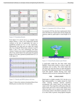
![In this paper, a method to achieve controllability and
stability of quad-copter at certain height is achieved
such that it is stationery with respect to the earth frame
of reference at certain height. Simulation platform
used are MATLAB®
and LabVIEW®
, while detail
study of quad-copter and propeller is conducted in
ANSYS-FLUENT®
. CAD models are modelled in
CATIA®
software. The algorithm is written by
manipulating the non-linear differential equations with
control theory. The algorithm written is verified by
visualizing results, animations and virtual reality
model to completely study the quad-copter behaviour
and response to inputs.
The algorithm is translated into equivalent C language
for Hardware testing. Microcontroller and sensor used
are Arduino Mega 2560 and 6-DoF Razor IMU only.
II. EQUATION OF MOTION
The governing equations for the control of quad-copter
are derived in this section. First of all, translational and
rotational dynamics of quadrotor are explained
followed by simplifications. Bold symbols are used to
denote three-dimensional vectors, while non-boldface
symbol are used for scalars in the paper.
Figure 2: (A) Dynamic model of a quad-copter with
four propellers in Earth frame of reference (B)
Propeller i producing fi thrust with 𝜔𝑖 rpm in z-
direction
A. Dynamics
A quad-copter is a UAV having four rotors and a mass
‘m’. The forces which act on a quadrotor are its weight
and the thrust f produced by four propellers in body
fixed direction z = (0, 0, 1). Similarly, four torques acts
on each propeller and a total drag torque acts on quad-
copter body. The rotation of the body fixed frame with
respect to some inertial frame is described by the
rotation matrix R which is discussed in detail.
Two coordinate systems are considered in Figure 4
[3]:
The inertial frame (E-frame)
The body-fixed frame (B-frame)
Figure 3: Quad-copter Frame of References
These are related through three rotations:
Roll: Rotation of φ around the x-axis;
Pitch: Rotation of θ around the y-axis;
Yaw: Rotation of ψ around the z-axis.
The following assumptions were made in this
approach:
The body-fixed frame origin and center of
mass (COM) of the body of the vehicle are
coincident.
The axes of the B-frame coincide with the
body principal axes of inertia.
Figure 4: Quad-copter configuration frame
system
Given equation describes the relation of Rotation
matrix with roll, pitch, yaw and quad-copter position
in earth frame.
R (,, ) R(x,) R(y,) R (z, ) ( 1 )
The main equation governing the quad-copter
dynamics is:
14
Fourth International Conference on Aerospace Science & Engineering (ICASE 2015) Proceedings](https://image.slidesharecdn.com/conferenceproceedingsicase2015final1-160918062150/85/Conference-proceedings-23-320.jpg)
![m𝐝̈ = 𝐑𝐳 ∑ fi +4
i=1 m𝐠 ( 2 )
Where d= (d1, d2, d3) are position vectors in inertial
frame of reference and g = (0, 0, -9.81) is gravitational
constant.
As quad-copter is a rigid body with four propellers.
The body inertia is expressed as diagonal matrix
IB
= [
Ixx
B
0 0
0 Iyy
B
0
0 0 Izz
B
] ( 3 )
The propeller is a symmetric body with respect to its
axis of rotation and can be considered as disc for
simplification. The propeller inertia is given by:
IP
= [
Ixx
P
0 0
0 Iyy
P
0
0 0 Izz
P
] ( 4 )
Due to symmetry of propeller Ixx
P
= Iyy
P
.
The angular velocity of a body can be governed using
the differential equation: [2]
τres = τB + ∑ τP + ⟦ωB
× ⟧(LB +4
i=1
∑ IP
ωB
+ ∑ LP
4
i=1
4
i=1 ) ( 5 )
Where τres is the resultant torque acting on quad-
copter body. τB is the body torque
τB = (Ixx
B
ṗ, Iyy
B
q̇, Izz
B
ṙ) ( 6 )
And τP is the torque produced by propeller.
τP = (0, 0, Izz
P
ωi̇ ) ( 7 )
B. Simplification of Assumptions
The effect of all the moments acting upon the body is
denoted by τres on the right hand side of equation (5).
These include moments due to propeller forces and
torques due to motors. The propeller forces are
assumed to act through the center of each propeller. It
is assumed that the center of propeller is at a horizontal
distance l from the body center of mass.
τres = [
(f2 − f4)l + τdx
(f3 − f1)l + τdy
τ1 + τ2 + τ3 + τ4 + τdz
] ( 8 )
With τd = (τdx
, τdy
, τdz
) is the drag torque. It has
been observed that propellers reaction torque has a
linear relation with the thrust force (with
proportionality constant of kτ and sign given by the
sense of rotation).
τi = (−1)i+1
κτfi ( 9 )
And thrust is related to rotor rpm as
fi = κfωi
2
( 10 )
Solving the above equation from 3 to 8 results in [2]
Ixx
B
ṗ = κf(w2
2
− w4
2)l − (Izz
T
− Ixx
T )qr − Izz
P
q(w1 +
w2 + w3 + w4), ( 11 )
Ixx
B
q̇ = κf(w3
2
− w1
2)l + (Izz
T
− Ixx
T )pr + Izz
P
p(w1 +
w2 + w3 + w4), ( 12 )
Izz
B
ṙ = −γr + κτκf(w1
2
− w2
2
+ w3
2
− w4
2
) ( 13 )
III. CONTROLLABILITY
These non-linear equations are linearized to compute
state space matrices A, B, C and D. An LQR controller
was designed with the cost value of 0.5 s2
rad-2
on the
angular rates, 10 on the deviation from the primary
axis, 0 on the extended motor states and 0.75 N-2
on
the inputs.
IV. EXPERIMENTAL PLATFORM
Computational Programming softwares employed
were MATLAB®
/ SIMULINK®
, LabVIEW®
,
ANSYS®
, Arduino IDE®
and CATIA®
.
CAD models of Quad-copter and equivalent propeller
were modelled in CATIA®
and were exported to
ANSYS-FLUENT®
where surface meshing and
computational fluid dynamics (CFD) was done to
study aerodynamic design such that fluid was passed
on to the quad-copter and propeller at different speeds
and direction to check its serviceability.
The propeller produced vibrations which were verified
from CFD analysis. These vibrations were catered
using prop-balancer system.
15
Fourth International Conference on Aerospace Science & Engineering (ICASE 2015) Proceedings](https://image.slidesharecdn.com/conferenceproceedingsicase2015final1-160918062150/85/Conference-proceedings-24-320.jpg)

![people which will help in making tasks easier and
more efficient. Developed mathematical model was
successfully implemented on hardware.
IX. ACKNOWLEDGMENT
This work has been made possible by the help of my
co-authors which include my project advisor and co-
advisor. This text has been rectified and proof read by
Undergraduate students M. Moghees Shahid and Ali
Mahmood. They are destined for great things.
This project has been sanctioned by College of
Aeronautical Engineering, NUST.
REFERENCES
[1] T. Luukkonen, "Modelling and control of
quad-copter," Independent research project
in applied mathematics, Espoo, 2011.
[2] M. W. Mueller and R. D'Andrea, "Stability
and control of a quadrocopter despite the
complete loss of one, two, or three
propellers," in Robotics and Automation
(ICRA), 2014 IEEE International Conference
on, 2014, pp. 45-52.
[3] I. Gaponov and A. Razinkova, "Quad-copter
design and implementation as a
multidisciplinary engineering course," in
Teaching, Assessment and Learning for
Engineering (TALE), 2012 IEEE
International Conference on, 2012, pp. H2B-
16-H2B-19.
[4] D. Hanafi, M. Qetkeaw, R. Ghazali, M. Than,
W. Utomo and R. Omar, 'Simple GUI
Wireless Controller of Quad-copter',
International Journal of Communications,
Network and System Sciences, vol. 06, no.
01, pp. 52-59, 2013
[5] Y. Cooper, R. Ganesh Ram, V. Kalaichelvi
and V. Bhatia, 'Stabilization and Control of
an Autonomous Quad-copter', AMM, vol.
666, pp. 161-165, 2014.
19
Fourth International Conference on Aerospace Science & Engineering (ICASE 2015) Proceedings](https://image.slidesharecdn.com/conferenceproceedingsicase2015final1-160918062150/85/Conference-proceedings-28-320.jpg)
![Detection of Fire Hotspots dealt by Emergency
First Responders in Rawalpindi using GIS
applications
Amna Butt and Sheikh Saeed Ahmad
Department of Environmental Sciences
Fatima Jinnah Women University
Rawalpindi, Pakistan
ambutt91@yahoo.com; drsaeed@fjwu.edu.pk
Abstract— During the past, need of efficient Emergency First
Response (EFR) for Rawalpindi, along with all the major cities of
Pakistan has increased tremendously. Therefore, there is a need
to develop an effective management strategy to improve the first
response services. Present study focused on the identification of
past and current service locations for fire incidences and
mapping these locations for hotspot identification. The incidence
data for past five years (2009-13) was collected and Hotspot and
Spatial Autocorrelation analyses were performed on the data to
detect the fire hotspots and their clustering patterns in the city.
The results revealed a slight shift in fire hotspots in 5 years and
also in the clustering pattern which changed from significantly
clustered (2009) to randomly distributed (2013). Hotspot and
spatial distribution maps were generated to indicate the fire
hotspots in the city. These maps can be helpful to prevent the
future incidents by allocating more service stations focusing these
areas for fire mitigation.
Index Terms— Hotspot Analysis, Fire, Kernel Density,
Emergency First Response (EFR), Spatial Autocorrelation
Analysis
I. INTRODUCTION
Coping with fire, caused either by natural or anthropogenic
factors is one of the challenges faced by the modern societies
[1]. Analyzing the city fire risk is therefore highly significant
for development of effective urban fire protection plan and
regulations and facilitates the coordinated development of
social economy [2].
Application of geostatistical tools of GIS can play a
significant role in improvement of local fire emergency
response [3] primarily by facilitating the visualization and
interpretation of nature and previously observed patterns of
such accidents [4][5]. Generating different fire risk maps on the
basis of geostatistical analysis is also imperative to develop
strategies focused on alleviating the future risk [6].
Numerous approaches based on GIS have been developed
and used over the past to provide geostatistical surveillance of
the precedent emergency patterns for development of several
models for fast and apt response delivery [7][8][9][10][11].
A. Study Area
The study area of the present research was Rawalpindi city
(Fig. 1). The city’s administrative boundaries consist of two
tehsils namely Rawal and Potohar tehsil. Currently five service
stations and two key points of Rescue 1122 (otherwise known
as Punjab emergency service) are providing emergency
response services (including fire brigade service) in different
areas of the city. The resources currently available to them for
providing Fire brigade service include 9 fire vehicles, 14
ambulances and personnel of 400 trained rescue providers.
However, no prior study has been conducted in the city focused
on surveillance of fire emergency response. Furthermore, the
existing management strategy for improvement of fire
emergency response is not very effective and no thought has
been given to incorporating GIS expertise in the department for
this purpose.
Fig. 1. Study Area map: Rawalpindi City
20
Fourth International Conference on Aerospace Science & Engineering (ICASE 2015) Proceedings](https://image.slidesharecdn.com/conferenceproceedingsicase2015final1-160918062150/85/Conference-proceedings-29-320.jpg)
![Therefore, the primary objective of the present research is
to provide a GIS based surveillance system for the Fire
incidents of the past in order to determine the recurrent service
locations for focusing the future response. The study can
therefore be considered as a baseline for future improvement in
the quality and efficiency of fire emergency responses in
Rawalpindi city.
II. MATERIALS AND METHODS
The research methodology that was applied to obtain the
results primarily consisted of four main steps incorporating
data collection, processing, analyzing and visualizing the
results (Fig.1).
Fig. 2. Flowchart of main steps followed in methodology
B. Data Collection and Processing
The data collected for the purpose of this study was divided
into two categories namely Primary and Secondary data. The
main data obtained for the purpose of the study was secondary
data acquired from the headquarters of Rescue 1122,
Rawalpindi in form of caller and victim directory. This data
was collected on unit level i.e. data from all the emergency
units of 1122 at work in Rawalpindi city was acquired,
compiled and then processed for segregation of Fire cases.
Primary data was then collected on the basis of segregated fire
incidents. This data comprised the GPS readings of incident
locations obtained via handheld Oregon 650 GPS for the
reported fire cases.
Both primary and secondary data was processed in
Microsoft excel and then loaded to ArcGIS 10.2 for further
processing and analyzing.
C. Geostatistical Analysis of data
The data was geostatistically analyzed in ArcGIS 10.2
environment for determination of spatial clustering and
identification of hotspots. The geostatistical analysis performed
for this purpose included Global Moran’s I test (Spatial
autocorrelation analysis) and Hotspot Analysis (Getis-Ord
Gi*).
1) Global Moran’s I statistics
Global Moran’s I statistic gives an indication of any
existing correlation among spatial observations and delineates
the characteristics of the global pattern. The pattern maybe
random, dispersed or clustered depending on the spatial
association present in the data [12][13]. For the purpose of
present study spatial autocorrelation among the fire incidents
was calculated on yearly basis by employing different
threshold limits ranging from 500-2000 meters. The range used
for determination of correlation was -1 to 1 and Z-score value
was calculated to assess the statistical significance of the
observed clustering (based on correlation) for each year. The
highest correlation values were then recorded for each year and
subsequently were employed for hotspot identification.
2) Hotspot Analysis: Getis-Ord Gi*
Fire hotspots were identified based on the Getis-Ord Gi*
statistics. For this purpose, the conceptualization of spatial
relationship among different datasets was done by opting
“Zone of indifference”. The threshold limit was set on the basis
of spatial autocorrelation outcomes for each year (exhibiting
highest Z-score value). Thereafter, the identified hotspots for
Fire cases were interpolated using “Inverse Distance
Weighted” or “IDW” for better visualization of results and
hotspot maps for each year were generated.
III. RESULTS
The emergency callout data on building fires, bursting of
gas pipes, cylinder blasts, and gas leakages was cataloged in
the category of Fire emergencies. Different geostatistical
analyses were then performed to determine the pattern of
emergency cases for the study duration. The reported incidence
of FE cases for the time period of 2009-2013 were 671. Out of
which, 583 (86.9%) were males and 88 (13.1%) females. 15%
of the total fire incidents (102 cases) were reported in 2009 and
37% (247 cases), the highest incidence, in 2010. After 2010 the
incidence rate declined progressively from 24% (163 cases) in
2011 to 10% (66 cases) in 2012 and subsequently rose to 14%
(93 cases) in 2013 (Fig. 3).
Fig. 3. Percentage Contribution of Fire Incidents in Rawalpindi during 2009-
2013
The possible spatial autocorrelation of Fire cases estimated
by Moran’s I statistics revealed significant spatial clustering for
the years 2009 and 2011, whereas 2010 showed mild
clustering. 2012 and 2013 on the other hand showed random
patterns. Moran’s I and G-statistic values (Z-score) for all the
years, given in Table 1 disclosed that 2009 had highest (20.01)
while 2013 had lowest (1.10) Z-score.
21
Fourth International Conference on Aerospace Science & Engineering (ICASE 2015) Proceedings](https://image.slidesharecdn.com/conferenceproceedingsicase2015final1-160918062150/85/Conference-proceedings-30-320.jpg)
![Fig. 5. Spatial Distribution pattern of Fire incidents in Rawalpindi for study
duration
IV. DISCUSSION
In order to facilitate the efficient management of fire
emergencies in an area, improvement of existing response
systems is of high significance [14]. This can be ensured by the
providing surveillance for past occurrences and understanding
of recurring patterns.
Significant Fire hotspots were manifested in both urban and
rural areas of the city and were mainly contained in Northern
portion of the study area. These were the areas having high rise
buildings, gas stations, commercial areas, suburban areas,
highways and residential areas (with heavy load shedding of
gas). As these hotspots were estimated not only for household,
commercial and secondary fires but vehicular fires as well,
various roads were also identified as hotspots. Mostly the Fire
emergencies were observed on the roads that are used by heavy
vehicles as they are more prone to overturning and catching
fire. Corcoran et al. [11] also analyzed the spatial patterns of
fire by employing GIS and obtained similar results. Rao [15]
also reported similar findings and additionally said that the
reason for Fire incidents in the city is exposed and jumbled
cable wires made of substandard material.
However, the results of the study indicated a significant
decline in the intensity of cases for the duration of the study
(Fig. 3). This declining incidence gave an account of lack of
confidence in general public to refer to firefighting
organizations and attempting to solve the matter themselves.
However the accounted figures do not represent the total
number of cases observed in the city, just the incidence that
was dealt by Rescue 1122. Other organizations at work in the
city for fire control and management include Rawalpindi Fire
Brigade Center and Qureshi Fire Control Services.
Akhter [16] explicated the reasons behind the lack of
confidence among public. The study reasoned that there is
disparity in implementation of fire safety standards in the city
as well as very little coordination among different departments
such as traffic, police and fire fighting units. This lack of
coordination along with unavailability of Incident Command
System (ICS) often translates to poor emergency response
despite good skills and training. Dawn [17] conversely reported
that local fire brigade services lack in performance due to
insufficient professional training, availability of resources,
planning and research (both pre and post fire) and nonexistence
of any fire services act for the city. All these factors, along with
lack of awareness among general public regarding fire fighting
profession has a negative impact on fire emergency response.
Hence, for improvement of future fire emergency response,
it is need of hour to understand the previous and existing
patterns, risk factors and causative agents; and ensure effective
enforcement of building and fire safety laws [18].
V. CONCLUSION AND RECOMMENDATIONS
Present study focused on providing a geostatistical
surveillance approach for ensuring future fire safety by
improving the response quality and apt resource allocation for
high risk areas. Based on the outcomes of the research, it is
concluded that there is both spatial and temporal variation in
the occurrence of Fire incidents in the study area. Most of the
Fire hotspots however were located in the Northern portion of
the study area incorporating both urban and rural areas of the
study indicating the need to shift the focus of fire service in this
region of the study area. The study further concludes that there
is a need of incorporation of GIS based surveillance system in
the rescue department to direct the response from the service
stations in a timely manner.
Therefore, the study recommends generating awareness
among people regarding fire hazard and the factors associated
with it, incorporation of GIS expertise in emergency
departments, promotion of GPS enabled cell phones in dispatch
units and fire vehicles, high level of collaboration among
different departments working in the city for fire services
provision to avoid service duplication and publication of GIS
based maps and models designed for response improvement.
ACKNOWLEDGMENT
We are endepted to the department of Rescue 1122,
Rawalpindi for providing the data regarding fire emergencies
and cooperating with us throughout this research.
REFERENCES
[1] M. I. Channa, and K. M. Ahmed, “Emergency Response
Communications and Associated Security Challenges,” Int. J.
Net. Sec. and its Appli., vol. 2 (4), pp. 179, 2012.
23
Fourth International Conference on Aerospace Science & Engineering (ICASE 2015) Proceedings](https://image.slidesharecdn.com/conferenceproceedingsicase2015final1-160918062150/85/Conference-proceedings-32-320.jpg)
![[2] W. Aiyou, S. Shiliang, L. Runqiu, T. Deming, and T. Xiafang,
“City Fire Risk Analysis based on Coupling Fault Tree Method
and Triangle Fuzzy Theory,” Proc. Engg., vol. 84, pp. 204-212,
2014.
[3] Environmental Systems Research Institute (ESRI), “Improving
Emergency Planning and Response with Geographic
Information Systems,” Redlands, New York: ESRI. Retrieved
from http://www.esri.com/library/whitepapers/pdfs/emergency-
planning-response.pdf, 2005.
[4] S. Erdogan, I. Yilmaz, T. Baybura, and M. Gullu,
“Geographical information systems aided traffic accident
system case study: city of Afyonkarahisar,” Accid. Anal. and
Prev., vol. 40, pp. 174-181, 2008.
[5] M. Kwan, and J. Lee, “Emergency response after 9/11: the
potential of real-time 3D GIS for quick emergency response in
micro-spatial environments,” Comp., Env. and Urban Sys., vol.
29, pp. 93-113, 2005.
[6] C. Yan-yan, L. Dong, and Z. Hui, “Multi-factor Risk Analysis
in a Building Fire by Two Step Cluster,” Proc. Engg., vol. 11,
pp. 658-665, 2011.
[7] M. H. Hussain, M. P. Ward, M. Body, A. Al-Rawahi, A. A.
Wadir, S. Al-Habsi, M. Saqib, M. S. Ahmed, and M. G.
Almaawali, “Spatio-temporal pattern of sylvatic rabies in the
Sultanate of Oman, 2006–2010,” Prev. Vet. Med., vol. 110, pp.
281-289, 2013.
[8] T. Ruya, M. Ning, L. Qianqian, and L. Yijun, “The Evolution
and Application of Network Analysis Methods,” IEEE Int.
Conf. on Sys., Man, and Cyber., pp.2197-2201, 2013, DOI
10.1109/SMC.2013.376.
[9] D. Dai, “Identifying clusters and risk factors of injuries in
pedestrian–vehicle crashes in a GIS environment,” J. Trans.
Geo., vol. 24, pp. 206-214, 2012.
[10] A. Spoerri, M. Egger, and E.V. Elm, “Mortality from road
traffic accidents in Switzerland: Longitudinal and spatial
analyses,” Accid. Anal. and Prev., vol. 43, pp. 40-48, 2011.
[11] J. Corcoran, G. Higgs, C. Brunsdon, A. Ware, and P. Norman,
“The use of spatial analytical techniques to explore patterns of
fire incidence: A South Wales case study,” Comp., Env. and
Urban Sys., vol. 31, pp. 623-647, 2007.
[12] B.N. Boots, and A. Getis, Point Pattern Analysis Newbury
Park. Newbury Park, CA, USA: Sage Publications, 1998.
[13] L. Fang, L. Yan, S. Liang, S. J. D. Vlas, D. Feng, X. Han, W.
Zhao, B. Xu, L. Bian, H. Yang, P. Gong, J. H. Richardus, and
W. Cao, “Spatial analysis of hemorrhagic fever with renal
syndrome in China,” BMC Infect. Dis., vol. 6, pp. 77-88, 2006.
[14] S.R. Morgan, A. M. Chang, M. Alqatari, and J. M. Pines,
“Non–Emergency Department Interventions to Reduce ED
Utilization: A Systematic Review,” Acad. Emer. Med., vol. 20,
pp. 969-985, 2013.
[15] S. Rao, “Rescue 1122 management plan finalized,” The
Nation. Retrieved from http://nation.com.pk/karachi/06-Jan-
2010/Rescue-1122-management-plan-finalised, 2010.
[16] S. Akhter, “Firefighters’ view on Improving Fire Emergency
Response: A Case Study of Rawalpindi,” Int. J. Hum. and Soc.
Sci., vol. 4(1), pp. 143-149, 2014.
[17] Dawn, “Pindi fire brigade squad runs out of steam,” Dawn.
Retrieved from http://www.dawn.com/news/90148/rawalpindi-
pindi-fire-brigade-squad-runs-out-of-steam, 2003.
[18] Pakistan Observer, “1122 Rawalpindi Rescued 1883 Emergency
Victims,” Pakistan Observer. Retrieved from
http://pakobserver.net/detailnews.asp?id=251475, 2014.
24
Fourth International Conference on Aerospace Science & Engineering (ICASE 2015) Proceedings](https://image.slidesharecdn.com/conferenceproceedingsicase2015final1-160918062150/85/Conference-proceedings-33-320.jpg)
![Prospects of Airborne Wind Energy Systems
in Pakistan
Z. H. Khan
Dept. of Electrical Engineering
Riphah International University
Islamabad, Pakistan
zeeshan.hameed@riphah.edu.pk
Sohaib Khan
Dept. of Aerospace Engineering
Institute of Space Technology
Islamabad, Pakistan
sohaibkham786@gmail.com
Arsalan Khan
Dept. of Control and Simulation
CESAT
Islamabad, Pakistan
arsalan1@mail.nwpu.edu.cn
Abstract— High altitude wind energy is considered as a high
efficiency, low cost solution to sustainable energy solutions
worldwide today due to highly flexible and adaptive designs of
powered kites. Pakistan is facing energy crisis since years due to
inefficient electrical transmission network, increased demand of
electricity, lack of resource planning and increased cost for
furnace oil which can be used to generate electricity. As a clean
energy source, conventional wind energy is a preferable choice
but it has few disadvantages due to large initial investments
involved and dangers to environment due to rotating machinery
which can result in bird hit and on the other hand, generating
acoustic noise which affect populations of people living nearby.
In response to these issues, high altitude energy is found to be
free from many such problems as found with conventional wind
energy systems. It is found suitable specially for addressing
essential energy needs of off-grid consumers for water pumping,
drilling, refrigeration of vaccines and life-saving medicines and
powering up far-off residential sites e.g. communities living off-
grid at Alaska’s northern region having minimal solar energy
during the long winter season when energy demand is greatest
for heating purposes. In this paper, we propose a UAV design
which can possibly be used as an airborne wind energy system
for electricity generation.
Keywords—Altitude wind; renewable energy; powered kites;
wind energy conversion system; distributed energy
I. INTRODUCTION
Energy production for a world’s economy is directly linked
with GDP growth. Renewable energy solutions are a preferable
choice to address the energy demands world-wide due to
environment friendly green energy technology. It has been
estimated that till 2050, 40% of the world energy requirements
will be meet by renewable energy including solar (photo
voltaic (PV) and thermal), wind, bio-mass, bio-fuel etc. [1].
Among various technologies, wind energy is preferred due to
continuous production of electricity (as long as wind is present
as prime mover) as well as high production rate with lesser
requirement of installation area as compared to solar energy
[2]. However, a detailed analysis of wind availability and on-
site surveying is mandatory for an optimal production of
energy throughout the year. The conventional wind energy
conversion systems (WECS) are popular only in those areas
where sufficient wind is available i.e. in the range of 5-8 m/s2
.
This limitation greatly affects the utilization of WECS as an
effective resource of energy as usually far off areas near sea-
shores or mountains fulfills the required energy density criteria
for feasible investments. Also, long way cabling for
transmission of this energy to grid also results in additional
cost and line losses [3]. Social activists and NGOs raise voices
and show their grievances against environmental impact of
these wind farms due to ever increasing bird accidents as of
result of collision with fast moving blade tips.
Fig 1. Airborne energy production connected to grid
This paper describes some key design features of an
airborne wind energy system (AWES) e.g. a large kite which is
flown in air while maintaining its connection with a generator
kept at ground level by a suitable rotating mechanism such as
cable drum which is linked via tether. The aerodynamic forces
acting on the kite causes traction in the cable drum which is in
turn converted into electrical power by the generator as shown
in Fig 1. The obvious advantages of shifting the heavy
mechanical components on ground result in simple design and
maximum power optimization. Due to the fact that the flying
kite operates in periodic cycles alternating between ―traction
phase‖ and ―reel-in phase‖ of the tether, the electrical power
produced is not continuous rather intermittent which is not
25
Fourth International Conference on Aerospace Science & Engineering (ICASE 2015) Proceedings](https://image.slidesharecdn.com/conferenceproceedingsicase2015final1-160918062150/85/Conference-proceedings-34-320.jpg)
![suitable for on-grid connection where continuous power is
required. However, a continuous power generation system can
be designed either by using multiple, individually controlled
kites or a battery system for buffering the power generation
across the cycles. This solution is guaranteed to generate
higher power with lower cost as compared to conventional
wind energy conversion system (WECS) due to availability of
faster wind speeds at high altitude.
Fig 2. KGS for generating electricity on-board ship
II. HIGH ALTITUDE WIND ENERGY POTENTIAL
Wind energy is a renewable resource which is not only
cheap but also readily available in most parts of the world.
Wind is discontinuous source of energy and the conventional
WECS provides uneven power supply when connected to the
grid. On the other hand, if altitude is raised, a lot more energy
is available as compared to that blowing at 50-200 m above
ground. It has been estimated that the magnitude of wind
energy above 1000 m is twice as much as found at lower
altitudes. In addition, at an altitude of 800 m above ground,
wind power density is sufficiently available to be used for
altitude energy generation all over the globe [4]. As a rule of
thumb, it has been found that a five-fold cost saving with twice
capacity increase can be achieved in shifting technology from
WECS to AWES [5].
III. ADVANTAGES OF AWES OVER WECS
A. Impact on Environment
The airborne wind energy systems have fewer effects on
environment as compared to WECS. The fast moving blades of
classical wind mills injures many birds flying in close
proximity. On the other hand, AWES has no dangerous edges
which can kill birds [6].
B. Cost comparison
Using AWES instead of WECS, an advantage of more than
90% material savings is guaranteed. This is because large
structures require more and more material to with stand heavy
loads due to wind and the rotating machinery [7]. Many tones
of weight loaded on large erected structures comprises of rotor
blades connected to a hub which drives the generator.
Moreover, the maintenance of WECS is also an issue which
requires access to the system, long down times in case of fault
and danger to the life of technician all adding up the cost
compared to AWES where generator and accessories are
installed on ground [8].
C. Mobility of the power station
In comparison with WECS, the airborne energy converter
can be moved anywhere. Example include rural areas, Coastal
belt, Desert, etc. However, if flying at higher altitudes, caution
must be paid to operate AWES in no-fly zones (NFZ) to avoid
any danger for civil aviation.
D. Efficiency
The advantage of increasing altitude as in the case of
AWES is to get more capacity due to persistent wind as
compared to turbulence due to buildings and infrastructure at
WECS heights [9].
Fig 3. Buoyant Airborne Turbine (BAT) for stand-alone energy generation in
Alaska [10]
IV. CLASSIFICATION OF AWES
The airborne wind energy systems are classified based on
their designs, grid connectivity and aerodynamics e.g. heavier
than or lighter than air configuration. Some types are indicated
as follows:
1) Flying tethered airplane and kite
In this type of AWES, a tethered kite or airplane flies in
circular or Lissajous shaped orbit to produce electricity via
traction force applied on a generator on ground or ship as
shown in Fig 2. The kite generator system (KGS) is one of the
most commonly used system due to its simplest design and
easy control system [11].
2) Multiple wing system
This type of altitude wind system has multiple wings to
generate electrical energy. A laddermill is an example of such
system [12]. Multiple wings allow scalability of the concept in
order to generate more energy.
3) Lighter than air systems
These systems are lighter than air and have an on-board
generator to produce electricity as shown in Fig 3. Such
systems are supported by a lighter than air filled balloon to
reach at 100m or above heights where enough wind is
available to drive the generator [13]. Such systems are more
suitable for areas of the world where sunlight is not available
throughout the year.
26
Fourth International Conference on Aerospace Science & Engineering (ICASE 2015) Proceedings](https://image.slidesharecdn.com/conferenceproceedingsicase2015final1-160918062150/85/Conference-proceedings-35-320.jpg)
![4) Rotor hover craft systems
These systems hover in air via rotating propellers.
Quadrotor type hovercrafts are popular which have the ease of
vertical take-off and landing operations [14]. Due to on-board
generators, the airborne system is heavier as compared to the
crosswind kite generator in which has the heavy machinery on
ground.
V. FLYING WING GENERATOR SYSTEM DESIGN
In order to visualize a practical system, we can use a flying
wing generator (FWG) for our case study. Our goal is to
evaluate optimal design parameters which can be used to
generate maximum wind at different altitudes. By using a
strong flexible tether, energy kites can reach higher altitudes of
100 to 400 meters). This can save up to 90% of the materials of
WECS used conventionally, resulting in reduced per unit
energy cost. As, these systems are more aerodynamic and can
access higher energy density due to stronger winds, each EKS
can generate 50% more energy than their conventional
counterparts [15].
A. Aerodynamics
The wind energy that can be converted to electricity is
given as:
2
3
27
2
D
L
Lw
C
C
CAvP (1)
The relation provides some significant information about
some key design parameters. Equation 1 states that in order to
increase the power, the key parameters to increase include the
wind speed, gliding ration (L/D), the lift coefficient and the
wing surface. As a comparison, energy kites have lower L/D,
price and weight as compared to flying wing. In theory, about
60 kW can be produced per sq. meter of flying kite generator
system. The CFD model is shown in Fig 4.
(a) Side View (b) Top View (c) Front View
Fig 4. FlyPG simulation for aerodynamic analysis
In order to analyze the aerodynamic performance of our
benchmark system FlyPG, different flight conditions are used
for Aerodata generation. The aircraft wing is taken as NACA-
W-4-4410 which has a span of 4 meters, Sref equal to 1.5 m2
,
Cbar = 0.38 m, Root chord = 0.35 m, Tip chord = 0.15 m. For
the vertical tail design, NACA-V-4-0010 is selected with Root
chord = 0.25m and Tip Chord = 0.1 m. The horizontal tail
design is NACA-H-4-0010 based with root chord = 0.25 m
and Tip chord = 0.1 m.
The flight test condition is selected as Mach 0.05 at an
altitude of 200 meters above ground level. Then the angle of
attack (α) in degrees is varied from 0 to 5 degrees, while Xcg
of 0.9 meter is assumed. The aero-data is plotted in Fig 5 as a
function of angle of attack. It is important to take into account
at least 10% drag increase due to tether connecting the kite
with the ground generator.
Fig 5. Aerodata plots for FlyPG @ Mach = 0.05
B. Control and Autopilot
Modern design of FWGs incorporates automatic take
off/landing and flight for robust operation under varying
environmental conditions [16]. A coordinated control
mechanism is also devised by few manufacturers where
communication between the Kite/airplane controller and main
controller at the ground station occurs to track the given
trajectory [17].
Generally, a multi-objective loop controls the dynamics of
the system in flight. First of all, an optimal track point on
circular or Lissajous trajectory needs to be calculated and
tracked during flight [18]. In most cases a navigation loop
forms the outer one which controls the bearing of the flying
system, while an inner attitude controller controls the roll, pitch
and yaw angle as well as respective rates in order to achieve
the required bearing.
Fig 6. A generalized 2-loop control structure for Flying wing/ Energy Kite
As shown in Fig 6, an outer loop controls the bearing
(ρcom) of the flying wing. The error between the commanded
and measured bearing drives the attitude controller in order to
generate roll, pitch and yaw commands for the flying wing
until it reaches the desired navigational coordinates. In this
27
Fourth International Conference on Aerospace Science & Engineering (ICASE 2015) Proceedings](https://image.slidesharecdn.com/conferenceproceedingsicase2015final1-160918062150/85/Conference-proceedings-36-320.jpg)
![control loop, however, the cross track controller is not
included which is necessary to keep the flying wing on the
desired trajectory by removing the off-track distance [19]. In
practice, stable and robust control is required for fast tracking.
C. Mechanical Subsystem
The mechanical part of a FWG includes wing design after
aero-foil selection. The control actuators (motors) also need
positioning and the embedded controller is designed w.r.t
nominal torque load as well as keeping its maximum limit as
per maximum torque demand. The selection of tether and its
linkage with the ground generator is also important [20].
However, the drag added by the tether length must be added in
the aerodynamic drag analysis for the autonomous controller
design [21].
D. Electrical Subsystem
The power generation system usually comprises of a
permanent magnet synchronous machine (PMSM) which acts
as a generator [22]. In general, the AWECS can function either
as stand-alone (off-grid) or on-grid. However, an obvious
problem for grid based operation requires an additional cost of
storage system or operating multiple systems at the same time
so that the pumping cycle of one kite is out of phase as
compared to the pumping cycle of the other kites [23]. Thus, at
the instant one kite is relaxing; the other will be supplying
energy to the grid. However, this strategy complicates the
design of the AWECS.
E. Communication Subsystem
The communication system is required in order to control
the system and for data acquisition. Wireless networks are a
preferred choice in order to reduce weight and cost of the
airborne system [24, 25]. A suitable network protocol is chosen
as required depending upon the range of communication
required. Ground based sensors and controllers send necessary
data to the air segment. Security features of the communication
protocol must be operational for robust and uninterrupted
control of the flying system [26].
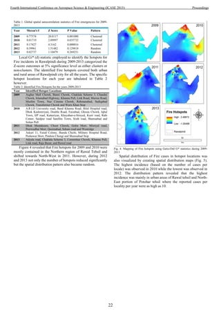
2000 2003 2006 2009 2012 2015 2018
0
50
100
150
200
250
300
350
400
450
500
ElectricalEnergy(MW)
Time
Fig 7. WECS for energy generation and forecast in Pakistan
VI. ENERGY NEEDS IN PAKISTAN
Pakistan is the 6th
largest country of the world with a total
estimated population of 175 million people. However, 24%
population lives below the poverty line in the country. As per
the economic survey, it is among those countries of the world
which have lowest per capita energy consumption. The
installed electricity generation capacity is around 22,500 MW.
While the current available power is 17,000 MW, the peak
demand raises up to 22,000 MW in summer resulting in a
shortfall of 5000 MW.
The economic advisory council of Ministry of Finance
(Govt of Pakistan) foresees an increase in energy demand up to
122.46 M.MTOE in 2022 [27]. In order to satisfy this demand,
at least 12% of this energy is planned to be obtained from
renewable resources in order to relax the huge demand of
furnace oil exports from 30% at present to 20% in 2022 [28].
Table 1 describes the energy demand and forecast which shows
that a total of 122.46 M.MTOE demand is expected in 2022
out of which 14.70 M.MTOE will be obtained from renewable
energy. Looking at the rise in using wind energy as the
renewable source in Pakistan as shown in Fig. 7, it is
emphasized that Altitude wind projects should also be
commenced in the country as a future energy resource
especially for people living in off-grid areas of Pakistan.
In order to enhance sustainable energy trend, Government
has exempted renewable energy equipment from income
tax/withholding tax and sales tax [29]. Also, import duties have
been waived off for import of such machinery and tools to be
used to develop sustainable energy solutions. Thus, already a
favorable environment is available for foreign investors to
come and finance green energy solutions. Fig. 7 shows a
potential rise of WECS usage as a renewable energy source.
However, the feasibility is only limited to areas where
sufficient wind is present. These areas include the coastal belt
near Karachi (Sindh province), Kati-Bander, Makran and
Jhampir in Balochistan [30, 31].
Figure 8 Map of Pakistan's national grid [32]
As noted from the title of the paper, our target is to address
the energy demands of remote areas of the country far-off from
28
Fourth International Conference on Aerospace Science & Engineering (ICASE 2015) Proceedings](https://image.slidesharecdn.com/conferenceproceedingsicase2015final1-160918062150/85/Conference-proceedings-37-320.jpg)
![the national grid. Fig. 8 describes the map of Pakistan’s
national grid which shows large areas of Balochistan not
covered by it. This is because of the low population density in
this province as well as poverty due to which it is not feasible
to extend the grid in these areas. Villages in these areas can be
powered up by renewable energy resources by spending less
money and requiring only maintenance cost in the long run
[33].
TABLE I. PAKISTAN ENERGY DEMAND FORECAST [27]
Resource
Energy Demand (M.MTOE)
1992 2008 2022
Oil 11.53 19.18 24.49
Gas Indigenous 11.68 29.88 25.72
Gas Import - - 8.57
Hydel 4.49 6.86 24.49
Coal 2.10 5.79 18.37
LPG 0.15 0.44 2.45
Nuclear - 0.75 3.67
Renewables - - 14.70
Total 29.94 62.90 122.46
Most common uses there require lightening solution, water
pumping for drinkable water supply and also to operate tube-
wells for agriculture use etc. These applications require
lightweight, low-cost, minimum energy storage solutions.
These demands can be fulfilled by using AWES whereby the
intermittent energy produced during reel out phase could be
used directly.
VII. CONCLUSION
In this paper, an overview of altitude wind technology is
discussed and a preliminary analysis is done for the suitability
to address the needs of renewable energy in developing
countries with budget constraints. A flying wing generator
design is also presented with some initial CFD simulation
results. As the model of FlyPG is now generated, the next step
is to design a prototype system and to demonstrate the energy
output by flying it. Moreover, as the energy needs in the
country are growing, it is high time to invest in such aerospace
technologies to obtain optimal designs resulting in maximum
electrical output with light weight flying systems.
REFERENCES
[1] M. A. Sheikh, "Energy and renewable energy scenario of Pakistan,"
Renewable and Sustainable Energy Reviews, vol. 14, pp. 354-363, 2010.
[2] J. I. Lewis and R. H. Wiser, "Fostering a renewable energy technology
industry: An international comparison of wind industry policy support
mechanisms," Energy Policy, vol. 35, pp. 1844-1857, 2007.
[3] G. Kingsley, "Wind energy production using kites and ground mounted
power generators," ed: Google Patents, 2003.
[4] M. lppolito, "Altitude Wind Energy Generation (Information Dossier),"
KiteGen Research, Italy2007.
[5] L. Goldstein, "Theoretical analysis of an airborne wind energy
conversion system with a ground generator and fast motion transfer,"
Energy, vol. 55, pp. 987-995, 2013.
[6] M. I. Blanco, "The economics of wind energy," Renewable and
Sustainable Energy Reviews, vol. 13, pp. 1372-1382, 2009.
[7] B. W. Roberts, "Cost and Security of Electricity Generated by High
Altitude Winds," Altitude Energy2012.
[8] M. Brooks, "To make the most of wind power, go fly a kite," New
Scientist, May, vol. 5, 2008.
[9] R. van der Vlugt, J. Peschel, and R. Schmehl, "Design and Experimental
Characterization of a Pumping Kite Power System," in Airborne Wind
Energy, ed: Springer, 2014, pp. 403-425.
[10] C. Vermillion, B. Glass, and A. Rein, "Lighter-Than-Air Wind Energy
Systems," in Airborne Wind Energy, ed: Springer, 2013, pp. 501-514.
[11] M. Ippolito, "Kite Wind Generator," ed, 2006.
[12] B. Lansdorp and P. Williams, "The laddermill-innovative wind energy
from high altitudes in holland and australia," in Wind Power, 2006.
[13] C. Vermillion, T. Grunnagle, and I. Kolmanovsky, "Modeling and
control design for a prototype lighter-than-air wind energy system," in
American Control Conference (ACC), 2012, 2012, pp. 5813-5818.
[14] G. Mortimer. (2014, 29th October). Multicopter based wind turbines.
Available: http://www.suasnews.com/2010/10/2464/multicopter-based-
wind-turbines/
[15] MAKANI. (2013, 20th November). Advanced Wind Energy "ENERGY
KITES". Available: http://www.google.com/makani/
[16] M. Canale, L. Fagiano, and M. Milanese, "High altitude wind energy
generation using controlled power kites," Control Systems Technology,
IEEE Transactions on, vol. 18, pp. 279-293, 2010.
[17] M. Canale, L. Fagiano, M. Ippolito, and M. Milanese, "Control of
tethered airfoils for a new class of wind energy generator," in Decision
and Control, 2006 45th IEEE Conference on, 2006, pp. 4020-4026.
[18] R. Lozano Jr, M. Alamir, J. Dumon, and A. Hably, "Control of a wind
power system based on a tethered wing," Proceedings of second
EGNCA 2012, 2012.
[19] C. Vermillion, B. Glass, and B. Szalai, "Development and Full-Scale
Experimental Validation of a Rapid Prototyping Environment for Plant
and Control Design of Airborne Wind Energy Systems," in ASME 2014
Dynamic Systems and Control Conference, 2014, pp. V002T18A001-
V002T18A001.
[20] R. Marissen, "Dyneema high strength, high modulus polyethylene
fiber," vol. CIS YA100, Dyneema, Ed., ed: Royal DSM N.V., 2008, p.
4.
[21] L. Fagiano, "Control of tethered airfoils for high–altitude wind energy
generation," Politecnico di Torino, 2009.
[22] M. Ahmed, A. Hably, and S. Bacha, "Grid-connected kite generator
system: Electrical variables control with mppt," in IECON 2011-37th
Annual Conference on IEEE Industrial Electronics Society, 2011, pp.
3152-3157.
[23] P. Williams, B. Lansdorp, and W. Ockesl, "Optimal crosswind towing
and power generation with tethered kites," Journal of guidance, control,
and dynamics, vol. 31, pp. 81-93, 2008.
[24] Z. H. Khan, D. G. Catalot, and J.-M. Thiriet, "Hierarchical wireless
network architecture for distributed applications," in Wireless and
Mobile Communications, 2009. ICWMC'09. Fifth International
Conference on, 2009, pp. 70-75.
[25] Z. H. Khan, J. M. Thiriet, and D. Genon-Catalot, "Wireless network
architecture for diagnosis and monitoring applications," in Consumer
Communications and Networking Conference, 2009. CCNC 2009. 6th
IEEE, 2009, pp. 1-2.
[26] J. Wang, M. Shahidehpour, and Z. Li, "Security-constrained unit
commitment with volatile wind power generation," Power Systems,
IEEE Transactions on, vol. 23, pp. 1319-1327, 2008.
[27] E. A. Council, "Integrated Energy Plan (2009-2022), Report of the
Energy Expert Group " Ministry of Finance2009.
[28] M. A. Khan and U. Ahmad, "Energy demand in Pakistan: a disaggregate
analysis," The Pakistan Development Review, pp. 437-455, 2008.
29
Fourth International Conference on Aerospace Science & Engineering (ICASE 2015) Proceedings](https://image.slidesharecdn.com/conferenceproceedingsicase2015final1-160918062150/85/Conference-proceedings-38-320.jpg)
![[29] A. W. Bhutto and S. Karim, "Energy-poverty alleviation in Pakistan
through use of indigenous energy resources," Energy for Sustainable
Development, vol. 11, pp. 58-67, 2007.
[30] M. Hussain, S. Abbas, M. Ansari, A. Zaffar, and B. Jan, "Wind Speed
Analysis of Some Coastal Areas near Karachi," Pakistan Academy of
Sciences, 2012.
[31] I. Ullah, Q.-u.-Z. Chaudhry, and A. J. Chipperfield, "An evaluation of
wind energy potential at Kati Bandar, Pakistan," Renewable and
Sustainable Energy Reviews, vol. 14, pp. 856-861, 2010.
[32] GENI. (2012). Global Energy Network Institute. Available:
http://www.geni.org/globalenergy/library/national_energy_grid/pakistan
/pakistaninationalelectricitygrid.shtml
[33] M. Amer and T. U. Daim, "Selection of renewable energy technologies
for a developing county: a case of Pakistan," Energy for Sustainable
Development, vol. 15, pp. 420-435, 2011.
30
Fourth International Conference on Aerospace Science & Engineering (ICASE 2015) Proceedings](https://image.slidesharecdn.com/conferenceproceedingsicase2015final1-160918062150/85/Conference-proceedings-39-320.jpg)


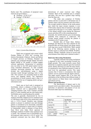
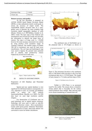
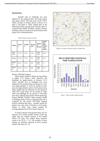

![Figure 10. Pond Capacity
IV. CONCLUSIONS
Proposed water reservoir in rain-fed area would have
a significant favourable effect on intended
beneficiaries. In addition to direct benefits from
changes in agricultural landscape there will be
indirect benefits for the relevant households from
appreciation of their land values, creation of
employment opportunities / reduction in
underemployment and incidence of poverty,
groundwater recharge and improvement in drinking
water supply.
However to ensure realization of anticipated benefits
of this dam, it will be essential to undertake capacity
building of target beneficiaries in terms of financial
resources and knowledge / technology acquisition
regarding high value agricultural commodities /
enterprises.
In fact, the dam site will improve overall water
availability, soil properties, land use and consequent
socio economic status of the inhabitants and thus
enhancing regional development.
Minor possible health considerations will be
countered through inhabitant sensitization and urging
concerned authorities ensuring better healthcare and
regional safeguard measures. The project is thus
highly recommended as Sustainable Development
and could also be replicated to other parts of the
country.
REFERENCES
[1] Minár, J., et al. "Geomorphological information system: idea
and options for practical implementation." Geograficky
Casopis Slovenskej Akademie, Vied57(3), pp. 247, 2005.
[2] Rabus, B., et al. "The shuttle radar topography mission—a
new class of digital elevation models acquired by
spaceborne radar." ISPRS J. Photogrammetry and Remote
Sensing, vol. 57(4), pp. 241-262, 2003.
[3] Reuter, H. I., et al. "An evaluation of void‐filling
interpolation methods for SRTM data." Intl. J. Geo. Info.
Sci., vol. 21(9), pp. 983-1008, 2007.
[4]Akhtar, M. R, "Impact of resource conservation technologies for
sustainability of irrigated agriculture in Punjab-Pakistan."
Journal of Agricultural Research (Pakistan), 2006.
[5] Jasrotia, A., et al. "Water balance approach for rainwater
harvesting using remote sensing and GIS techniques,
Jammu Himalaya, India." Water resources magt., vol23(14),
pp. 3035-3055, 2009.
[6] Khan, A. A. and S. B. Ali, "Effects of erosion on Indus
River bio-diversity in Pakistan." Pak. J. Biol. Sci, vol. 6(12),
pp. 1035-1040, 2003.
[7] Minár, J., et al. "Geomorphological information system: idea
and options for practical implementation." Geograficky
Casopis Slovenskej Akademie Vied, 57(3), pp. 247, 2005.
[8] Munyao, J. N., et al "Use of Satellite Products to Assess
Water Harvesting Potential in Remote Areas of Africa."
Land Degrad. Develop, vol. 22, pp. 359-372, 2010.
[9] Rabus, B., et al. "The shuttle radar topography mission—a
new class of digital elevation models acquired by
spaceborne radar." ISPRS J. Photogrammetry and Remote
Sensing, vol. 57(4), pp.241-262, 2003.
[10] Reuter, H. I., et al. "An evaluation of void‐filling
interpolation methods for SRTM data." Intl. J. Geo. Info.
Sci,21(9), pp. 983-1008, 2007.
[11] Shah, H., et al. "Potential For Investment In Indigenous
Technologies: A Case Of Low Cost Soil And Water
Conservation Structures In Rainfed Pothwar, Pakistan."
Pakistan J. Agric. Res, vol. 25(2), 2012.
[12] Vohland, K. and B. Barry, "A review of in situ rainwater
harvesting (RWH) practices modifying landscape functions
in African drylands,"inAgriculture, Ecosystems &
Environment, vol 131(3), pp. 119-127, 2009.
1120
1140
1160
1180
1200
1220
1240
0 5000 10000 15000
Elevationinft
Pond Capacity in Acre-Ft
TAMMAN DAM SITE
Pond Capacity Curve
37
Fourth International Conference on Aerospace Science & Engineering (ICASE 2015) Proceedings](https://image.slidesharecdn.com/conferenceproceedingsicase2015final1-160918062150/85/Conference-proceedings-46-320.jpg)
![Urban change detection of Lahore (Pakistan) using the Thematic Mapper
Images of Landsat since 1992-2010
Muhammad Usman Saleem†
Institute of Geology, University of the Punjab.
P.O. Box, 54590 Lahore Pakistan.
Email: osman.geomatics@gmail.com
Abstract: Using the techniques of remote sensing and
geographic information system, this study is an effort to
detect the urbanization in the Lahore (Pakistan) since
1992-2010. Two Landsat TM images from 1992 to 2010
have been used to investigate the urbanization in Lahore.
Using unsupervised classification, we have maked classes
of land cover in each image. Using Erdas imagine 9.2
urban change detection over Lahore has been
investigated. The results of change detection indicate that
urbanization in Shahdera, Kala Shah Kako, Kamoki,
Sheikhopura, Bharia Town and D.H.A regions of Lahore
has increased over 20% since 1992-2010. Band
differencing, Red-Green bands differencing techniques
verify the results of change detection and confirmed these
pockets as intensely urbanized areas since 1992. Maps in
Arc GIS 9.3 show these changes in the images. To
overcome this urbanization this study also guide us about
the Karol,Mohalanwal, Kot Radha Kishan , Kasur etc are
the regions where the new residents can be make.
Keywords: Urban change detection, remote sensing, land
use, Landsat, Urbanization.
I. Introduction
Urbanization is the conversion of rural areas to urban
settlements in the form of expansion of these settlements.
There are a lot of factors which impact the urbanizations.
The major are industrializations, health, education, and
population increase. Lahore is a historical urban city. It
was located under the old wall city but now it has been
expand tremendously. According to 1998 census eighty
two percent (82%) of the total population of the Lahore
district is urban and eighteen percent (18%) is rural [1].
Spatial variations in urbanization are the variations in the
soil type, habitat, weather pattern and the temporal
variations are the variations which are occurred with time.
†Corresponding Author
Contact: +923217579429. Author postal address:
Institute of Geology, University of the Punjab, Lahore
Pakistan
A lot of analytical and statistical models used which was
on based of the urban geometry, spatial relation, social
and economic parameters of a city [2]. In literature there
was three models of urban land use was used (i)
Concentric Zone Model (ii) Sector Model (iii) Multiple
Nuclei.[3] But the Geographic Information System (GIS)
has totally changed the methods to study the urbanization.
Remote sensing with integration of Geographic
information system is now powerful tool to investigate
urban change detection. Traditional method of in field
surveying and mapping required a lot of time span. That
why GIS and remote sensing due to their technical
soundness, are being mostly used for urban change
detection [4]. Integrated study of remote sensing and
geographic information system were used to analyze the
urbanization process of Lahore city using Landsat
Thematic mapper images of 1992-2010. Spatial
information was obtained from the remotely sensed
images of Landsat satellite. While the results shown in the
form of maps are part of geographic information system.
The urban development of Lahore city has been very
rapid during the last decade and this has dramatically
increased the impact on ecosystems. It is therefore
necessary to monitor this expansion. This would be very
helpful for regional development and decision-making
processes. The goal of this study was to detect urban
change in Lahore city using different remote sensing
techniques e,g; Unsupervised classification , urban
change detection, band differencing and red-green
differencing and these techniques reveal that Lahore city
is facing intensely urbanization from 1992 to 2010. The
output is in the form of binary image (called map) which
represents the locations where urban change has occurred.
II. Aim and Objectives
Aim:
To investigate urban change detection of Lahore and
regions around it by using Landsat TM images.
38
Fourth International Conference on Aerospace Science & Engineering (ICASE 2015) Proceedings](https://image.slidesharecdn.com/conferenceproceedingsicase2015final1-160918062150/85/Conference-proceedings-47-320.jpg)
![Objectives:
(a) To get quality control data of Landsat Thematic
Mapper of year 1990 and 2010.
(b) To investigate and analyze the urban change
detection of Lahore by making the unsupervised
classification.
(c) Validate the areas of urbanization (where
urbanization increase or decrease) by using band
differencing, red green differencing techniques.
(d) Map these areas of urbanization.
III. Study Area
Lahore (310
34’ N, 740
22’ E) is the capital city of
Punjab province of Pakistan. According to census
1998 it is the second most populated city of Pakistan.
It is located near to the border with India in east,
Sheikhupura on the north-west, Kasur district on the
south. Dated back to a thousand of year, it is an urban
city(see figure 1). This city has extreme climate with
four seasons in a year. Summer season begins in
April and lasted till September. May and June are the
hottest months in the summer where the mean
monthly temperature for maximum and minimum are
45.40
C and 29.30
C respectively [4]. Winter season
start from November till March. December is the
coolest month in this season and also coolest month
of the year. The mean monthly maximum and
minimum temperatures for this month are 21.1 0
C
and 7.20
C respectively [5]. The monsoon period starts
from July and lasted till September. Temperature
falls to 480
C in May and June. The average
maximum and minimum temperatures in Lahore are
30.80
C and 17.80
respectively. Being a major develop
city, urbanization is going to rise rapidly. It is the
consequences of the coming of people from the
village to city due to more chance of job and better
infrastructure. Lahore‘s urbanization going to
increase since 1973 which is leading to rise in
temperature [5]. Increase in the number of industries
give rise to major source of rise in temperature. Total
area of the Lahore is 1772 km2
[3]. Total population
was 6.319million in 1998 with population density of
3,566 people per km2
[3].
Figure 1: Location of Lahore in the Map of Pakistan.
IV. Methodology
In this study, two Landsat Thematic Mapper images
of October 1992 and October 2010 were acquired
from the USGS website. These images are already
geometrically rectified. The row number for these
images was 149. Thematic Mapper Images mostly
used for the environmental assessment and
monitoring [6]. USGS website provides TM data in
the separate bands. We have performed Layer
stacking on these images. Lahore as the study area
for research, we have cut subsets of both images.
Both subsets images are not of the same size.
October 2010 image’s subset is more in extending
than October 1992 image (See fig.2 & 3). The band
combination 4, 3, 2 was selected to detect
urbanization [6]. All these processing of data is
performed in Erdas Imagine 9.2 software. To show
results we have made maps in power software of Arc
GIS 9.3
Lahore
39
Fourth International Conference on Aerospace Science & Engineering (ICASE 2015) Proceedings](https://image.slidesharecdn.com/conferenceproceedingsicase2015final1-160918062150/85/Conference-proceedings-48-320.jpg)

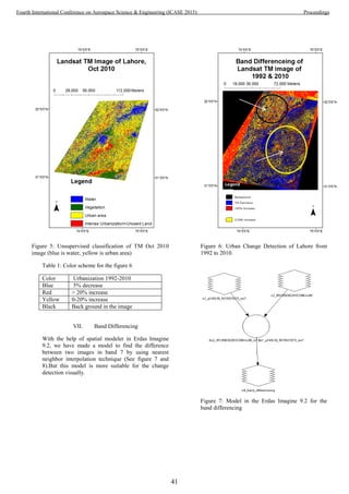
![Figure 8: Band differencing of TM of Lahore (1992-
2010).
Light gray areas in the figure 8 indicate the areas where
urbanization has increased [3].This technique utilized the
differences in brightness value of one pixel to
corresponding pixel of another image. Neutral gray tune
in figure 8 black color represent zeros difference while
white has the maximum difference between the images.
VIII. Red-Green Differencing
This technique is widely used to find the change in the
areas of two images of different times. To detect the
urban change, open the most recent image (2010) in the
red band and old image (1992) in the green band. In the
Erdas Imagine 9.2, we swipe these two images.
Combination of red and green produce yellow color. But
the areas which have changed show reddish color in
image (see figure 9) are the regions where urbanization
has occurred. In remote sensing we cannot use hard
statements about any results. Through this technique we
also verify the areas where the urbanization has occurred
from 1992-2010.
Figure 9: Red-Green Differencing of Landsat Images
1992-2010.
IX. Results and Discussions
This study focused on the important of remote sensing
and GIS techniques in the analyzing of urban change
detection of Lahore and its neighbor cities. This study
shows that digital image processing and GIS can be used
for producing urbanized maps of Lahore. As in remote
sensing we have to rely on the number of remote sensing
techniques which leading us to one conclusion. We have
used the TM data with the interval of 18 years to
investigate the urbanizations. Change detection tell us that
during the study period urban sprawl of Lahore has been
shifted towards Shahdera, Kala Shah Kako , Sheikupura
and Kamoki where the urbanization has been increased by
20% . For validation of these results we have use the band
differencing and red-green differencing techniques which
shows that old city of Lahore is going to expand in the
urban areas and this pattern of urbanization is shifted
towards Bharia Town, Johar Town, and Chung. In these
areas people are going to make urbanization over than
20% from 1992-2010. According to [3] Lahore was
58977 hectares in 1972 and which now (2009) has
increased to 99173 hectares. Our results matching with
the results of previous study of Lahore’s urbanization of >
20% from 1990 to 2009 has occurred. According to 1998
Census, the average family size of the Lahore city was 7.1
Urbanization
42
Fourth International Conference on Aerospace Science & Engineering (ICASE 2015) Proceedings](https://image.slidesharecdn.com/conferenceproceedingsicase2015final1-160918062150/85/Conference-proceedings-51-320.jpg)
![persons, but during 1998 to 2007, the urbanization rate
has increased against population [5].
X. Conclusions
This effort proved its usefulness in the present scenario of
rising trends of population of Lahore city. With the use of
remote sensing and GIS techniques, we have investigated
new pockets around the Lahore where the citizen makes
more residents and plots. Major areas which are facing
urbanization since 1990 are Kala Shah Kako,
Sheikhopura, Meridke, Bheria Town, Kamoki, Chungm
Raiwind, Shahdera and Johar Towns where urbanizations
from 18 years raised 0-20 % even more than 20%. This
study also guides us Karol,Mohalanwal , Kot Radha
Kishan ,Kasur are the regions where the Government can
plan new resident plots. We suggest that future study on
different land use/ land cover patterns of Lahore. Future
study should be undertaken the loss in the area under
decrease in natural vegetation and agriculture. This study
strongly recommend for Government and urban scholars
that such studies should be revised after nominal time
interval with high resolution satellite imagery like Spot,
QuickBird etc.
ACKNOWLEDGEMENT
Author would like to say thanks of USGS team who
provide him satellite images for research. Also I would
like to say thanks deeply to Dr. Najam Abbas, Secretary
ICASE 2015,Institute of Space Technology, Islamabad
Pakistan for providing his kind contribution, for
publication of this research work.
XI. REFERENCES
[1] District Census Reports for each District
containing General Description of the
District and Broad Analysis of Population
and Housing Data followed by detailed
statistical tables (1998-Census).
[2] Young,X. & Lo, C. P. 'Modelling urban
growth and landscape changes in the Atlanta
metropolitan area', international journal of
geographical science, vol. 17, no. 5, pp.
463,463-488, 2003.
[3] O. Riaz, 'URBAN CHANGE DETECTION
OF LAHORE (PAKISTAN) USING A
TIME SERIES OF SATELLITE IMAGES
SINCE 1972', ASIAN JOURNAL OF
NATURAL & APPLIED SCIENCES., vol. 2,
no. 4, pp. 101,102,103,104, 2013.
[4] Jensen and D. Cowen, 'Remote Sensing of
Urban Suburban Infrastructure and Socio-
economic Attribute', Photogrammetric
Engineering and Remote Sensing, vol. 65,
pp. 611-622, 1999.
V. Mesev, 'The Use of Census Data in
Urban Image Classification.',
Photogrammetric Engineering and Remote
Sensing, vol. 64, no. 5, pp. 431-438, 1998.
C. Lo and X. Yang, 'Drivers of land-use/
land-cover changes and dynamics modeling
for the Atlanta. Georgia Metropolitan Area.',
Photogrammetric Engineering and Remote
Sensing,, vol. 68, no. 10, pp. 1073–1082.,
2002.
[5] ureshi, S. Mahmood, A. S. Almas and R.
Irshad, 'MONITORING
SPATIOTEMPORAL AND MICRO-
LEVEL CLIMATIC VARIATIONS IN
LAHORE AND SUBRUBS USING
SATELLITE IMAGERY AND MULTI-
SOURCE DATA', Journal of Faculty of
Engineering & Technology, vol. 19, pp.
53,55, 2012.
[6] H. XU, X. WANG and G. XIAO, 'A
REMOTE SENSING AND GIS
INTEGRATED STUDY ON
URBANIZATION WITH ITS IMPACT ON
ARABLE LANDS: FUQING CITY,
FUJIAN PROVINCE, CHINA', LAND
DEGRADATION & DEVELOPMENT, vol.
11, p. 303, 2000.
43
Fourth International Conference on Aerospace Science & Engineering (ICASE 2015) Proceedings](https://image.slidesharecdn.com/conferenceproceedingsicase2015final1-160918062150/85/Conference-proceedings-52-320.jpg)
![A Review of Fundamentals of Hyperspectral
Imaging and its Applications
Asad Abbas, Khurram Khurshid
Electrical Engineering Department
Institute of Space Technology
Islamabad, Pakistan
Email: asad.abbas@outlook.com, khurram.khurshid@ist.edu.pk
Abstract—Over the past two decades, hyperspectral imagery
has emerged as an effective tool for geo-observation using
airborne and satellite based systems. Current sensor technologies
are capable of covering large surfaces of earth with exceptional
spatial, spectral and temporal resolutions. These features allows
the use of hyperspectral imaging in numerous remote sensing
applications requiring estimation of physical parameters of many
complex surfaces and identification of visually similar materials
having fine spectral signatures. Moreover, applications of hyper-
spectral imaging are growing rapidly, it has shown enormous
potential in various fields including biomedical, archeology, food
quality control, military defense and conservation of artistic and
historic objects. This review describes the differences between
hyperspectral and multispectral data, fundamentals of hyper-
spectral imaging and focuses on the modern applications of
hyperspectral imagery in precision agriculture, water resource
management and document imaging.
I. INTRODUCTION
Human eye is only able to see in a limited part of electro-
magnetic spectrum and can distinguish between objects based
on their different spectral responses in that narrow spectral
range [1]. However, multispectral imaging sensors have been
developed that are able to acquire an image in infrared and
visible segments of electromagnetic spectrum. Thus allowing
material identification on the basis of their unique spectral sig-
nature in a wide spectral range. Multispectral imaging exploits
the property that each material has its own unique spectral
signatures. Spectrum of a single pixel in a multispectral image
provides information about its constituents and surface of the
material.
Multispectral imaging technology is being used for envi-
ronment and land observational remote sensing from satel-
lite and airborne systems since late 1960s [2]. Multispectral
imaging systems acquire data in a small number of spectral
bands by using parallel sensor arrays. Most of the multispectral
imaging systems uses three to six spectral bands with large
optical band intervals, ranging from visible to near infrared
regions of electromagnetic spectrum for scene observation.
However, such low number of spectral bands are the limiting
factor for discrimination of various materials. The development
of hyperspectral sensing systems over the past two decades
made it possible to acquire several hundred spectral bands
of observational scene in a single acquisition. The increased
spectral resolution of these ”hyperspectral” images allow detail
examination of land surfaces and different materials present
in the observational scene, which was previously not possible
with low spectral resolution of multispectral imaging scanners.
Hyperspectral imaging (HSI), also called imaging spec-
trometer [3], is a technique in which an object is photographed
using several well defined optical bands in broad spectral
range. It was originally implemented on satellite and airborne
platforms for remote sensing applications but during last
two decades, HSI has been applied to numerous applications
including agricultural and water resources control [4], [5],
military defense, art conservation and archeology [6], [7],
medical diagnosis [8], [9], analyses of crime scene details [10],
[11], document imaging [12], forensic medicine [13], food
quality control [14], [15] and mineralogical mapping of earth
surface [16].
This review details the fundamentals of hyperspectral
imaging, discusses the common hyperspectral remote sensing
terminologies and highlights the modern applications of hy-
perspectral imagery in the field of precision agriculture, water
resource management and document imaging.
II. FUNDAMENTALS OF HYPERSPECTRAL IMAGING
Unlike normal 2-D images taken by regular camera, hy-
perspectral images are characterized by their spatial as well
as spectral resolution. The spatial resolution measures the
geometric relationship of the image pixels to each other.
While the spectral resolution determines the variations within
image pixels as a function of wavelength. Table I shows the
spatial and spectral resolution of the current airborne and
space satellite imaging sensors. Due to spectral resolution as
well as spatial resolutions generally hyperspectral images are
referred as hyperspectral data cubes. Figure 1 shows a typical
hyperspectral data cube as a result of hyperspectral imaging.
A. Spatial Resolution
Spatial resolution can be defined as the smallest discernible
detail in an image [17]. Which can be described as the measure
of smallest object in an image, that can be distinguished as a
separate entity in the image. In practical situations clarity of
the image is dictated by it spatial resolution, not the number of
pixels in an image. Spatial characteristics of an image depends
on the design of imaging sensor in terms of its field of view
and its altitude [18]. A finite patch of the ground is captured
by each detector in a remote imaging sensor. Spatial resolution
is inversely proportional to the patch size. The smaller the size
of the patch, higher the details that can be interpreted from the
observed scene.
44
Fourth International Conference on Aerospace Science & Engineering (ICASE 2015) Proceedings](https://image.slidesharecdn.com/conferenceproceedingsicase2015final1-160918062150/85/Conference-proceedings-53-320.jpg)
![Fig. 1. Hyperspectral datacube: for any image pixel a complete spectral curve
is observed [12]
TABLE I. CURRENT SPACEBORNE AND AIRBORNE SYSTEMS
PROVIDING OPTICAL DATA FOR LAND MAPPING
Optical Subsystem Spectral Spectral Spatial Resolution Spatial
Bands (m) Range (µm) Resolution Coverage
Spaceborne
Landsat VNIR-TIR 8 0.45-12.50 15-60 Global
MODIS VNIR-TIR 36 0.40-14.40 250-1000 Global
MERIS VNIR 15 0.39-1.040 300 Global
ASTER VNIR-TIR 15 0.52-11.65 15-90 Global
Hyperion VNIR-SWIR 242 0.40-2.500 30 Regional
ALOS VIS 1 0.52-0.77 2.5 Local
Airborne
AVIRIS VNIR 224 0.38-2.500 4-20 Local
HyMap VNIR-SWIR 128 0.45-2.480 2-10 Local
ROSIS VNIR 115 0.42-0.873 2 Local
DAIS-7915 VNIR-TIR 79 0.45-12 3-10 Local
B. Spectral Resolution
Spectral resolution can be defined as the number of spectral
bands and range of electromagnetic spectrum measured by
the sensor. An imaging sensor might respond to a large
frequency range but still have a low spectral resolution if it
acquires small number of spectral bands. On the contrary, if
a sensor is sensitive to small frequency range but captures
large number of spectral bands has high spectral resolution,
due to its ability to distinguish between scene elements having
close or similar spectral signatures [19]. Multispectral images
have a low spectral resolution, thus unable to resolve finer
spectral signatures present in the scene. Hyperspectral imaging
(HSI) sensors acquire images in numerous contiguous and
extremely narrow spectral bands in mid infrared, near infrared
and visible segments of electromagnetic spectrum. This type
of advance imaging system shows tremendous potential for
material identification on the basis of their unique spectral
signatures [2]. Spectrum of a single pixel in a hyperspectral
image can give considerably more information about the
surface of the material than a normal image.
C. Temporal Resolution
In hyperspectral remote sensing, the temporal resolution
depends on the orbital characteristics of the imaging sensor. It
is generally defined as the time needed by the sensor platform
to revisit and obtain data from the exact same location [20].
Temporal resolution is said to be high if the revisiting fre-
quency of the sensor platform for the exact same location is
high and is said to be low if revisiting frequency is low. It is
normally defined in days.
D. Understanding Spectral Signatures
Materials present on the earth’s surface emit, transmit,
reflect and absorb electromagnetic energy from the sun in their
own unique way. Hyperspectral sensors allows us to measure
all types of electromagnetic energy within a specified range
as it interacts with materials, thus allowing us to observe the
distinct features and changes on earth’s surface. Reflectance
is defined as the percentage of amount of energy bouncing
back from material’s surface. It is a ratio of reflected energy to
incident energy as a function of wavelength [18]. Reflectance is
100% if all the light energy of specific wavelength striking the
object is reflected back to the imaging sensor, on the other hand
reflectance is 0% if all the incident light of specific wavelength
is absorbed by the object. In most practical cases reflectance
values are in between these two extremes.
In a specified range of electromagnetic spectrum, the
reflectance values of different materials present on the earth’s
surface such as soil, forest, water, minerals etc can be plotted
and compared. Such plots are labeled as ”spectral signatures”
or spectral response curves” [21]. Figure 2 demonstrates a
general model of spectral signatures of different materials
present on the earth’s surface. Remotely sensed images can
be classified using these spectral signature plots, as each
material present in an observed scene has its own unique
spectral signature. The more the spectral resolution of an
imaging sensor, the more classification information can be
extracted from spectral signatures. Hyperspectral sensors have
high spectral resolution than multispectral sensors and thus
provide the ability to distinguish more subtle differences
in a scene. Hyperspectral imagery has been utilized by
Fig. 2. A generic scheme of HSI mapping of soil, vegetation and water [22]
geologists for mapping the land and water resources [16]. They
have additionally been utilized to map heavy metals and other
hazardous wastes in historic and active mining areas. Figure 3
shows the spectral response curves of dry bare soil, green
vegetation and clean water.
Figure 3 shows that the reflectance curve for bare soil
has less variations as compared to that of vegetation. This is
because of the fact that the factors that affect soil reflectance
vary in a narrow range of electromagnetic spectrum. These
factors include soil texture, presence of minerals such as iron,
surface roughness and moisture content in soil [21]. Spectral
45
Fourth International Conference on Aerospace Science & Engineering (ICASE 2015) Proceedings](https://image.slidesharecdn.com/conferenceproceedingsicase2015final1-160918062150/85/Conference-proceedings-54-320.jpg)
![Fig. 3. Spectral response curves of soil, vegetation and water [18]
signatures of green vegetation have valleys in the visible
portion of spectrum that indicates the pigmentation of the
plant. Chlorophyll is the primary photosynthetic pigment in
green vegetation [18], it is absorbs strongly in red (670 nm)
and blue (450 nm) regions called the chlorophyll absorption
spectral bands. When a plant is under stress so that the
chlorophyll growth is reduced, in such cases the amount of
reflectance in red (670 nm) regions increases [18]. The spectral
response of water has a distinctive characteristics of absorption
of light in near infrared and beyond. Common factors affecting
spectral response of water are the suspended sediments and
increases in chlorophyll levels. In each cases spectral response
will be shifted accordingly showing the presence of suspended
sediments or algae in water [21].
III. APPLICATIONS OF HYPERSPECTRAL IMAGING
A. Precision Agriculture
Many studies have indicated that the world’s crop
production needs to be doubled by the end 2050 due to
the rapid increase in world’s population [23]. However,
various studies have shown that the crop yields are not longer
increasing at a rate to fulfill the growing population needs
[24], [25]. Recent studies have indicated that increasing
crop yields, rather than using more land for cultivation,
is the most effective path for ensuring food security [26],
[27]. Global poverty and undernourishment can directly be
reduced by increasing crop production, moreover most of
the poor and undernourished population consists of farmers
themselves [28].
Traditionally crop monitoring for disease, water stress,
nutrients and insect attack was carried out by manual visual
inspection from the ground. These methods were limited by
the fact that the visual symptoms often appear at later stages
of disease, thus making it difficult to restore plant health.
Advancement in airborne and ground based hyperspectral
imaging methods has made possible the evaluation of crop
stresses, analyzing soil and vegetation characteristics in a
cost effective manner, thus replacing the traditional scouting
methods.
Drought stress is an important factor affecting crop
yields. Chances of a successful crop can be highly increased
by timely detection of water related stresses. High water
level stresses are noticeable in variations in photosynthetic
pigments. These changes leads to yellowish tint in crops, due
to the increase reflectance of red wavelength. Unlike human
eye, hyperspectral imaging sensors can detect these changes
at earlier stages. Colombo et al. [29] indicated that changes
in leaf equivalent water thickness (EWT) was responsible
for changes in leaf reflectance in the infrared and visible
spectrum. They stated that hyperspectral regression indices
calculated from hyperspectral imaging were powerful tools
for estimation of water content at leaf as well as at landscape
level. Rascher et al. [30] used a portable hyperspectral
imaging system and photochemical reflectance index to
estimate water stress in leaves of tropical tress and observed
the temporal effects of dehydrations on tree leaves. Rossini
et al. [31] found that hyperspectral imaging is useful in
detecting drought stress at farm level with corn. They showed
that irrigation deficits can be accurately mapped well before
drought stress affected the canopy structure.
Deficiencies in nutrients and soil contamination causes
various symptoms that can be assessed by hyperspectral
imaging. Schuerger et al. [32] used hyperspectral imaging to
observe zinc deficiency and toxicity to determine chlorophyll
levels relating to stress symptoms. They indicated that
traditional direct sampling methods are much more costly
than hyperspectral imaging. Dunagen et al. [33] analyzed
mercury levels in mustard plants and found that spectral
signatures were notably related to the contaminant levels.
Osborne et al. [34] showed that biomass, yield under
stress, nitrogen and phosphorous concentrations can be
estimated by using hyperspectral imaging. Mahlein et al. [35]
studied different development stages of diseased suger beet
leaves using hyperspectral imaging. Figure 4 shows spectral
signatures of healthy as well as diseased sugar beet leaves.
This study also showed that hyperspectral imaging has a great
potential for analyzing plant diseases.
Analysis of soil characteristics can play a vital role in
Fig. 4. Spectral signatures comparison of healthy and diseased suger beet
leaves [35]
increasing crop yields. Ben-Dor et al. [36] al successfully
mapped vital characteristics of soil in a field scale experiment
including moisture, soil organic matter and soil sanity. Rossel
and Bratney [37] estimated the organic carbon content in soil
with accuracy.
B. Water Resource Management
Water is one of the most important resource available
on the earth and is vital for survival of humanity. For this
46
Fourth International Conference on Aerospace Science & Engineering (ICASE 2015) Proceedings](https://image.slidesharecdn.com/conferenceproceedingsicase2015final1-160918062150/85/Conference-proceedings-55-320.jpg)
![reason, managing the water resource efficiently, analyzing
and monitoring the quality of water has attracted a lot of
attention from the researchers [38], [39], [40], [41], [42], [43].
Hyperspectral remote sensing technology has found enormous
applications in water resource management. Accurate estimates
of water resource parameters are possible by analyzing spatial,
spectral and temporal variations in water bodies.
The efficacy of flood detection and monitoring system is
limited by their incapacity to get important information about
water conditions from airborne and ground observatories in a
timely manner. Recent improvements in remote sensing tech-
nology has improved the early flood warning system and vastly
reduced the time of detection and reaction to flood events
to a few hours [44]. US geological survey and NASA are
incorporating space borne observations of rainfall resources,
rivers and land topography into early warning systems with
potential global applications [45]. Glaber and Reinartz [46]
studies the optimal procedure for detection of flooded areas
with remote sensing data. They investigated the erosive impact
of floods, moisture content in flood plain areas, accumula-
tion of sediments. Roux and Dartus [47] explored the flood
hydrographs and estimated the river discharge from remotely
sensed data. They optimized their model to minimize the error
between system response and their proposed model to estimate
the river discharge.
Hyperspectral remote sensing provides efficient and reli-
able information about water quality parameters which contain
biochemical, hydro-physical and biological attributes [48] [49]
[50]. Hyperspectral imaging enable us to measure chlorophyll,
turbidity and chemical oxygen demand and phosphorous in
water resources. Chlorophyll content in water is extensively
studied by hyperspectral remote sensing, which gives and
estimate of algal level and hence water quality. Studies have
been carried out for evaluation of ammonia changes for
wetland [51], classifying different parameters of lakes [52],
estuaries [53] and analyzing algal blooms [54].
Wetland mapping has played a significant role in order
to enhance the quality of our ecosystem [55]. Hyperspectral
imagery has helped in detailed understanding of vegetation
characteristics of ecosystem. Extensive research studies have
been carried out using remote sensing to explore the signif-
icance of acquiring timely data for monitoring and mapping
aquatic vegetation [56], which is said to be an important aspect
in ecosystem reconstruction and restoration.
C. Document Imaging
Traditionally, forensic document experts and paleographers
used chemical solution based methods to study the extrinsic
and intrinsics components of the important historic docu-
ments [57]. This is due to the fact that the inks used on
documents throughout the history were composed of diverse
substances having distinct chemical and physical properties.
Each of these substances have their own unique way for
reacting with different substrates depending upon the reaction
environment. These chemical solution based methods helped
in document analysis. But unfortunately these techniques were
time consuming, sensitive to temperature changes and destruc-
tive in nature i.e. harms to the important documents were
irreversible.
To overcome such limitations, hyperspectral imaging has
emerged as an effective non-destructive tool for improving
readability [58], ink aging and forensic document analysis [59].
Hyperspectral document imaging works on the principle that
each ink present in the document has its own unique spectral
signature. Many mathematical tools that are being used in
hyperspectral remote sensing can be used on hyperspectral
document images for classification, improving legibility of
extremely deteriorated text, ink aging and fraud detection.
Moreover hyperspectral imaging is non-destructive, automated
and environment insensitive tool for document examination.
In hyperspectral document imaging, ink mismatch de-
tection analysis provides important information to forensic
document examiners to determine the authenticity of legal
documents. Forgery, backdating and fraud can be detected
using ink analysis of documents. Recently, we have worked on
a non-destructive automated hyperspectral document imaging
analysis system, which was able successfully discriminates
between different visually similar ink mixtures (Dataset D1 to
D7) taken from hyperspectral imaging database [60]. Figure 5
shows the final segmentation results of our proposed approach.
Fig. 5. Comparisons of Ground Truth Images (Dataset D1 to D7) with final
segmentation results
IV. DISCUSSION AND CONCLUSION
Among remote sensing technologies, the role of hyperspec-
tral imagery in the geo-observation, identification and detection
of materials and estimation of physical parameters cannot be
stated enough. Due to this very reason there are increasing
number of airborne and spaceborne hyperspectral platforms
based applications being researched. Recent advancement in
47
Fourth International Conference on Aerospace Science & Engineering (ICASE 2015) Proceedings](https://image.slidesharecdn.com/conferenceproceedingsicase2015final1-160918062150/85/Conference-proceedings-56-320.jpg)
![sensor technologies has encouraged researchers to use hyper-
spectral imagery in many modern applications. Many mathe-
matical tools and algorithms are being researched such as data
fusion, hyperspectral unmixing, hyperspectral classification,
anomaly detection and fast computing for efficient utilization
of hyperspectral data. These mathematical tools can be used
on hyperspectral data across many different applications.
In general, this review focuses on the vast extent to which
hyperspectral imaging has been used to increase the crop
yields, managing water resources and its advanced application
in historic and modern document imaging. Promising results
have been found in those areas and also future research is
being carried out for further improvement as well.
REFERENCES
[1] E. H. Land and J. McCann, “Lightness and retinex theory,” JOSA,
vol. 61, no. 1, pp. 1–11, 1971.
[2] D. Landgrebe, “Information extraction principles and methods for
multispectral and hyperspectral image data,” Information processing for
remote sensing, vol. 82, pp. 3–38, 1999.
[3] J. Solomon and B. Rock, “Imaging spectrometry for earth remote
sensing,” Science, vol. 228, no. 4704, pp. 1147–1152, 1985.
[4] M. Govender, K. Chetty, and H. Bulcock, “A review of hyperspectral
remote sensing and its application in vegetation and water resource
studies,” Water Sa, vol. 33, no. 2, 2007.
[5] E. Adam, O. Mutanga, and D. Rugege, “Multispectral and hyperspectral
remote sensing for identification and mapping of wetland vegetation: a
review,” Wetlands Ecology and Management, vol. 18, no. 3, pp. 281–
296, 2010.
[6] C. Fischer and I. Kakoulli, “Multispectral and hyperspectral imaging
technologies in conservation: current research and potential applica-
tions,” Studies in Conservation, vol. 51, no. Supplement-1, pp. 3–16,
2006.
[7] H. Liang, “Advances in multispectral and hyperspectral imaging for
archaeology and art conservation,” Applied Physics A, vol. 106, no. 2,
pp. 309–323, 2012.
[8] O. Carrasco, R. B. Gomez, A. Chainani, and W. E. Roper, “Hyperspec-
tral imaging applied to medical diagnoses and food safety,” in AeroSense
2003. International Society for Optics and Photonics, 2003, pp. 215–
221.
[9] M. A. Afromowitz, J. B. Callis, D. M. Heimbach, L. A. DeSoto, and
M. K. Norton, “Multispectral imaging of burn wounds: a new clinical
instrument for evaluating burn depth,” Biomedical Engineering, IEEE
Transactions on, vol. 35, no. 10, pp. 842–850, 1988.
[10] J. Kuula, I. P¨ol¨onen, H.-H. Puupponen, T. Selander, T. Reinikainen,
T. Kalenius, and H. Saari, “Using vis/nir and ir spectral cameras for
detecting and separating crime scene details,” in SPIE Defense, Security,
and Sensing. International Society for Optics and Photonics, 2012, pp.
83 590P–83 590P.
[11] R. L. Schuler, P. E. Kish, and C. A. Plese, “Preliminary observations
on the ability of hyperspectral imaging to provide detection and visu-
alization of bloodstain patterns on black fabrics,” Journal of forensic
sciences, vol. 57, no. 6, pp. 1562–1569, 2012.
[12] R. Padoan, T. A. Steemers, M. Klein, B. Aalderink, and G. De Bruin,
“Quantitative hyperspectral imaging of historical documents: technique
and applications,” ART Proceedings, 2008.
[13] G. Edelman, E. Gaston, T. Van Leeuwen, P. Cullen, and M. Aalders,
“Hyperspectral imaging for non-contact analysis of forensic traces,”
Forensic science international, vol. 223, no. 1, pp. 28–39, 2012.
[14] A. Gowen, C. O’Donnell, P. Cullen, G. Downey, and J. Frias, “Hyper-
spectral imaging–an emerging process analytical tool for food quality
and safety control,” Trends in Food Science & Technology, vol. 18,
no. 12, pp. 590–598, 2007.
[15] Y.-Z. Feng and D.-W. Sun, “Application of hyperspectral imaging in
food safety inspection and control: a review,” Critical reviews in food
science and nutrition, vol. 52, no. 11, pp. 1039–1058, 2012.
[16] R. N. Clark and G. A. Swayze, “Mapping minerals, amorphous ma-
terials, environmental materials, vegetation, water, ice, and snow, and
other materials: The usgs tricorder algorithm,” in Summaries of the Fifth
Annual JPL Airborne Earth Science Workshop, vol. 1. JPL Publication,
1995, pp. 39–40.
[17] R. C. Gonzalez, Digital image processing. Pearson Education India,
2009.
[18] R. Smith, “Introduction to remote sensing of the environment,” 2001b.
www. microimages. com, 2001.
[19] J. R. Jensen, Introductory digital image processing: A remote sensing
perspective. Pearson College Division, 2005.
[20] J. Thau, “Temporal resolution,” in Encyclopedia of GIS. Springer US,
2008, pp. 1150–1151. [Online]. Available: http://dx.doi.org/10.1007/
978-0-387-35973-1 1376
[21] T. Lillesand, R. W. Kiefer, and J. Chipman, Remote sensing and image
interpretation. John Wiley & Sons, 2014.
[22] G. A. Shaw and H.-h. K. Burke, “Spectral imaging for remote sensing,”
Lincoln Laboratory Journal, vol. 14, no. 1, pp. 3–28, 2003.
[23] D. Tilman, C. Balzer, J. Hill, and B. L. Befort, “Global food demand
and the sustainable intensification of agriculture,” Proceedings of the
National Academy of Sciences, vol. 108, no. 50, pp. 20 260–20 264,
2011.
[24] K. G. Cassman, “Ecological intensification of cereal production sys-
tems: yield potential, soil quality, and precision agriculture,” Proceed-
ings of the National Academy of Sciences, vol. 96, no. 11, pp. 5952–
5959, 1999.
[25] D. K. Ray, N. Ramankutty, N. D. Mueller, P. C. West, and J. A.
Foley, “Recent patterns of crop yield growth and stagnation,” Nature
communications, vol. 3, p. 1293, 2012.
[26] H. C. J. Godfray, J. R. Beddington, I. R. Crute, L. Haddad, D. Lawrence,
J. F. Muir, J. Pretty, S. Robinson, S. M. Thomas, and C. Toulmin, “Food
security: the challenge of feeding 9 billion people,” science, vol. 327,
no. 5967, pp. 812–818, 2010.
[27] J. A. Foley, N. Ramankutty, K. A. Brauman, E. S. Cassidy, J. S. Gerber,
M. Johnston, N. D. Mueller, C. OConnell, D. K. Ray, P. C. West et al.,
“Solutions for a cultivated planet,” Nature, vol. 478, no. 7369, pp. 337–
342, 2011.
[28] P. L. Pingali, “Green revolution: Impacts, limits, and the path ahead,”
Proceedings of the National Academy of Sciences, vol. 109, no. 31, pp.
12 302–12 308, 2012.
[29] R. Colombo, M. Meroni, A. Marchesi, L. Busetto, M. Rossini, C. Gi-
ardino, and C. Panigada, “Estimation of leaf and canopy water content
in poplar plantations by means of hyperspectral indices and inverse
modeling,” Remote Sensing of Environment, vol. 112, no. 4, pp. 1820–
1834, 2008.
[30] U. Rascher, C. J. Nichol, C. Small, and L. Hendricks, “Monitoring
spatio-temporal dynamics of photosynthesis with a portable hyperspec-
tral imaging system,” Photogrammetric Engineering & Remote Sensing,
vol. 73, no. 1, pp. 45–56, 2007.
[31] M. Rossini, F. Fava, S. Cogliati, M. Meroni, A. Marchesi, C. Panigada,
C. Giardino, L. Busetto, M. Migliavacca, S. Amaducci et al., “Assessing
canopy pri from airborne imagery to map water stress in maize,” ISPRS
Journal of Photogrammetry and Remote Sensing, vol. 86, pp. 168–177,
2013.
[32] A. C. Schuerger, G. A. Capelle, J. A. Di Benedetto, C. Mao, C. N.
Thai, M. D. Evans, J. T. Richards, T. A. Blank, and E. C. Stryjewski,
“Comparison of two hyperspectral imaging and two laser-induced
fluorescence instruments for the detection of zinc stress and chlorophyll
concentration in bahia grass (paspalum notatum flugge.),” Remote
sensing of environment, vol. 84, no. 4, pp. 572–588, 2003.
[33] S. C. Dunagan, M. S. Gilmore, and J. C. Varekamp, “Effects of mercury
on visible/near-infrared reflectance spectra of mustard spinach plants
(brassica rapa p.),” Environmental Pollution, vol. 148, no. 1, pp. 301–
311, 2007.
[34] S. Osborne, J. S. Schepers, D. Francis, and M. R. Schlemmer, “De-
tection of phosphorus and nitrogen deficiencies in corn using spectral
radiance measurements,” Agronomy journal, vol. 94, no. 6, pp. 1215–
1221, 2002.
[35] A.-K. Mahlein, U. Steiner, C. Hillnh¨utter, H.-W. Dehne, and E.-C.
Oerke, “Hyperspectral imaging for small-scale analysis of symptoms
48
Fourth International Conference on Aerospace Science & Engineering (ICASE 2015) Proceedings](https://image.slidesharecdn.com/conferenceproceedingsicase2015final1-160918062150/85/Conference-proceedings-57-320.jpg)
![caused by different sugar beet diseases,” Plant methods, vol. 8, no. 1,
p. 3, 2012.
[36] E. Ben-Dor, K. Patkin, A. Banin, and A. Karnieli, “Mapping of several
soil properties using dais-7915 hyperspectral scanner data-a case study
over clayey soils in israel,” International Journal of Remote Sensing,
vol. 23, no. 6, pp. 1043–1062, 2002.
[37] C. Gomez, R. A. V. Rossel, and A. B. McBratney, “Soil organic
carbon prediction by hyperspectral remote sensing and field vis-nir
spectroscopy: An australian case study,” Geoderma, vol. 146, no. 3,
pp. 403–411, 2008.
[38] F. Zagolski, V. Pinel, J. Romier, D. Alcayde, J. Fontanari, J. Gastellu-
Etchegorry, G. Giordano, G. Marty, E. Mougin, and R. Joffre, “Forest
canopy chemistry with high spectral resolution remote sensing,” Inter-
national Journal of Remote Sensing, vol. 17, no. 6, pp. 1107–1128,
1996.
[39] G. P. Asner, “Biophysical and biochemical sources of variability in
canopy reflectance,” Remote sensing of Environment, vol. 64, no. 3, pp.
234–253, 1998.
[40] K. McGwire, T. Minor, and L. Fenstermaker, “Hyperspectral mixture
modeling for quantifying sparse vegetation cover in arid environments,”
Remote Sensing of Environment, vol. 72, no. 3, pp. 360–374, 2000.
[41] C. Stone, L. Chisholm, and N. Coops, “Spectral reflectance character-
istics of eucalypt foliage damaged by insects,” Australian Journal of
Botany, vol. 49, no. 6, pp. 687–698, 2001.
[42] N. Coops, S. Dury, M.-L. Smith, M. Martin, and S. Ollinger, “Com-
parison of green leaf eucalypt spectra using spectral decomposition,”
Australian journal of botany, vol. 50, no. 5, pp. 567–576, 2002.
[43] E. Underwood, S. Ustin, and D. DiPietro, “Mapping nonnative plants
using hyperspectral imagery,” Remote Sensing of Environment, vol. 86,
no. 2, pp. 150–161, 2003.
[44] F. Ip, J. Dohm, V. Baker, T. Doggett, A. Davies, R. Castano, S. Chien,
B. Cichy, R. Greeley, R. Sherwood et al., “Flood detection and
monitoring with the autonomous sciencecraft experiment onboard eo-1,”
Remote Sensing of Environment, vol. 101, no. 4, pp. 463–481, 2006.
[45] G. Brakenridge, E. Anderson, and S. Nghiem, “Satellite microwave
detection and measurement of river floods,” in AGU Spring Meeting
Abstracts, vol. 1, 2006, p. 05.
[46] C. Gl¨aßer and P. Reinartz, “Multitemporal and multispectral remote
sensing approach for flood detection in the elbe-mulde region 2002,”
Acta hydrochimica et hydrobiologica, vol. 33, no. 5, pp. 395–403, 2005.
[47] H. Roux and D. Dartus, “Use of parameter optimization to estimate a
flood wave: Potential applications to remote sensing of rivers,” Journal
of Hydrology, vol. 328, no. 1, pp. 258–266, 2006.
[48] M. Chawira, T. Dube, and W. Gumindoga, “Remote sensing based
water quality monitoring in chivero and manyame lakes of zimbabwe,”
Physics and Chemistry of the Earth, Parts A/B/C, vol. 66, pp. 38–44,
2013.
[49] T. Kutser, B. Paavel, C. Verpoorter, T. Kauer, and E. Vahtm¨ae, “Remote
sensing of water quality in optically complex lakes,” in Proceedings of
the XXII Congress of the International Society for Photogrammetry and
Remote Sensing, Melbourne, Australia, 2012.
[50] S. Koponen, “Remote sensing of water quality: the development and
use of water processors available in beam,” Finland, Helsinki: Helsinki
University of Technology TKK, Department of Radio Science and
Engineering, pp. 1–58, 2006.
[51] D. R. Tilley, M. Ahmed, J. H. Son, and H. Badrinarayanan, “Hyper-
spectral reflectance of emergent macrophytes as an indicator of water
column ammonia in an oligohaline, subtropical marsh,” Ecological
Engineering, vol. 21, no. 2, pp. 153–163, 2003.
[52] S. Thiemann and H. Kaufmann, “Lake water quality monitoring using
hyperspectral airborne dataa semiempirical multisensor and multitem-
poral approach for the mecklenburg lake district, germany,” Remote
sensing of Environment, vol. 81, no. 2, pp. 228–237, 2002.
[53] J.-M. Froidefond, L. Gardel, D. Guiral, M. Parra, and J.-F. Ternon,
“Spectral remote sensing reflectances of coastal waters in french guiana
under the amazon influence,” Remote Sensing of Environment, vol. 80,
no. 2, pp. 225–232, 2002.
[54] R. P. Stumpf, “Applications of satellite ocean color sensors for monitor-
ing and predicting harmful algal blooms,” Human and Ecological Risk
Assessment: an International Journal, vol. 7, no. 5, pp. 1363–1368,
2001.
[55] K. Schmidt and A. Skidmore, “Spectral discrimination of vegetation
types in a coastal wetland,” Remote sensing of Environment, vol. 85,
no. 1, pp. 92–108, 2003.
[56] L. Yuan and L. Zhang, “Identification of the spectral characteristics of
submerged plant vallisneria spiralis,” Acta Ecologica Sinica, vol. 26,
no. 4, pp. 1005–1010, 2006.
[57] V. Aginsky, “Forensic examinaton of” slightly soluble” ink pigments
using thin-layer chromatography,” Journal of Forensic Sciences, vol. 38,
pp. 1131–1131, 1993.
[58] S. J. Kim, F. Deng, and M. S. Brown, “Visual enhancement of old
documents with hyperspectral imaging,” Pattern Recognition, vol. 44,
no. 7, pp. 1461–1469, 2011.
[59] G. Edelman, E. Gaston, T. Van Leeuwen, P. Cullen, and M. Aalders,
“Hyperspectral imaging for non-contact analysis of forensic traces,”
Forensic science international, vol. 223, no. 1, pp. 28–39, 2012.
[60] A. Abbas, K. Khurshid, and F. Shafait, “Ink Mismatch Detection using
Hyperspectral Document Image Analysis,” Master’s thesis, Institute of
Space Technology, Islamabad, Pakistan, 2015.
49
Fourth International Conference on Aerospace Science & Engineering (ICASE 2015) Proceedings](https://image.slidesharecdn.com/conferenceproceedingsicase2015final1-160918062150/85/Conference-proceedings-58-320.jpg)
![A Numerical Study on the Impact Resistance of
Braided Composites
X. Lei
Dept. of Mechanical
Eng., Hanyang
University, South
Korea
K. Hayat
Dept. of Mechanical Eng.,
University of Lahore, Lahore,
Pakistan
Email: khazar.hayat@me.uol.edu.pk
M. T. Hussain
Satellite Research
and Development
Center, Lahore,
Pakistan
H. T. Ali
Dept. of Aerospace Eng.,
Queen's Building,
University of Bristol,
BS8 1TR, UK
R. S. Choudhry
Dept. of Mechanical Eng.,
National University of
Science and Technology,
Islamabad, Pakistan
Abstract— Braided fabric reinforced composites are
attractive alternatives to conventional prepreg laminates due to
higher impact resistant performance. For the development of
aerospace structures made of braided composites, the numerical
simulations can play a key role in reducing time and cost.
However, the numerical tools to evaluate the impact response and
to investigate the damage mechanism of these materials, are not
fully developed yet. This work focuses on the numerical
modelling and analysis of the impact induced response of braided
composites under different impact velocities, using micro-
mechanics of failure (MMF) together with progressive damage
models for fibre and matrix constituents. For implementation of
MMF, the meso- and micro-scale models of unit cell have been
utilized. In the meso-scale unit cell of the braided composites, the
tows effective material properties were updated using a micro
unit cell for which the degradation of constituent material
properties was incorporated. The impact induced damage
progression for the tows and pure matrix was then evaluated.
The impact analyses were performed for bi-axial braided
composites at 45 degrees and 25 degrees braiding angles to
demonstrate the feasibility of the MMF-based approach.
Moreover, the impact response of the braided composites with
both thermosetting and thermos-plastic resin system was also
investigated.
Keywords— Braided composites, Impact resistance, Micro-
mechanics of failure, Progressive damage model
I. INTRODUCTION
Recently, a rapid growth of the applications of textile
braided fabric reinforced composites have been observed in
the marine, aerospace and automobile industries etc. due to its
net-shape fabrication and resistance to delamination damage
and impact load in particular [1]. However, the behavior of the
braided composites is not fully understood yet, and there is a
need of establishing a methodology that can predict the
material failure behaviors under different types of loadings,
primarily the impact loading [2].
The purpose of this study is to evaluate the behavior of
braided composites subjected to impact load with
thermoplastic and thermosetting resin systems, based on
various braiding angles and using micromechanics of failure
(MMF) theory [3]. The analysis procedure involves three
scopes: macro, meso and micro, as shown in Fig. 1. A braided
composite can be assumed to be limited to mesoscale. It
consists of tows and pure matrix encapsulating the tows. Thus,
the use of mesoscale unit cell model serves as a bridge for
transformation of stresses and effective material properties
between the macro level and micro level analyses.
II. MICROMECHANICS-BASED PROGRESSIVE DAMAGE MODEL
A. Geometric modeling of braided composites
The development of an idealized model of the braided
composites is necessary to predict their material behaviors.
The fiber bundle arrangements are modelled using the
geometrical parameters (i.e. braiding angle, width and
thickness of axial tow, width and thickness of bias tow, and
gap between bias tows) illustrated in Fig. 2. Moreover, in the
modeling, the undulation of tows plays a pivotal role in
determining the behavior of the braided composites. Further
details on modeling procedure and techniques can be found in
[2].
Fig. 1. Analysis of braided composites.
B. Meso and micro analyses
The meso- and micro-level analyses are bridged to
characterize the material behaviour of the tows of the braided
Fig. 2. Modeling of braided composites.
50
Fourth International Conference on Aerospace Science & Engineering (ICASE 2015) Proceedings](https://image.slidesharecdn.com/conferenceproceedingsicase2015final1-160918062150/85/Conference-proceedings-59-320.jpg)
![composites. It should be noted that a tow can be approximated
as a curved continuous unidirectional (UD) lamina, and a
micro unit cell, shown in Fig. 3c, can be used to relate the
constituent behaviour to the tow behaviour. Thus, tow stresses
can be transformed into each constituent stresses, and resulting
constituent damages can be used to determine the tow damage.
For the constituent damage analysis, the degradation of the
constituent stiffness properties is carried out, and the tow
effective material properties are subsequently updated through
the micro unit cell.
Fig. 3. Estimation of effective material properties of tows of braided
composites.
The transformation between the tows stresses at meso-
level, denoted by , and the fiber and matrix stresses at
micro-level, denoted by , and , is carried using the stress
amplification factors (SAFs), denoted by and matrices, as
following [3, 4]:
(1)
Eq. (1) can be written in detailed form, as following [4]:
(2)
In a similar manner, the meso strain and temperature
increment can also be transformed to micro strains, as shown
in Eq. 3, using the strain amplification factors which can be
derived from SAFs using the constituent compliance matrix
and the unit cell compliance matrix .
(3)
C. Damage model of micro-constituents
For each constituent, a separate failure criterion is used
due to their distinct mechanical behaviors. Considering the
isotropic nature of the matrix constituent, the von Mises
failure criterion [3, 5] is used, which follows:
(4)
where , , , and represents the first stress invariant,
von Misses equivalent stress, tensile strength and compressive
strengths of matrix constituent, respectively. The failure
criterion described by Eq. 4 matches the condition that the
Stassi’s equivalent stress , reaches the matrix tensile
strength :
(5)
where the symbol represents the ratio of the compressive
strength to the tensile strength of the matrix constituent.
Further, the equivalent stress can be transformed into the
equivalent strain of the matrix constituent, described in Eq. 6,
using the stress-strain relations.
(6)
where , , and represents the first strain invariant, the
von Mises equivalent strain and the Poisson’s ratio of the
matrix constituent.
It should be noted that the equivalent strain, like the
equivalent stress, is a scalar quantity that is computed from the
strain components. Fig. 4a represents a multi-linear stress-
strain model defined using the equivalent stress and the
equivalent strain, to estimate the matrix constituent damage.
The matrix constituent behaves in a linear manner, before the
occurring of any damage. Once damage occurs, the matrix
constituent demonstrates a nonlinear behavior (i.e. hardening
followed by the softening depending on the damage status).
The stiffness of the matrix constituent is degraded by a factor
as following:
(7)
subjected to the condition: . The symbols
and denotes the matrix yield stress and the matrix
yield strain at the beginning, and the symbols and
denotes the matrix yield stress and matrix yield strain at the
end of ith step. The symbol denotes the current equivalent
strain of the matrix at the ith step, and the symbol denotes
the matrix intact stiffness.
For the mesoscale model, the damage in the pure matrix
was modeled using Eq. 8 only, and additional MMF-based
damage modeling using a micro unit cell was used for the
matrix of tows [6]. The periodic boundary conditions were
used for the meso and micro unit cells [2, 7]. The micro unit
cell model, based on the MMF theory and linear material
model, delivered multi-axial micro stress state for the fibre
and the matrix constituents (i.e. assuming perfect bonding for
interface). To avoid computation instability, the maximum
local damage value for fiber and matrix constituent was set to
0.9 [8].
The mesoscale stresses were applied on the micro unit
cell. After performing the finite element analysis, the micro
stresses/strains in the matrix were computed, as shown in Fig.
5. Afterwards, the damage analysis for the matrix was
performed. For the matrix of tow, the localization of damage
51
Fourth International Conference on Aerospace Science & Engineering (ICASE 2015) Proceedings](https://image.slidesharecdn.com/conferenceproceedingsicase2015final1-160918062150/85/Conference-proceedings-60-320.jpg)
![was avoided by using a volume-based damage
homogenization technique, represented by Eq. 8 shown below:
(8)
where the symbol denotes a positive weighing factor,
and the symbol denotes the matrix overall volume in the
micro unit cell.
After estimation of damage status, the tow effective
material properties in the meso unit cell model were re-
evaluated from the micro unit cell and the matrix material
properties were degraded. Afterwards, the damage
propagation inside the tows and the pure matrix was
evaluated. For the matrix constituent, following constitutive
relation was used to degrade the stiffness:
(9)
where denotes the stiffness of matrix zone in the micro
unit cell.
For the fiber constituent, the maximum stress failure
criterion, which is , was used for the fiber
constituent. The symbol presents the micro longitudinal
stress of the fiber constituent, and symbols and denotes
the longitudinal tensile strength and longitudinal compressive
strength of the fiber constituent, respectively. Fig. 4b
illustrates that when the fiber constituent fails its stiffness is
dramatically degraded. Since, carbon fiber behaves in a brittle
manner, therefore, the highest value of all elemental damage
factors was considered, as following:
(10)
where the symbol denotes the damage factor of jth
element of the fiber constituent. And, the constitutive relation
for fiber constituent was:
(11)
where denotes the stiffness of overall fiber zone in the
micro unit cell.
D. Numerical implementation
Fig. 6 illustrates the flow chart of the algorithm developed
for combining the MMF methodology and progressive damage
model. In the beginning, the total global strain, denoted
by , is computed at the global time , and augmenting the
global strain increment, denoted by , to global strain at
previous time-step n-1. For the tows, the macro stresses of
each tow element, denoted by , are estimated using the
previous effective stiffness properties, denoted by .
Afterwards, the micro stresses for each element of the both
matrix and fiber zones in the micro unit cell, denoted by
and , are computed from the meso stress, denoted by ,
by using SAFs. The constituent failure criteria are then applied
to both matrix and fiber, and damage factor is estimated for
each jth element in the matrix and fiber zones, denoted by
and , respectively, by employing the relevant constituent
damage models. The overall damage factor for both matrix
and fiber zones, denoted by and , are then evaluated
based on their respective damage methods (i.e. the damage
homogenization for the matrix constituent, and the maximum
damage for fiber constituent, as discussed previously).
Based on the status of overall damage factor, the stiffness
properties of the matrix and fiber are degraded, and the tow
effective properties are evaluated for the next time increment.
The numerical implementation was done using Abaqus 6.11-1,
a commercial finite element solver, combined with its user
subroutine VUSDFLD [9].
Fig. 4. (a) Multi-linear model for the matrix constituent damage, and (b)
linear model for the fiber constituent damage.
Fig. 5. Damage estimation of the matrix constituent: (a) applied load; (b)
micro stresses; (c) element damage factor; (d) overall damage factor.
Fig. 6. Algorithm combining the MMF methodology and progressive
damage model.
52
Fourth International Conference on Aerospace Science & Engineering (ICASE 2015) Proceedings](https://image.slidesharecdn.com/conferenceproceedingsicase2015final1-160918062150/85/Conference-proceedings-61-320.jpg)
![III. MATERIAL PROPERTIES
The stiffness properties of carbon fiber constituent are
listed in TABLE 1 [1]. However, the strength properties of
carbon fibers, shown in TABLE 1, were back-calculated using
micromechanics approach. The stiffness and strength
properties of the matrix constituent, listed in TABLE 2, were
taken from in-house material testing database.
TABLE 1. MATERIAL PROPERTIES OF CARBON FIBERS [1].
Material property Value
Longitudinal modulus: Ef1 (GPa) 276.0
Transverse modulus: Ef2 (GPa) 27.6
In-plane shear modulus: Gf,12 (GPa) 138
Transverse modulus: Gf,23 (GPa) 7.8
Major Poisson’s ratio: vf,12 0.3
Major Poisson’s ratio: vf,23 0.8
Longitudinal tensile strength: Tf (MPa) 3800
Longitudinal compressive strength: Cf (MPa) 2980
TABLE 2. MATERIAL PROPERTIES OF THE MATRIX RESIN.
Material property Thermosetting Thermoplastic
Elastic modulus: Em (GPa) 3.45 2
Elastic Poisson’s ratio: vm 0.35 0.35
Final tensile strength: Tm (MPa) 65 65
TABLE 3. TOWS EFFECTIVE MATERIAL PROPERTIES.
Material property
Tows with
thermosetting
resin
Tows with
thermoplastic
resin
Longitudinal modulus: E1 (GPa) 215.67 215.67
Transverse modulus: E2 (GPa) 13.55 13.55
In-plane shear modulus: G12 (GPa) 9.0 9.0
Transverse modulus: G23 (GPa) 4.29 4.29
Major Poisson’s ratio: v12 0.309 0.309
Major Poisson’s ratio: v23 0.592 0.592
The tows effective properties, listed in TABLE 3, were
computed from micro unit cell, using the stiffness properties
of the matrix and fiber constituents, along with a fiber volume
fraction of 0.78. It should be noted that the total fiber volume
fraction of the meso unit cell was approximately 0.5,
computed in accordance with [2]. The multi-linear damage
models consisting of hardening and softening behaviors,
shown in Fig. 7, for the matrix constituent (i.e. thermoplastic
and thermosetting resin systems) was also established based
on in-house test data.
IV. IMPACT ANALYSIS SETTING
For impact analysis, the whole model of biaxial (BX)
braided fabrics was composed of fiber, pure matrix, matrix in
tows, and a ballistic projectile. For the geometrical modeling
parameters, the tow width and the two thickness used were
3.01 mm and 0.5 mm, respectively. There was a gap of 0.002
mm between the biased tows. The amplitude of the tow
undulation of biaxial braids was set to 0.252 mm. Two kinds
of biaxial braided composites with thermoplastic and
thermosetting resin systems, and each having braided angle of
45 degrees and 25 degrees, hereafter denoted with BX45 and
BX25, respectively, were investigated.
For the ballistic projectile, the radius was 4 mm. The
initial position of the projectile was set above the braided
fabric model and the gap between the bottom of the projectile
and the top surface of the braided models was set to 0.1 mm.
Fixed boundary conditions were applied on the all four sides
of the braided composites, and the top and bottom boundaries
of the braided model were assigned with free boundary
conditions. The ballistic projectile was taken as a rigid body
controlled by a reference point, which was constrained to
move only in z-direction. As illustrated in Fig. 8, the projectile
was given an initial velocity, and the contact properties were
also assigned on the braided model and the projectile by
setting a value of 0.28 for the coefficient of friction. Once the
projectile touches the top surface of the braided model, the
contact behavior will be taken into account. Two initial
velocities of 20 m/s and 50 m/s were applied to the projectile.
At initial velocity of 20 m/s, no penetration occurred and
projectile bounced back after impact. However, at initial
velocity of 50 m/s, the projectile penetrated through the
braided composite.
V. RESULTS AND DISCUSSION
Fig. 9 shows the damage contours for the BX45 braided
composite models, with thermoplastic and thermosetting
resins, at the impact velocity of 50 m/s. For the pure matrix
and the matrix in tows, the damage contour with element
deletion are shown in Fig. 9(a-c) and Fig. 9(b-d), respectively.
Fig. 7. Stress-strain behaviors of the matrix resin systems.
Fig. 8. Impact analysis of various types of biaxial braided
composites: (a) braids at 45 degrees, and (b) braids at 25 degrees.
53
Fourth International Conference on Aerospace Science & Engineering (ICASE 2015) Proceedings](https://image.slidesharecdn.com/conferenceproceedingsicase2015final1-160918062150/85/Conference-proceedings-62-320.jpg)
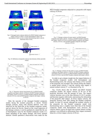
![On the contrary, the impact resistance of the braided
composite model with thermoplastic and thermosetting resins,
can be clearly distinguished at the projectile impact velocity of
50 m/s, as shown in Fig. 11(c-d). It should be noted that the
projectile with a higher impact velocity of 50 m/s, penetrates
through the braided composite model, as can be seen from the
velocity time histories. The residual velocity of the projectile
decreases with the passage of time, but remains positive
throughout the recorded time of 0.2 seconds. For both BX45
and BX25 braided composite model with thermoplastic resin,
the residual velocity of the projectile is clearly lower than that
of the braided composite model with thermosetting resin. The
decrease in residual velocity of the projectile means that the
impact energy is absorbed by the braided composite model.
Higher the decrease in the residual velocity of the projectile,
the higher would be the impact energy absorption. Based on
this fact, it can be inferred that the braided composite model
with thermoplastic resin exhibits better impact resistance than
that of the braided composite model with thermosetting resin.
Fig. 12 and Fig. 13 show that the impact damage evolution
for the pure matrix and for the matrix in tows, respectively, of
the BX45 and BX25 braided composite models with
thermoplastic and thermosetting resin systems. For the pure
resin, it can be seen that the highest damage occurs for both
BX45 and BX25 braided composite models with
thermosetting resin (Fig. 12), for the impact velocities of 20
m/s and 50 m/s.
TABLE 4. PERCENTAGE ELEMENT DELETION.
Impact
velocity
(m/s)
Percentage
element
deletion
in (%)
BX45 Braided
composite
BX25 Braided
composite
Thermo-
plastic
resin
Thermo-
setting
resin
Thermo-
plastic
resin
Thermo-
setting
resin
20
Pure matrix 2.38 5.38 3.05 5.29
Tow matrix 0.09 0.14 0.18 0.31
50
Pure matrix 14.0 20.57 13.59 19.36
Tow matrix 1.89 2.04 1.71 1.84
However, in the case of the matrix in tows, the highest
damage occurs for the BX45 and BX25 braided composite
models with thermoplastic resin (Fig. 13), for impact
velocities of 20 m/s and 50 m/s. It can also be clearly seen that
the damage values of the matrix in the tows are higher in
magnitude than that of the pure matrix. Thus, overall damage
status of the braided composite model is governed by the
matrix in tows. Moreover, higher impact damage values also
mean that more absorption of the impact energy and higher
reduction in the residual velocity of the projectile after impact,
as previously illustrated in Fig. 11. Since, damage values of
the matrix in tows for the braided composite model with
thermoplastic resin are higher and well spread (as previous
shown Fig. 9) than that of the braided composite model with
thermosetting resin, therefore, it can be inferred that the
braided composite with thermoplastic resin system can
withstand higher impact loads, thereby, demonstrate better
impact resistance.
Finally, the percentage element deletion for the braided
composite models with both thermoplastic and thermosetting
resin are compared in TABLE 4. The percentage of element
deletion of the pure resin and of the matrix in tows for the
braided composite with thermoplastic resin system is lower
than that for the braided composite with thermosetting resin
system, as it withstand higher impact loads. Since, the braided
composite with thermoplastic resin system possess better
impact resistance, therefore, the small number of elements
reach the critical damage values that once reach results in the
element deletion.
VI. CONCLUSIONS
A numerical study was carried out to evaluate the impact
resistance of the biaxial (BX) braided composites made of
thermoplastic and thermosetting resin systems, and subjected
to a circular ballistic projectile of radius 4 mm. Two impact
conditions, the bouncing back of projectile with impact
velocity of 20 m/s and the full perpetration of projectile at
impact velocity of 50 m/s, were simulated. Based on the
micromechanics of failure (MMF) theory, the impact
resistance of the braided composite models was evaluated in
terms of the damage evolution in the pure matrix and the
matrix in the tows, and the percentage of element deletion.
Results showed that the braided composites with thermoplastic
resin demonstrate better impact resistance, than that of the
braided composite with thermosetting resin, for both 45
degrees and 25 degrees braiding angles and for all impact
conditions. From the numerical simulations, it was difficult to
evaluate the effect of braiding angles on the impact resistance
of the braided composites, and requires further investigation.
Moreover, future work will involve the validation of the
MMF-based impact analysis methodology, presented here,
with the experimental data.
ACKNOWLEDGMENT
The authors are thankful to the their colleagues Professor
Dr. Iqbal Hussain and Associate Professor Dr. Aamir Khan of
Mechanical Department at the University of Lahore, Main
campus, 1-kM Raiwind Road, Lahore, Pakistan, for their
timely help and support.
REFERENCES
[1] Sun, X.S., V.B.C. Tan, and T.E. Tay, Micromechanics-based
progressive failure analysis of fibre-reinforced composites with non-
iterative element-failure method. Computers and Structures, 2011.
89(11-12): p. 1103-1116.
[2] Xu, L., et al., Prediction of material properties of biaxial and triaxial
braided textile composites. Journal of Composite Materials, 2012.
46(18): p. 2255-2270.
[3] Ha, S.K., et al., Micromechanics of Failure for Ultimate Strength
Predictions of Composite Laminates. Journal of Composite Materials,
2010. 44(20): p. 2347-2361.
[4] Jin, K.-K., et al., Distribution of Micro Stresses and Interfacial Tractions
in Unidirectional Composites. Journal of Composite Materials, 2008.
42(18): p. 1825-1849.
[5] Raghava, R., R.M. Caddell, and G.S.Y. Yeh, The macroscopic yield
behaviour of polymers. Journal of Materials Science, 1973. 8(2): p. 225-
232.
55
Fourth International Conference on Aerospace Science & Engineering (ICASE 2015) Proceedings](https://image.slidesharecdn.com/conferenceproceedingsicase2015final1-160918062150/85/Conference-proceedings-64-320.jpg)
![[6] Fish, J. and Q. Yu, Two-scale damage modeling of brittle composites.
Composites Science and Technology, 2001. 61(15): p. 2215-2222.
[7] Xia, Z., Y. Zhang, and F. Ellyin, A Unified Periodical Boundary
Conditions for Representative Volume Elements of Composites and
Applications. International Journal of Solids and Structures, 2003. 40(8):
p. 1907-1921.
[8] Hashimoto, M., et al., Prediction of tensile strength of discontinuous
carbon fiber/polypropylene composite with fiber orientation distribution.
Composites Part A: Applied Science and Manufacturing, 2012. 43(10):
p. 1791-1799.
[9] Roget, B. and I. Chopra, Wind-tunnel testing of rotor with individually
controlled trailing-edge flaps for vibration reduction. Journal of Aircraft,
2008. 45(3): p. 868-879.
56
Fourth International Conference on Aerospace Science & Engineering (ICASE 2015) Proceedings](https://image.slidesharecdn.com/conferenceproceedingsicase2015final1-160918062150/85/Conference-proceedings-65-320.jpg)
![Improving Physical and Mechanical Properties of
Medium Density Fibreboard (MDF)
Waheed Gul
Mechanical Engineering Department
CECOS University of IT & Emerging Sciences
Peshawar, Pakistan
waheed@cecos.edu.pk
Afzal Khan, Abdul Shakoor
Mechanical Engineering Department
University of Engineering & Technology
Peshawar, Pakistan
Abstract— Physical and mechanical properties play a vital
role in Medium Density Fiberboard (MDF) Manufacturing. Urea
Formaldehyde (UF) resins is easily soluble in water and act as a
binder with fibers. It has fast rate of reaction but has a poor
physical and mechanical properties. Hence, there is a need to
improve those properties of UF resin. The current research is
based to investigates and analyze the UF resin to improve its
physical and mechanical properties in manufacturing of MDF.
The Melamine resin and basic green (Malachite Green) 4-crystals
were introduced into UF resin, separately. In both cases, a
significant improvement in physical and mechanical properties of
UF resin was observed. Additionally, economic analysis was
carried out for both additives and it was concluded that
Melamine is not only economically feasible but also gives
superior mechanical and physical properties when compared to
Malachite green doped resin. The resulted MDF with Melamine
doped resin resulted in strong mechanical adhesion, and water
resistance Keywords—component; formatting; style; styling;
insert (key words)
I. INTRODUCTION
The Medium Density Fiberboard (MDF) is a wood product
processed under heat and pressure by using wood fibers or
other plant fibers as raw materials and application of phenol or
Urea-formaldehyde resin as binder. Other suitable additives
may be added to improve the property of the board.[1].The
density of MDF in production is generally control between
690 – 750 kg/m3.The performance index of MDF is divided
into three categories, i.e. Physical performance, Mechanical
performance and Biological performance.
By nominal density, MDF may be classified in to Type 60, 70,
80. By applicable Conditions, MDF can be classified in to
interior MDF, interior humidity-proof MDF and exterior
MDF.By visual quality and internal bonding strength, MDF
can be classified into Super Grade, Grade A and Grade B. [1].
A. MDF Production Process Flow
MDF production process consists of different stages, i.e.
materials preparation, Fiber separation, Fiber treatment, Mat
forming, Hot pressing, Board trimming and sanding, as shown
in MDF process flow chart in figure.1.
↓
↓
↓
↓
↓
Figure 1.1: Production Process flow of MDF [2].
B. Malachite Green
Basic green (Malachite green) is an organic compound,
basically green powder with Metallic luster. The molecular
formula of Malachite green is C52H54N4O12.
Properties of Malachite green are:
It is easily soluble in water
It is extremely soluble in Ethanol.
Its solution in water is Blue-green.
Basic green dyes become yellow in concentrated
sulphuric acid.
Figure 1.2: Basic Green 4 (Malachite green)
Fiber Separation
Hot Press
Board Trimming
Sanding
Fiber Treatment
Material Preparation
Greeen Crystals
57
Fourth International Conference on Aerospace Science & Engineering (ICASE 2015) Proceedings](https://image.slidesharecdn.com/conferenceproceedingsicase2015final1-160918062150/85/Conference-proceedings-66-320.jpg)
![II. LITERATURE REVIEW
Urea Formaldehyde (UF) resins is used as a binder with fibers
in manufacturing of Medium Density Fiberboard (MDF)
because of its fast rate of reaction, easily soluble in water and
also economically feasible. [3].The only problem is that of
poor water resistance property which limits the uses of MDF.
In order to overcome this problem, a melamine formaldehyde
resin and Malachite Green are added with UF resin. If we
compare the market price of both resin, then it can be easily
understood that Melamine formaldehyde resin is almost 4
times expensive than UF resin. So a very small quantity is to
be added for improving water resistance property. The
Melamine resin can easily soluble in both water and UF resin.
[4]. similarly, the market value of Malachite green is pretty
high. Malachite in our case is added to UF resin. The
Malachite is added for the reason to give a unique color and
extra strength to High Density Fiberboard. As we know that it
is easily solvable in water. So the formulation of Malachite
green is carried out in such a way that it dissolves water before
adding it into UF resin. In other words the solution of
Malachite green was added in definite proportion with water
along with caustic.
Malachite green is prepared in two steps: In ist steps
condensation of of benzaldyde and dimethylniline condensate
and leuco Malachite green in obtained. In second step leuco
compound is oxidize to give malachite green. [5].
𝐶6𝐻5𝐶𝐻𝑂+2𝐶6𝐻5𝑁(𝐶𝐻3)2→𝐶6𝐻5𝐶𝐻(𝐶6𝐻4𝑁(𝐶𝐻3)2)
2+𝐻2𝑂 (1)
𝐶6𝐻5𝐶𝐻(𝐶6𝐻4𝑁(𝐶𝐻3)2)2+𝐻𝐶𝑙+12𝑂2→[𝐶6𝐻5𝐶(𝐶6𝐻4𝑁(𝐶𝐻
3)2)2]𝐶𝑙+𝐻2𝑂 (2)
Manganese dioxide is used as oxidizing agent.
Malachite green can be Hydrolysis and give carbonyl formal.
[𝐶6𝐻5𝐶(𝐶6𝐻4𝑁(𝐶𝐻3)2)2]𝐶𝑙+𝐻2𝑂
→𝐶6𝐻5𝐶(𝑂𝐻)(𝐶6𝐻4𝑁(𝐶𝐻3)2)2+𝐻𝐶𝑙 (3)
Table 1: pH values of Malachite Green in Transition
Uses of Malachite Green:
Malachite green is used as a dye. It is used as antibacterial. In
Microscopic analysis, it is used as a-biological stain. In dye
laser it is used as a saturated absorber. It is also used as a PH
indicator between PH 0.2 – 1.8. [5].
III. MATERIALS AND METHODS
UF and Melamine formaldehyde resin and Malachite Urea
Formaldehyde resin have some properties, i.e. PH value, Gel
time, Viscosity, Specific gravity, Solid content etc.
In order to calculate the above properties the following
methods and procedures are used.
A. pH Value Calculation
There are two methods for calculating the PH value of the
Resin.
One way of measuring the PH value is the use of PH paper.
Procedure: The PH strip is immersed in UF resin for a minute.
Then the strip is taken out and compare the pH value with PH
scale (0- 14) numbers. The PH value of UF resin is from 7.5 –
8.5 means that the UF is alkaline.
Figure 3.1(a): A PH strip is immersed in Resin
In second method, a PH meter is used to measure the PH
(acidity or alkalinity) of UF. It consists of a glass electrode and
electronic meter as shown in fig. The electrode is connected to
the electronic meter that measure and display the PH value.
pH IndicatorUF Resin
Beaker
58
Fourth International Conference on Aerospace Science & Engineering (ICASE 2015) Proceedings](https://image.slidesharecdn.com/conferenceproceedingsicase2015final1-160918062150/85/Conference-proceedings-67-320.jpg)
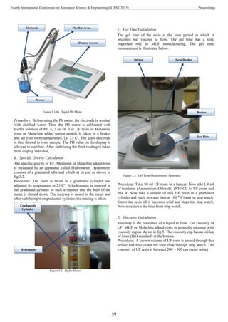


![Table: 4.9: Comparison of 16mm board properties with standard values
Malachite
Figure 4.1: Comparasion of swelling in thickness of UF,MUF Malachite UF
with standard value
Figure 4.2: Comparison of internal Bonding of UF, MUF Malachite UF with
standard value
V. ECONOMIC ANALYSIS
As we know from formulation that:
Melamine consumption /sheet = 0.19 (kg/sheet)
Price of 1 Kg of Melamine = Rs. 150/Kg
Melamine cost per sheet = Rs = 28.5
Similarly,
Malachite Green consumption / sheet = 0.07 (Kg/sheet)
Price of 1 Kg of Malachite Green = Rs = 700 / Kg
Malachite cost per sheet = Rs = 49
Cost Difference = Rs. 20.5
For a 154 M³ capacity plant, Production/day = 3240 sheets
(16mm)
Cost saving /day = Rs. 66420
So it is clear from economic Analysis that Melamine is
also economically better than Malachite Green.
VI. CONCLUSION
In the light of the above parameters, samples of 16mm
board were manufactured using the predefined parameters.
The boards were then tested for their physical and mechanical
properties. The tested boards’ properties were then compared
with the international standards.
The 16mm boards samples using Malachite UF and MUF
resins were manufactured and properties were compared and it
was found that almost all properties were according to the
standards. Moreover, using MUF, the swelling in thickness
property was improved by 15%. And Mechanical adhesion
(which is called internal bond) was increased by 5 %.
Economic Analysis was also carried out and it was analyzed
that Melamine is economically better resin.
ACKNOWLEDGMENT
The author is highly thankful to Ciel Woodworks Pvt.ltd
Peshawar, Pakistan for giving him the opportunity to perform
experiments in lab and use the factory equipment.
REFERENCES
[1] ksh, A, and Hosseikhani, H, (2010), “Investigation on physical and
mechanical properties of Medium Density Fiberboard (MDF) produced
from hornbeam wood”, Volume 25, Number 1 (32); Page(s) 1 To10.
[2] Zwawi Ibrahim, Astimar Abdul Aziz, Ridzuan Ramli, Wan Hassamudin
Wan Hassan and Nahrul Hayawin Zianal (2011), “Optimum Parameters
for the Production of MDF using 100 % Oil Palm Trunks”, “Malaysian
Palm Oil Board, Ministry of Plantation industries and commodities,
Malaysia.ISSN, ppt.1511-7871.
[3] Awang Bono, Yeo Kiam Beng @ Abdul Noor & Kinabalu, Sabah,
(2001),”Melamine-Urea-Formaldehyde Resin: changes in Physical
Properties and Strength with Composition Molar Ratio”, Borneo Science
10: 11-23.
[4] Jizhi Zhang, Xiaomei, Wang, Shiefeng Zhang, Qiang Gao, Jianzhang Li
,(2013),”Effects of Melamine Addition stage on the Performance and
Curing Behavior of Melamine-Urea-Formaldehyde (MFU)
Resin,”,Bejing Forestry University, 100083, Vol 8, No 4.
[5] H. Zare-Hosseinabadi, M. Faezipour1, A. Jahan-Latibari2
andA.Enayati1, J. Agric. Sci. Techno, (2008),”Properties of Medium
S.N
o
Properties
Value
s
Units
EN
standard
s
Test
Method
1 Moisture content 8 % 7 ± 3 EN322
2 Density 725 kg/m3
720-740 EN323
3 Swelling in thickness 12.8 % ≤ 12 EN317
4 Internal Bonding 0.7 N/mm² ≥ 0.6 EN319
5 Modulus of Elasticity 3150 N/mm² 2500 EN310
6 Modulus of Rupture 31.9 N/mm² ≥ 30 EN310
7 Screw Holding face 1001 N ≥ 1000 ASTM1761
8 Screw Holding edge 739 N ≥ 700 ASTM1761
62
Fourth International Conference on Aerospace Science & Engineering (ICASE 2015) Proceedings](https://image.slidesharecdn.com/conferenceproceedingsicase2015final1-160918062150/85/Conference-proceedings-71-320.jpg)
![Density Fiberboard Made from Wet and Dry Stored Bagasse”, Vol. 10:
461-470.
[6] Amee K. Patel, Hardik H. Chaudhary, Khushbu S. Patel and Prof. Dr.
Dhrubo Jyoti Sen,(2014),” Colour of Ecofriendly Dyes Used In Holi
Rather Than Triphenylmethane Dyes”, Volume 3, Issue9, 1287-1305.
[7] Nadir Ayrilmis, (2008),”Effect of Comparison wood on Dimensions
Stability of Medium Density Fiberboard”, University of Istanbul Turkey,
42(2),285-293.
[8] Cristiane Inácio de CamposI, Francisco Antonio Rocco LahrII,
(2004),”Production and characterization of MDF using eucalyptus fibers
and castor oil-based polyurethane resin”, vol.7 no.3
[9] Stefan Ganev, (2003),”Linear Expansion and thickness Swell of MDF as
a Function of Panel Density andSorptionState,””,University
Laval,Quebic,Canada,GIK7P4.
[10] H. Zare-Hosseinabadi, M. Faezipour1, A. Jahan-Latibari2
andA.Enayati1, J. Agric. Sci. Techno, (2008),”Properties of Medium Density
Fiberboard Made from Wet and Dry Stored Bagasse”, Vol. 10: 461-470.
[11] Khalid Pervez Bhatti and Muhammad Zuber, (2009),” Synthesis and
Application of Melamine Urea Based Precondestates”, AUTEX
Research Journal, Vol. 9, No4.
[12] Maintains, G and Berns, J, (2001),”Strawboards bonded with urea
formaldehyde resins”, 35th International Particleboard Composite
Materials Symposium Proceedings, pp.137-144, 2001.
[13] http://www.goodrichsugar.com/mdfnew.asp?no=3, (April12, 2014.
63
Fourth International Conference on Aerospace Science & Engineering (ICASE 2015) Proceedings](https://image.slidesharecdn.com/conferenceproceedingsicase2015final1-160918062150/85/Conference-proceedings-72-320.jpg)
![Finite Element Analysis of Tool Wear in Ultrasonically
Assisted Turning
A. Rehman1
, S.Maqsood1
1
Dept.of Industrial Engineering,
University of Engineering and Technology,
Peshawar,Pakistan
Khattak_rehman@yahoo.com
R.Muhammad2
, N.Ahmed2
2
Dept.of Mechanical Engineering
CECOS University of IT and Emerging Sciences
Peshawar,Pakistan
Abstract—The tremendous increase in use of titanium and its
alloys in different industries, especially in power and aviation
industries demand further investigation due to its exceptional
mechanical and thermal properties. New assisted and hybrid
machining techniques were introduced to obtain better results in
machiningof these alloys. Among many, ultrasonically assisted
turning (UAT) is one of those in which lowervibration energy
impactisdelivered onthe cutting tool in the direction of velocity.
DuringUAT of titanium alloys, momentous improvement has
been noticed in surface roughness smoothness along with
reduction of overall cutting forces, but tool wear behavior is still
unknown. This paper presents a parametric finite element (FE)
analysis for describing tool wear behavior in UAT of (Ti-
15V3Al3Cr3Sn) alloy on the selected cutting conditions. The
model is useful for optimizing of cutting parameters in UAT for
Ti-15V3Al3Cr3Sn. The proposed FE model is also enhances the
recent experimental work on wear behavior relevant to cemented
carbide tool and comparing UAT and conventional turning (CT)
of Ti-15V3Al3Cr3Sn results.
IndexTerms—Tool Wear, Ultrasonically Assisted Turning, Ti
Alloys
I. INTRODUCTION
Machining is an imperative practice in manufacturing and
production industries. Machining put in a substantial portion to
the total cost of the product. Machining cost and production
time are the key apprehensions caused by the frequent abrasion
and replacement of machining tool. Compare to milling,
drilling[1, 2]and grinding processes, turning process is
receiving more importance due to enhanced production rate in
advance industries[3, 4].
Uses of Titanium and its alloys are tremendously increasing
day by day in different industries, especially in power,
petroleum, aviation and biomedical industries[5]. In many
applications, these materials replace steels and aluminum
alloys, which usually results in weight and/or space saving,
increase of system efficiency by rising the service temperature,
and remove the need of protective coatings that should be used
in steels [6]. Increment in the use of these alloys is due to its
outstanding mechanical properties including elevated strength
to density ratio, corrosion resistance, fatigue properties and
strength behavior at moderately high temperatures [7].
Aforesaid materials are therefore fall in a category of difficult-
to-cut materials, because of the fact that these materials are
facing greater challenge to machining processes against the
higher stresses generation and elevated
temperatures[8].Presently, beta titanium is considered as the
most difficult to machine alloys[9].Keeping in view the high
demand of titanium and its alloys machining, researchers have
continuously worked and developed different techniques for
improvement of machinability of these most hard-to-cut
alloys[10]. Such alloys are difficult to machine using
conventional turning(CT) processes and often results in poor
surface finish with associated lack of dimensional accuracy,
built-edge formations, fast tool wear, and undesired chatter
during operations[11].
In recent, new assisted and hybrid machining techniques have
been introduced to get improved machining results of these
hard-to-cut alloys. Among many, ultrasonically assisted
turning (UAT) is one of those in which
lowervibrationalenergy impacts are imposed on the tool in the
direction of velocity[12-14]. This technique has shown
tremendous and noteworthyenhancement in the machinability
of hard-to-cut alloys [15-18]. In UAT, the tool and workpiece
are not in continuous contact that is why net forces are lower
as compared to CT [12], ultimately friction influence are also
lower [13, 14]. The efficiency of UAT and influence of
vibrational parameters on surface roughness is investigated by
Graeviciuteet. Al[15, 16]. However, limited attention has been
given to investigate the tool life in UAT which is the main
concern in manufacturing processes.
Two of the main critical problems are tool wear and tool
failure, which not only raises the production cost but also
affect the product quality. The thorough and continuous
contact between cutting part of tool and workpiece material
generate high cutting forces and temperature in the cutting
region of hard-to-cut alloys. The selection of appropriate tools
for the machining of these alloys using sustainable
conventional machining processes is still not fully understood
and demands for further research to advance the better tool life
and tool wear.
The subject matter of this work is based on the finite element
simulation of UAT of beta titanium alloy to investigate the
tool life under pre-selected cutting conditions. The simulation
results have been compared with CT. This work would help
the industries to estimate tool’s life in UAT.
64
Fourth International Conference on Aerospace Science & Engineering (ICASE 2015) Proceedings](https://image.slidesharecdn.com/conferenceproceedingsicase2015final1-160918062150/85/Conference-proceedings-73-320.jpg)
![II. 3D MODELLING
A 3D model for both CT and UAT processes is developed in
DEFORM 3D V 6.1.In current model cutting tool of
Fig.1. Tool and workpiece FE mesh
Tungsten Carbide with (AlTiN) coating is assumed to be
elastoplastic with considering a rake angle as 14.6º, nose angle
as55 º, nose radius as0.8 mm and cutting-edge radius as0.8
mm. Tool is then meshed with more than 45,000 elements and
is oriented according to the setup proposed. Meshing of tool
and workpiece can be seen in Fig. 1.
Workpiece of Ti-15333is assumed to be plastic and is fully
constrained on lower and lateral side so that it cannot move.
Workpiece used in the simulation is5mm long, fine meshing
been considered with the minimum element size of 0.025 mm
and the number of elements aremore than 30,000. Localized
window meshing has beenselected for the workpiece meshing
to obtain better results. 0.3 mm depth of cut and 0.1
mm/revfeed rate are initially considered for all simulations.
The current model is based on Langrangian methodin which
the chip is formed by continuous remeshing.
The tool is immovable for the simulation cases of CT, whereas
it vibrates harmonically for the simulations of UAT. The tool
has given an ultrasonic vibration with 20 kHz frequencyand
8µm of amplitude in the direction of cutting velocity.Figure. 2
clearly elaborate theschematic of tool and workpiece
movements.
Fig.2. Schematic of tool and workpiece movements
TABLE.1 Properties of cutting tool
Young’s modulus, (Mpa) 560*10-3
Thermal conductivity, (Wm-1°C-1) 0.0081*T+11.95
Thermal expansion, (mm mm-1°C-1) 9.4*10-6
Heat capacity, (Nmm-2C-1) 0.0003*T+0.57
Poisson's ratio 0.25
A. Cutting Tool
In the present paper, coated carbide insert (AlTiN) is being
used as a tool to machine titanium alloy (Ti-15333). This
coating provides reduction of fraction and adhesion between
chip and cutting tool. In addition to that, AlTiNat high
temperature has good oxidation resistance, wear resistance and
elevatedchemical stability because of the formation of Al2O3
film. Cutting tool mechanical properties are represented in
Table.1. [18]
B. Workpiece Material
Titanium alloy (Ti-15333) used in our simulation belongs
to the family of beta Ti alloys.These alloys fall in category of
difficult to machine titanium alloys because of the significant
precipitation hardening characteristics. Table.2 and Table.
3[19] shows the composition along with the mechanical
properties of Ti -15333 .
TABLE.2 Ti -15333 (%) chemical composition
Ti V Al Cr Sn
76 15 3 3 3
TABLE.3 Ti-15333Material properties
Parameter Unit value
Solution treated and aged
Density, ρ (kg/m3
) 4900
Young’s modulus, E (GPa) 87
Tensile strength, UTS (Mpa) 1200
Thermal conductivity, k (W/Km) 8.08
Hardness (Rockwell B) 95
65
Fourth International Conference on Aerospace Science & Engineering (ICASE 2015) Proceedings](https://image.slidesharecdn.com/conferenceproceedingsicase2015final1-160918062150/85/Conference-proceedings-74-320.jpg)
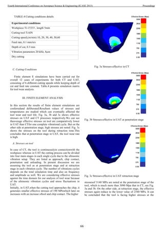
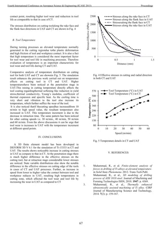

![Metamaterials in Aerospace Industry: Recent
Advances and Prospects
Rabia Zafar, Saima Shabbir
Institute of Space Technology, Islamabad,
Pakistan
drsaimashabbir@gmail.com
rabiazafar38@gmail.com
Azeem Zafar
National University of Science and Technology, Islamabad,
Pakistan
azeemgeologist@gmail.com
Abstract— This article offers a review of the existing
metamaterials and their concepts, recent advances, and research
directions. It also describes applications of metamaterials design
in aerospace and defense sector as an emerging technology.
Acoustic metamaterials and metamaterial based antenna present
advantages over conventional noise absorbers and antenna
technology employed in aerospace components. Gain
enhancement of antennas and efficiency of structures are
described in this article with reference to improvements and
advancements made so far in academia. A rational approach to
metamaterials science and engineering can revolutionize
aerospace design and render better prospects for military
applications.
Keywords—Acoustics, Aerospace, Metamaterials
I. INTRODUCTION
For the past few decades research in metamaterials is
gaining an increasing interest [1, 2] due to counterintuitive
electromagnetic properties incorporated into material
structure. Principally, Metamaterials are left handed
materials which exhibit negative refractive index, unusual
diamagnetic properties, with fractional effective
permeability and a very large in-plane effective permittivity
[3, 4]. The permeability can be attributed to the Eddy
current phenomenon induced in conductive inclusions and
permittivity is attributed to an increased value of dielectric
constant.
For a material to be optically transparent, the incident
wavelength will be refracted off centre the superficial
surface. The angle of refraction is smaller than angle of
incident as demonstrated in Fig. 1. The velocity of incident
wavelength is greater in space than the velocity of
transmitted wavelength [5] and object will appear
transparent.
Metamaterials find immense applications in the field of
science and engineering including wireless communication,
bio sensing, seismology, electromagnetic devices and perfect
lenses [6]. Moreover, metamaterial absorbers and emitters,
super lenses and cloaking devices for military camouflage are
under high consideration.
A. Development history
Developmental history of metamaterials began by 20th
century in 1904, when experiments on negative group
velocities were carried out by Pocklington [7] and progressed
through the mid of 20th
century contributed by distinguished
scientists [8, 9]. John Pendry in 1990’s made significant
contributions in the development of metamaterials theory [6].
Metamaterials do not exist naturally with the exception of
metallic element Bismuth. Plasmas and noble metals show this
behavior in infra red or visible spectrum [10].
B. Existing metamaterials
Metamaterials cover a narrow range of wavelength owing
to the fact that they can respond below red region of visible
wavelength. Based upon the medium properties, metamaterials
can be classified as;
• Negative index metamaterials (NIM) which include
double negative (DNG- ε and µ are negative) and
single negative metamaterials (SNG-either ε or µ is
negative),
• Double positive (DPS- ε and µ are positive),
• Epsilon negative (ENG- ε is negative and µ is
positive) and µ negative (MNG ε is positive and µ is
negative). MNGs show magneto optic effect in which
electromagnetic wave propagation takes place in a
quazistatic altered magnetic field [11].
Based on the response to a particular wavelength
metamaterials are further classified as photonic metamaterials,
acoustic metamaterials, seismic metamaterials,
electromagnetic metamaterials, terahertz metamaterials,
tunable metamaterials, elastic metamaterials, chiral
metamaterials and quantum metamaterials.
69
Fourth International Conference on Aerospace Science & Engineering (ICASE 2015) Proceedings](https://image.slidesharecdn.com/conferenceproceedingsicase2015final1-160918062150/85/Conference-proceedings-78-320.jpg)
![Fig. 1. Ray diagram of a metamaterial and a conventional material
II. MICRO FABRICATION AND APPLICATIONS
Metamaterials industry is emerging as a leading
technology in future for defense and aerospace sectors by
2020. Currently, there are only few methods available for the
fabrication and characterization which involve complex
principles of microelectronics and lithographic deposition.
The characterization of metamaterials is rather expensive,
which poses high need for capital investment in
instrumentation. Due to these limitations there are only a few
metamaterials which show negative effective permeability and
large permittivity and successfully characterized as
metamaterials.
A. Polymer based metamaterials
Metamaterials are composed of polymer matrix filled with,
copper, gold or silver flakes. They are formed by stacking
alternating layers of ENGs/MNGs type of metamaterials
separated by space.
Metamaterials for interference shielding applications were
fabricated by pulsed current electrolysis routes and by
carefully controlling the concentration of copper metal flakes
as inclusions in polymer matrix composites [12].
B. Metamaterial coatings
Metamaterials multipole coatings are being applied by
carefully tailoring the surface properties ranging from the
lowest ordered multipole coatings for microscopic bodies to
higher ordered multipoles for macroscopic bodies. Concealing
a macroscopic body becomes more difficult as domain size
increases and concealing the particles in a closed proximity is
difficult to achieve practically.
C. Metamaterial emitters
In a single band metamaterial a noble metal such as gold or
silver is deposited by electron beam lithography on a silicon
substrate followed by curing the spun coated
benzocyclobutene on metallic top. Dual band absorber is
fabricated by lithographic deposition with only difference that
the dielectric space is occupied by Al2O3. Such emitters find
applications in energy harvesting devices [13].
D. Metamaterials and seismic cloak
The seismic wave guided metamaterials can be made by
stacking sequences of macromolecular polymer based split
ring resonators overlaid with other meta atoms in a
consecutive fashion. Such a metamaterial can be used to
absorb seismic waves generated by earth quake and can
efficiently refract back or absorb seismic waves protecting
building infrastructure.
E. Stealth applications
Implementation of metamaterials in stealth technology
finds its use to disguise moving bodies from radar detection;
either by absorbing or by scattering all the radiations from the
radar detection system.
F. Acoustic cloaking
Acoustic metamaterials are ordered artificial structures
which can absorb and manipulate sonic, infrasonic and
ultrasonic waves at will [14]. Bulk modulus and mass density
counteract with permittivity and permeability. This analogous
property is under high consideration and research is being
done to direct and control sound waves at will by tailoring
these two parameters. 2D acoustic cloaking has been
optimized by placing five arrays of cylindrical lattices along a
common central axis to achieve omnidirectional cloaking
devices.
G. Metamaterials antenna gain
Metamaterials are being extensively studied to find
applications in wireless communication and improved antenna
performance i.e. gain enhancement, miniaturization of size,
directivity and bandwidth broadening. Antenna is dispersive in
nature and acts as an electrically small resonator. In a
conventional antenna surface waves propagate to increase
cross polarization effects, low gain, narrow bandwidth and
frequency range.
The quest continues as how to improve the output of
conventional antenna by incorporating metamaterial and
which particular type of metamaterial can improve one or
more parameters? An important consideration to achieve
antenna gain is to incorporate double negative DNG
metamaterials and single negative metamaterials into antenna
structure to harvest efficient yield and enhanced bandwidth.
SNGs are dispersive in nature [15]. Using this principle
behavior SNGs can be alternated with either MNG layer or
ENG layer to get a suitable combination of optical properties,
enhanced dispersion and miniature antenna size.
Finally, to reduce surface wave propagation it is necessary
to minimize the size of antenna and for this purpose photonic
band gap metamaterials can be employed.
III. Discussion and outlook
The demonstration of recent advancements and analysis of
metamaterials with all possible applications and future
prospects in both academia and industry is interesting. Various
antenna parameters have been studied and improved by
Metamaterial
Conventional
materials
Incident ray
70
Fourth International Conference on Aerospace Science & Engineering (ICASE 2015) Proceedings](https://image.slidesharecdn.com/conferenceproceedingsicase2015final1-160918062150/85/Conference-proceedings-79-320.jpg)
![different researchers such as gain enhancement, dispersion,
and bandwidth broadening and miniaturizing the size. Studies
revealed that unit cell metamaterials of omega structure can be
combined to form a slab and used to cover antenna surface
and increases directive gain to 11.5 dBi [16].
Metamaterial based broadband antenna were demonstrated
to show -1 dBi antenna gain at frequency of 2.5 GHz. with -1
dBi [17]. Electrically small antenna were demonstrated by
combining layers of ENG metamaterials alternated with
ordered multipole resonant structures to increase radiation
efficiency and high impedance [18].
Metamaterials show exceptional physical properties which
are overwhelming from both theoretical and academic
perspective and definitely find relevance to aerospace and
defense applications.
A. Metamaterial airborne design
In any purposeful review the electromagnetic properties of
metamaterials, which strongly impinge airborne radome
design cannot be neglected. Overall antenna performance is
strongly dependent on the mechanical and electromagnetic
properties of dielectrics. Unfortunately, there are limited
number of materials which compromise over low dielectric
constant and high mechanical strength. Significant research in
the radome design is necessary in both spheres of
metamaterials design and electromagnetism to circumvent
radome, which may pose restrictions in metamaterials airborne
design in near future.
An outlook of current projects shows that the developed
nations are involved in understanding the metamaterial
concepts and their practical applications. For example, BAE
systems has tested metamaterial based invisible vehicles
which can disguise in infra red and microwave frequency
range. Other international research groups are aiming at
developing nano sized plasmonic devices [19].
U.S. Army Research office in collaboration with university
students is developing liquid crystals tested in the range of 1-
110GHz. Other tunable devices made by liquid crystals are in
the process of development such as tunable antenna [20].
IV. FUTURE CHALLENGES
To address the future challenges metamaterials research
must transcend the theoretical investigations and transform
into practice. Practical applications make transitions through
terahertz (THz), infra red and visible region of
electromagnetic spectrum. THz metamaterials can be tailored
by changing meta atoms at nanoscale and open new horizons
of understanding and research in photonics and electronic
band gap materials. Challenges related to efficiently
generating and detecting broadband THz waves has primarily
limited their use. Currently existing metamaterials respond to
a narrow band of EM spectrum below red region of visible
spectrum. This requires the development of metamaterials to
extend their response in visible, micro and radio wave region
of EM spectrum in both theory and practice. Thus
metamaterials design can miniaturize antenna design [22] and
dispersion coupled with improved satellite communication and
can revolutionize the defense system.
V. SUMMARY
In this review we have taken a brief outlook of existing
metamaterials, their fabrication routes, current projects and
ongoing research to enhance performance and applicability of
metamaterial devices around the world. Survey of
metamaterials clearly demonstrated that metamaterials can be
used for improving the performance of conventional antennas
and can revolutionize the communication system.
Additionally, a brief review of the current work and
development in the field of metamaterials is provided. We also
examined the on-going projects on metamaterial to enhance
the performance of antennas and various novel metamaterials.
Various future challenges are also considered.
ACKNOWLEDGMENT
Authors would like to acknowledge Department of
Materials Science and Engineering, Institute of Space
Technology, Islamabad for encouragement and moral support
to write this review paper.
REFERENCES
[1] A. J. Hoffman, L. Alekseyev, S. S. Howard, K. J.
Franz, D. Wasserman, V. A. Podolskiy, E. E.
Narimanov, D. L. Sivco, and C. Gmach, “Negative
refraction in semiconductor metamaterials,” Nat.
Mater, vol. 6, pp. 946-950, October 2007.
[2] N. Fang, D. Xi, J. Xu, M. Ambati, W. Srituravanich,
C. Sun, and X. Zhang, “Ultrasonic metamaterials
with negative modulus,” Nat. Mater, vol. 5, pp. 452-
456, April 2006.
[3] R. A. Shelby, D. R. Smith, S. Shultz, and S. C.
Nemat-Nasser, "Microwave transmission through a
two-dimensional, isotropic, left-handed
metamaterial," Appl. Phys. Lett. vol. 78, pp. 489-491,
January 2001.
[4] D. R. Smith, W. J. Padilla, D. Vier, S. C. Nemat-
Nasser, and S. Schultz, "Composite Medium with
Simultaneously Negative Permeability and
Permittivity". Phys. Rev. Lett, vol. 84, pp. 4184-
4187, May. 2000.
[5] K. Sanderson, “Materials science: Unexpected tricks
of the light,” Nature, vol. 446, pp. 364-365, March
2007.
[6] J. B. Pendry, “Negative refraction makes perfect
lens,” Phys. Rev. Lett., vol. 85, pp. 3966-3969,
October 2000.
[7] H. C. Pocklington, “Growth of a Wave-group when
the Group-velocity is Negative”, Nature, vol. 71, pp.
607-608, April 1905.
[8] L. I. Mandel’shtam, “Group velocity in a crystal
lattice,” Zh. Eksp. Teor. Fiz, vol. 15, pp. 475-478,
April 1945.
[9] V. G. Veselago, “The electrodynamics of substances
with simultaneously negative values of ε and µ,” Sov.
Phys., Usp, vol.10, pp. 509-514, February 1968.
[10]V. A. Podolskiy, L. Alekseev, and E. E. Narimanov,
“Strongly anisotropic media: The THz perspectives
71
Fourth International Conference on Aerospace Science & Engineering (ICASE 2015) Proceedings](https://image.slidesharecdn.com/conferenceproceedingsicase2015final1-160918062150/85/Conference-proceedings-80-320.jpg)
![of left-handed materials,” J. Mod. Opt, vol. 52, pp.
2343-2349, January 2005.
[11]Z. Qiu, and S. D. Bader, “Surface Magneto-Optic
Kerr Effect. Characterization of Materials,” 2nd ed.,
John Wiley & Sons, 2012, pp.1-10.
[12]P. Los, A. Lukomska, S. Kowalska, R. Jeziorska, P.
Zaprzalski, and J. Krupka, “Metamaterials based on
polymer dispersions of nanoparticles and particles of
copper obtained by cathodic current pulse
electrolysis.” Materials Science-Poland, vol. 29, pp.
35-40, March 2011.
[13]X. Liu, T. Tyler, T. Starr, A. F. Starr, N. M. Jokerst,
and W. J. Padilla, “Taming the Blackbody with
Infrared Metamaterials as Selective Thermal
Emitters,” vol. 107, pp. 045901-4, July 2011.
[14]C. Jo, J. Jeong, B. J. Kwon, K. C. Park, and I. K. Oh,
“Omnidirectional two-dimensional acoustic cloak by
axisymmetric cylindrical lattices,” Wave Motion, vol.
54, , pp. 157-169, April 2015.
[15]G. V. Eleftheriades, and K. G. Balmain, “Negative-
refraction metamaterials: fundamental principles and
applications.” 1st ed., Wiley-IEEE Press. 2005.
[16]A. S. Ahmad, O. Adib, J. J. Mohd, H. B. Noor, A. A.
Robiatun, and F. F. Mohd, “Small patch antenna on
omega structure met material,” Eur. J. Sci. Res. vol.
43, pp. 527-537, June 2010.
[17]M. Palandoken, A. Grede, and H. Henke, “Broadband
Microstrip Antenna with Left-Handed
Metamaterials,” IEEE Trans. Antennas Propag, vol.
57, February 2009.
[18]A. Erentok, and R. W. Ziolkowski, “Metamaterial
inspired Efficient Electrically Small Antennas,” IEEE
Trans. Antennas Propag, vol. 56, pp. 691-707, March
2008.
[19]J. B. Pendry, A. J. Holden, D. J. Robbins, and W. J.
Stewart, “Low frequency plasmons in thin wire
structures,” J. Phys. Condens. Matter, vol. 10, pp.
4785, June 1998.
[20]D. R. Smith, “Research group- Novel,
electromagnetic materials program,” January 2005.
72
Fourth International Conference on Aerospace Science & Engineering (ICASE 2015) Proceedings](https://image.slidesharecdn.com/conferenceproceedingsicase2015final1-160918062150/85/Conference-proceedings-81-320.jpg)
![Finite Element Simulation of Composite Body Armor
Numan Khan1
, Abdul Shakoor1
1
Dept. of Mechanical Engineering
University of Engineering and Technology,
Peshawar, Pakistan
Write2numan@gmail.com
Riaz Muhammad2
, Naseer Ahmed2
2
Dept. of Mechanical Engineering
CECOS University of IT & Emerging Sciences,
Peshawar, Pakistan.
Vadim V. Silberschmidt3
3
School of Mechanical and Manufacturing Engineering,
Loughborough University,
Loughborough, UK
Abstract—Finite element simulation of composite body armor
for impact loading conditions is presented in this paper. The
7.62 mm armor piercing projectile with the velocity of 800 m/s
is used for impacting on the target material. The numerical
model is developed in ANSYS AUTODYN using Johnson–
Cook material model for projectile and backing steel material.
The Johnson–Holmquist material model is used for ceramic
material. Different simulations are performed for different
configurations of composite materials and the results of
projectile velocity, kinetic energy, internal energy of target
plate and perforation time is obtained. Finite element
simulation of 6 mm ceramic backed by 2 mm steel plate has
shown full penetration of bullet while the other backed by 4, 6
and 8 mm respectively has prevented complete penetration.
The numerical results show that ceramic material is
responsible for breaking projectile tip and absorbing most of
the kinetic energy. The drop of about 66% in projectile kinetic
energy is observed with increase of backing steel by 2 mm.
Finally optimum ceramic/steel material thickness ratio of 1.5
with light weight is recommended for single body armor.
Keywords- Numerical simulation; Ballistic impact;
Projectile; Armor plate; Johnson–Cook material model;
Johnson–Holmquist model
I. INTRODUCTION
Ever since the discovery of metals and alloys, different type
of protection is made against the enemies attack for
arresting high-velocity projectiles impact by mankind [1, 2].
The development of light weight and effective body armor
is the need of the day due to the current law and order
situation in the world and particularly in Pakistan. For the
mobility of solders light weight efficient and cost effective
body armor is necessary to be developed. Most of the
ballistic materials shows nonlinear deformation and
dynamic behavior under impact loading [3]. Material
properties like strain, strain rate, materials hardening and
thermal softening play a vital role in the design process [2].
With the passage of time different researchers have
developed various ballistic resistive materials.
Normally single high strength metallic plates are used for
body armors. However, multi layered plate configuration
are often used to meet the design specifications which
cannot be fulfilled by metallic single plate. Zukas et al. [4]
studied that a thick uniform steel plate was more resistant
to hemispherical projectile than composite multi layered
target of identical thickness due to free slip between plates.
It was also observed that by increasing the number of plates
in multi layered target plate reduces its resistance, which is
much closed to the data obtained from the experiments of
Almohandes et al. [5]. A detailed analysis of ballistic
performance of composite and hybrid armor plates were
performed using ANSYS AUTODYN software by
Yohannes Regassa et al. [6]. Ceramic faced armor plate
was used for observation of critical penetration velocity,
which shows good agreement with experimental results.
Teng et al. [7] has presented the performance of composite
and single layered steel armor under ballistic conditions and
concluded that nose shape, velocity and mass of projectile
are the key parameters effecting body armor performance.
Similarly, the effect of nose shape and hardness on failure
mechanism of the armor is presented in [8]. Studies of H.
Kurtaran et al [9]. has shown full penetration of
semispherical nose shape projectile through 2mm thick steel
plate at velocity of 500m/s. However the backing of front
plate with a 20 mm thick plate of same material and two
plates at different orientation angle has prevented full
penetration. it was further observed that the results of
Johnson-Cook Material model are more accurate than the
plastic kinematic model for evaluation of the fracture
damage and thermal softening [9]. Various analytical
models have been developed by S. Feli [10]. To analyze the
performance of Alumina plate backed by composite
material made of Twaron fibers. During impact the
fragmentation of ceramic conoid from ceramic tile and
decrease in the semi-angle of ceramic decreases with
increase of initial velocity was absorbed. The research for
design of light weight and efficient body armor required
more efforts for further improvement to increase its safety,
performance and cost effectiveness.
The current study demonstrates the finite element
simulation of projectile piercing ceramic steel target armor.
For fragmentation, the ceramic plate is modeled with
Johnson-Holmquist model where brittle failure, strain rate
effect and enormous deformation are considered. While
backing steel is modeled using Johnson-cook model in
which strain rate hardening effects, thermal softening and
materials fracture are reflected [9].
73
Fourth International Conference on Aerospace Science & Engineering (ICASE 2015) Proceedings](https://image.slidesharecdn.com/conferenceproceedingsicase2015final1-160918062150/85/Conference-proceedings-82-320.jpg)
![II. FINITE ELEMENT MODELING
The performance of composite body armor under impact
loading is investigated by explicit finite element model
using ANSYS AUTODYN [11, 12]. To reduce the
computational cost a small circular element of diameter 60
mm is considered for analysis. Initially the thickness of the
target plate is kept constant to 6 mm whereas actual bullet
dimensions are used for bullet modeling in the current
analysis. For addressing the increase of damage effect of
bullet on target plate with decrees in distance, these
simulations are carried out at minimum possible distance.
Similarly for simulation of the actual phenomenon of AK-
47 bullet with velocity range of 720 to 750 m/s, the
projectile is fired with a velocity of 800 m/s and its
rotational speed is neglected in the current study. Finite
element model for different configurations of ceramic and
steel are modeled as shown in Table 2. The thickness of the
front ceramic material is kept constant to 6 mm while the
4340 steel of different thickness 2, 4, 6 and 8 mm are used
as a backing material. To complete the perforation of the
plate the total time of simulation is considered as 50 µs. the
3D model of target armor and 7.62 mm diameter projectile
are shown in the Fig. 1. In current study the simulations are
carried out on core i3 PC with 2.2 GHz processor. The time
taken by one simulation is about between 8 to 12 hours of
CPU time.
A. Finite element mesh
A 3-D finite element mesh for both target plate and
projectile is generated by using automatic mesh generation
feature in ANSYS workbench. As can be seen form Fig. 2
the mesh of inner region of plate is kept finer than outer
region. In the mesh the maximum aspect ratio is kept below
five. Both the bullet and plate are meshed with hexagonal
elements of different size between 0.5 to 1.5 mm. The total
number of elements for the projectile and armor are 148,000
including, 52,000 elements for projectile and 96,000 for
armor plate.
B. Material model
Based on the material characteristics different material
models are used for different materials in bullet impact
simulation [1] In the current study, Johnson-Holmquist
model represented by equation 1 [13] is used for the
ceramic materials. This model is representing relationship
between the intact and fractured strength, pressure and
volume. The various parameter of the model are presented
in Table.1.
[ ( ) ][ ] (1)
Where A, B, n, C are material constants and is
representing the normalized strength of material.
is the normalized pressure. The damage D can be represented
by equation 2.
∑
( )
(2)
Here the equivalent plastic strain increment and
is the increment in the volumetric compaction strain.
Fig. 1. 3D model of projectile and target armor plate
Fig. 2. The FE mesh details of projectile and target armor plate
Similarly, Johnson-cook material model is used for the steel
part of the armor. The main feature of the Johnson Cook
model is representation[14-16] of the yield strength of
materials on high strain, strain rate, temperature and material
hardening, and is represented by the equation 3 [17]:
( )( )( - ) (3)
Where A, B, C, n and m are constants and is representing
value of effective stress, is effective plastic strain, is
normalized effective plastic strain
The term can be defined as:
(4)
In which and are used for melting and room
temperatures, respectively. Similarly, the damage of element
in Johnson-cook failure model is given by
∑ (5)
Where shows the change of equivalent plastic strain and
is the strain at fracture. The term can be represented by
the equation 6.
[ ( )][ ][ ] ( )
74
Fourth International Conference on Aerospace Science & Engineering (ICASE 2015) Proceedings](https://image.slidesharecdn.com/conferenceproceedingsicase2015final1-160918062150/85/Conference-proceedings-83-320.jpg)
![Table. 1 Strength and failure data for SiC using Johnson-Holmquist model
[18]
Parameters Units Values
Density (g/cm3
) 3.215
Equation of State Data (Linear)
Bulk Modulus-A1 GPa 220
Strength Data
Modulus of Rigidity GPa 193
Elastic Limit (Hugoniot) GPa 11.7
Intact Strength Constant-S1 GPa 7.1
Intact Strength Constant-P1 GPa 2.5
Intact Strength Constant-S2 GPa 12.2
Intact Strength Constant-P2 GPa 10
Constant of Strain Rate-C None 0.009
Fracture Strength (Max)-Sfmax GPa 1.3
Constant of Failed Strength-σ None 0.4
Failure Data
Tensile Limit-T GPa -0.75
Constant of Damage- Efmax None 1.2
Constant of Damage- P3 GPa 99.75
Constant of Buckling-β None 1
The fracture constants are expressed by D1, D2, D3, D4
and D5. For describing the pressure volume relationships
Mie–Gruneisen equation of state is used with combination of
Johnson-cook model [9]. Constant for Johnson-cook model
and Mie–Gruneisen equation of state model are given in
Table 3.
III. RESULTS AND DISCUSSION
Results of finite element simulation for projectile velocity of
800 m/s and different configurations as shown in Table.2 are
discussed in this section.
The variation in bullet velocity during penetrations for
different configurations is shown in Fig. 3. The config 1, 2
and 3 has maximum residual velocities of about 580 m/s,
230 m/s and 80 m/s respectively after impact while in config
4 projectile has been stopped and velocity is reached to 0 m/s
at 50 µs. this shows that the percent reduction in projectile
velocity is about 60% with the increase of backing material
thickness by 2 mm. this reduction is mainly due to the
impact of projectile on ceramic front material.
Table. 2 Composition and areal density for configuration of ceramic and
4340 steel plate
Configuration Front
SiC plate
Backing steel
plate
Areal density
(kg/m2
)
Config 1 6 mm 2 mm 34.99
Config 2 6 mm 4 mm 50.69
Config 3 6 mm 6 mm 66.39
Config 4 6 mm 8 mm 82.09
Fig. 3. Variation in projectile velocity
In the same way the Fig .4 gives the dissipation of kinetic
energy for config 1 to 4 after impact of projectile. It is
observed that maximum amount of kinetic energy is
dissipated in ceramic fragmentation and the rest of residual
kinetic energy is observed by the backing steel plate. The
config 4 dissipates maximum amount of energy as compared
to others as it goes through ceramic material. The percent
reduction in kinetic energy is about 66 % with increase of
thickness by 2 mm of backing material. This discloses that
the backing steel plate is responsible for absorption of
residual kinetic energy of the projectile and stop penetration.
Fig. 4. Projectile kinetic energy
The variation in internal energy of target armor plate can be
observed form Fig .5 which shows the increase for different
configurations. The Fig. 5a to Fig. 5d reveals that in all cases
the maximum amount of increase in internal energy of
ceramic plate is occurred. It is also observed that the increase
in internal energy of ceramic front plate is about 20 % with
increase of backing plate thickness by 2 mm. Similarly the
maximum increase in average internal energy is observed in
config 4 as shown in the Fig. 5. Thus by increase of backing
75
Fourth International Conference on Aerospace Science & Engineering (ICASE 2015) Proceedings](https://image.slidesharecdn.com/conferenceproceedingsicase2015final1-160918062150/85/Conference-proceedings-84-320.jpg)
![plate thickness maximum amount of kinetic can be absorbed in target armor plate. .
Table.3 Johnson- Cook model constants for 4340 steel[19]
Density, ρ (g/cm3
) Elasticity modulus, E (MPa)
Strength / Damage constants
A
(MPa)
B
(MPa)
N c m
7.83 210000 910 586 0.26 0.014 1.03
Failure Constants
D1 D2 D3 D4 D5
-0.8 2.1 -0.5 0.002 0.61
Mie–Gruneisen equation of state constants
Γ0 C1 (m/s)
1.6 3574
S1
1.91
Ref.
Temp
(K)
293
Fig. 5. Change Internal Energy for (a) Config 1, (b) Config 2, (c) Config 3, (d) Config 4
76
Fourth International Conference on Aerospace Science & Engineering (ICASE 2015) Proceedings](https://image.slidesharecdn.com/conferenceproceedingsicase2015final1-160918062150/85/Conference-proceedings-85-320.jpg)
![Similarly Fig. 6. shows the bullet penetration for
configuration 1 to 4. The config 1 shows full penetration of
bullet at velocity of 800 m/s whereas in config 2 the
penetration is stopped moderately. However, the bullet is
fully stopped by increasing the backing material thickness as
shown in config 3 and 4 in Fig. 6. Throughout the
simulations the damage mechanisms are observed in the
armor materials.
Firstly, Silicon carbide material which is very brittle tends to
shatter upon impact. It is also observed in the simulations
that the cause of failure of silicon carbide is tensile stress
wave that passes through the ceramic. Secondly, the tip of
the projectile become blunt upon impact with ceramic
material and adopted the shape like mushroom as shown in
Fig. 7. The distortion in projectile shape is increasing with in
increase in thickness as clear form Fig. 7. Another important
point is the deceleration of projectile upon advancement in
ceramic material. This reveals the fact that ceramic material
is contributing mainly in the breaking of projectile tip and
kinetic energy absorption. Finally the areal density for
different configuration is listed. Areal density can found by
adding the multiplication of the density and thickness values
of ceramic and backing steel material [1]. Upon comparison
with steel body armor of thickness 25.4 mm, about 100 kg
per square meter can be reduced. Thus reducing the total
weight can greatly improve the mobility of soldiers.
Config1Config2Config3Config4
t=0 µs t=10 µs t=20 µs t=30 µs t=40 µs t=50 µs
Fig. 6. Bullet penetration for different configurations at different time
77
Fourth International Conference on Aerospace Science & Engineering (ICASE 2015) Proceedings](https://image.slidesharecdn.com/conferenceproceedingsicase2015final1-160918062150/85/Conference-proceedings-86-320.jpg)
![Fig. 7. Bullet shape at 50 µs after impact on target armor plate
IV. CONCLUSIONS
In this work light weight ceramic composite body armor
is analyzed for impact loading of AK 47. A composite
material composed of Silicon Carbide and 4340 steel is
suggested and is simulated for various thicknesses. Based on
the simulation results, maximum reduction in kinetic energy
and increase in internal energy with increase of backing plate
thickness, the final optimum thickness ratio of 1.5 for
ceramic/4340 steel configuration is suggested.
It was also concluded that by reducing the thickness of
the backing materials can significantly reduce the weight of
the body armor, improve strength and will make it easy for
the security forces to carry it. As clear form table. 2 the
weight of about 15 kg per square meter can be saved if 2 mm
less thickness is used for backing material.
V. ACKNOWLEDGMENT
The authors would like to gratefully acknowledge Dr.
Rizwan Alim Mufti (Head of the Department) Pakistan
Institute of Engineering and Applied Sciences (PIEAS) for
his help in simulations.
VI. REFERENCES
[1]. Grujicic, M., et al., A computational analysis of the
ballistic performance of light-weight hybrid composite
armors. Applied Surface Science, 2006. 253(2): p. 730-
745.
[2]. Lee, M. and Y. Yoo, Analysis of ceramic/metal armour
systems. International Journal of Impact Engineering,
2001. 25(9): p. 819-829.
[3]. Børvik, T., S. Dey, and A. Clausen, Perforation
resistance of five different high-strength steel plates
subjected to small-arms projectiles. International Journal
of Impact Engineering, 2009. 36(7): p. 948-964.
[4]. Zukas, J.A. and D.R. Scheffler, Impact effects in
multilayered plates. International Journal of Solids and
Structures, 2001. 38(19): p. 3321-3328.
[5]. Almohandes, A.A., M.S. Abdel-Kader, and A.M.
Eleiche, Experimental investigation of the ballistic
resistance of steel-fiberglass reinforced polyester
laminated plates. Composites Part B: Engineering, 1996.
27(5): p. 447-458.
[6]. Regassa, Y., G. Likeleh, and R. Uppala, Modeling and
Simulation of Bullet Resistant Composite Body Armor.
[7]. Teng, X., T. Wierzbicki, and M. Huang, Ballistic
resistance of double-layered armor plates. International
journal of impact engineering, 2008. 35(8): p. 870-884.
[8]. Corran, R., P. Shadbolt, and C. Ruiz, Impact loading of
plates—an experimental investigation. International
Journal of Impact Engineering, 1983. 1(1): p. 3-22.
[9]. Kurtaran, H., M. Buyuk, and A. Eskandarian, Ballistic
impact simulation of GT model vehicle door using finite
element method. Theoretical and Applied Fracture
Mechanics, 2003. 40(2): p. 113-121.
[10]. Feli, S. and M. Asgari, Finite element simulation of
ceramic/composite armor under ballistic impact.
Composites Part B: Engineering, 2011. 42(4): p. 771-
780.
[11]. Fawaz, Z., W. Zheng, and K. Behdinan, Numerical
simulation of normal and oblique ballistic impact on
ceramic composite armours. Composite Structures, 2004.
63(3): p. 387-395.
[12]. Sadanandan, S. and J. Hetherington, Characterisation of
ceramic/steel and ceramic/aluminium armours subjected
to oblique impact. International journal of impact
engineering, 1997. 19(9): p. 811-819.
[13]. Johnson, G.R., Numerical algorithms and material
models for high-velocity impact computations.
International Journal of Impact Engineering, 2011.
38(6): p. 456-472.
[14]. Muhammad, R., et al. Effect of cutting conditions on
temperature generated in drilling process: A FEA
approach. in Advanced Materials Research. 2011. Trans
Tech Publ.
[15]. Muhammad, R., et al. Finite-element analysis of forces
in drilling of Ti-alloys at elevated temperature. in Solid
State Phenomena. 2012. Trans Tech Publ.
[16]. Muhammad, R., et al., 3D modeling of drilling process
of AISI 1010 steel. Journal of Machining and Forming
Technologies ISSN, 2010. 1947: p. 4369.
[17]. Zukas, J.A., High velocity impact dynamics. 1990:
Wiley-Interscience.
[18]. Holmquist, T.J. and G.R. Johnson, Response of silicon
carbide to high velocity impact. Journal of applied
physics, 2002. 91(9): p. 5858-5866.
[19]. Holmquist, T.J., D.W. Templeton, and K.D. Bishnoi,
Constitutive modeling of aluminum nitride for large
strain, high-strain rate, and high-pressure applications.
International Journal of Impact Engineering, 2001.
25(3): p. 211-231.
78
Fourth International Conference on Aerospace Science & Engineering (ICASE 2015) Proceedings](https://image.slidesharecdn.com/conferenceproceedingsicase2015final1-160918062150/85/Conference-proceedings-87-320.jpg)
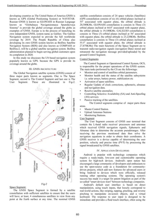
![vibration capabilities of the device to provide haptic feedback
to the user. Internal hardware such as accelerometers,
gyroscopes and proximity sensors are used by some
applications to respond to additional user actions, Android
devices boot to the home screen, the primary navigation and
information point on the device, which is similar to the desktop
found on PCs. Android home screens are typically made up of
app icons and widgets; app icons launch the associated
applications, whereas widgets display live, auto-updating
content such as the weather forecast, the user's email inbox, or
a news ticker directly on the home screen. Third-party apps
available on Google Play and other app stores can extensively
re-theme the home screen, and even mimic the look of other
operating systems, such as Windows or IOS.[59] Most
manufacturers, and some wireless carriers, customized the look
and feel of their Android devices to differentiate themselves
from their competitors.
Various types of Application developer suits are used in
market but Software Development Kit (SDK) is the famous
platform to use for application development in android based
operating devices.
App Work Flow
To develop apps for Android, you use a set of tools that are
included in Android Studio. In addition to using the tools from
Android Studio, can also access most of the SDK tools from
the command line. Developing with Android Studio is the
preferred method because it can directly invoke the tools that
need while developing applications.
However we choose to develop with another IDE or a
simple text editor and invoke the tools on the command line or
with scripts. This is a less streamlined way to develop because
you will sometimes have to call command line tools manually,
but you will have access to the same number of features that
you would have in Android Studio. The basic steps for
developing applications (with or without Android Studio) are
shown in Fig-3. The development steps encompass four
development phases, which include:.
A. Environment Setup
During this phase installed and set up development
environment. And also create Android Virtual Devices (AVDs)
and connect hardware devices on which install the
development applications.
B. Project Setup and Development
During this phase we set up and develop Android Studio
project and application modules, which contain all of the
source code and resource files for designed application.
C. Debugging and Testing
During this phase build an application into a debug
able .apk packages that can install and run on the emulator or
an Android-powered device. Android Studio uses a build
system based on Gradle that provides flexibility, customized
build variants, dependency resolution, and much more. If using
another IDE, build an application using Gradle and install it on
a device using adb. Next, with Android Studio debug
application using the Android Debug Monitor and device log
messages (logact) along with the IntelliJ IDEA intelligent
coding features. We can also use a JDWP-compliant debugger
along with the debugging and logging tools that are provided
with the Android SDK. And an Last, test your application
using various Android SDK testing tools. For more
information, see Test your application with the Testing and
Instrumentation framework
Fig-3
D. Publishing
Publishing is the general process that makes your
Android applications available to the users. When you publish
an Android application you perform two main tasks:
Prepare the application for release.
During the preparation step you build a release version of
your application, which users can download and install on their
Android-powered devices.
Usually, release application through an application
marketplace, such as Google Play. However, we can also
release applications by sending them directly to users or by
letting users download them from your own website.
V. PROPOSED APPLICATION
Few years earlier the firms have no choice to manage &
update changes their area maps by timely surveying. The
rescue response on various emergency conditions response
teams are managed by the area an number of rescue stations are
managed regain, City and country because no one knwn the
batter location of the area maps and totally dependent by the
information that provided by the caller, the caller informed the
condition of emergency and inform his location too, the call
receiver/operator note down information and pointed the
position on given map and then lookout the nearest rescue
operation and mobilized them towards effected areas or parties.
The mention procedure required much time to evacuate the
81
Fourth International Conference on Aerospace Science & Engineering (ICASE 2015) Proceedings](https://image.slidesharecdn.com/conferenceproceedingsicase2015final1-160918062150/85/Conference-proceedings-90-320.jpg)
![effected partied from effected place. Since 1992 the first GNSS
is lunched worldwide by Unites States department of defense
knows as Global Positioning System (GPS), this system is
designed for military requirement but the system provides the
navigation information round the clock globally with low
accuracy for civilian users. Initially the GPS receivers huge in
size and quit expensive, Now days the receivers are available
in reduces in sizes and the decreases the price too. The reduced
size receiver are used/ installed in the smart devices i.e. cell
phones, tablets, wrest watches etc.
as on proposed work the main aim is build up an
android based application, that’s incorporate the GNSS,
android & Cellular Communication to reduced the time for
rescue/ emergency relief operation by fixing the exact position
of the effected place or parties to save lives and also save them
resources.
A. Application Flow
The android application functional block diagram is shown
in the Fig-4, the functional diagram is operational when the app
is installed on the android based smart device either it’s a cell
phone or the tablet/PDA, whatever its brand but must have a
GNSS receiver, now days devices have GPS/ GLONASS
supported receivers.
Start
Direct Launched
Launched by Dialed
Numbers
Enable GNSS
Receiver
Determine Position
with time
Position Fixed
Determine Position
with time
No
YES
Position
Stored
Sending
Source
Generation
.nav
Extention
InternetSMS
Sent to Destination
Server Via Internet
Sent to Destination
Server Via SMS
Displayed Message
“Position Sent”
End Process
Standby mode
Repeat loop
3 times
Disable GNSS
Receiver
Fig-4
After the installation is done on a device either it’s a cell
phone or tablet. The application is standby mode because the
power is important factor in the smart devices.
The application is lunched by the App icon at app manager
screen or by dialed fixed or predefined number patters i.e.
1122, 115 & 114 etc. The application starts and performed its
initial operation that is the enable the GNSS receiver, in this
step the physical GNSS receiver is power on and a popup on
the screen the GPS enables.
In the next block is performed operation i.e. tracked the
presented satellites (4 signals) over the sky, and compute its
position, this process take some time up 30 seconds initial for
position fixation. It performed frequently operations until the
position is fixed. In next step, but it’s performed the parallel
with previous one (position fixing), its desired the information
from the user (depend on the user of application i.e. courier
services, vaccinations, the community health programs or
emergency Search and rescue relief operation) Information
competed with coordinates, now the information is saved at
local storage with automatically generated label (either its date
with time or with number series). The stored information is
may be required to be converted on the required format (i.e.
.nav, .txt or .ext etc extension files or nay other format
according to the requirement) and also added the cell phone
number for easy identification of the position, after suitable
conversion and addition in the file, the information is ready to
send their central information center using the internet or the
SMS, tasks is repeated at three times in four minutes for better
position for rescue operations. Once the task is complete the
user can disconnect the call the application is automatically
disabled the gnss receiver and goes to standby mode.
CONCLUSION
Currently, GNSS resources are available freely without any
cost and GNSS market is growing quickly and has been
expanded in vast areas of applications. Nowadays, GNSS
receivers are installed in wrest watches, phones, tablets,
satellites, aero planes and other communications devices.
Android has an open source code and resource and can easily
be integrated with GNSS. Applications for the local market can
be produced i.e. health, search and rescue will be improved and
enhanced in Pakistan.
ACKNOWLEDGMENT
I personally thank Dr Najam Abbass department of
aeronautics and astronautics institute of space technology
Islamabad, Pakistan for his kind effort for completion of the
research project and express my warm thanks to Mr. Hassan
Ali for his aspiring guidance, and sincerely grateful to them for
sharing their enlightening views on a number of matters related
to the project.
REFERENCES
1] HOANG, V. D., HA, D. T., & PHUONG, X. Q.
(2013). A Vehicle Monitoring and Navigation System Design
based on Android Smartphone (Space, Aeronautical and
Navigational Electronics).
2] Marti, E., Garcia, J., & Molina, J. M. (2014, July).
Navigation capabilities of mid-cost GNSS/INS vs. smartphone:
Analysis and comparison in urban navigation scenarios. In
Information Fusion (FUSION), 2014 17th International
Conference on (pp. 1-7). IEEE.
82
Fourth International Conference on Aerospace Science & Engineering (ICASE 2015) Proceedings](https://image.slidesharecdn.com/conferenceproceedingsicase2015final1-160918062150/85/Conference-proceedings-91-320.jpg)
![3] Djuric, U., Abolmasov, B., Dragana, P., Marjanovic,
M., & Kuzmic, P. PORTABLE GEOTECHNICS–USING
ANDROID SMARTPHONES AND TABLETS FOR
GEOTECHNICAL FIELD INVESTIGATIONS.
4] developer.android.com
5] http://en.wikipedia.org/wiki/
Android_(operating_system)
83
Fourth International Conference on Aerospace Science & Engineering (ICASE 2015) Proceedings](https://image.slidesharecdn.com/conferenceproceedingsicase2015final1-160918062150/85/Conference-proceedings-92-320.jpg)
![Geostatistical Analysis on Seismic Data over
North-Western Regions of Pakistan, Afghanistan
and Eastern Regions of Iran & Tajikistan
Malik Abid Hussain Khokhar1
, Asad Ali1
, Sadaf Javed1
& Razia Rani2
1
Department of Space Science, Institute of Space Technology, Islamabad 44000, Pakistan
1
abidmalikgeo@gmail.com, 1
asad06@gmail.com, 1
nomi4all786@gmail.com,
2
Department of Geography, Government College University, Lahore
2
raziaranigeo@gmail.com
Abstract – Earthquake, it is a process which usually take place
anywhere in the world. But most of the time this phenomena
takes place at the place which is weak part of the earth - faults.
Earthquakes occur where faults are but magnitude and depth
remain less at particular places. Factually, it is considered that
earthquake activity is normally related to particular activity of
tectonic processes under the earth. The Seismic geomorphic
structures contain particular basic source mechanisms and with
regard to seismic activity, these bases are considered as a solution
of tectonic regional planes. In this way, different seismic activities
solutions bind their strong dependence with a recognized fault
linage system. Furthermore, these connected seismic activities
give us benefits of attaining an objective of absolute possible
“depth and magnitude” of earthquake. The seism-o-tectonic
model is an essential parameter that covers the assessment of
earthquake activity. The tectonic framework of the said study
region is extended from the fault system on the west to northwest
Himalaya and boundary of Hindu Kush-Pamir terrain to the
seismic belt of the geographical borders of Pakistan, Afghanistan,
Iran and Tajikistan. Sequel to this, a geostatistical analysis are
conducted by utilizing variogram estimations, anisotropy and
kriging methods for seismic depth conversion and magnitude on
the said sub-surfaces and interval velocity fields in a dependable
way.
Index Terms— Geostatistics, Earthquake, Seismicity,
Magnitude, Variogram, Kriging.
I. INTRODUCTION
Earthquake take place in the faults areas where their
intensity increases if there is weak surface prevailed then it
bring about the source of a number of earthquakes as a natural
calamity. Various features of geology in the region are direct
manifestation of subsurface of the earth dynamics that’s why it
is important to understand variety of problem related to
physical endogenic processes aspects of happening deep down
the earth surface. Earthquakes create faulting and folding due
to above mentioned processes and bring about severe natural
disasters in the affected areas. These happened due to primary
and secondary and long waves that determined depth and
intensity of the earthquakes[1]. The area is extended to
Himalayan arc which encompass about 2,500 km from
northwest to southeast and includes from east to west the width
of the belt varies from 250-350 km. The colossal Himalayas
and the Karakoram, representing the biggest concentration of
lithospheric masses, grew south of the Pamir that goes to Iran
from touching southwestern parts of Pakistan and the western
regions of Afghanistan. The study area contains a captivating
geological record of Precambrian to present and terminate both
east and west with spectacular bends. The region covers the
foot hills, lesser Himalayas, Greater Himalayas and Higher
Tajikistan Mountainous Zones. Changes in the Earth's
orography and consequent geomorphic changes are directly
related to the ongoing seismic event. This collisional events
have long been argued to be liable for geological, geochemical
and seismic magnitudes of global extent[2]. The exogenic /
eperogenic processes are still going on with the approximate
rate of a few centimeters per year imperceptibly with continued
erosional and denudation factors of internal movements. The
eroded material from its rugged topography is regularly shed
into different depositional settings within the Himalayas. In
this region, the stress and strain caused due to plate movements
which cause frequent earthquakes enormous loss of human life.
Landslides and irregular thrusting have been also cause of
frequent natural disasters. Deforestation and road construction
have also been witnessed as a reason of landslides. Earthquakes
occurred within the Baluchistan Range (Pakistan) and Iran
ranges with the Mw6.4 which generated a complex and poorly
located seismic sequence. These earthquakes mostly affected
Pishin and Ziarat districts along with the borders areas of Iran,
an area where several active faults have previously been
identified. To create the relationship between these earthquakes
variograms models have been established for geostatistical
analysis”[3]. In the paper, geostatistical analysis (variogram
estimations, anisotropy, kriging and cross validation) on Depth
and Magnitude of the earthquake data on the subject regions
are applied that display spatial structure ranges and directional
ranges.
II. DATA AND STUDY AREA
Borders of Pakistan, Afghanistan, Iran and Tajikistan are
the study area is chosen where earthquakes are frequent due to
weak subsurface. Area is bounded in between 230
.37’N to
410
N and 440
E to 790
E. The points in the map are showing the
number of earthquakes are frequent due to weak subsurface.
Area is bounded in between 230
.37’N to 410
N and 440
E to 790
E. The points in the map are showing the number of
earthquakes that occurred in between 2014 to March 2015.
84
Fourth International Conference on Aerospace Science & Engineering (ICASE 2015) Proceedings](https://image.slidesharecdn.com/conferenceproceedingsicase2015final1-160918062150/85/Conference-proceedings-93-320.jpg)
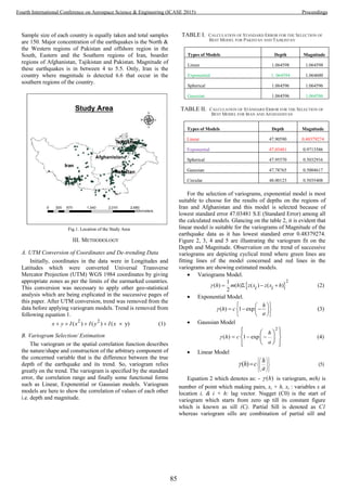
![nugget such as 0 1C C C . Nugget effect is minimized to
zero C(0). Owing to this condition, variogram is not enough for
spatial variation analysis & suitable model must be fitted on
it[4]. In the equation number 2, 3, 4 and 5 are known as the
models as mentioned against each. Here, ‘c’ is a Sill and ‘h’ is
lag specified from the distance/ weight derived from the
coordinates and given values at the coordinates.
C. Kriging
Interpolation provide Kriging methods besides Kernel
Density etc. In geostatistical methods, Kriging is also “Best
Linear Unbiased Predictor" (BLUP) which satisfies a certain
criterion and provide minimum variance[5]. The kriging is
based on the weighted moving average[6].
0
0
(6)
var
Z x Z xii
Z It is an estimated iable at the spatial location
x location
Z x observed parameter of Depth and Magnitudei
every predicted form nearest neighbore of spatial
points
weights applied to these neighboring po ts
a
i
t
in
Unity of sum is the weights are constrained so Equation 6 is
an unbiased estimator[7].
IV. RESULTS
Results in the successive pages are over the seismic data of
the study areas. After the application of various models of
variograms as per the appropriate requirement of model of the
variogram, Ordinary Kriging analysis are applied. It is because
of its real implementation and OK (Ordinary Kriging) is
appropriate applicable where spatial sampled data is large. This
method comprehensively evolves on sampled observations
instead of complete population where trend assessment of
spatial identity always re-assessed so that a smooth and
accommodative model may arise. For depth and magnitude
analysis, Ordinary Kriging (OK) remains always very suitable,
but it does not work properly if we have very small sample data
for using in moving neighborhood observations and so it bring
about the reason of further good and useful results[9]. The
results which showing the variograms are in cyclical with the
models of Exponentials, Linear and Gaussian. These were
derived on the basis of lowest standard that bring about the
enormous appropriate cause of validity of findings for any data
basing upon geostatistical methods. Results are restricted to
bifurcated due to large area and large sample size. Initially,
sample size of the data was accumulatively 600 which split to
two parts of 300 each. Data was full of trend which has been
shown in the variograms models and anisotropy plots. These
plots are derives from the R language and ArcGIS was also
incorporated for visual interpretations which has been useful to
predict the nearby areas by known points. By viewing, figures
12, 13, and 14 are predicting depth and magnitudes of
earthquakes by the application of Kriging and Kriging is found
the most suitable predictors because it is showing very accurate
results. For comprehensive geostatistical analysis,
omnidirectional variograms are not taken to compute the
directional trend in the data which require to analyze trend of
anisotropy in the sampled data. So sequel to these indicators
directional variograms are calculated with the angle tolerance
150
from 00
to 1650
. Figure 6 and 7 are interpreting anisotropic
trends as well as directional trend in the data for depth and
magnitude of seismic data on the subject regions, where point-
paired values are evidently displayed with respect to their
directions Finding enormous trend of direction, it is evident
that direction is not uniform to a specific side rather all sides
which depicts that compactness of the lithosphere which is not
too hard to sustain the shocks of frequent earthquakes that’s the
reason for tremendous isotropic trend. Beside these, another
way of determining said trend, there is a method of Rose-
Diagram that is used for computing anisotropy within the map
having 3600
angular direction, under mentioned figures are
related to said directional trend which are showing the
direction of earthquake magnitude and its depth in the subject
regions. With respect to different angels, an unequivocal
variation in the above shown rose diagrams of Pakistan &
Tajikistan Regions and Iran & Afghanistan regions. When the
data of Magnitude values and depth values of occurred
earthquakes of the subject regions are slanted in a side then
both plots show only that certain direction either 00
degree or
900
degree whereas the trends elucidate the level of depth in
different directions specified rocks of weaken lithosphere. For
comprehending the intensity of the depth and magnitude of the
earthquake, figure 6 and 7 exhibit variogram factor parameters
with all possible angles. Numerical figures of the said
variograms are showing directional variogram for relating
parameters of same dataset within anisotropic influence.
Magnitude and depth have different numbers of values in view
of the sill, partial sill and nuggets and range is comparatively
less differ in the whole dataset because these are based on the
Standard Error’s values which are being selected on the basis
of lowest vales and models are also applied on the
appropriations where Depths have 700 at 1500
and sill is 12000
that is the maximum figure in case of Pakistan and Tajikistan
regions and on the same angles Iran and Afghanistan have the
lowest observation at this angle but this regions has more than
6000 sill vales at 1180
and nugget values is 1500. Deviations
proceed to the resultant anisotropic effect in the data values.
Similarly, Magnitude data is of the both regions have different
sill effects, nugget and rang in terms of their direction
significances. Merely, directional variograms are not sufficient
for geostatistical analysis for computations for interpolation
methods like Kriging and Inverse Distance Weighted analysis
but other analysis of variograms are also needed to interpolated
directional ranges and anisotropic corrected variograms of
current data. Above discussed directional ranges are estimated
directional coverage of predicted surface areas along with
appropriate model fittings. Figure 14 is showing Kriging plot
of depth values of earthquake data in all the areas as mentioned
in topic and figure 13 is established using Geostatistical
Analyst Tool of ArcGIS. Figures 12 is serving a clear depiction
of variables Depth and Magnitudes of whole data set with the
86
Fourth International Conference on Aerospace Science & Engineering (ICASE 2015) Proceedings](https://image.slidesharecdn.com/conferenceproceedingsicase2015final1-160918062150/85/Conference-proceedings-95-320.jpg)


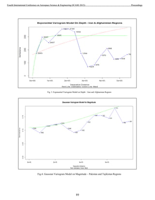
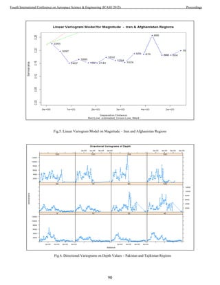
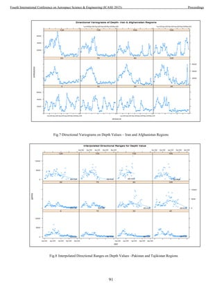
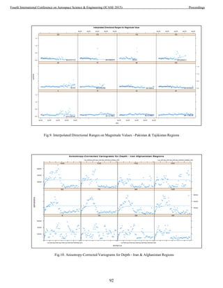
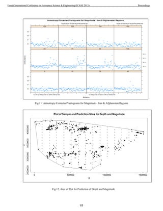
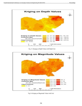
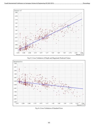
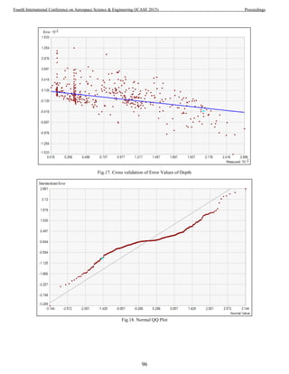
![V. ROSS VALIDATION
Cross-validation, it is also known as the appreciation with
the name of rotation estimation, that is a technique of model
validation to evaluate geostatistical analysis for generalization
of an independent dataset [10]. It is mainly used in settings
where the goal is prediction, and one wants to estimate how
correctly/ perfectly a predictive model to perform in practice
into implementations of cross validation. It is the tool of
computing the validation of correctness and authentication of
the methodology of geostatistical analysis like Kriging and
Kernel Density etc. It is important to mention over here that
the main reasons for using cross-validation instead of using the
conventional validation is that the error (e.g. Root Mean
Square Error) on the dataset. Because the conventional
validation is not a useful estimator of model performance and
thus the error on the observational dataset does not properly
represent the assessment of model performance[10]. This way
to tool is not only the part of geostatistics methods but also it is
a part of Geostatistical Analyst tool in ArcGIS. Sequel to this,
following are few plots which are derived from Geostatistical
Analyst Tool that includes predicted values, error, and standard
error and QQ plot. QQ plot is showing the distribution of
dataset. Figure 15 is the depiction of distribution of predicted
observations and the sample observations with their cross-
validation.
VI. CONCLUSION
On the subject topic of four countries (i.e. Pakistan, Iran,
Afghanistan and Tajikistan), six hundred sample points/
observations were collected and only three parameter are used
which are coordinates, magnitudes and depth of the
earthquakes. Geostatistical analysis are applied on these
parameters. With the help of R language, major geostatistical
analysis (variogram model analysis, anisotropic analysis and
Kriging etc.) are conducted; however ArcGIS is also
incorporated for visual interpretation with the utilization of
geostatistical analyst tools. Taking all the analysis methods on
board, it is concluded that Ordinary Kriging is the valid/ best
estimation method because it presents accurate smooth canvass
of surface and minimum standard error estimation as revealed
in cross validation plots and table number 3 and 4. For
correctness of the application of Kriging cross the validation on
depth and magnitude of earthquake data is carried out as well.
Seismic spatial point data are gigantic source of information to
see the location and concentration of earthquake where we can
estimate disaster damage which help us to layout decision
making efforts for benefiting mankind. Semi-variogram and
other variogram models analysis of seismic data are very
useful for estimating destructions and directions of waves of
earthquakes as showing in the figures 2,3,4, 5 and it is also
significant for direction of earthquakes. The paper has shown
that semi-variogram variables of range, nugget and sill which
can be easily used to pinpoint earthquake spatial deviation and
consequently the location of severely damaged areas as well.
Hence, it is concluded that Northeastern regions of
Afghanistan, Eastern regions of Tajikistan are major
concentrated areas of earthquake and more deepened than the
other regions of Pakistan and Iran. However, as for as
magnitudes of the earthquakes are concerned, eastern and east-
southern parts of Iran are very vulnerable due to weaken parts
of Lithospheric compactness which can give room for more
severe earthquakes with higher intensity of 6.6. Southern parts
of Pakistan with the borders of Iran and western Balochistan
are also vulnerable places for future earthquakes.
ACKNOWLEDGEMENT
The authors are indebted to Dr. Asad Ali who guided them
for writing this paper and he reviewed the paper as a whole.
His precious time from his busy schedule and commendable
cooperation is highly appreciable in conducting this research
work.
REFERENCES
[1] N. L. and T. M. Gary Mavko, “Seismic Methods For
Imaging Physical Properties of the Earth,” pp. 0–3, 1995.
[2] S. Development and I. M. Region, The Tajik Pamirs
Challenges of Sustainable Development in an Isolated
Mountain Region. .
[3] D. L. P. Parasad, Journal of Nepal Geological Society, vol.
45. .
[4] C. E. G. James, R., “Use Of Geostatistics For Accurate
Mapping Of Earthquake Ground Motion,” no. 1988, pp. 31–
40, 1989.
[5] V. De Rubeis, P. Tosi, C. Gasparini, and A. Solipaca,
“Application of Kriging Technique to Seismic Intensity
Data,” vol. 95, no. 2, pp. 540–548, 2005.
[6] M. Franklin, “Solution to Ordinary and Universal Kriging
Equations,” pp. 1–5, 2014.
[7] R. Giraldo, P. Delicado, and J. Mateu, “Geostatistics for
Functional Data : An Ordinary Kriging Approach.”
[8] K. Chang, Introduction To Geographic Information Systems,
Sixth Edit. Printed in Singapore: McGraw-Hill, 2012, p.
418.
[9] P. Abrahamsen, “GEOSTATISTICS FOR SEISMIC
DEPTH CONVERSION 3 . Kriging in the geophysical
literature 4 . Seismic depth conversion 5 . Velocity or depth
prediction 6 . Variogram estimation,” pp. 1–9, 1996.
[10] S. Geisser, Predictive Inference. Chapman and Hall, 1993,
p. 3471.
97
Fourth International Conference on Aerospace Science & Engineering (ICASE 2015) Proceedings](https://image.slidesharecdn.com/conferenceproceedingsicase2015final1-160918062150/85/Conference-proceedings-106-320.jpg)
![GIS for estimating optimized water demand using
sustainable water resource management for a planned
city
Rabia Tabassum,1,2
, Mudassar Hassan Arsalan2,3
, Arif Inam Osmani3
, Anam Khalid2
1
Science and Humanities Department
National University of Computer and Emerging Sciences (FAST),
Karachi, Pakistan
2
Geoinformaticsand Sustainable Development Research Lab
Institute of Space and Planetary Astrophysics, University of Karachi, Pakistan
3
Osmani & Company (Pvt.) Ltd., Karachi, Pakistan
.
Abstract
Water, a vital natural resource, is the topic of modern researcher and
getting momentum throughout the world due to its scarcity. Many
regions of the world have reached a point at which present water
resources are already being over-used, as indicated by the depletion
of groundwater aquifer and rivers which no longer to reach the sea.
The alternate water supply approach becomes more important to
achieve sustainable urban development and to reduce the energy as
well. The idea of using modern techniques like remote sensing and
geographical information systems (GIS) in water resource
management studies is quite mature. In the last two decades, RS and
GIS have been broadly used for the preparation of different sorts of
thematic layers and integrating them for multiple purposes,
especially for watershed analysis, ground water recharge and water
demand optimizations.
The DHA City Karachi (DCK), the study area, has been envisioned
as the first sustainable city of Pakistan which will probably serve as
a model for the future independent planned cities in the country and
abroad. The domestic water requirement of 54 gpcd has been
considered as a standard of Karachi Water and Sewerage Board for
the metropolitan city and average water demand per unit area is
calculated as 0.09 g/ft2
for DCK.
This study consists of two parts, in the first part water demand
estimation is done for the DCK land use; Residential, commercial,
Mixed use, Amenities, Recreation, Utilities, Transportation,
Agriculture farming and Reserved spaces. Water in gallon per capita
per day (gpcd) and gallon per unit area per day (gal/ft2
) are
considered as water coefficients for the water demand calculation.
DCK water demand on time scale is estimated as per its development
and inhabitation strategy, which is going to develop in three phases;
Short Term (2012-2015), Mid Term (2015-2020) and Long Term
(2020-2030).
Secondly, to estimate optimized water demand for the land use, the
most feasible and easy to deploy strategies and methods like
efficiency practices (behavior practice and Technology practices)
and gray water recycle and reuse is used. By implementing these
water reduction methods on DCK estimated water demand, it is
evident that recycling and reuse of waste water have a positive
impact on ecological sustainability.
Index Terms:
Water demand efficiency, Recycle and reuse of gray water, Water
demand, Alternate water resources, GIS.
I. INTRODUCTION
Water is one of the most vital natural resources that somewhat
different from the other, as it is viewed as a key to prosperity
and wealth. Water has played a crucial role in the growth,
function and location of communities[2]. Egypt, South Africa
and Pakistan are the most water-limited nation among the
twenty five most populous countries. According to the World
Bank data, Pakistan’s river system has a storage capacity of 30
days of water usage, India stores 120 days, while US stores
900 days of river water. In international and national agendas,
sustainable water policies search is at its peak. Approximately
40% of the world’s population will probably experience
shortages in water by 2050. When water could not find in the
desire quality and amount at the right place and time, water
problem may exist [3]. World’s arid and semiarid regions have
motivated the development of the innovative management
measures due to water shortage. At large, the major part of
Pakistan is arid and semi-arid, therefore water management
system improvement is necessary.
The systems to manipulate and present spatial data can be
considered as Geographical Information systems (GIS),
which are capable of performing a range of function such as
data capture, data storage, data cleaning, data finding and
retrieval, statistical and spatial analysis, and data display [4].
GIS applications as efficacious technology in water resources
management for storing, managing, displaying spatial data are
constantly raising. These applications, including supply and
sewer system modeling, surface hydrology and ground water
modeling, storm water and nonpoint source pollution
modeling for urban and agricultural areas. Because of the
spatial nature of the data for design, planning, operation and
maintenance of water and sewer system in urban areas, GIS
technology used for such systems to provide benefit
significantly. The unique characteristics like family size, lot
size, property value, and soil property, which vary from on
different geographical locations, are associated with
consumers that affect demand[5]. In hydrological modeling,
GIS could be useful to provide the information needed for a
watershed runoff analysis. The integrated technique using
98
Fourth International Conference on Aerospace Science & Engineering (ICASE 2015) Proceedings](https://image.slidesharecdn.com/conferenceproceedingsicase2015final1-160918062150/85/Conference-proceedings-107-320.jpg)
![GIS and physical based distributed hydrological models
considered as an effective technique in the field of watershed
–based water resource management[6].
II. LITERATURE REVIEW
In the last few decades, GIS use started to proliferate in the
field water resources management and planning. Mark R.
Leipnik and Hugo A. Loaiciga [7] discussed eachaspects of
GIS and focused on the other facets of GIS pertinent to the
planning and management of water resources. Geographical
Information Systems (GIS) have become an integral and
beneficial tool in many analyses such as statistical and spatial
analysis in water resources management [4, 8, 9].
Panagopoulos, et al. [10] estimated the future water
requirement based on population growth using multi-criteria
decision analysis in which Analytical Hierarchy Process
(AHP) and GIS techniques were involved. AHP has proved as
a useful tool for planners that assess future water demands and
it can be suitable for planning of a national water management
system.
Udovyk [11] ‘s research revealed that GIS couple with
modeling have potential to make a significant contribution to
integrated water resources management (IWRM) and also
notified the issue involved in using GIS as part of IWRM. GIS
considered as a powerful tool to interpolate and model the
spatial data, enable to overlay and compare the environment
and population data for quantifying the population at risk, and
also communicate these to decision makers and other
stakeholders[11].
A particular aspect of water resource management problems,
needs a specific approach to the development of GIS data
structure. By constructing a conceptual GIS data model to
integrate the physical and logical components of the modeling
problem into an operational framework, Daene C. Mc Kinney
[12] expended the function of GIS that implements a tight
linkage between Water resources management and GIS model
Ahmad [13] introduced a new approach for Simulation of
Water Resources Systems called spatial system dynamics
(SSD which presented for modeling feedback dynamics
processes in time and space. GIS and System dynamics are
couple to develop this model. In the study presented by Allen,
et al. [14], GIS is used for verifying and calibration a
continuous simulation model with an event –driven model;
they realized that GIS is useful in enhancing the modeling
efforts because of increased accuracy, and minimization of
human error with time.
One of the GIS application is future forecasting of water
demand, Shamsi [15] presented this application and
established the criteria for future development with the help of
potential development map, a digital elevation model, a
zoning map, and water ,sewer and road network maps. Same
works could be made for sewerage flows for the rapidly
growing population areas. For calculating and projecting the
average daily sewerage flows from the different land use such
as residential, commercial, and industrial, Kirshen [16] used
data handling properties of GIS.
For the development of a master plan of waste water system,
Giguere [17] used GIS and discovered its efficiency to bring
the relevant data from present databases into geographic
analysis environment, view information and, create report.
The master plan predicts future wastewater flows, assesses
existing treatment and collection system potential, constructs a
sewer rehabilitation program, assesses and identifies
alternatives to expand wastewater facilities, and makes a
phased plan to finance the required improvement. Moutal [18]
presented same work for different country. The automated
mapping system was used to record, update and database
development for planning, design and operations.
Domestic water demand considered as a complex element of
different factors, such as socioeconomic and physical
characteristics, urban planning strategies, infrastructure, and
public water policy. In GIS environment, different thematic
layers are used such as road network distance, distance from
the city center, distance from the coastline, topographic slope,
land use/land cover, Urban Plan, population density and
existing water supply and sewerage system that correspond for
the planning factors.
This study is basically for newly planned city and GIS tools
not only used for the master plan of the city, but also for
estimating water demand on spatial and temporal bases. The
main emphasis of the study is the estimation of optimized
water demand using sustainable water management approach.
III. STUDY AREA
DHA City Karachi (DCK) has been envisioned as “The First
Sustainable City of Pakistan”, which will serve as a model for
the future independent cities in the country and abroad. It is
with the aim to provide its citizens a safe, comfortable,
efficient, and beautiful lifestyle. DCK is strategically located
on the Karachi-Hyderabad Super Highway in District Malir at
the eastern border of Karachi as an independent urban center
in the vicinity of Karachi Metropolis. The city is planned on
an area spanning 11,668 Acres, comprising residential,
commercial and mixed-use elements.
In geographical characteristics topography and distances are
the main factors affecting the potential water sources. DCK is
naturally drained by Abdar and SukkanNullah (small non-
perennial water tributaries of Malir River). Their productive
aquifer is recharged from the same water streams and small
water reservoirs developed on them. It extends from latitudes
240 57 N to 250 2 N and longitudes 670 24’ E to 670 32’
E, and is a sub-tropical location in character.
The study area has a moderate climate and experiences bulk
rainfall in the duration of monsoon season, but the average
rainfall is recorded as only 7inches per annum. In summer,
May and June are the hottest months and temperature often
reaches the 43°C. January is considered as the coldest month
with temperature 5°C. As a part of Karachi district, DCK may
get its share of water from the bulk water supply by Karachi
99
Fourth International Conference on Aerospace Science & Engineering (ICASE 2015) Proceedings](https://image.slidesharecdn.com/conferenceproceedingsicase2015final1-160918062150/85/Conference-proceedings-108-320.jpg)
![Water and Sewage Board. But the current water budget of KW
&SB’s has been already in stress and demand is more than
supply.
A. DCK land Use Planning
The DHA City Karachi is the study area of this research and
Figure 1 shows its land use. For DHA city Karachi the entire
planning approach focuses on Sustainability Design
Principles, including the concepts of connectivity, efficiency,
renewability, minimization of externalities and carry
capacity[19]. These goals of sustainable design have been
adopted in the overall districts planning approach by
maintaining the ecological integrity of site nullahs, reserved
spaces and natural contours[20]. Master plan of DCK
cumulatively covers approximately 11,668 Acres of land and
comprises of eight major land use types as shown in Figure 2.
IV. METHODOLOGY
The basic aim of this study is the estimation of optimized
water demand by using alternate water resources for DCK in
GIS environment. For this purpose, the master plan of DCK
was converted into GIS format. ArcGIS software was used to
translate files from AutoCAD drawing files to the ArcGIS
shape file. The master plan of DCK was consisting of detailed
parcels/plots, transportation corridors, reserved spaces for
natural drainage, open and green spaces etc. Land use
classification was applied to parcels / plots, according to the
detailed master plan categories on different levels, such as the
major level comprised Residential, commercial, mixed use,
amenities, recreation, utilities, transportation, agricultural and
reserved spaces. The minor / detailed land use maps were also
developed for each individual major land use class according
to DCK planning. The flow chart of land use layer formation
is shown in Figure 3.
The water demand for DCK was calculated in the spatial
domain, on the basis of water in gallon per capita per day
(gpcd) and gallon per unit area per day (gal/ft2
), which was
measured according to the land use types. On a time scale
DCK water demand is estimated as per its development and
inhabitation strategy, which is going to develop in three
phases; Short-term, Midterm and Long-term. Sewage volume
is calculated, which gives the amount of water that can be
reused for the non-potable use. Also by implementing the
water reduction method such as efficiency practices and grey
water recycling, optimized water demand is estimated.
A. Criteria of Water demand estimation
According to United Nation, in 2012 approximately 50% of
the world's population lived in urban areas and this percentage
is expected to swell to 60 % by 2030[21]. Therefore, water
demand in commercial, domestic, and industrial areas are
consequently growing in cities and result the water
scarcity[22]. For newly planned city, water supply authorities
Figure 1: Study Area “DHA City Karachi with its land use
Figure 2: Land use types and % of Area of DCK
Figure 3: Flow chart of land use layers formation
100
Fourth International Conference on Aerospace Science & Engineering (ICASE 2015) Proceedings](https://image.slidesharecdn.com/conferenceproceedingsicase2015final1-160918062150/85/Conference-proceedings-109-320.jpg)
![are needed to supply water to their consumers with a certain
degree of reliability. Non uniform distribution of water will
cause water scarcity in some area and excess in other areas
which result the obstacle the natural growth of the city.
Therefore, proper criteria setting is necessary to know the
water demand in spatial and temporal domain instead of
computing demand as a whole which is the main objective of
this study.
Municipal water use commonly consists of residential,
industrial, commercial, and public uses, as well as some minor
use for other purposes like system losses, line cleaning and
firefighting. In developing countries public water withdrawal
is only 13-26 gpcd in contrast, many developed countries’
water withdrawal is 79-158gpcd. Municipal water demand is
exactly related to the amount of water withdrawn by
population in town, cities, housing estates, public and,
domestic service enterprises.
The public demand consumes high quality water from the city
water supply system and as its supply also includes water for
industry that provides directly for the requirements of urban
populations. The portion of municipal water demand that is
used in the home is the residential or domestic water demand
and worldwide typical domestic use of water in comparison
with residential plot of 500 square yards is given in Table 1.
This water use is highly dependent on socioeconomic and
environmental conditions and including toilet flush, bathing,
cooking, drinking, watering lawn, and other uses. The average
water demand varies from 25 to 120 gpcd whereas the most
commonly used range is 50-80gpcd for the world urban areas.
In many developed countries residential water use can
constitute over half of total municipal water use and
consumption. Residential water use is also directly linked to
the general public health. Improving the health of the poor is
one of the main goals of water and sanitation projects.
Therefore, household water use is always the top priority in
the municipal water supply[23].
Estimation of water demand based on per-capita consumption
is one of the common approaches. Karachi Water and
Sewerage Board is the main source of water supply for
Karachi city. DCK’s current estimated water demand stands at
45MGD. Initially the average domestic water requirement has
assumed as 54 gallons per capita per day for the DCK which is
a reasonable value in comparison with per capita daily water
demand for the different world cities, e.g. Tokyo –Japan
(77gpcd) New York-USA (161 gpcd) Colombo-Sri Lanka
(60gpcd) and Mumbai- India (43gpcd) [24].
Most of the people who have purchased plots of land for
residential or commercial purposes in the DCK are likely to
belong to the affluent society of Pakistan. The houses or
dwellings constructed by them are considered to be of superior
quality depicting a higher standard of living, which requires a
large amount of per capita water consumption. It is anticipated
that this may necessitate a higher per capita water supply to be
provided for the water supply system in this area. In
comparison to the general average provision normally adopted
by KWSB for their water supply project as for Karachi city,
which is only 36gpcd[25].
Commercial, Industrial, and Institutional (CII) sectors are
considered as the significant contributors to Public water
demand. Historically utilities have relied on water use
coefficient, which is the number of employees for estimating
CII water use, but it is difficult to obtain this information at
affine resolution. To overcome this situation through spatial,
physical and economic property-based information, Miguel A.
Morales [26] developed a methodology to estimate CII water
use. For calculating commercial water demand, a survey has
been conducted in different commercial areas of Karachi.
With the help of a questionnaire, commercial water demand
has been estimated on the basis of water uses for drinking,
cleaning, washroom and other[27]. The result shows that
water demand per employee has been recorded as 2.3 gal per
employee per day, whereas the water demand per unit area
was 0.031gal/ ft2
. Generally, the commercial water demand is
about 10-20% of total water demand. The average water
demand as per planning of the DCK commercial plot is given
in Figure 4.
Table 1: World Wide Typical domestic use of water in
comparison with residential plot.
Types of Water Use
World Average
(%)
Residential
500 sq.yd plot
(%)
Toilet Flush, including its leakage 33 30
Shower and bath 28 25
Wash basin 11 10
Kitchen 9 10
Drinking, cooking (2 - 6)
Dishwashing (3 - 5)
Garbage Disposal (0 - 6)
Laundry and washing machine 16 15
Lawn sprinkling and
miscellaneous 3 10
*Source: Interim Report-1 “feasibility report of DCK alternate water supply”
[1]
Figure 4 : Average Water Demand as per planning of DCK
commercial plot.
101
Fourth International Conference on Aerospace Science & Engineering (ICASE 2015) Proceedings](https://image.slidesharecdn.com/conferenceproceedingsicase2015final1-160918062150/85/Conference-proceedings-110-320.jpg)
![Water use in public building such as community hall,
Marriage hall, Mess club, culture and art, school etc. as well
as in public services including fire station, street washing and
landscape irrigation are considered as a Public water use.
Usually 5-10% of Municipal water demand use in public
area[24]. As per planning of DCK the average water demand
for different public building are given in Table 2. The public
water demand may become more precise when the actual
detailed building structure is planned.
V. RESULTS
A. Water Demand for DCK
A key input in municipal water services planning and design is
the estimation of present water demand, and the prediction of
future water demand. In distribution of domestic water equally
to all regions with proper pressure, a uniform spatial water
distribution system will be very helpful[28]. As the total
average water use when DCK will be fully developed
expected to reach up to 45MGD and therefore water demand
per unit area is around 0.09g/ft2
. Land use planning is used for
estimation of water demand for DCK. Table 3 shows the
distribution of water requirement for the land use of DCK.
In the whole water requirement, the biggest share is of
residential use (41% of total water demand) which occupies
the major share of land in DCK (37% of land use). However
the water demand per square feet for residential area is quite
low (0.09g/ft2
). The further distribution of water requirement
on various sizes of plot in the DCK residential area is shown
in Figure 5. It shows that approximately 46% water will be
required for R-5 (i.e. plots of 500 square yards).
In the DCK almost 2% area is designated for commercial plots
of various sizes in community centers and in the central
business district. However, some of the largest plots with
higher FAR are planned as the Mall Zone in a commercial
area and has the highest water demand as compared with the
other commercial areas as shown in Figure 6.
Its vertical height (FAR) and horizontal size (plot size) with
density of water users (population) are the major water
demand controlling factors. In the overall DCK the second
highest water requirement will be for commercial plots, which
is almost 16.8% of the total water demand. Although most of
the mixed use plots in community centers (C3, C4 and C5) are
comparatively small in size, however large designated plots in
the CBD and South Zone are the major role players due to
their sized and respective FAR. Further distribution of water
demand for mixed use plots is given in map of Figure 8. It has
Table 2 Average water demand for public water use in DCK
Land Use Average Water Requirement
Community Hall, Marrige
Hall, 0.15 gallon per sqft per day
Mess , Club, Culture & Art 0.15 gallon per sqft per day
Mosque 0.5 gallon per sqft per day
Hospital 250 gallon per bed
DCK Clinics
0.15 gallon per sqft per day of
covered area
Collage/ School(day scholar,
without boarding) 17 gallon per student per day
University 34 gallon per student per day
Glof club 0.02 gallon pers qft per day
Lake View Park 0.02 gallon per sqft per day
Park and Playground 0.01 gallon per sqft per day
Theme Park 0.01 gallon per sqft per day
Nursery 0.02 gallon per sqft per day
Road Landscaping 0.006 gallon per sqft per day
Table 3: Average Water demand of fully developed DCK
S- No Land use Types Water
Demand(MGD)
Water
Demand %
1 Residential 18.6 41.2
2 Commercial 7.6 16.8
3 Mixed use(Res. Cum Com) 7.4 16.4
4 Amenities 3.7 8.3
5 Recreation 0.7 1.7
6 Utilities 5.4 12.0
7 Transportation 1.0 2.3
8 Agricultural and Reserved
Spaces
0.6 1.2
Total 45.0 100.0
Figure 5: Distribution of Water demand (MGD) in
Residential Land use
Figure 6: Distribution of water requirement (MGD) in
Commercial Land use.
102
Fourth International Conference on Aerospace Science & Engineering (ICASE 2015) Proceedings](https://image.slidesharecdn.com/conferenceproceedingsicase2015final1-160918062150/85/Conference-proceedings-111-320.jpg)
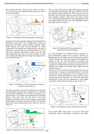
![parameter. Fruits, flowers, flower colors, fragrance, birds’
attraction and water requirement are the main selection
parameter for soft landscaping. In this connection other than
recreational facilities, transpiration corridors are also planned
with soft landscaping. Transportation corridors cover around
34% of DCK land with different row and road categories. The
water requirement for transportation corridors landscaping and
other minor uses will be around 2.3% of total water demand
with highest share at streets. The details are given in map of
Figure 13.
1) Spatial Analysis of Water Demand
According to zonal distribution, DCK comprises of four main
zones; DCK sectors, South Zone, Down Town and Gateway,
as well as miscellaneous area as shown in Figure 14. In zonal
distribution more than half (60%) of water share is required
for residential sectors with a comparatively low water
requirement per unit (0.07g/ft2
). Second largest requirement of
water is in south zone that is almost 15.2 % of the total
demand with a comparatively higher value per unit area
(0.15g/ft2
). The highest water requirement per unit area in City
Gateway and Downtown (i.e. 0.27g/ft2
), that covers around
14% share. Further sectors wise water requirement are given
in Figure 12 and Figure 15 that show the sector wise split of
land use water demand.
2) Temporal Analysis of Water Demand
Many of engineering applications and operational
management of water distribution system are based on the
future water consumption. Therefore, it is necessary to
forecast water demand not only on spatial scale but also with
development time considerations. It is very hard to get a
reliable estimation of future water demand without a clear
understanding of historical and current trends of water use
patterns [29]. Commonly, water demand prediction is divided
into three categories: long - term, medium –term and short-
term periods. Water forecasting in future years used for
distribution system design refers to long-term period. Seasonal
water consumption refers as median-term period, whereas
short –term period concern with daily and hourly water
demand.
Domestic water use by households is a dominant municipal
water requirement in urban areas. Water utilities to make
system plan, design and asset management are important for
municipal water demand, short- and long- term forecasting.
Long term water demand is useful for management and
operation, whereas short term is essential for municipal water
demand short and long term forecasting. Water demand
prediction accuracy achievement is challenging, however ,
because the predicting model must simultaneously consider
multiple factors associated with economic development,
population growth and migration, climate changes, and even
consumer behavioral patterns[30].
The population growth rate of the city is required for
forecasting the domestic water requirements. Future
population prediction is based on the knowledge about the
city, its development of surrounding areas, environments,
potential trade expansion and, infrastructure and
communication network development. As per DCK
development strategy, it is going to develop in three phases;
Short-Term (2012-2015), Mid- Term (2015-2020) and Long-
Term (2020-2030). On the basis of population growth of
Figure 13: Distribution of Water requirement in
Transportation use
Figure 14: Zonal Wise water demand
Figure 15: Sectors wise water demand of DCK
Figure 12: Sector wise split of land use Water
Requirement.
Table 4: Water requirement with respect to DCK development
phases
Development plants Water requirement
after completion
(MG)
Yearly Water
Resource
Development
requirement(MG)
Short-Term (2012-2015) 11.1 3.7
Mid-Term (2015-2020) 20.7 4.14
Long-Term (2020-2030) 11.5 1.15
104
Fourth International Conference on Aerospace Science & Engineering (ICASE 2015) Proceedings](https://image.slidesharecdn.com/conferenceproceedingsicase2015final1-160918062150/85/Conference-proceedings-113-320.jpg)
![DCK, water demand for these three phases has been estimated
as shown in Table 4 and Figure 16 is represented its spatial
distribution.
By considering development plans it is estimated that for
short- term development approximately 11.1 MG water will
be required that will serve the complete demand of the short-
term planned area. However, its water source development
will be tricky in the beginning plan; just for the short term
development plan average annual water resource development
requirement is around 3.7MG per year. However the actual
use of water will be started with the occupancy and use of land
for the respective purpose. It is estimated that in initial stage
only water is required for construction purpose and only 10 to
15 % of water will be required in DCK Camp site till the end
of short term development plan. It is better to develop around
1.5 to 3 MG water resource by the end of short term
development plan.
B. Reduced water demand
A demand reduction measure serves to reduce water demand,
water losses, peak water demand, and non-essential water
uses. Reducing water consumption in the home, market and at
public places is a simple and easy way to decrease water and
energy bills and reduce household’s impact on the
environment. Conserving scarce water resources helps reduce
the need to dam rivers, reduce waste water produced and
treated at sewage plants, lower energy requirements for
treating and transporting water and waste water, and reduce
greenhouse emission.
1) Strategy to Reduction water demand
For the efficient use of water at usage point is more effective
to save water and reduce overall municipal water demand.
There are many methods and strategy for water reduction, but
most feasible and easy to deploy are; Use of Water efficient
plumbing devices or fixtures and Recycling or re-use of grey
water
a) Use of Water efficient plumbing devices or fixtures
In the last two decades the use of water efficient plumbing
fixture has been introduced throughout the world considering
water scarcity. It has been observed that water efficient
appliances in the home can reduce indoor water consumption
by 35-50%[31]. Typically used such devices and reported
water efficiencies are given in the Table 5.
Error! Reference source not found. gives figure for water
demand expected saving in water demand at DCK pertaining
to use of water efficient devices. It is clear from the above
table that the use of the aforementioned devices can save 44 %
water and the average water requirement will be reduced to 30
gpcd. The use of such devices can either be regulated in
building codes for their increased use. It is also suggested that
new home building should be guided to use these devices
through media campaigns. The land use like amenities and
commercial building give more saving by using water
conservation devices.
b) Recycling and re-use of Grey water
For grey water recycling, the overriding principle is safe usage
of recycling water. Therefore, we have not taken grey water
recycling where its safe usage can be questioned or its
consumption is not required. For plot sizes smaller than
500sqyrds, in any land use, have not been considered because
they do not have any green area and grey water usage for
landscaping is suggested only for large size plots. Health
facilities have not been incorporated for calculation of grey
water because of the hazardous nature of medical waste.
Therefore, grey water volume has been computed for
residential plots R5, R10 and R20, commercial plots (C5, C10,
and C20), mixed use (M5, M10, and M20), as well as planned
amenities. For this purpose, grey water shall be treated sites
and reused for landscaping. Amenities especially educational
institutes, produce a lot of grey water. This phenomenon
Figure 16: Water Demand for DCK development phases
Table 5: Water demand using water efficiency devices
Name of efficient device Frequency of
use(per person)
Daily Water use
without water
conservation device
(gal/person)
Daily Water use with
water saving device
(gal/person)
Daily Water saving
with water saving
device
(gal/person)
Annual Water saving
(gal/person)
Low-flush Toilet (1.6gpf) 5.1 flushes /day 204 8.2 12.2 4453
Low- volume showerhead
(2.5gpm)
5.3 minutes/day 15.9 13.3 2.6 949
Low- volume Faucet
(1.5gpm)
4 minutes/day 12 6 6 2190
Front-loading washing
machine (27gpl)
0.37 loads/day 18.9 10 8.9 3249
Water efficient dishwasher
(7gpl)
0.1 loads/day 1.1 0.7 0.4 146
Total 68.3 38.2 30.1 10987
*Assumes conventional toilet at 4gpf, showerheads at 3gpm,faucet at 3gpm, washing machine at 51gpl, and dishwasher at 11gpl[1]
105
Fourth International Conference on Aerospace Science & Engineering (ICASE 2015) Proceedings](https://image.slidesharecdn.com/conferenceproceedingsicase2015final1-160918062150/85/Conference-proceedings-114-320.jpg)

![comparatively high water demand is essential. Karachi water
and sewerage supply is the only water resource for DCK
which already supply insufficient water for Karachi city.
Reuse or recycling of waste water and use of efficient devices
serve as efficient and valuable ways to cope with the scarcity
of water and can reduce the water demand. The estimated
waste water for the DCK is 66% of the total water demand,
taken from the land use; residential, commercial, mixed use
and amenities, can reuse after the treated for landscaping and
agriculture outside the houses. For implementing these
alternate water resources, well-structured planning is
necessary. As for reuse of wastewater, black water drain
system should be separated with grey water and forcefully
implementation of water efficient fixture is essential for the
householder. There will be 45MGD water required for the
whole planning of DCK and water demands by using these
alternate resources are estimated. The results of the first
scenario based on reuse of grey water able of only 7.9 %
reduction of water demand. Whereas in the third scenario,
efficient device use show that efficient fixtures can reduce
water demand up to 39%. The second scenario, based on reuse
of grey water with the use of efficient devices, is considered as
an optimized water demand because of the maximum
reduction in water demand about 43%. After successful
deployment of the suggestion without failure to operate and
maintain the system could result in significant reduction in
water demand. Considering the scarcity of water in the area,
we expect that these critical management practices will be
adopted and implemented.
For further study this research can be extended to estimate the
portable and non-portable water use from the reused waste
water. This research provides a sustainable water resource
management system which is the requirement of the better life
style free from water scarcity which is expected to increase in
future.
VII. ACKNOWLEDGEMENT
The authors are grateful to DHA City Karachi, Pakistan and
Osmani & Company Pvt. Ltd. for sharing planning
information and other relevant literature related to the DCK.
Authors are also thankful to the GIS and planning team of
Osmani & Company Pvt. Ltd. for their great support.
VIII. REFERENCES
[1] OCL, "Interim Report -1 , " Feasibility study for alternate
water supply stretegy including rechagre, reuse and small
dams " Osmani Company (PVT) limited and Pakistan
Defences Officers Housing Authority Karachi 2013.
[2] F. Arbu s, . a. . Garc a- ali as, and . art ne -
Espiñeira, "Estimation of residential water demand: a state-
of-the-art review," The Journal of Socio-Economics, vol.
32, pp. 81-102, 2003.
[3] F. A. Ward, "Decision support for water policy: a review of
economic concepts and tools," Water Policy, vol. 9, p. 1,
2007.
[4] O. Udovyk, "GIS for intergrated water resourses
management," Integrated Urban Water Resources
ManagementNATO Security through Science Series., pp.
35-42, 2006.
[5] R. H. a. H. R. Vassilios A. Tsihrintzis, Fuentes., "Use of
Geographic Information Systems (GIS) in Water
Resources: A Review," Water Resources Management, vol.
10, pp. 251-277, 1996.
[6] Z. X. Xu, K. Ito, G. A. Schultz, and a. J. Y. Li, "Integrated
hydrologica modeling and GIS in water resources
management.," Journal of computing in civil engineering,
vol. 15, pp. 217-223, 2001.
[7] K. K. K. Mark R. Leipnik, and and Hugo A. Loaiciga,
"Implementation of GIS for Water resources planning and
management," Journal of Water Resources Planning and
Management, vol. 119, pp. 184-205, 1993.
[8] A. Gemitzi, V. A. Tsihrintzis, O. Christou, and C. Petalas,
"Use of GIS in siting stabilization pond facilities for
domestic wastewater treatment," J Environ Manage, vol.
82, pp. 155-66, Jan 2007.
[9] K. V. Kalivas DP, Karantounias G, " A GIS for the
assessment of the spatio-temporal changes of
the Kotychi lagoon, western Peloponnese, Greece.," Water Resourece
Management, vol. 17, pp. 19-36, 2003.
[10] G. P. Panagopoulos, G. D. Bathrellos, H. D. Skilodimou,
and F. A. Martsouka, "Mapping Urban Water Demands
Using Multi-Criteria Analysis and GIS," Water Resources
Management, vol. 26, pp. 1347-1363, 2012.
[11] O. Udovyk, "GIS for intergrated water resourses
management," Integrated Urban Water Resources
Management, pp. 35-42, 2006.
[12] X. C. Daene C. Mc Kinney, "Linking GIS and water
resources management models:an object-oriented method,"
Environmental Modelling & Software, vol. 17, pp. 413-
425, 2002.
[13] S. a. S. Ahmad, S. , "Spatial System Dynamics: New
Approach for Simulation of Water Resources Systems,"
Journal of Computing in Civil Engineering, vol. 18, pp.
331–340, 2004.
[14] L. Allen, J. Christian-Smith, and M. Palaniappan,
"Overview of Greywater Reuse: The Potential ofGreywater
Systems to Aid Sustainable WaterManagement," Pacific
Institute 654 13th Street, Preservation Park Oakland,
California.2010.
[15] U. M. Shamsi, "GIS, Remote Sensing, and Master Water
Plan: A Case Study," In Computing in Civil Engineering
and Geographic Information Systems Symposium, pp. 695-
702, 1992.
[16] P. Kirshen, Nvule, D., and Corliss, J, "Estimating urban
and suburban sewerage flows withassistance of GIS
technology," in Proc. ASCE Water Resow Plan. Manage.
Conf, Baltimore, MD, 2-6 August,, 1992, pp. 208-212.
[17] P. R. a. B. S. Giguere, "Application of GIS to waste water
system mmmaster planning in Albuquerque," in ASCE
107
Fourth International Conference on Aerospace Science & Engineering (ICASE 2015) Proceedings](https://image.slidesharecdn.com/conferenceproceedingsicase2015final1-160918062150/85/Conference-proceedings-116-320.jpg)
![National Conference Civil Eng Appl. Remote Sensing GZS,
Washington DC,, 1991, pp. 115-119.
[18] H. P. a. B. outal, D. , "Updating New York city’s sewer
and water main distributionsystems: practical applications
of GIS," in ASCE National Conference Civil Eng Appl.
Remote Sensing GZS, Washington DC,, 1991, pp. 155-164.
[19] OCL, "DHA city Karachi planning report," Osmani
Company (PVT) Limited and Pakistan Defences Officers
Housing Authority Karachi2012.
[20] OCL, "DHA city Karachi ecology Report," Osmani
Company (PVT) Limited and Pakistan Defences Officers
Housing Authority Karachi2012.
[21] U. Nation, "The Millennium Development Goals Report,"
UNITED NATIONS2012.
[22] P. R. Philippe Loubet , Eleonore Loiseau , and V. Bellon-
Maurel, "Life cycle assessments of urban water systems A
comparative analysis of selected peer-reviewed literature,"
Water Reseach, vol. 64, pp. 187-202, 2014.
[23] T. Lu, "Research of domestic water consumption: a field
study in
Harbin, China," Master of Science of Loughborough University,
Water, Engineering and Development Centre Department
of Civil and BuildingEngineering, 2007.
[24] E. M. M. Syed R. Qasim, Guang Zhu, Water Works
Engineering: Planning, Design, and Operation: Prentice-
Hall Of India Pvt. Limited, 2000.
[25] M. Ahmad, "Pakistan Water and Sanitation Operators
Directory," Water and Sanitation program. 2012.
[26] J. P. H. Miguel A. Morales, Kenneth R. Friedman, and
Jacoueline M. Martin., "Estimating commercial,
industrial,and institutional water use on the basis of heated
building area," Journal American Water Works Association
vol. 103, 2011.
[27] R. Tabassum, "Title," unpublished|.
[28] K. H. V. Durga Rao, "Multi-criteria spatial decision
analysis for forecasting urban water requirements: a case
study of Dehradun city, India," Landscape and Urban
Planning, vol. 71, pp. 163-174, 2005.
[29] M. A. Al-Noaimi, "Decelopment of water resources in
Bahrain: A combined approch of supply demand analysis,"
PDh in School of Earth, Ocean, and Environmental
Sciences, University of Plymouth.
[30] C. Qi and N. B. Chang, "System dynamics modeling for
municipal water demand estimation in an urban region
under uncertain economic impacts," J Environ Manage,
vol. 92, pp. 1628-41, Jun 2011.
[31] D. Inman and P. Jeffrey, "A review of residential water
conservation tool performance and influences on
implementation effectiveness," Urban Water Journal, vol.
3, pp. 127-143, 2006.
108
Fourth International Conference on Aerospace Science & Engineering (ICASE 2015) Proceedings](https://image.slidesharecdn.com/conferenceproceedingsicase2015final1-160918062150/85/Conference-proceedings-117-320.jpg)
![Optimized Threshold Calculation based on received
signal characteristics for Blanking Non-linearity at
OFDM Receivers
Ferheen Ayaz
SUPARCO Institute of Technical Training, HR Dte Gen,
Space and Upper Atmosphere Research Commission,
Karachi, Pakistan
ferheen@msn.com
Zehra Ali
Space Electronics Wing,
Space and Upper Atmosphere Research Commission,
Karachi, Pakistan
Zehra.aly82@gmail.com
Abstract—In satellite communications, OFDM (Orthogonal
Frequency Division Multiplexing) is evolving quickly as a well-
established scheme. OFDM based communication system
performance, despite of its robustness and high efficiency, is
greatly affected by the addition of Impulsive Noise (IN). Additive
impulsive noise deteriorates the transmitted signal and overall
performance results poor when signal to noise ratio (SNR) and
symbol error rate (SER) are considered. Blanking nonlinearity
scheme is among the simplest methods to reduce the adverse
effect of impulsive noise at OFDM receivers. The performance of
blanking non-linearity is based upon threshold selection. In
blanking, the received samples whose magnitude exceeds a
certain fixed threshold are considered to be IN-affected and are
therefore set to zero. The value of threshold plays a very
important role in detecting the samples affected by IN. Setting a
fixed threshold does not always determine the IN-affected
samples truly as the OFDM distribution characteristics vary
throughout the signal. Several theoretical methods to optimize
the threshold level to improve system performance have been
reported. This paper reviews some of the threshold optimization
methods and proposes a new method based on some
characteristic distribution of the received signal including
median and peak. This proposed optimized threshold can be used
practically and results in higher or comparable Signal to
Impulsive Noise ratio than the other methods which are
incapable to be adopted in practical OFDM receivers.
Keywords—OFDM; impulsive noise; blanking non-linearity;
threshold; median; peak
I. INTRODUCTION
Orthogonal Frequency Division Multiplexing (OFDM) is a
rapidly growing modulation scheme and is widely adopted in
many wireless applications [1]. Performance of OFDM
modulation scheme for GNSS (Global Navigation Satellite
Systems) is one of the latest research topics [2]. Other
applications of OFDM include 4G mobile satellite systems [3]
and European Digital Terrestrial Video Broadcasting (DVB-T)
[4]. Despite of many advantages of OFDM communication
systems, the performance degradation in them still persists due
to high-power additive Impulsive Noise (IN) pulses and their
random occurrence in a channel [5]. DVB-T systems are
affected significantly by Impulsive Noise [6]. Performance
degradation in OFDM systems due to impulsive noise result in
high Symbol Error Rate (SER) and low Signal to Impulsive
Noise Ratio (SINR) [7].
A number of schemes to eliminate or reduce impulsive
noise from the received signal have been reported. These
schemes aim to increase the Signal to Impulsive Noise Ratio
(SINR) of the overall system. The simple approach to mitigate
impulsive noise from a received signal is to introduce a
memoryless non-linearity at OFDM receiver before
demodulation. Blanking, clipping and hybrid clipping-
blanking schemes have been devised using this approach.
Among all the non-linearity schemes, blanking is the easiest to
implement as it only converts the high amplitude samples
corrupted by IN to zero [7-8]. The blanking non-linearity
scheme revolves around the decision of whether the received
sample is affected by impulsive noise or not and then
changing it to zero. The decision is taken by a fixed parameter
known as threshold level or simply threshold. The threshold
level indicates if IN has corrupted the received signal sample
or the original sample value is retained at the receiver exactly
as transmitted. If the received sample’s amplitude exceeds the
threshold level, it is considered to be corrupted by IN and
therefore it is multiplied by zero. If the threshold level is
higher than the sample’s amplitude, it is assumed to be the
original sample value unaffected by IN and hence multiplied
by one to provide no change to the sample [9].
Fixing a value of threshold is very important as it defines
the overall SINR of the system. A low value of threshold may
blank the original signal samples which were initially not
corrupted by IN and a high threshold value may pass the IN
affected samples without blanking [10]. Fig. 1 illustrates the
two values of threshold to be used with blanking nonlinearity
on a signal affected by impulsive noise.
Since the performance of blanking non-linearity is greatly
affected by the selection of threshold, the choice of an
optimized threshold is a crucial decision. Optimized threshold
has been calculated in literature by different methods [11-12].
However, theoretical calculations of optimized threshold
109
Fourth International Conference on Aerospace Science & Engineering (ICASE 2015) Proceedings](https://image.slidesharecdn.com/conferenceproceedingsicase2015final1-160918062150/85/Conference-proceedings-118-320.jpg)
![cannot be used at practical OFDM receivers where probability
of IN occurrence is unknown. In this article, we review the
two threshold optimization techniques for blanking
nonlinearity; first is adaptive threshold optimization method
which maximizes the Signal to Impulsive Noise Ratio (SINR)
[11] and second is dynamic peak based threshold estimation
method [12]. We also propose a new method for calculating
threshold based upon median and peak of the received signal.
The proposed technique of threshold calculation has the
advantage over the other two schemes as it can be used at
practical OFDM receivers without the information of original
signal transmitted, probability of impulsive noise occurrence
and maximum SINR achievable.
0 2 4 6 8 10 12
x10
4
0
2
4
6
8
10
12
OFDM symbols corrupted by IN
Amplitude
OFDM symbols
Impulsive Noise
Threshold 1
(Too low)
Threshold 2
(Too high)
Fig. 1. Two threshold levels considered for blanking IN-affected samples.
The organization of the remaining paper is as follows:
OFDM transmission system with blanking non-linearity
scheme is described in Section II. Section III overviews the
two threshold optimization techniques and proposes Median
Based Threshold (MBT). Section IV includes simulation
results in which MBT is compared with the other threshold
optimizing techniques with respect to Signal to Impulsive
Noise Ratio (SINR) and Symbol Error Rate (SER).
Conclusion is presented in Section V.
II. THE OFDM TRANSMISSION SYSTEM
OFDM transmission is represented in the form of block
diagram as shown in Fig. 2.
Fig. 2. OFDM transmission system with blanking scheme at receiver.
In OFDM transmission, the time-domain form of
transmitted signal s(t) is found by applying inverse Fourier
transform to the frequency-domain signal by using
11 2 . .
( ) exp , 0 t T
S0
N k t
s t S j
k TN k S
(1)
Where S
k denotes frequency-domain signal, N is number
of subcarriers, 1j , and sT is active symbol interval.
Impulsive Noise (IN) is represented as ki and is included to the
transmitted signal using Bernoulli-Gaussian random process
as follows:
, 0 k N-1k k ki b g (2)
Where ‘ 1kb ’ or ‘ 0kb ’ according to Bernoulli process
of sequence. The probability for ‘ 1kb ’ is p and ‘ 0kb ’
1 p . Whereas, kg is additive white Gaussian noise (AWGN)
with variance
22
(1/ 2) [ ].i kE g Hence, the signal-to-IN
ratio (SIR) can be given by; 2
1010log (1/ )iSIR . It is
worthwhile mentioning here that in this paper we represent
theoretical signal to impulsive noise ratio as SIR and practical
signal to impulsive noise ratio as SINR. The time-domain
signal ( kr ) received after addition of IN and AWGN can be
represented as
if 0
,
if 1
k k
k
k k k
s b
r
s i b
(3)
The received signal is passed to the blanking non-linearity
block. The output of blanking non-linearity ky is then fed to
the OFDM demodulator for the further processing and is
represented as
, 0 k N-1k k ky r d (4)
Where kd represents the blanking non-linearity scheme and
is given as
1
0
k
k
k
r T
d
r T
(5)
Where T is the blanking threshold level and
0, 1, ..., 1k N . Optimizing the value of T for increasing
effectiveness of blanking non-linearity is described in the next
section.
III. THRESHOLD OPTIMIZATION
A. Overview of Threshold Optimization Techniques
An optimized threshold is very important for efficient
blanking of Impulsive Noise. Two threshold optimizing
methods are discussed in this section.
110
Fourth International Conference on Aerospace Science & Engineering (ICASE 2015) Proceedings](https://image.slidesharecdn.com/conferenceproceedingsicase2015final1-160918062150/85/Conference-proceedings-119-320.jpg)
![An Adaptive Threshold (AT) method is reported in [11]. AT
is the threshold which gives maximum signal to impulsive
noise ratio (SINR) according to (6).
max( ( ))AT SINR T (6)
AT for an OFDM signal is found by applying Blanking
nonlinearity to IN affected received symbols at all thresholds
varying from 0 to 15 with an increment of 0.1 and calculating
SINR each time. The threshold which gives maximum SINR
is denoted by AT as shown in Fig. 3.
0 5 10 15
0
5
10
15
20
Threshold
SINR
AT at max(SINR)
Fig. 3. SINR after applying blanking nonlinearity with respect to threshold
and AT, SIR=-15 dB, p=0.01.
Another optimized threshold is known as Dynamic Peak
Based Threshold (DPBT) [12]. In DPBT estimation method
the peak of the OFDM signal is calculated before it is
transmitted through a noisy channel. At OFDM receiver,
blanking nonlinearity scheme is used with threshold equal to
the peak of the original signal as shown in equation (7).
max( ( )), 0 k N-1kDPBT s dB (7)
Where DPBT denotes the threshold in Dynamic Peak
based Threshold Estimation Method.
Both of the optimized thresholds; AT and DPBT cannot be
used practically as it is impossible to find the exact peak of
transmitted signal and maximum SINR at OFDM receiver
[12].
B. The Proposed Median Based Threshold (MBT)
Calculation Method
Due to practical shortcomings of the techniques discussed
above, a new technique is therefore devised to calculate an
optimized threshold, known as MBT, by using the distribution
characteristics of the received signal which are its peak and
median. Fig. 4 illustrates the method to calculate MBT.
Figure 4. Method to calculate Median Based Threshold.
MBT is given as:
max( ) ( )
,0 k N-1k kr median r
MBT
(8)
Where kr is received signal, max(rk) denotes the peak of the
received signal and is a threshold slope to be fixed at the
receiver. is set to achieve high SINR. Its optimum value
lies in the range for 4 to 6. In our simulations, it is kept 4
which was found to be optimized by using hit and trial
method. Setting an optimal value of is a better approach as
compared to selecting a fixed optimal threshold because a
threshold value may lie from 1 to 15 but the range of β is
comparatively lesser and does not vary with different
probabilities of IN occurrence, unlike a fixed threshold.
Performance comparison of the three methods is shown in
the next section.
IV. SIMULATION RESULTS
The OFDM system is simulated using MATLAB with 16-
QAM modulation, SIR=-15dB, number of subcarriers, N =
10^5, and
22
(1/ 2) [ ]i kE g . Probability (p) of presence of
IN is taken as p=0.01, which suggests that 1% of the received
samples are corrupted by Impulsive Noise. The output SINR is
obtained by
2
2
[ ]
[ ]
k
k k
E s
SINR
E y s
(9)
Fig. 5 shows the SINR achieved by three optimized
111
Fourth International Conference on Aerospace Science & Engineering (ICASE 2015) Proceedings](https://image.slidesharecdn.com/conferenceproceedingsicase2015final1-160918062150/85/Conference-proceedings-120-320.jpg)
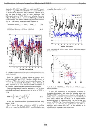
![5.5 6 6.5 7 7.5 8 8.5 9
10
-0.4
10
-0.3
SINR(dB)
SER
AT
DPBT
MBT
Fig. 8. SER with respect to SINR after applying blanking nonlinearity using
AT, DPBT and MBT, p=0.01.
16 16.5 17 17.5 18 18.5
10
-4
10
-3
10
-2
SINR (dB)
SER
AT
DPBT
MBT
Fig. 9. SER with respect to SINR after applying blanking nonlinearity using
AT, DPBT and MBT, p=0.03.
V. CONCLUSION
Two methods of optimizing thresholds of blanking
nonlinearity at OFDM receivers are reviewed. Both of the
methods are purely theoretical and infeasible to use in
practical OFDM receivers. One of the methods suggested peak
of transmitted OFDM signal as the optimized threshold but it
only worked for a single probability of impulsive noise
occurrence and did not give high SINR at other probabilities.
A new method of calculating optimized threshold based on
peak and median of the received signal samples is proposed
which can be used practically. This method results in higher
SINR and lower SER than the method which calculates
threshold by determining the original signal peak for different
probabilities of Impulsive Noise occurrence. The proposed
method is sometimes incapable of achieving the maximum
SINR as that achieved by adaptive threshold optimization
method. However, the SINR achieved by this method is
always close to the maximum and acceptable in practical
scenarios.
Acknowledgment
We gratefully acknowledge Training Division, HR Dte
Gen, Pakistan Space and Upper Atmosphere Research
Commission for their kind coordination in publishing the
article.
References
[1] S. H. Han, and J. H. Lee, “An overview of peak-to-average power ratio
reduction techniques for multicarrier transmission,” IEEE Personal
Communications, vol. 12, no. 2, April 2005, pp. 56–65.
[2] X. Liu, M. Liang, Y. Morton, P. Closas, T. Zhang, and Z. Hong,
“Performance evaluation of MSK and OFDM modulations for future
GNSS signals,” GPS Solutions, vol. 18, no. 2, January 2014, pp. 163-
175.
[3] A. Vaneli-Corali, G. E. Corazza, G. K. Karagiannidist, P. T.
Mathiopoulosl, D. S. Michalopoulost, C. Mosquera, S. Papaharalabost,
and S. Sca1ise, “Satellite Communications: Research Trends and Open
Issues,” International Workshop on Satellite and Sapce Communication
(IWSSC’07), IEEE, 2007, pp. 71-75.
[4] S.V. Zhidkov, “Impulsive noise suppression in OFDM-based
communication systems,” Consumer Electronics, IEEE Transactions,
2003, vol. 49, no. 4, pp. 944-948.
[5] M. Katayama, T. Yamazato, & H. Okada, “A mathematical model of
noise in narrowband power line communication systems,” IEEE Journal
on Selected Areas in Communications, vol. 24, no. 7, 2006, pp. 1267-
1276.
[6] Y. Wu, “Performance comparison of ATSC 8-VSB and DVB-T
COFDM transmission systems for digital television terrestrial
broadcasting,” IEEE Transactions on Consumer Electronics, ,vol. 45, no.
3, 1999, pp. 916-924.
[7] S.V. Zhidkov, “Analysis and comparison of several simple impulsive
noise mitigation schemes for OFDM receivers,” IEEE Transactions on
Communications, vol. 56, no. 1, 2008, pp. 5-9.
[8] U. Epple, K. Shibli, and M. Schnell, “Investigation of blanking
nonlinearity in OFDM systems,” Iternational Conference on
Communications (ICC), June 2011, pp. 1-5.
[9] S.V. Zhidkov, “Performance analysis and optimization of OFDM
receiver with blanking nonlinearity in impulsive noise environment,”
IEEE Transactions on Vehicular Technology, ,vol. 55, no. 1, 2006, pp.
234-242.
[10] S.V. Zhidkov, “On the analysis of OFDM receiver with blanking
nonlinearity in impulsive noise channels,” Proceedings of International
Symposium on Intelligent Signal Processing and Communication
Systems (ISPACS 2004), November 2004, pp. 492-496.
[11] U. Epple & M. Schnell, “Adaptive threshold optimization for a blanking
nonlinearity in OFDM receivers,” Global Communications Conference
(GLOBECOM 2012), IEEE, December 2012, pp. 3661-3666.
[12] E. Alsusa & K. M. Rabie, “Dynamic peak-based threshold estimation
method for mitigating impulsive noise in power-line communication
systems,” IEEE Trans. on Power line, vol. 28, no. 4, October 2013, pp.
2201-2208.
This article is sponsored by Pakistan Space and Upper Atmosphere Research Commission
113
Fourth International Conference on Aerospace Science & Engineering (ICASE 2015) Proceedings](https://image.slidesharecdn.com/conferenceproceedingsicase2015final1-160918062150/85/Conference-proceedings-122-320.jpg)

![ AMTS overawed all the problems that occur from
IMTS and works on 900 MHz
In Norwegh, OLT which worked on 160 MHz VHF
band was the first land mobile telephone network. In
regularity inflection it worked on 160 -162 MHz for
the mobile portion and in base station it is 168-
170MHz.
MTD include high speed internet structure with fixed
wireless facility that deals constantly on internet
access.
III. FIRST GENERATION (1G)
The 1st
genera of mobile interaction was presented in the
1980 and analog transmission was used as communication.
The 1st
mobile system (1979) developed by Nippon Telephone
and Telegraph (NTT) in Tokyo, Japan. Mobile Telephones
(NMT) and Total Access Communication Systems (TACS)
were two most popular system of analogue system [17].
Frequency division multiple access (FDMA) with channel
capacity of 30 KHz and frequency band 824-894 MHz use
incidence variation system for radio communication based is
derived from a technology called Advance Mobile Phone
Service (AMPS) [14, 15].
Fig 1. 1G Mobile Phone [6]
The initial step of mobile communication is NTM. It
is in the result of heavy and increased usage of physical
cellular communication. The variations of NMT are NMT-450
and NMT-900. The figures specifies usage of band rate
correspondingly. NMT-900 contain other Channels as
compared to NMT-450. NMT cells cast-off full duplex
program. Permitting in real-time acceptance and vocal sound
communication [14].
AMPS was a reporter cellular telephone framework typical
creates in 1983 by Bell Labs, America. It was an initial genera
mobile phone program which use isolated frequencies in place
of individually discussion. It was changed commencing more
seasoned arrangements by "back-end" setup of calls usefulness
that permitted bigger telephones quantities to be bolstered
concluded geological region. In 1983, an aggregate of 40MHz
of range in the 800 MHz band was assigned by FCC for
AMPS. In 1989, additional 10 MHz has been charged to
AMPS because of ascent of cell framework limit. Uplink
frequency for AMPS remains 824- 849MHz and downlink
frequency stays at 869-894MHz. Independently AMPS
frequency is 30 KHz wide [16].
Fig 2. Architecture of Advance Mobile Phone Services (AMPS) [6]
IV. SECOND GENERATION (2G)
After first genera similarity mobile statement system 2G
mobile system was announced around 1991.concept of 2G
based on many base stations where each station circulated
consistently over the world to communicating with the users.
To converse more and more users various access procedures
are used i.e. FDMA, TDMA, and CDMA [10]. 2G technology
make procedures of compression decompression procedure
(codec) and family members of this generation are 2G (GSM,
GPRS, EDGE).
Digital signal usage among recipients and tower build the
framework ability in two forms
1) Digital sound data be able to smashed and multiplexed
proficiently in this way consenting more data is delivered into
the equal quantity of radio data transmission.
2) Less radio power is released while using digital
systems. Therefore creation of small size of and altering better
mobiles in similar quantity of space. Two standard was used
for 2nd
genera technology – CDMA and TDMA on center of
multiplexing. In drill, TDMA and CDMA systems share with
FDMA. TDMA expression is utilized to assign frameworks,
which partition the channel into frequency openings, later on
isolate every rate space into various time openings. Also,
CDMA is truly a cross breed of CDMA and FDMA where the
station is initially partitioned into recurrence openings.
115
Fourth International Conference on Aerospace Science & Engineering (ICASE 2015) Proceedings](https://image.slidesharecdn.com/conferenceproceedingsicase2015final1-160918062150/85/Conference-proceedings-124-320.jpg)
![Fig 3. 2G Mobile Phone [6]
GPRS is a cell phone wireless technology established
amongst prototype, 2G, and predecessor, 3G) [12]. It’s a radio
innovation for GSM systems that upgrades bundle changing
over conventions, set up period for ISP systems, choice to pay
according to the sent data, instead of association period. In
packet transferring method, material to be delivered is
damaged into packets, size of the packets is in kb, after that
these are moved through network among various ends, each
data packet contain address of destination. Data transmission
and network connection is the provision of GPRS.
EDGE is an ordinal cell phone technique that actions as a
bolt-on enrichment to General Packet Radio Service (GPRS)
networks. It is ideal as compared to GSM because it carries
packet switch data and circuit switch data [11]. Black berry
N97 and N95 mobile phones are famous because of EDGE
technology. By using EDGE technology, no additional
hardware and software resources are required for making
EDGE technology work. Any of the extra expense are not
required for developing such technology [13].
Fig 4. GPRS Architecture [6]
V. THIRD GENERATION (3G)
3G is the innovative generations for cellular interaction
facilities, its services area centered on procedural values of
IMT-2000 containing the consistency, accuracy and also speed
(rate in which data is transferred) that is minimum 200kb per
second [11]. Outside of cell phone, more data transfer ratio
permitted 3G links in personal computers, digital gaming
equipment, tablets, and smart phones including all devices that
are able to take benefit by using high and fast quality of
internet usage. Working capacity of devices and functionality
of devices can be increased many times with the usage of fast
and reliable internet connection. Better safety and less threat is
offered while connecting and transferring data to other
wireless devices by using 3G [2, 3]. Three basic technologies
are covered by 3G that is CDMA2000, TD-SCDMA - Time-
division Synchronous Code-division Multiple Access and W-
CDMA (UMTS) Wideband Code Division Multiple Access.
The vital role of 3G knowhow is, it offers high transfer of data
transmission and improved speed. Packet-switching technique
is used in 3G that is considered more realistic and also much
faster as compared to the previous used technologies and
techniques, issue with it is it requires a totally different
groundwork as compared to the 2G systems.
Fig 5. CDMA Architecture [6]
Mobile communication market is increasing on a
very fast pace, usage of mobile phone industry is increasing in
leaps and bounds. Almost one billion customers globally are
benefiting from cellular phone industry, in which two-thirds
are GSM customers. One of the firmest growing wireless
technology is known as CDMA, it is developing its
subscribers base signify cantle around the world. Nowadays
CDMA subscribers are crossing the line of 200 million users.
3G networks enable network workers to deal customers an
extensive variety of latest progressive facilities and also
realizing better and superior connection ability through
healthier spectral efficiency.
Fig 6. 3G Mobile Phone [6]
116
Fourth International Conference on Aerospace Science & Engineering (ICASE 2015) Proceedings](https://image.slidesharecdn.com/conferenceproceedingsicase2015final1-160918062150/85/Conference-proceedings-125-320.jpg)
![VI. FOURTH GENERATION (4G)
4G technology uses 3G as a inheritor, developed for the
broadband capabilities with the services of 3G to enable the
high data rate streaming i.e.20 Mb/s per customer, Quality of
services, Fast Speed, Faster Response Time, Routing
efficiency, Higher Bandwidth and Lower Power consumption.
Speed for low mobility is 1 gigabit per second (Gbit/s) and
100 megabits per second (Mbit/s) for peak speed. NTT Do Co
Mo was first successor to achieve. Downloading of packet
transmission at a moving speed of almost 20km/h is 1Gbps in
Tokyo, Japan on June 23rd, 2005 [2]. 4G technology is
combination of IP-Based voice, Seamless access,
Personalization, Quality of services. Its main purpose is to
access network anytime, anywhere and anyhow. 4G wireless
communication technology is furthermore discussed as
“MAGIC”. MAGIC word stands for mobile multimedia, any-
where, global mobility solutions over, integrated wireless,
customized services.
Need for this platform is to integrate pervious mobile
technologies entirely which are present that is GSM, GPRS,
IMT-2000, Wi-Fi, Bluetooth,
WCDMA, HSDPA, CDMA2000 and EVDO, provide
correspondence to user expectations for various services.
Mobile WiMAX regularities and Long Term Evolution (LTE)
rules were deployed for 4G but failed to satisfy the IMT-
Advanced requirement, may well though measured as 4G.
Later on LTE Advanced (latest release of LTE) standardized
by the 3GPP (Third Generation Partnership Project) and
802.16m uniformed by IEEE (that is WiMAX). Demand of
IMT-Advanced for the generations of interactive mobile
services by providing a global platform is increased to gain
unified messaging, quicker information admittance, improved
roaming competencies and broadband multimedia [16].
A. LTE Advanced
LTE is not such a new technology but some essential
enhancements in LTE to improve existing LTE network. It
was officially candidate of ITU-T (International
Telecommunication Union- Telecommunication), meeting the
requirements of the IMT-Advances standard and also
standardized by 3GPP. LTE Advanced has 30bps/Hz peak
spectrum downlink value and 15 Bps/Hz peak spectrum uplink
value, can be enhanced if multiple-input multiple-
output (MIMO) (that is antenna arrays) remain used. Both
coordinated multipoint (COMP) and MIMO remained
recognized such as the crucial procedures for LTE [2].
Fig 7. LTE Advance Architecture [17]
VII. FIFTH GENERATION (5G)
5G (Mobile and wireless Network) can make the perfect
wireless real world without any limitation is known as World
Wide Wireless Web (WWWW).
Beyond the 4G/IMT-Advanced standards 5G symbolizes the
next utmost chief level of cellular phone technology genera.
5G is still not considered and used as an official term on
behalf of any specific requirement and design and also not
publically used by telecommunication companies or
standardization such ITU-R (International Telecommunication
Union-Recommendation), 3GPP, WiMaxForum (Worldwide
Interoperability for Microwave Access) [2]. Every new release
of technology enhances the system performance with some
advance capabilities. 5G technology must be something else
than previous technologies, whose purpose is not only to
increase the throughput but also consider the other
requirements.
Improved coverage of geographical zone and high
rate for data transfer at the edge of the mobile phone
Truncated power and battery consumption
Accessibility of numerous data transmission tracks
Nearby 1 Gbps data rate is definitely thinkable
Additional Security
Energy effectiveness and spectral efficiency are good
[17]
117
Fourth International Conference on Aerospace Science & Engineering (ICASE 2015) Proceedings](https://image.slidesharecdn.com/conferenceproceedingsicase2015final1-160918062150/85/Conference-proceedings-126-320.jpg)
![Fig 8. 5G Mobile Phone [17]
5G mobile technology will be powerful and
demanding in future due to including most powerful features.
Also it will change the concept of using mobile phones with
more bandwidth. Customers certainly not have experience of
such great and fast tracking technology. The architecture of
the fifth generation consists of cellular networks
interoperability (contains of a customer station and number of
autonomous radio access technologies (RAT)) and wireless IP
based model [5]. User terminal has a significant role in this 5G
technology system. Proposed 5G architecture is shown in fig
8. 5G technology deal with camera, large phone memory,
MP3 recording, dialing speed, video player, audio player and
many creative, innovative and imaginative technologies [13].
Fig 9. Functional Architecture for 5G- Network [18]
VIII. SIXTH GENERATION (6G)
The 6G technology will combine the 5G satellite network
and mobile wireless system. Satellite network include
telecommunication satellite, navigational satellite, imaging
satellite, environmental information system. These system
used for data, voice, video broadcasting and internet; weather;
environmental information Collection; and global positional
system (GPS) respectively [2]. At the same time Fifth
generation will focus on user terminals but it is necessary for
terminals to have access of different wireless technologies.
Roaming and handoff will be the big issue of 6G because of
the different network stations. Solving the problem of handoff
and roaming is still a question. But the charges of mobile call
will be relatively high [8].
IX. UPCOMING GENERATIONS
Upcoming technologies will provide the real image of
wireless world with less boundaries. Artificial intelligence and
ubiquitous network will provide universal computing from
anywhere, anytime, and any device. User can instantly linked
to several technologies and perfectly move between them.
X. COMPARISON
We compare all the technologies of Mobile Technology in
term of data bandwidth, standards, technology, multiplexing,
switching see table 1. [6]
XI. CONCLUSION
Wireless communication technologies has captured the
market since its first start. This study provides the better
understanding of the previous and present technologies along
with their performances, portals, advantage and disadvantages
of one generation to other and also predict incoming future
technologies.
.
REFERENCES
[1] F. R. Y. Chengchao Liang, "Wireless Virtulization for Next Generation
Mobile Cellular Networks," in IEEE Wireless Communications,
February 2015.
[2] P. Sharma, "Evolution of Mobile Wireless Communication Networks-
1G to 5G as well as Future Prospective of Next Generation
Communication Network," in International Journal of Computer
Science and Mobile Computing, August 2013.
[3] E. M. I. A. E. U. M. A. Engr. Muhammad Farooq, "Future Generations
of Mobile Communication Networks," in Academy of Contemporary
Research Journal, January 2013.
[4] A. G. Roopali Sood, "Digital Society from 1G to 5G: A Comparative
Study," in International Journal of Application or Innovation in
Engineering & Management (IJAIEM), February 2014.
[5] R. Rajan, R. Baweja and R. Kumar, "Review on Different Multiple
Access Technique Used in Wireless Communication," in International
Journal of Research (IJR), November 2014.
[6] P. S.Venkata Krishna Kumar, "A Study of Wireless Mobile
Technology," in International Journal of Advanced Research in
Computer Science and Software Engineering, January 2014.
[7] V. G. APANA BHAT, "EVOLUTION OF 4G: A STUDY,"
International Journal of Innovative Research in Computer Science &
Engineering (IJIRCSE), February 2015.
[8] A. S. J. R. Sarmistha Mondal, "A Survey on Evolution of Wireless
Generations 0G to 7G," International Journal of Advance Research in
Science and Engineering- IJARSE,.
[9] A. A. J. I. Nabeel ur Rehman, "3G Mobile Communication Networks,"
EXPLORE SUMMER 2006, 2006.
[10] N. Schmitz, "The Path To 4G Will Take Many Turns," 1 March 2005.
[Online]. Available: http://electronicdesign.com/4g/path-4g-will-take-
many-turns.
[11] A. G. R. S. O. Z. Xichun Li, "The Future of Mobile Wireless
Communication Networks," 2009 International Conference on
Communication Software and Networks, 2009.
[12] A. R. Mishra, Fundamentals of Cellular Network Planning and
Optimisation: 2G/2.5G/3G... Evolution to 4G, John Wiley & Sons
©2004, 2004.
[13] A. F. Molisch, Wireless Communications, Wiley, 2010.
[14] F. ADACHI, "Wireless Past and Future--Evolving Mobile
Communications Systems," IEICE TRANSACTIONS on Fundamentals
of Electronics, Communications and Computer Sciences, 2001.
118
Fourth International Conference on Aerospace Science & Engineering (ICASE 2015) Proceedings](https://image.slidesharecdn.com/conferenceproceedingsicase2015final1-160918062150/85/Conference-proceedings-127-320.jpg)
![[15] D. Y. L. D. J. S. D. Amit Kumar, "Evolution of Mobile Wireless
Communication Networks: 1G to 4G," International Journal of
Electronics & Communication Technology, December 2010.
[16] A. Pashtan, "wireless terrestrial communication: cellular telephony,"
TELECOMMUNICATION SYSTEM AND TECHNOLOGIES, 2006.
[17] G. M. K. A. Arun Agarwal, "The 5th Generation Mobile Wireless
Networks- Key Concepts, Network Architecture and Challenges,"
American Journal of Electrical and Electronic Engineering,, vol. 3, no.
2, pp. 22-28, February 2015.
[18] [Online].Available:http://www.prismatelecomtesting.com/products/prod
ucts-overview/radio-interface-simulation/uesim/.
TABLE 1. COMPARISON OF MOBILE TECHNOLOGIES
Generation Features 1G 2G 3G 4G 5G
Years 1980s 1990s 2000s 2010s 2020s
Data Bandwidth 2kbps 64kbps 2Mbps 200Mbps 1Gbps
Standards AMPS TDMA, CDMA,GSM,
GPRS
WCDMA Single unified
standards
Single unified standards
Technology Analog cellular Digital Cellular Broadband with
CDMA, IP
Technology
Unified IP & Seamless
combination of
broadband,
LAN,WAN & WLAN
Unified IP & Seamless
combination of
broadband, LAN,WAN
& WLAN,WWWW
Service Mobile technology
(voice)
Digital Voice, SMS,
Higher Capacity
Packetized
Integrated high
quality audio, video
& data
Dynamic information
access, wearable
Devices
Dynamic information
access, wearable
Devices with AI
capabilities
Multiplexing FDMA TDMA,CDMA CDMA CDMA CDMA
Switching Circuit Circuit & Packet Packet All Packet All Packet
119
Fourth International Conference on Aerospace Science & Engineering (ICASE 2015) Proceedings](https://image.slidesharecdn.com/conferenceproceedingsicase2015final1-160918062150/85/Conference-proceedings-128-320.jpg)
![Intelligent Detection of Distributed Flooding Attack
in Wireless Mesh Network
M.Altaf Khan
Institute of Information Technology
Kohat University of Science & Technology
Kohat, Pakistan
altaf_apc@yahoo.com
Shafi Ullah Khan
Institute of Information Technology
Kohat University of Science & Technology
Kohat, Pakistan
skkust@hotmail.co.uk
Amjad Mehmood
Institute of Information Technology
Kohat University of Science & Technology
Kohat, Pakistan
amjadiitkust@gmail.com
Zeeshan Iqbal
Institute of Information Technology
Kohat University of Science & Technology
Kohat, Pakistan
Zeeshan.zn@gmail.com
Abstract—Multi-hop wireless mesh network (WMN) is a
growing and promising technology that fulfills the requirements
of next generation wireless networking by providing an extensive
assortment of applications that were not assumed to be supported
by a wireless network. In WMN, a Gateway is the only way of
integrating it with other wireless and wired networks. Due to this
critical role, gateways in WMNs are targeted by diverse security
threats. A distributed denial of service (DDoS) attack is one of
the prime security threats to WMN. DDOS attack is an explicit
attempt to prevent the legitimate users from accessing their
service. In a distributed flooding attack, gateway can be easily
exploited by the attackers with the aim to reduce the available
network bandwidth for the valid users. Hence network
performance is reduced and also destruct the services provided to
the end users. Numbers of detection mechanisms have been
provided by researchers in this regard. However, due to
advancements in the attacking tools and techniques, more
intelligent efforts are required in terms of precision and
competence, to protect the WMNs from such attacks. In this
paper, an intelligent mechanism called Distributed Flooding
Attack Detector (DFAD) is proposed with the aim to detect
distributed flooding attacks in WMNs. Network simulator (NS2)
is being used to evaluate the performance of DFAD.
Keywords—Wireless Mesh Network, Distributed Denial of
Service Attack, Mobile Ad-hoc Network, Artificial Neural
Network, Back-Propagation
I. INTRODUCTION
A multi-hop and multi-radio wireless mesh network
(WMN) is a decentralized, dynamically self-organized and
self-configured network. Connections among the nodes in
WMN establish without any central controlling body using
partial or complete mesh topology [1]. Two types of nodes are
existed in a typical WMN i.e. mesh node (MN) and mesh
router (MR). MN may either be static or mobile having one
wireless interface. MRs forms a multi-hop backbone of the
WMN by providing self-configured and self-healed links.
Sometimes, in WMN, a MR may have both wired and wireless
interfaces which enables it to provide functionality of gateway.
Unlike conventional routers, MR exhibits some additional
routing functions to bear mesh networking. Moreover, due to
multi-hop support, mesh routers provide more coverage with
low transmission power than conventional routers. WMNs can
be classified into three main architectures i.e. infrastructure-
based, infrastructure-less and hybrid WMN [2]. Infrastructure-
based WMN is composed of both MNs and MRs.
Infrastructure-less WMN seems to be a pure mobile ad-hoc
network (MANET), because it is consisted of only MNs that
may also carry out routing and self-configuration to form a
peer to peer wireless network. Hybrid WMN is composed of
MNs and MR, where MRs are used to form backbone of WMN
and MNs offer routing abilities in order to achieve an enhanced
coverage and connectivity in the interior WMN. In both
infrastructure-based and hybrid WMNs, through mesh gateway
(MG), a node in WMN can communicates with other existing
networks. Hence, MG plays a vital rule for instigation or
termination of traffic in WMN. So it is mostly targeted by
intruders during different attacks. Once MG is being
compromised, all the provided services of WMN are affected
and hence degrades its performance.
WMNs have made life of its users easier. However, some
serious security threats may be faced by the WMN that may
compromise the confidentiality, integrity or availability of a
WMN [3]. Confidentiality is being compromised through
several attacks like eavesdropping, traffic analysis, corrupt
access point, war driving attack, and brute force attack. Black-
hole, worm-hole, grey-hole etc. are the attacks through which
integrity of WMNs are being compromised. Availability is
compromised by many DOS attacks including TCP SYN-
flooding attack, UDP-flooding attack and smarf attack, where
intruders try to prevent normal services or to make the
network resources unavailable for the legitimate users. When
a DOS attack is implemented by thousands of attackers
simultaneously, with the aim to increase the severity of attack,
it is identified as DDOS attack. An intruder launches such
attack by sending a massive bulk of ineffectual packets
concurrently towards victim, through huge number of
compromised nodes also known as zombies [4]. These
zombies may either be internal or external to the victim’s
network. Distributed flooding attack (DFA) is a one of the
classical approach to launch DDOS attack in WMNs using
120
Fourth International Conference on Aerospace Science & Engineering (ICASE 2015) Proceedings](https://image.slidesharecdn.com/conferenceproceedingsicase2015final1-160918062150/85/Conference-proceedings-129-320.jpg)
![tools like Trinoo, Tribe Flood Network (TFN), Shaft, Knight
and Trinity [5].
Anomaly based DDoS attack is being detected in [6].
Features of malicious packets are analyzed using radial base
function neural network (RBFNN). A vector of seven features
is being used for activation of RBFNN and classification of
incoming packets flows into classes of attack traffic or normal
flows. Proposed method is evaluated through datasets of
UCLAD. Proposed method classified the incoming traffic into
class of normal or attack traffic, but it cannot classify and
identify the type of attack. A statistical approach, based on
values of numerous features is implemented in [7] to detect
attack traffic. Proposed method used a module for features
extraction and then extracted features are stored in a database
for identification and classification of normal and malicious
packets flows. A novel approach is presented in [8] to detect
flooding and IP spoofing attack. Prevention of flooding attack
is accomplished through considering clock values of
individual node of network. A combined data mining
approach is used in [9] against DDoS attack for detection of
protocol anomaly. In the proposed method for extraction of
features network traffic is utilized and then a classification
algorithm based on data mining is used to cluster incoming
traffic into normal and attack flows.
For detection of such attack numerous techniques are
proposed so far, but the techniques that are based on
intelligent schemes are proved to be more proficient
alternatives in this regard [10,11,12] . Still there is a need to
propose more mechanisms to handle this attack. Our proposed
mechanism is more intelligent and reliable then the
mechanism proposed earlier for detection of DFA in WMNs.
II. PROPOSED MECHANISM
Due to self-configuration and dynamic changes in
topology of WMN, ANN is considered to be the most suitable
technique amongst all other intelligent techniques to detect
distributed flooding attack [5]. Our proposed mechanism i.e.
distributed flooding attack detector (DFAD) is based on ANN
technique and is adaptive in nature.
ANN used the concepts of biological neural networks
found in human brain. With the assistance of this network a
brain involves millions of interconnected neurons to fully
control the human body. Fig.1 depicts the basic structure of a
biological neuron. It illustrates some important components of
a neuron. Actual cell body of the neuron is constructed by
Soma. It is composed of a nucleus and plasma. Information
regarding to innate traits is provided by the nucleolus and
plasma generates material required by neurons. Dendrites and
Axons are used during communication with other neurons.
Through synaptic terminal an Axon spreads out received
signal to other neurons [13].
Following the same concepts, ANN is a network of
interconnected nodes (neurons) that provide required solution
after performing parallel processing. Structure of earliest ANN
called perceptron, is given in the Fig.2.
Using equations (1,2,3), If Sum of the product of binary
inputs (Z1, Z2…. Zn) and their associated weights (W1,
W2…....Wn) is found greater or equivalent to “0” then “f” i.e.
an activation function will turn out “1” as output if not, “0”
will be the output of the perceptron [14].
(1)
( ) (∑ ( )) (2)
( ) { (3)
Two types of structures are existed in ANNs i.e. feed-
forward and feed-back neural networks. Main difference
between both structures is the flow of signals. Feed-forward
neural network allows information flow in just forward
direction while a feed-back neural network allows information
to be flowed in both forward and backward directions[15].
These structures are mainly distributed in three main layers:
input-layer (IL), hidden-layer (HL) and output-layers (OL). IL
receives input for the network and the OL provides the results
of the network. HL offers the neural network with its aptitude
to generalize. Moreover, HL may be composed of more than
one layer. There may be different number of neurons in each
layer. As quantity of layers and nodes in HL increases,
complexity of ANN will be increased. On the other hand,
probability of accurate learning is increased. A feed-forward
ANN is illustrated in Fig.3.
Soma
Dendrites
Axon
Nucleus Synaptic
Terminals
Output (0/1)
X1
X2
X3
Xn
Fig.1. Structure of a biological neuron
Fig.2. Structure of a perceptron
121
Fourth International Conference on Aerospace Science & Engineering (ICASE 2015) Proceedings](https://image.slidesharecdn.com/conferenceproceedingsicase2015final1-160918062150/85/Conference-proceedings-130-320.jpg)
![Learning of ANN can be performed through either
supervised or un-supervised learning algorithms. In
supervised learning, an output is provided with each input
during training while in unsupervised learning algorithms,
target outputs are not provided with input data during
training. Hence ANNs perform data compression or
clustering to categorize patterns of the same attributes into
same output clusters [16].
In feed-forward ANNs, most commonly used supervised
learning algorithms may include delta rule, perceptron and
back-propagation (BP). For learning a feed-forward ANN,
BP algorithm is most commonly used amongst entire
algorithms.
Delta rule and perceptron algorithms are useful to
resolve merely linear problems, while BP algorithm is able
to provide learning in complicated non-linear problems.
During training, in BP based ANN, signals are transferred in
forward direction i.e. from input to OL. Error between actual
and target output in the OL is calculated in each pass. In BP,
learning process includes forward-pass and backward-pass.
Input data is moved from IL to OL in forward-pass. Most
commonly sigmoid activation function is used in BP
algorithms to generate results from each HL and OL node by
using following equation (4). Output of this sigmoid
function lies between “0” and “1”
( ) (4)
Error (E) between target output (T) and actual output (O)
is calculated at the end of each forward-pass. Gradient
descent technique is used to reduce this error ‘E’ between Oi
with respect to Ti. The value of E, gradient descent and
required changes in the weights of each connection values
are computed through following equations respectively.
∑ ( ) (5)
(6)
( ) (7)
(8)
In equation (6), ‘GrD’ represents value of gradient
descent, its value concludes that either to raise or reduce
value of weights and biases. ‘ ’ denotes momentum and ‘ ’
represents the learning rate. In equation (7) and (8), and
represents the desired change in weights associated with
hidden-to-output layers or input-to-hidden layer connections
and biases respectively in the backward-pass.
In our DFAD, we used multiple layer perceptron (MLP)
having three inputs nodes in the IL, because we aimed to
check the MG after each five seconds. Each input value
represents received number of packets. After trying different
number of nodes and different number of layers in the HL,
finally we got our results with higher detection rates and
lower false rates, using one HL having four nodes in it. As
we are interested to distribute the incoming flows at MG into
three different categories therefore we used three nodes in
the OL to generate one of the desire output i.e. [1,0,0],
[0,1,0], [0,0,1] to represent normal, low distributed flooding
(LDFA) attack and sever distributed flooding attack (HDFA)
flows respectively.
During training of DFAD, a vector of eight (08) input
values is provided. Arrangement of the input vector is
[4,3,7,0,0,1], where [4,3,7] are the amount of packets
received in each second and the remaining values of the input
vector i.e. [0,0,1] represents the target output for the given
input values. We used three different target outputs with
each input vectors i.e. [0, 0, 1], [0, 1, 0] and [1, 0, 0], Where
[0, 0, 1] is imagined as normal flows, [0, 1, 0] is considered
to be an intermediate distributed flooding attack and [1, 0, 0]
is expected to be a high distributed flooding attack flows. A
minute detail of training dataset is given in the Table.1.
Input
Vectors
4, 3, 7, 0, 0, 1, 31, 34, 36, 0, 1, 0, 42, 51, 65,
1, 0, 0, 4, 6, 12, 0, 0, 1, 33, 26, 22, 0, 1, 0,
46, 54, 57,1, 0, 0, 16, 6, 17 0, 0, 1, 37, 35,
46, 0, 1, 0, 54, 58, 56, 1, 0, 0,……..…..
Weights
and
Biases
0.11, 0.21, 0.13, 0.14, 0.25, 0.36, 0.17, 0.8,
0.19,-3.0, -4.0, -2.0, 1.6, 1.8, 1.3, 1.6, 1.2,
1.1, 1.7, 2.1,2.3,-2.3, -7.0, -5.0
Assortment of values for initial weights and biases is an
actually very tough job. Numbers of forward and backward
passes to generate the desired outputs from the network depend
on these values.
In training, maximum 100 epochs are used with each input
vector to minimize the error between target output and actual
output. Dataset used to train the network, is consisted of 5000
of input vectors, having all three types of flows, mentioned
above. After completion of training, updated values of weights
and biases are used by DFAD to distribute the input vectors in
desired category in testing phase.
Algorithm of proposed mechanism is given in Fig.4. and
Fig.5. Main difference between training and testing phase is
that, both passes i.e. forward and backward passes of BP
algorithms are used in training phase while in testing phase
only forward-pass is used. Moreover, in testing phase input
vector is entered in the system without target output values.
Inputs
IL HL OL
Table.1. Training dataset
Fig.3. Feed-forward artificial neural network
122
Fourth International Conference on Aerospace Science & Engineering (ICASE 2015) Proceedings](https://image.slidesharecdn.com/conferenceproceedingsicase2015final1-160918062150/85/Conference-proceedings-131-320.jpg)
![Dataset used to train the network, is consisted of 5000 of
input vectors, having all three types of flows, mentioned
above. In training, maximum 100 epochs are used with each
input vector to minimize the error between target output and
actual output. After completion of training, updated values of
weights and biases are used by DFAD to distribute the input
vectors in desired category in testing phase.
III. SIMULATION RESULTS
NS2 [17] is considered to be a best choice for simulations of
wired and wireless networks therefore we carried out our
simulations in NS2.34. Effectiveness and accuracy of DFAD
is tested by performing simulations on NS2. Following
parameters are set for our simulations.
=======================
Training:
==================================
1. Initialize all weights and biases with small
random numbers
2. For ∀ Input vectors in the training set
3. Input Current pattern and target output to the
network
4. // Propagated the input forward through the
network:
5. For ∀ node in the Hidden layer
i. Calculate the sum of product of
weights and inputs to the node using
Eq.2
ii. Add the biase of each node to the
calculated sum
iii. Calculate the output using Eq.4 for
each node
6. Next
7. For ∀ node in the Output layer
i. Calculate the sum of product of
weights and inputs to the node using
Eq.2
ii. Add the biase of each node to the
calculated sum
iii. Calculate the output using Eq.4
foreach node
8. Next
9. Calculate sum of error between target and
actual output using Eq.5
10. IF ((maximum number of iterations (epochs)
< 100) && (Error>=0.25))
11. // Propagate the errors backward through the
network
12. For ∀ node in the output layer
i. Calculate Gradient value for node in
the output layer using Eq.6
ii. Update each node's weight and biase
values in the output layer using Eq.7
and Eq.8
13. Next
14. For∀ node in the hidden layer
i. Calculate the Gradient of node's in the
hidden layer using Eq.6
ii. Update each node's weight and biase
value in the hidden layer using Eq.7
and Eq.8
15. Next
16. With updated weights and biases repeat
from Step-5
17. endif
18. Next // select next input vector for training
=====================================
Testing:
=====================================
1. Assign all Updated weights and biases
obtained from training phase
2. Input Current pattern to the network
3. // Propagated the input forward through the
network:
4. For ∀ node in the Hidden layer
i. Calculate the sum of product of
weights and inputs to the
node using Eq.2
ii. Add the biase of each node to the
calculated sum
iii. Calculate the output using Eq.4
for each node
5. Next
6. For ∀ node in the Output layer
i. Calculate the sum of product of
weights and inputs to the
node using Eq.2
ii. Add the biase of each node to the
calculated sum
iii. Calculate the output using Eq.4
for each node
7. Next
8. // Output Layer: Node1’s output: out1,
Node2’s output: out2,Node3’s output: out1;
9. IF(out1>out2&&out1> out3)
10. printf (“Normal flow”);
11. elseif (out2> out1&&out2> out3)
12. printf(“LDFA-Traffic”);
13. else
14. printf(“HDFA-Traffic”);
15. endif
Fig.5. Testing phase
Fig.4. Training phase
123
Fourth International Conference on Aerospace Science & Engineering (ICASE 2015) Proceedings](https://image.slidesharecdn.com/conferenceproceedingsicase2015final1-160918062150/85/Conference-proceedings-132-320.jpg)
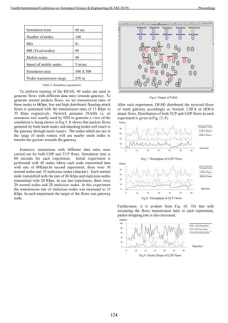
![IV. CONCLUSION AND FUTURE WORK
In WMNs, mesh gateways are mostly susceptible to
DDOS attacks. Numerous techniques are proposed to detect
distributed flooding attack in WMNs, but still there is a need
of an intelligent security mechanism to avoid the influence of
intruders on WMNs. An intelligent mechanism based on
ANN, is being proposed in this paper to classify incoming
flows at gateway into three different categories. Simulations
results verified that DFAD is efficient and precise in
classifying the incoming flows. In future, DFAD will
differentiate flash crowd form attack flows. Moreover, we will
also identify and trace back source of the ongoing distributed
flooding attack.
ACKNOWLEDGEMENT
The authors extend their gratitude to the Research Centre,
Institute of IT, Kohat University of Science & Technology and
the Higher Education Commission of Pakistan, for funding
this research work.
REFERENCES
[1] S. Khan, K. K. Loo, and Z. Din, "Framework for intrusion
detection in IEEE 802.11 wireless mesh," International Arab
Journal of Information Technology, vol. 7, no. 4, pp. 435-439,
2010.
[2] D. Benyamina, A. Hafid, and M Gendreau, "Wireless mesh
networks design — a survey," IEEE Communications Surveys &
Tutorials, vol. 14, no. 2, pp. 299-310, 2011.
[3] F. Xing and W. Wang, "Understanding dynamic denial of
service attack in mobile ad hoc networks," in IEEE Military
communication conference (MILCOM), 2006.
[4] H. Beitollahi and G. Deconinck, "Analyzing well-known
countermeasures against distributed denial of service attacks,"
Computer Communications, vol. 35, no. 11, pp. 1312–1332,
2012.
[5] B B Gupta, Joshi, and Manoj , "Distributed denial of service
prevention echniques," International Journal of Computer and
Electrical Engineering, vol. 2, no. 2, pp. 268-276, 2010.
[6] K Reyhaneh and F Ahmad, "An anomaly-based method for ddos
attacks detection using rbf neural networks," International
Conference on Network and Electronics Engineering IPCST,
vol. 11, pp. 44-48, 2011.
[7] Thwe Thwe Oo and Thandar Phyu, "A statistical approach to
classify and identify DDoS Attacks using UCLA dataset,"
International Journal of Advanced Research in Computer
Engineering & Technology (IJARCET), vol. 2, no. 5, pp. 1766-
1770, 2013.
[8] D. J. Jingle and E. B. Rajsingh, "Defending IP spoofing attack
and TCP SYN flooding attack in next generation multi-hop
wireless networks," International Journal of Information &
Network Security (IJINS), vol. 2, no. 2, pp. 160-166, 2013.
[9] Thwe Thwe Oo and Thandar Phyu, "DDoS detection system
based on a combined data mining approach," 4th International
Conference on Science and Engineering, pp. 315-319, 2013.
[10] G. Wang, J. Hao, J. Ma, and L. Huang, "A new approach to
intrusion detection using artificial neural," Expert Systems with
Applications, vol. 37, no. 9, pp. 6225-6232, 2010.
[11] S. Khan and K. K Loo, "Real-time cross-layer design for large-
scale flood detection and attack traceback," Network Security,
vol. 23, no. 5, pp. 9-16, 2009.
[12] D. Novikov, R. V. Yampolskiy, and L. Reznik, "Artificial
intelligence approaches for intrusion," in IEEE Long Island
Systems, Applications and Technology Conference (LISAT
2006), Long Island, NY, 2006.
[13] E. Gelenbe, "Learning in the recurrent random neural network,"
Neural Computation, vol. 5, no. 1, pp. 154–164, 1993.
[14] S. M. A. Burney, M. S. A. Khan, and Dr. T. A. Jilani, "Feature
deduction and ensemble design of parallel neural networks for
intrusion detection system," International Journal of Computer
Science and Network Security (IJCSNS), vol. 10, no. 10, pp.
259-267, 2010.
[15] G. OKE and G. Loukas, "A denial of service detector based on
maximum likelihood detection and the random neural network,"
The Computer Journal, vol. 50, no. 6, pp. 717-727, 2007.
[16] B. B. Gupta and R. C. Misra,M. Joshi, "ANN based scheme to
predict number of zombies in a DDOS attack," International
Journal of Network Security, vol. 14, no. 2, pp. 61-70, 2012.
[17] The network simulator - ns-2 web page,"http://nsnam.isi.edu/
nsnam/index.php/Main_Page".
Time(Sec)
Packets
HDFA-Pkt.Drop.Rate
LDFA-Pkt.Drop.Rate
Normal-Pkt.Drop.Rate
Fig.10. Packet Drops of UDP flows
125
Fourth International Conference on Aerospace Science & Engineering (ICASE 2015) Proceedings](https://image.slidesharecdn.com/conferenceproceedingsicase2015final1-160918062150/85/Conference-proceedings-134-320.jpg)
![Touch Panel Based Modern Restaurants Automation
using Zigbee Technology
1,*
Aamir Nawaz,2
Faiz Jalil
Institute of Engineering & Technology
Gomal University
DIKhan, Pakistan
1
engr.aamir09@gu.edu.pk
2
fj_kulachvi@yahoo.com
Abstract
In present scenario, automation is in high demand.
Management of present restaurants and hotels are much
dependent on manpower. This project deals with automation
of restaurants with wireless touch panel based menu systems.
This project reduces manpower required for taking order from
customers. Full menu of all restaurant’s eatable items are
displayed on touch panel for selection. Customers have to put
their orders through touch panels which will be received in
kitchen without any interaction of waiters. Zigbee has been
used for wireless link between touch panels of kitchen and
restaurant tables. PIC microcontroller has been used for
coding of menu display on touch panel and transmitting and
receiving on zigbee modules. Project has been implemented
and tested in software such as Proteus 8. Furthermore,
hardware implementation has been done on PCB layout. By
using embedded system with wireless Technology whole
procedure will built. The order from selected table number go
to server then serve items to selected table customer .We can
speed up the serving and attract customer with non – volatile
memory capable of retaining data for over ten years .By
dumping the code in microcontroller ISP is used
Index Terms—Zigbee, Restaurant automation, Micrcontroller
I. INTRODUCTION
Restaurant business is one of the most profitable
businesses. Therefore, the importance of food serving is of
great significance. Over the years, food and the relative job of
serving has grown so much that need for facilitation and
automation has been increased. industries. Nowadays, when
profit is the prime concern and its measurement has increased
from million to billions, every bit is done to increase profit.
We have made an effort to bring technology into the dining
menu of customers. This research aims to not only improve the
business of restaurants but also to incorporate the essence of
science in dining menu.
Arun in [1], implemented a train anti-collision and level
crossing system based on zigbee technology. He has created
four modules which are train system module, control center
system module, signaling post system module and level
crossing at gate module. He has simulated proposed system in
Proteus electronic simulation package.
Ramasamy [2] has proposed a fire avoiding system on
running train. In his proposed system, train driver will know in
case of fire in any section of train and stop it instantly to take
necessary action.
In [3], Blaho proposed a zigbee wireless network to control
speed and other parameters of train model. He has created m-
files and Simulink environment which can be used for teaching
purposes.
In [4], Vinodhini proposed a restaurant system for two way
ordering system. He has provided table of customer with touch
screen and kitchen with liquid color display (LCD). He has
used ARM cortex M3 for simulation.
In [5], Wang has introduced zigbee technology for
establishing wireless sensor networks (WSN) and its
applications in industry and home appliances.
Bhargave in [6], has introduced a system for restaurant
using android technology. He proposed integration of Order
System Kitchen Order Ticket (KOT), Billing System and
Customer Relationship Management System (CRM).
Implementation of such integration has increased quality and
speed of restaurant service.
Wahab in [7], has presented a new development in
restaurant ordering system. He built up network system
integration for connecting customer table with management
panel. He used microcontroller with VB and RS 232
communication port. Proposed system performed well in
network based system.
The proposed system will have a complete Touch Panel
device in restaurants and hotels that will help to reduce the
human interaction and save time. This project implements a
system that is on customer table by having touch panel menu
ordering system. We have one touch technology by selecting
the items from menu list display in LCD on customer table
The basic concept of the project is to reduce human effort
for the customers and also to deliver them with best facilities.
Wireless communication link between customer’s table and
kitchen has been established for placing order on customer’s
side and verifying it on kitchen side. Furthermore, bill details
126
Fourth International Conference on Aerospace Science & Engineering (ICASE 2015) Proceedings](https://image.slidesharecdn.com/conferenceproceedingsicase2015final1-160918062150/85/Conference-proceedings-135-320.jpg)

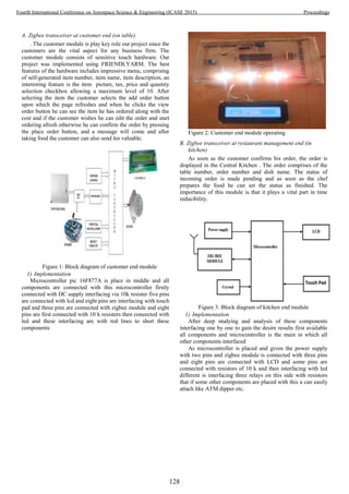
![Figure 4: Kitchen end module operational
V. COMPARISON OF PROPOSED SYSTEM WITH PREVIOUS
SYSTEMS
Table 1 shows comparison results on the basis of different
features considered for comparison. For comparison, Pixel
point [9], LRS[10], Eric software[8] and Smart order system[7]
are considered. As it can be seen that proposed system
outperforms all other systems in comparison.
TABLE 1. COMPARISON OF PROPOSED SYSTEM WITH PREVIOUS SYSTEMS
Features Pixel point LRS Eric soft Smart order system Proposed System
Graphics NO NO NO NO YES
ATM Sweeper NO NO NO NO YES
Prices NO NO NO NO YES
Group Orders NO NO NO YES YES
Status of Ordering NO NO NO NO YES
Wireless Network YES YES YES NO YES
Touch Screen YES NO YES NO YES
VI. SIMULATION AND RESULT EXPLORATION
In restaurant, customer’s table module has a touch screen
display in which menu is shown. When this menu is pressed,
full menu of restaurant eatables are shown on screen to be
selected. Once order is selected and forwarded to kitchen, it
uses zigbee transmitter and receiver to deliver that information
to kitchen. Kitchen module will receive order which will be
displayed on LCD. Kitchen person will confirm order by
pressing confirm button or reject any unavailable eatable items
from menu. Then, customer will get information regarding
unavailability of any items and can re-order. Furthermore,
waiter can be called by pressing “Call waiter” button.
The proposed system can be used with line following
robots or conveyer belts to deliver order till customers. This
will reduce more human effort as there will be no waiter
required to deliver order to tables. Other benefits are:
Provision of facility for handling text electronically using
powerful processors to produce elegant and error free
documents.
In addition to storing the organization’s operational data
on disk drive for back up.
With the installed software, product ordering and delivery
was made easier.
The systematic approaches used during each phase of the
software development provides a clear road map that
would be of immense help to anyone carrying out research
work in this area.
VII. CONCLUSION
This research contributes to recent working environment of
restaurants and can change it from previous manual system to
an automated restaurant with a lot of facilities to customers as
well as restaurant management. Furthermore, it will be helpful
in attracting customers to see and avail such facilities. Zigbee ,
as a wireless link between customer’s table and kitchen can be
replaced by any other wireless technologies for larger
restaurants which supersedes zigbee’s range of communication.
Line following robots or conveyer belts can be used to deliver
eatable items to customers instead of waiters.
REFERENCES
[1] Arun P., Sabarinath G., “Implementation of ZigBee based Train
Anti -Collision And Level Crossing Protection System for
Indian Railways." Int. J. of Lat. Trends in Eng. and Tech., Vol.2,
pp: 12-18, January, 2013.
129
Fourth International Conference on Aerospace Science & Engineering (ICASE 2015) Proceedings](https://image.slidesharecdn.com/conferenceproceedingsicase2015final1-160918062150/85/Conference-proceedings-138-320.jpg)
![[2] R. P. Ramasamay, M. P. Kumar, S. S. Kumar, R. R. Raman,
“Avoidance of fire accident on running Train using ZigBee
Wireless Sensor Network”, Int. J. of Inform. and Comp. Tech.,
Vol.3, pp: 583-592, 2013.
[3] M. Blaho, J. Ozimy, M. Ernek, M. Foltin, “Zigbee
implementation in Railroad model”.
[4] B. Vinodhini, K. Abinaya, R. Roja, M. Rajeshwari, “Wireless
Two-way Restaurant Ordering System via Touch Screen”,
Vol.3, pp: 01-05, 2014.
[5] W. Wang, G. He, J. Wan, “Research on Zigbee wireless
communication technology”, Int. Conf. on Elect. and Cont. Eng.
(ICECE), 2011.
[6] Bhargave, A., Jadhav, N., Joshi, A., Oke, P., & Lahane, M. S.
(2013). “Digital Ordering System for Restaurant Using
Android”, International Journal of Scientific and Research
Publication, Vol.3, 2013.
[7] Wahab, M. H. A., Kadir, H. A., Ahmad, N., Mutalib, A. A., &
Mohsin, M. F. M. (2008, August).” Implementation of network-
based smart order system”, International Symposium on
Information Technology, 2008. ITSim 2008. (Vol. 1, pp. 1-7).
IEEE.
[8] .[8] M.H.A. Wahab, H.A. Kadir, N. Ahmad, A.A. Mutalib and
M.F.M. Mohsin, “Implementation of network-based smart order
system,” International Symposium on Information Technology
2008
[9] PAR PixelPoint “PixelPoint POS Brochure [Accessed: 11 May
2011]
[10] Advanced Analytical, Inc (October 2004) “LRS Restaurant
Server Pager”, [Accessed: 11 May 2011]
130
Fourth International Conference on Aerospace Science & Engineering (ICASE 2015) Proceedings](https://image.slidesharecdn.com/conferenceproceedingsicase2015final1-160918062150/85/Conference-proceedings-139-320.jpg)
![Introducing space plant biology to students through
hands-on activities using clinostat
Ferheen Ayaz
SUPARCO Institute of Technical Training, HR Dte Gen,
Space and Upper Atmosphere Research Commission,
Karachi, Pakistan
ferheen@msn.com
Qurat-ul-Ain
SUPARCO Institute of Technical Training, HR Dte Gen,
Space and Upper Atmosphere Research Commission,
Karachi, Pakistan
ain_haider@hotmail.com
Abstract—Space biology is an important topic for research
and education in order to explore future life in space. Plant
growth and development largely depends upon gravitational
acceleration on earth. The growth process of a plant in space is
significantly different from that on earth due to the absence of
gravity, which is referred as zero gravity or microgravity. One-
axis clinostat simulates microgravity environment on earth. On a
horizontal clinostat, an object is rotated perpendicular to the
force of gravity. Although the gravity is present on an object
rotated by clinostat, its continuous reorientation nullifies the net
effect of gravitational acceleration. One-axis/horizontal clinostat
is a useful tool for space education. The simulated microgravity
created by the clinostat, despite its limitations, causes significant
changes in plant growth which may lead to introduce school and
college level students about plant life in space and creating their
interest in space biology. This paper describes some of the
experiments conducted on one axis clinostat, by a group of
teachers and students of SUPARCO Institute of Technical
Training, which proved to be a fruitful activity resulting in
learning of gravitropism basics of plants and seeds. The article is
aimed towards helping the educators in creating hands-on
learning activities for students to have an idea about life in space
by making use of facilities available on earth. The orientation of
roots grown from radish seeds (Raphanus sativus), area and
length of roots and shoots grown from pea seedlings (Pisum
sativum), length and bending angle of shoots of Marigold plant
(Tagetes patula) and growth rate and direction of wheatgrass
(Thinopyrum intermedium) were observed on the clinostat. The
roots of radish seeds did not grow downwards in the direction of
gravity but oriented themselves at random angles on the
clinostat. Pea seedlings also showed different growth rates on
clinostat as compared to their growth on earth. The experiment
on Marigold plant resulted in faster growth in length and larger
bending angle of clinorotated plant shoots as compared with
stationary plant shoots. The growth rate of wheatgrass on earth
and on clinostat was nearly same but their bending angles were
different in both conditions. All the experiments provoked the
minds of students to make inferences on seeds and plants growth
in space. The experiments described in the paper create
inquisitiveness among teachers and students to observe many
other parameters in plant growth under microgravity.
Keywords—clinostat; gravitropism; microgravity
I. INTRODUCTION
Considering the long term goals of space agencies and
seeking habitation of extraterrestrial surfaces; one of the
important concerns is to analyze the development of plants in
space. The reason behind this concern is the dependence of
plants and animals upon each other for their survival and
flourishing of ecosystem [1]. Study of plant growth in space is
different from conventional plant growth on earth mainly
because of the fact that it is greatly influenced by gravitational
acceleration. Recent experiments in space have resulted in
modified growth rates of roots and shoots of different plants
and the major reason of this modification is the absence of
gravity in space [2].
In order to promote space exploration related activities and
establish plant life in space, one of the key initiatives is to
promote space education among young students. Creating
interest of students in space sciences may lead to increase their
curiosity towards exploring life support systems in space and
planetary surfaces. Due to limited facilities of space research
in underdeveloped countries, students are least interested in
space biology. The students are less inclined to study space
sciences because of unavailability of resources and
opportunities to do practical work in this field. The practical
work for science students plays a very important role in their
learning [3]. As it is difficult to create practical setups of
complete space environment on earth, establishing a simulated
microgravity environment can provide excellent practical
opportunity for researchers and students to study life sciences
and plant and animal life in space [4].
Fig. 1. One-axis clinostat to simulate microgravity on earth.
Microgravity for a very short period of time can be created
on earth by elevator, drop tower, rocket and aircraft [5] but
changes in plant growth cannot be observed by these methods
as their growth process is comparatively slower. The efficient
instruments for conducting biology experiments in simulated
131
Fourth International Conference on Aerospace Science & Engineering (ICASE 2015) Proceedings](https://image.slidesharecdn.com/conferenceproceedingsicase2015final1-160918062150/85/Conference-proceedings-140-320.jpg)
![microgravity environment are 2D and 3D clinostats [6].
Keeping in view the practical needs of space education,
SUPARCO (Space and Upper Atmosphere Research
Commission) Institute of Technical Training acquired 2D
clinostat, as shown in Fig. 1, under ZGIP (Zero Gravity
Instrument Project) initiated by United Nations Human Space
Technology Initiative (HSTI) in 2013. A 2D or one axis
clinostat has one rotational axis which rotates perpendicular to
the direction of gravity vector in order to create the effect of
microgravity and is suitable for studying the behavior of
germinating seeds and analyzing plant growth [7]. Although
horizontal clinostat does not completely create zero gravity
environment on the object under study [8], it can still be used
for educational purposes to demonstrate changes in plant
growth by alteration of gravity.
This article describes some experiments conducted on
seeds and plants using clinostat at SUPARCO Institute of
Technical Training by a group of 2 instructors and 10 students
aged between 17 to 19 years. The objective of describing the
experiments is to promote science teachers and students to
study space biology practically and to provoke the minds of
interested learners to bring up similar but new ideas to
experiment and discover effects of gravity on plants.
The organization of the rest of the paper is as follows:
Section II describes the experiments performed using
clinostat, Section III discusses results of the experiments and
conclusion is mentioned in Section IV.
II. EXPERIMENTS PERFORMED USING CLINOSTAT
A. The radish seeds
The first experiment to study gravitropism on the roots of
radish seeds (Raphanus sativus) was conducted as described in
[7]. Nine samples of radish seeds were placed on each of the
three Petri dishes. The Petri dishes were half filled with agar-
agar solution to aggravate the process of germination.
Humidity, temperature and light conditions were kept same for
each Petri dish. After 48 hours, when the roots started to grow
downward, first Petri dish was placed vertically with roots
along the direction of gravity, second was turned 90o
so that
the roots were held perpendicular to the gravity vector and the
third was attached to clinostat using double sided tape. The
rotation disc of clinostat was held horizontally. The placement
of Perti dishes is illustrated in Fig. 2. The clinostat was set to
rotate with a speed of 10 r.p.m. for 4 hours and photographs of
each Petri dish were captured using a digital camera. After the
experiment, the photographs were observed using Image J
software. The orientation of roots was analyzed in terms of
angle created as the roots bent during the experiment.
Fig. 2 (a). First Petri dish with roots parallel to gravity vector.
Fig. 2 (b). Second Petri dish with roots perpendicular to gravity vector.
Fig. 2 (c). Third Petri dish attached to clinostat.
B. The pea seedlings
This experiment was designed by the working group to
observe not only the roots, but also the shoots grown from pea
seeds (Pisum sativum). Four test tubes were half filled with the
agar-agar solution made by the procedure defined in [7]. A pea
seed was placed inside each test tube such that it lies exactly
in the middle of the tube as shown in Fig. 3. After 7 days, the
shoots and roots of the pea seeds were grown. Two test tubes
were placed horizontally perpendicular to the gravity vector
and the other two test tubes were attached to clinostat. The
132
Fourth International Conference on Aerospace Science & Engineering (ICASE 2015) Proceedings](https://image.slidesharecdn.com/conferenceproceedingsicase2015final1-160918062150/85/Conference-proceedings-141-320.jpg)


![was 0.118 cm/hour from Day1 to Day2, 0.026 cm/hour
from Day2 to Day3 and 0.024 cm/hour from Day 3 to
Day4. It was almost the same on clinostat. The
calculations came out to be 0.112 cm/hour from Day1
to Day2, 0.027 cm/hour from Day2 to Day3 and 0.026
cm/hour from Day 3 to Day4.
As shown in Fig. 8(b); on earth, the wheatgrass grew
almost straight and angles with respect to the direction
of gravity were in the range of 0 to ±3o
, showing
almost no bending. On clinostat, the angles were
varying in the range to 10o
to 14o
which is the evident
proof of bending.
Summary of the result is presented in Table IV.
TABLE IV. LENGTH AND ANGLE OF WHEATGRASS DRUING 5 DAYS OF
EXPERIMENT
Measurement
of:
Average Length (cm) Average Angle
(degrees)
Day On earth
On
clinostat
On earth
On
clinostat
1 3.69 2.30 0.931 13.73
2 6.54 5.00 -0.69 8.77
3 7.19 5.67 2.81 10.80
4 7.77 6.31 -2.44 8.39
Fig. 8(a). Length of wheatgrass per day on earth and on clinostat.
Fig. 8(b). Angle of wheatgrass per day on earth and on clinostat.
IV. CONCLUSION
Four experiments on different seeds and plants were
conducted on clinostat. The results show that all plants do not
exhibit similar behavior in microgravity. Absence of gravity
speeded up the growth rate in pea seedlings and Marigold
plant but did not influence wheatgrass. The diversity of the
experiments described in this article encourages the students
to try out experiments on other plants and seeds available to
them. Various other parameters like temperature, humidity,
type of soil, amount of water and nutrients provided can also
be modified to discover new effects of gravity and
microgravity on plants.
Acknowledgment
The study is carried out as a part of Zero Gravity
Instrument Project initiated by United Nations Office for
Outer Space Affairs (UNOOSA). We gratefully acknowledge
UNOOSA for donating clinostat, Training Division, HR Dte
Gen, Pakistan Space and Upper Atmosphere Research
Commission for their coordination in publishing the article
and Horticulture Cell, Pakistan Space and Upper Atmosphere
Research Commission for assisting in plant growth.
References
[1] R. Ferl, R. Wheeler, H. G. Levine, and A. L. Paul, “Plants in space.”
Current opinion in plant biology, vol. 5, no. 3, 2002, pp. 258-263.
[2] T. Hoson, “Plant growth and morphogenesis under different gravity
conditions: Relevance to plant life in space,” Life, vol. 4, no. 2, 2014,
pp. 205-216.
[3] V. N. Lunetta, A. Hofstein, and, M. P. Clough, “Learning and teaching
in the school science laboratory: An analysis of research, theory, and
practice,” Handbook of research on science education, 2007, pp. 393–
441.
[4] A. Niu, M. Ochiai, and H. J. Haubold, “The United Nations Human
Space Technology Initiative (HSTI): Science Activities,” IAC-12-
A2.5.11, 2012.
[5] M. J. Rogers, G. L. Vogt, and M. J. Wargo, “Microgravity: A Teacher's
Guide with Activities in Science, Mathematics, and Technology,”
NASA, EG-1997-08-110-HQ, 1997.
[6] M. Cogli, “The fast rotating clinostat: a history of its use in gravitational
biology and a comparison of ground-based and flight experiment
results,” Gravitational and Space Research, vol. 5, no. 2, 2007.
[7] “Programme on Space Applications: Teachers Guide to Plant
Experiments in Microgravity,” United Nations Office for Outer Space
Affairs, 2013.
[8] A.H. Brown, O.A. Dahl, and D.K. Chapman, “"Limitation on the use of
the horizontal clinostat as a gravity compensator," Plant Physiology, vol
58, no. 2, pp. 127-130, 1976.
Sponsored by Pakistan Space and Upper Atmosphere Research
Commission.
135
Fourth International Conference on Aerospace Science & Engineering (ICASE 2015) Proceedings](https://image.slidesharecdn.com/conferenceproceedingsicase2015final1-160918062150/85/Conference-proceedings-144-320.jpg)

![Helium is the element
with the smallest
molecular size
Used for Leak detection
Has extremely low
solubility in water
Used as a diving gas
Helium-3 is not
radioactive
Used as a heat transfer
medium in fusion reactors
The importance of the noble gas being realized, it is
important to mention that there is a shortage of Helium on
Earth. Currently, Helium supplies are obtained from the
extraction of natural gas. The United States produces about
75% of the world’s Helium and roughly 30% of the world’s
Helium supply comes from the US federal Helium reserve. The
problem is that Helium reserves are being depleted at a rapid
rate because of wide use of the gas. Walter Nelson, director of
helium sourcing for Air Products and Chemicals Inc. predicts
the usable life of the US reserves to last till 2018-2020. This
will have a global impact, especially on healthcare and small-
scale scientific research. MRI machines need Helium to
operate and they will become difficult to maintain with a
shortage of Helium, ultimately making it very difficult to
obtain MRI’s.
Furthermore, Harrison Schmitt, a geologist and astronaut, is
of the opinion that Helium-3 can prove to be a very useful
alternative for deuterium and tritium in nuclear fusion reactors
for power generation, as the reaction involving Helium-3 does
not result in the emission of neutrons, making it clean and non-
polluting.
Since there are not enough supplies on the Earth to provide
the Helium-3 needed to carry out commercial power generation
through fusion, in his book “Return to the Moon” Harrison
Schmitt argues that the moon should be mined for Helium-3.
Since the moon is continuously bombarded with solar wind, it
has a large amount of Helium-3, though in small
concentrations of about 10-20 parts per billion. Schmitt
outlines a plan to for mining helium-3 on the Moon to feed a
commercial industry for generating power, though it will be
very expensive.
Even if many consider Schmitt’s proposal to be unrealistic,
it is a fact that he is not the only one who thinks mining the
moon for Helium-3 is a good idea; The leader of Beijing's
space program, has said generating power via nuclear fusion
using He-3 could "solve energy demand for 10,000 years at
least". So China is seriously considering it.
B. Rare Earth Elements
Rare Earth Elements, or REE for short, are 17 elements in
the periodic table which are widely used in electronics. Their
name tends to be misleading; they are relatively plentiful in the
earth’s crust. [11]
The mining of REE was once dominated by the United
States from 1965 to 1985, until The People’s Republic of
China started dominating the market. In 2010, a “Rare Earths
Trade Dispute” occurred, with China on one side and many
other countries, especially the US, on the other [10]. China had
increased the restrictions on its exports of REE by reducing its
export quota by 40% [2][12]. This resulted in a major increase
in the prices of REE outside the country. Although the Chinese
government argued that the reduction in the quota was for the
benefit of the environment (REE mining is highly polluting),
critics were unconvinced. Due to the importance of the REE in
the military, the question arose in the US of supply
vulnerability of these elements [2][13]. There were also
accusations that China had banned the exports of REE to Japan
after the 2010 Senkaku boat collision incident. The matter of
the Chinese restrictions was brought to the Dispute Settlement
Body of the WTO in 2012, by the United States. China had
joined the WTO in 11 December 2001. When it joined the
WTO, China signed an accession treaty, which did not allow
such restrictions on exports unless the goods in question were
stated, which was not the case here. China defended itself by
arguing that article XX (b) of the GATT allowed exceptions if
the restrictions were put in place for the protection of human,
animal or plant life or health. The majority of the panel was of
the view that the exceptions in article XX (b) did not justify
China’s reduction of export quotas and that these measures
were not necessary for the protection of human, animal or plant
life or health in this case. So the WTO ruled against China in
2014 and the country removed the restrictions in 2015 [10].
There are rocks rich in Potassium, REE, and Phosphorous
along with other elements, referred to as KREEP, on the
moon’s surface. According to the deputy director of the Rock
Mechanics and Explosives Research Centre at the Missouri
University of Science and Technology in Rolla, Leslie
Gertsch, although REE themselves aren’t detectable on the
moon’s surface, KREEP is. Detection of components of
KREEP, such as Thorium, on the lunar surface helps locate
associated REE due to similar geochemical properties that
caused them to crystallize under the same conditions, Gertsch
says. Dale Boucher, director of innovation at the Canada-based
Northern Centre for Advanced Technology Inc., in Sudbury,
Ontario, stated that the feasibility of mining REE on the moon
can only really be judged after exploration intended for this
exact purpose. It is difficult to assess it otherwise, as there are
many factors which determine its feasibility, including cost of
separating REE obtained from ores from each other, cost of
transportation of said REE, cost of refining them etc. (North
America seems to have abundant REE deposits but it is just not
profitable to mine them). But it is still in the realm of
possibilities. If a country does indeed intend to mine REE from
the moon’s surface in the near future, there’s a risk that a
scenario similar to the Rare Earths Trade Dispute might occur
C. Colonization
The United States, Japan, and Russia have shown interest in
the establishment of colonies on the moon [16]. The plans
seemed to have gained more ground on November 13, 2009,
137
Fourth International Conference on Aerospace Science & Engineering (ICASE 2015) Proceedings](https://image.slidesharecdn.com/conferenceproceedingsicase2015final1-160918062150/85/Conference-proceedings-146-320.jpg)
![when NASA announced the discovery of ice caps at the south
pole of the moon [15].
The reasons given by NASA for the exploration of the moon
are:
1. Human Civilization: Extend human presence to the
Moon to enable eventual settlement
2. Scientific Knowledge: Pursue scientific activities that
address fundamental questions about the history of
Earth, the solar system and the universe; and
therefore, about our place in them
3. Exploration Preparation: Test technologies, systems,
flight operations and exploration techniques to reduce
the risks and increase the productivity of future
missions to Mars and beyond
4. Global Partnerships: Provide a challenging, shared
and peaceful activity that unites nations in pursuit of
common objectives
5. Economic Expansion: Expand Earth's economic
sphere, and conduct lunar activities with benefits to
life on the home planet
6. Public Engagement: Use a lively space exploration
program to engage the public, encourage students and
help develop the high-technology workforce that will
be required to address the challenges of tomorrow
[3][4][5]
The 1st
and 3rd
reasons show their intention to colonize the
moon in the future. In January 2012 Republican candidate for
President of the United States of America, Newt Gingrich,
proposed the establishment of a US moon colony by 2020,
though the plan faced much criticism.[16]
Russia’s intentions seem to be different regarding the 3rd
reason. “The Moon is not an intermediate point in the race; this
process has the beginning, but has no end. We are going to the
moon forever.” stated Russia’s Deputy PM Dmitry Rogozin
who is in charge of space and defense industries. In 2007, the
Soviet Union announced its plan to establish a permanent
moon base by 2025 [14]. The main focus seems to be lunar
tourism [16]. According to a government draft that Izvestia, a
Russian newspaper, claims to have obtained, Russia has a 3-
step plan for manning the moon [14][17]:
1. Sending a robotic craft to the moon, possibly as early
as 2016,
2. Sending manned missions to orbit the moon by 2028,
3. A base will be set up by 2030, using resources from
the moon.
Japan announced its plans of setting up a moon base in
2006. They estimated that the base in question will be
established by 2030. Their main motivation, they claim, is the
development of robotics. [9]
D. Future Missions of Major Parties:
[20]
1. United States (NASA)
a. Exploration Mission-1: An unmanned flight
of the Orion (MPCV), using NASA’s Space
Launch System (SLS). The aim will be to
qualify the Heavy Lift Launch Vehicle (HLV)
and Beyond Earth Orbit (BEO) Orion for
transportation of humans into deep space. The
estimated date of launch is December 17,
2017. The mission is expected to last 7-10
days [18].
b. Exploration Mission-2: The first manned
mission of NASA’s BEO. The crew will
consist of 4 people. The aim will be to test
Orion’s life support systems and to validate
its crew operations. The mission is expected
to be carried out by the year 2021 [19].
2. Russia (ROSCOSMOS)
a. Luna-25: To land on the South Pole of the
moon, and test the lander technology and
communications systems
b. Luna-26: To orbit the moon for detailed
mapping of the moon’s surface and search for
a new landing site for future missions and to
measure the lunar atmosphere.
c. Luna-27: To go to the south pole of the moon
for testing drilling systems and analyzing
contents.
d. Luna-28: To return soil samples to the earth
e. Luna-29: To use a rover to take samples from
different locations on the moon’s surface
[21][22][23][24][25]
3. China
a. Chang’e 4: A backup probe for Chang’e 3
[6], which put which put a lander and the
Jade Rabbit rover on the moon in 2013. The
expected year of launch is 2020. [26][28]
b. Chang’e 5: To return lunar samples [27][29]
c. Chang’e 6: A backup for Chang’e 5. [27]
4. Japan (JAXA)
An attempt at Japan’s first lunar landing, an
unmanned flight, is planned for 2019, though the
budget for the plan is not available yet. [30][31][32]
5. India (ISRO)
Chandrayaan-2: Terrain mapping by the employment
of new technology for better imaging of the lunar
surface.
138
Fourth International Conference on Aerospace Science & Engineering (ICASE 2015) Proceedings](https://image.slidesharecdn.com/conferenceproceedingsicase2015final1-160918062150/85/Conference-proceedings-147-320.jpg)
![[33][34]
6. European Union (ESA)
ESA plans to send a lander near the moon’s South
Pole in 2018. The purpose of the mission is to probe
the moon’s surface and to test new technologies for
future landings.[7]
7. Private
Google Lunar X Prize: Astrobotic Technology, a
privately held American company, plans on launching
a private launcher in 2015, with the aim of winning the
Google Lunar X Prize, which was created in 2017 to
encourage space entrepreneurs to create a new era of
affordable access to the Moon and beyond. [8]
E. Conclusion
As it can be vividly seen, there are several detailed and
ambitious projects ready to explore the moon and benefit from
its resources. Keeping that in mind it becomes more important
than ever to firmly establish policies right now that are
acceptable to all parties to avoid any conflicts in the future.
ASTEROID MINING
Besides the moon, asteroids also have potential resources
which scientists are looking to explore.
Most asteroids in the solar system are found between Mars
and Jupiter. This region is termed the asteroid belt or main belt.
Asteroids with orbits that bring them within 1.3 AU (121
million miles/195 million kilometres) of the Sun are known as
Earth-approaching or near-Earth asteroids (NEAs). These are
the asteroids which people are looking to mine. Most or all
asteroids found in the main belt appear to be NEAs.
Asteroids are usually categorized according to their albedo
(how reflective they are), composition derived from spectral
features in their reflected sunlight, and inferred similarities to
known meteorite types.
There are 3 main categories:
1. C-type (carbonaceous): More than 75% of known
asteroids belong to this category.
Albedo: 0.03-0.09
Composition: Thought to be similar to the sun’s
composition, except for the absence of hydrogen, helium and
other volatile elements and compounds. Because of their low
temperatures, they are estimated to contain up to 22% water.
Found in: the main belt’s outer region.
2. S-type (silicaceous): About 17% of known asteroids
belong to this category.
Albedo: 0.10-0.22
Composition: metallic iron mixed with iron- and
magnesium-silicates.
Found in: the main belt’s inner region.
3. M-type (metallic):
Albedo: 0.10-0.18
Composition: mainly metallic iron.
Found in: the main belt’s middle region.
[35]
A. Motivations for Asteroid Mining
Based on consumption rates in both developed and
developing countries, it is estimated that terrestrial reserves of
elements needed for modern industry will be exhausted within
50–60 years. Consequently, 44 elements are expected to face
supply limitations in the coming years, including phosphorus,
antimony, zinc, tin, silver, lead, indium, gold, and copper. All
these elements are crucial for industry [36][37][38]. Some of
the applications of a few of these elements are noted in the
following table:
TABLE 2.ELEMENTS FROM ASTEROIDS AND MAJOR APPLICATIONS
Element Applications
Copper . Used in electrical equipment
such as wiring and motors.
. Copper Sulfate is used as an
agricultural poison and as an
algaecide in water purification.
. Fehling’s solution, a solution
containing copper, and other
copper containing solutions are
used in chemistry for qualitative
analysis.
. Copper alloys are used in
making coins.
Zinc . Used to galvanize objects to
prevent rusting.
. Used to produce die-castings.
. Used in alloys such as brass,
nickel silver and aluminum
solder.
. Zinc oxide is used in the
manufacture of paints, rubber,
cosmetics, pharmaceuticals,
plastics, inks, soaps, batteries,
textiles and electrical equipment.
. Zinc sulfide is used in making
luminous paints, fluorescent lights
139
Fourth International Conference on Aerospace Science & Engineering (ICASE 2015) Proceedings](https://image.slidesharecdn.com/conferenceproceedingsicase2015final1-160918062150/85/Conference-proceedings-148-320.jpg)
![and x-ray screens.
Lead . Used for car batteries, pigments,
ammunition, cable sheathing,
weights for lifting, weight belts
for diving, lead crystal glass,
radiation protection and in some
solders.
. Used to store corrosive liquids.
. Used in architecture, for roofing
and in stained glass windows.
Tin . Used to coat other metals to
prevent corrosion.
. A niobium-tin alloy is used for
superconducting magnets.
. Tin salts sprayed onto glass are
used to produce electrically
conductive coatings.
[39]
B. Mining Considerations
There are three options when considering mining asteroids:
1. Bringing the raw material to earth.
2. Processing the raw material on the asteroid itself and
then bringing the processed material to earth.
3. Transport the asteroid to a safe orbit around the
Moon, Earth or to the ISS. This method is estimated to be the
one which allows the most materials to be used.
[40][41]
C. Proposed Mining Projects
There are four main parties currently proposing projects for
mining asteroids:
1. NASA (US)
An upcoming mission, termed OSIRIS-Rex, scheduled for
launch in 2016, will involve travelling to a near-Earth asteroid
called Bennu and bringing a small (about 60g) sample back to
Earth for study. The destination will be reached in 2018 and the
sample will be transported to the earth in 2023.[49][50]
NASA Institute for Advanced Concepts (NIAC) announced
the Robotic Asteroid Prospector (RAP) project on in
September 2012. The purpose of RAP is to evaluate the
feasibility of asteroid mining in terms of means, methods, and
systems. Their stated strategy is: “Initial prospecting missions
will be robotic, although early industrial mining missions will
require both humans and robots on-site. There will be too many
judgment calls and qualitative decisions on-site for robots
alone. Humans will need the practice of mining in space with
robots to learn how to innovate and to work efficiently,
reliably, and safely.” [42]
2. Planetary Resources (Private, US)
The company announced on April 24, 2012 its plans to
mine NEA. They plan to launch prospective spacecraft for
collecting data about asteroids within 7 years. The company
plans to build new technology which will reduce the price of
space travel so that it can be successful in its mission.
[46][47][48]
4. Deep Space Industries (Private, US)
On January 22, 2013, this private company announced its
plans to launch spacecraft in 2015 for prospecting suitable
asteroids and returning samples to the earth, and to begin
mining NEA by 2023. [43][44][45]
5. Kepler Energy and Space Engineering (KESE)
They aim to build and send a 4-module Automated Mining
System (AMS) to a small asteroid with a simple digging tool to
collect approximately 40 tons of samples by the end of the
decade, using existing guidance, navigation and anchoring
technologies.[51]
D. Conclusion
It becomes clear after looking at the motivations and future
plans of various parties (countries as well as private parties)
that a future marathon for space resources is highly probable.
Unfortunately, the Outer Space and Moon Treaty hinder the
steps made towards the mentioned endeavours as they face
many legal barriers. For now, only the hurdles provided by the
outer space treaty will be discussed, as the moon treaty has not
been signed by major influential parties. Specific parts of the
two treaties will be discussed in more detail later on in the
paper.
Based in part on the Antarctic Treaty, the Outer Space
Treaty only appears to permit research activities on the moon
and other celestial bodies, though this is debatable. “The idea
that you can't claim sovereignty is not necessarily incompatible
with the right to go conduct mining operations. The high seas
are not subject to any sovereignty, but people can go and fish
there.” said international lawyer and space-law expert Timothy
Nelson in an interview with space.com, referring to an article
in the 1967 treaty stating: “Outer space, including the moon
and other celestial bodies, is not subject to national
appropriation by claim of sovereignty”.
Even then, the treaty hinders research, mainly owing to a
lack of incentive. Due to the statement that no particular party
can claim any ownership rights to the resources, there will be a
lack of commercial concern, ultimately leading to a lack of
funding for research, hence lowering the amount of potential
research which can be carried out.
140
Fourth International Conference on Aerospace Science & Engineering (ICASE 2015) Proceedings](https://image.slidesharecdn.com/conferenceproceedingsicase2015final1-160918062150/85/Conference-proceedings-149-320.jpg)
![HISTORICAL ANALYSIS
The ever-evolving economic landscape presents a unique
challenge in the world of politics. The one of keeping peace
and making sure that the resources of a state are not
illegitimately taken away from it. The solution is an old one;
treaties and organizations to enforce the treaties.
In this section conflicts and resources as a main reason for
conflicts will be discussed, along with how they can be
avoided. This will lead to the importance of treaties in the
international landscape and through the analysis of treaties and
treaty organizations a parallel will be drawn between the
historic treaties and conflict and the current space situation to
show that the current treaties governing space exploration and
resources management are not viable.
A. Wars
History has seen many wars fought over resources. Hitler’s
campaign in 20th century, before the Second World War is a
perfect example of a war fought over resources. When Hitler
came to power in 1933 his whole agenda centered on making
Germany a powerful sovereign country again. There were two
important aspects to this. One was regaining areas with great
economic potential, such as Alsace and Loraine on the western
border; they were highly industrialized zones and had Iron ore
and Coal deposits. Another was to get more land. This was a
part of Lebensraum (literally ‘living space’), a German
ideology proposing expansion to give more space to the
German people. This generally advocated expansion on the
Eastern front. [52]
Another event is the period in history known as the
“Scramble for Africa” between 1881 and 1914. It is the period
of invasion, occupation, colonization and annexation of
African territories by European empires. Africa had a lot of
natural resources, ranging from coal to diamonds, and a huge
untapped potential. Furthermore the African population was
also used as a source of free labor through slavery. As
expected, with such resources available, it was not long before
war broke out, not only the war against the natives to take
control of the area, but also between different European powers
to get the biggest piece of the pie. [53]
The most recent, and one that is still relevant today, is of
the Oil War. Oil war is the term given to all the conflicts over
petroleum resources. Oil has become very important in the
modern world, as primary source of energy its significance is
unprecedented. Petroleum resources alone can run a country’s
economy such as the Middle East states, while on the other
hand import of oil can cripple a country. The result of all this is
that oil became an extremely important resource in the
international landscape, a resource that countries wage wars
over. There have been a number of conflicts over oil [54]. The
Iran-Iraq war (1980-1988), the Gulf War (1990-1991) and the
Afghan War (1978-present) are major examples of this. Some
conflicts that have control of petroleum resources as an ulterior
motive are still present today. The most recent major crisis was
Russia’s annexation of Ukraine, this not only demonstrates
Russia’s interest in controlling the oil pipeline routes, but also
that of United States [55]. And perhaps the most important is
the creation of ISIS. ISIS sits on an oil rich land, and even
though no state can legally buy oil from them, they do have a
steady income through oil sales. This location of ISIS and the
possible effect of their oil sales made it important to other
foreign powers even before they began global terrorism.
[56][57].
As it can be seen, resources are an impetus for war. And as
the previous section elaborated, space has a lot of resources
available and a space race between various parties is highly
probable. Whereas history shows, there is an equally high
probability of conflict as a result of this. And in order to avoid
this we need a comprehensive treaty system.
B. A Failed Treaty
As with anything else, it is important to learn from the
mistakes already made by others. The same goes with treaties.
It is crucial to see where the previous treaties went wrong and
to rectify them. In hope of avoiding future conflicts from
turning violent and it is of immense importance when
considered that now the domain of humans is not just restricted
to the Earth, but also includes the space.
The Treaty of Versailles of 1919 is one of the most
important treaties ever signed. It effectively brought an end of
the First World War, though unknown at the time it was
signed, it was a significant factor in the start of the Second
World War. [58]
The treaty’s ultimate failure was when Germany invaded
Poland in 1939, dragging the whole of Europe into the Second
World War. There were a number of reasons for the failure of
the treaty. One was that the treaty had been made by the
winners of the war and it was very profitable for them i.e. it
was a biased treaty where everyone was not on the table. The
treaty was generally against one country (Germany) and the
actors at the time felt that as long as one rogue state was
controlled, the peace would not be disturbed, but in reality
limitations were needed for all the countries. Another reason
was that there was no way to reinforce the terms of the treaty,
such as the clauses that called for all-around disarmament.
None of the countries wanted to reduce armaments, so no one
was there to enforce the decision either. And whereas countries
like Britain and France had agreed to keep Germany in check,
they were not ready to go to war for it or even impose sections
that would hurt their own economy. Hence it can be seen that
the ultimate weakness of the treaty was that there was no one to
stop any country from breaking it.[52]
Most of these reasons are generic, and very similar reasons
lie behind the failure of almost all treaties. And so when
planning for the future, especially in the case of forming
141
Fourth International Conference on Aerospace Science & Engineering (ICASE 2015) Proceedings](https://image.slidesharecdn.com/conferenceproceedingsicase2015final1-160918062150/85/Conference-proceedings-150-320.jpg)
![treaties that have universal importance, like as those related to
the space, such weaknesses in treaties of the past should be
avoided. A few of the common shortcomings that must be
avoided are the treaty should not be directed against just a
certain country or to control just the rogue states, but be
equally applied to everyone; furthermore the treaty needs to
absolutely binding, and the powerful states that promise to
direct it, must be legally compelled to do. And most
importantly there should be measures that make it impossible
for states to violate or ignore the treaty.
C. A Failed Organization
An organization created along with Treaty of Versailles
was the League of Nations. It was the predecessor to the United
Nations. It had two main aims, one to maintain international
peace through “collective security” and the second to promote
international cooperation to solve social and economic
problems. [59] The former was the more important function of
the body. The world had just come out of the First World War,
and sought peace and stability. The main idea was to discuss
the problems as they rose, and solve them through an
understanding of all the countries through a unanimous effort.
Though the League looked very good on paper, it was not so
successful in reality, with the Second World War an epitome of
its failure. There are a number of reasons why the organization
failed. Firstly it did not include all the countries, major
exclusions were the US, Germany, and USSR. And there were
serious weaknesses in the covenant, like unanimous decisions
were needed and the League had no force of its own. The result
was that it could advise on how to solve problems, but it could
not force a state. Furthermore it was a very British and French
affair; these were the two most powerful countries at the time
and the league was always under their control. As a result the
League was prone to letting allies of the major states get away
with anything; major examples of this are the Japanese
invasion of Manchuria (1931) and the Italian invasion of
Abyssinia (1935). [52]
Once again it is important to take care of these few
parameters in order to form a comprehensive organization that
would be much more equipped to deal with problems in a
manner that would avoid conflict. The “Regime” is an
organization was proposed by the Moon Treaty to for the use
of the Moon and other celestial bodies, and it is yet to be
formed. Keeping the weaknesses of past organizations in mind,
especially those that led to the failure of the League of Nations,
the framework of the Regime should be such that it covers all
states equally and does not hinder it in its function, yet allows
it to be decisive. All countries should get a say in it, but
decisions should not be unanimous as it would render it
impractical, and similarly it should not give powerful states the
veto power, as it too could hinder the organization.
D. A Successful Treaty
Antarctica is the closest example of space on Earth.
Antarctica, like space, has no native inhabitants. This makes
the Antarctica Treaty System immensely important. Signed in
1959, the treaty established a few ground rules for every state
regarding Antarctica. First off the geographical area of
Antarctica was determined. And it was agreed that the area will
be used for peaceful purposes only. Freedom of scientific
investigation and cooperation was guaranteed. And importantly
it prohibited new territorial sovereignty claims, but did not
dispute nor recognize the old claims. [60]
Further additions were made to the initial treaty, among
them, the most important was the Convention on the
Regulation of Antarctic Mineral Resource Activities (1988),
which made mining illegal in Antarctica even though there coal
deposits and hydrocarbons along with other minerals [61]. And
the Protocol on Environmental Protection to the Antarctic
Treaty (1991) was to insure the protection of the Antarctic
environment and ecosystem.[62]
The Antarctic treaty has been a success so far. It has
managed to peacefully promote Antarctica as a research area
and kept it from being militarized. And it has also successfully
prevented any conflicts over territory by not recognizing or
disputing preexisting claims, and forbidding new claims.
Furthermore the environment of Antarctica has been protected
and it remains the only continent that has not been affected by
the human population.
The Antarctic Treaty has been successful, however that
does not make it a perfect model to work with in terms of a
space treaty. Unlike Antarctica, outer space is not a small
potential contributor to world’s demands for mineral resources.
Moreover, outer space also does not pose any environment
threats to Earth like industrialization of Antarctica could.
Furthermore, research in space might very well soon depend on
extraction and utilization of space resources to fuel it. Yet on
the other hand, the Antarctic Treaty has prevented conflict in
the region in an exemplary way, and the features of the treaty
that guaranteed this should be replicated which will be
discussed latter.
The current treaties are inspired by the Antarctic Treaty but
success cannot be replicated this way since the conditions are
far too different. As a result, the UN must recognize the
difference to move forward to full utilization of outer space’s
potential, yet in such a manner that global peace is not
jeopardized.
FLAWS IN THE TREATIES
A. The Res Communis Controversy
One of the chief controversies is the Res Communis
ideology employed especially in the Moon Treaty 1979 [65].
The phrase “common heritage of mankind” contributes to the
overall vagueness of the treaty and hence fuels the insecurity of
interested nations. Since moon and celestial objects are a
“province of mankind” [66], any form of active military
involvement is forbidden. However, considering the rise of
terrorist organizations like ISIS and rogue nations like North
142
Fourth International Conference on Aerospace Science & Engineering (ICASE 2015) Proceedings](https://image.slidesharecdn.com/conferenceproceedingsicase2015final1-160918062150/85/Conference-proceedings-151-320.jpg)
![Korea, both increasingly using sophisticated technology; it
seems dubious that space would remain untainted from terrorist
activities in the future.
In the case of USA, however, the reasons for disagreement
were political. The treaty put developed countries in a place
where they or their private companies could be attacked for
using outer space resources by developing countries. This
concerned scientists, entrepreneurs and politicians alike as it
not only meant a decreased interest in outer space by the
government and private groups but also a resulting decline of
space science research because if the moon and celestial bodies
are to remain unusable, then there is little incentive for them to
work.
It is true, however, that it could be done under the watch of
an “international regime” [67] but that too raises the fear of
blackmail since non-space-faring countries are in a majority
and most likely to lobby themselves to obtain economic
advantages. It is expected that the “international regime” would
be similar to “The Enterprise” proposed in Agreement of the
Law of the Sea Convention 1994[68]. The Enterprise, by its
very nature, was to receive a portion of wealth obtained by the
parties exploiting marine resources and distribute it amongst
developing countries. Such a system could prove discouraging
for space resources as there is a much higher capital required
and much greater risk of failure, combining this with low
profits means that space resources may remain untouched for a
long time even after sufficient technology has been developed.
Outer Space Treaty enforced the idea that no state could
claim any region in space [69], however it was not very
specific about private companies and groups. But the Moon
Treaty attempted to make sure that even private groups could
not lay claim to any region in space. As expected, it raised a lot
of opposition from the business community and it became one
of the most controversial points of the treaty.
B. Property and Ownership
It has been agreed that ownership of space and celestial
objects is not possible for countries but there is an apparently
silent approval for private groups. This raises further questions
and controversies.
Firstly, how can the ownership be declared if there is no
national government to maintain and uphold the rights of the
property owner. Such a situation would force the owners to
establish their own system of defense which may lead to an
arms race or recurring physical conflict in space.
As it is later suggested, the establishment of an organization
like “The Enterprise” is critical. Moreover, the UN should be
prepared to accept the eventual necessity of a peace-keeping
force in space to assist the organization in enforcement of its
mandate.
C. Lack of Space Involvement
On the other end of the spectrum, another hurdle in
development of sustainable space policies is a lack of
awareness and interest by some countries stemming from a
lack of space involvement. These countries often have not
developed a significant space involvement and hence deem the
development of such policies to be pointless in the present, as
the delegate of Argentina replied to COPUOS question
regarding definition of Outer Space: “The present magnitude of
space and aviation activities and technologies has not given
rise to a need for the adoption of specific provisions delimiting
outer space [70]”.
Though Argentina has CONAE as its space agency, its
future plans, however, do not include any form of space
exploration, simply satellite management [71], unlike countries
like China, Japan, USA, Russia and India as elaborated in
Section II. The case of Argentina is not singular but it
represents the hesitation of many countries that have too weak
space involvement to be able to make decisions concerning
their role in it. Hence to play it safe they decide not to indulge
in the process of any policy making which they may find even
slightly restrictive in the future.
Consequently, a large number of developing and some
developed countries are not a part of policy making because
their national experts and politicians do not have the
knowledge and understanding of the importance and
significance of space policy making, especially those
pertaining to resources because since Moon and celestial
bodies have been declared a common heritage of mankind it is
important that all countries understand their resulting rights and
limitations
D. Confidentiality and Privacy
The Moon Treaty states “…all space vehicles, equipment,
facilities, stations and installations on the moon shall be open
to other States Parties…” [72]This could give rise to a lot of
possible misuses and controversies such as technology theft,
infringement of privacy and right to confidentiality.
If it is possible for any state to inspect the equipment of any
other state then it is possible that this may be used to replicate
the technology of the first state. It poses many questions about
the right of having intellectual properties in space. Even though
countries and private groups may accept space as a common
heritage but it will be unfair for them to lose the rights to all
their individual research and development in space. Since such
research is extremely expensive, it is very likely that such a
jurisdiction would very severely dent the interest in it.
Parties operating in space and celestial bodies will also
have to disclose the specifics of their activities even though
they may be well within their rights. It too opens up debate on
human rights, among other things. If, for example, a researcher
is studying the health of astronauts on moon, he may have to
disclose data regarding this research, which may contain
personal information of astronauts. This can be taken as a
violation of Universal Declaration of Human Rights [73].
E. Lack of Violation Protocols
Both the treaties fail to outline a mechanism that is to be
followed if the treaties are breached by a country. United
Nations would most likely be unable to undertake any legal or
physical action since the Security Council would need
143
Fourth International Conference on Aerospace Science & Engineering (ICASE 2015) Proceedings](https://image.slidesharecdn.com/conferenceproceedingsicase2015final1-160918062150/85/Conference-proceedings-152-320.jpg)
![unanimous votes to do so. As a result the treaties appear to
restrict less influential and less powerful countries only, since
the stronger ones can easily get off without any rebuttal as they
can diplomatically procure a veto.
The example of Antarctic Treaty needs to be considered
here [74]. Interestingly enough, Antarctic treaty was the
inspiration for Outer Space treaty and yet such an integral
component was left out. According to Antarctic Treaty, in case
there is a clash of purposes between two parties, the matter can
be taken into International Court of Justice from where the
matter could be resolved. Not only does it safeguard the
integrity of the treaty but it also makes it more trustable, one of
the many reasons of its success.
The two treaties were missing a core element of a
successful international agreement, the violation protocols and
as it was witnessed with the failure of Moon Treaty, other
articles are meaningless without them.
F. Stifling Space Research and Funding
It is true that Outer Space Treaty intends to maximize
research and interest in outer space; however, its actual effects
have been different. As it has been previously established, the
restrictions collectively work to discourage investors. This in
turn leads to a direct decrease in the funding of researchers and
scientists who are researching on space related areas. Apart
from nationally run agencies, few research groups are able to
sustain themselves. Consequently, the research that has been
done is nowhere near the research that could have been done
without the policies.
If some of the most restrictive clauses are removed, there
would be an immediate rise in research, jobs, interest and
awareness regarding space and celestial bodies. Space is an
area that captures the imagination of many young scientists but
they are often unable to find employment or even advanced
education in their area of interest.
SOLUTIONS
A. Establishment of Extraction-Friendly Framework
The current policies need to be modified to encourage both
the private and government space agencies to attempt
extraction of resources from regions beyond Earth. To that end,
several changes need to be made.
Private parties should be allowed to have at least temporary
property rights so their reservations about lack of control can
be met. It makes sense to allow property rights on, for example,
asteroids, because after the extraction is over there will be little
left of it.
Parties should also have a greater degree of privacy and
confidentiality. Specific rules and regulations should be framed
to ensure that the rights to intellectual property and personal
privacy of astronauts are conserved.
Moreover the specifics of a regime like “The Enterprise”
for space should be discussed and decided. Special attention
should be given in making sure that space agencies are not
restricted unfairly by the share they have to provide to such a
regime.
The shares from the extraction should be based on a model
such that small scale extraction is bound to a lesser percentage
and large scale extraction to a greater percentage.
B. Increasing Space Awareness
Established agencies like the NASA should work harder to
develop a sense of understanding and importance of space
resources and hence the importance of policy making
governing it.
Only after the governments and experts of individual
nations realize the significance of such policies and how they
are critical in avoiding future clashes can the UN as a whole
move forward.
It may also be important to get international public support
for the policies to pressurize the governments into making
decisions in the present than letting them hang on for the
future. This requires the use of education and awareness
mechanisms through television, newspapers and public talks.
C. International Space Property Rights
Due to the sheer enormity of space, abundance of celestial
bodies and rapid shifting, it may never be possible to divide
regions of space in a manner that is fair to all. However, the
common heritage ideology may prove extremely impractical in
the future. As an analysis of history shows, such a concept is
extremely naïve when considered alongside the thousands of
wars that people have waged for land and resources.
Space agencies, both private and government, need to have
a tangible incentive for them to risk a great amount of capital
and manpower in attempting to reach for the moon and beyond.
Loss of the right to ownership can discourage space
exploration. They should be entitled to own, use and sell the
resources that they have extracted, to at least some degree.
However, concerns of developing nations should also be
addressed pertaining to property rights. Their current reduced
state of development does not mean that they lose any chance
of being a part of the future.
Taking both sides into consideration, one method that
seems feasible is to employ a procedure whereby regions of
space are provided as property only during the period they are
being actively used by the party to discourage gluttony.
.
D. Developing Violation Protocols
To uphold the good intentions, enforce articles and develop
trust, there needs to be a strong and independent system of
justice which ensures that the rights of less powerful and less
influential countries remain preserved.
To that end, a section of the International Court of Justice
could be formed to deal with space law. However, for its
smooth operation the policies need to be much more detailed.
In fact, it would be wise to draw up an internationally
acceptable constitution governing activities in space and
celestial objects. Not only would it act as a code of conduct for
144
Fourth International Conference on Aerospace Science & Engineering (ICASE 2015) Proceedings](https://image.slidesharecdn.com/conferenceproceedingsicase2015final1-160918062150/85/Conference-proceedings-153-320.jpg)
![parties interested in space resource extraction but would also
help quickly resolve any minor conflicts that may arise.
E. Using International Diplomacy Positively
Moon Treaty was treated very coldly by the international
community. However, an active interest of a single party such
as the USA could have totally reshaped its outcome as the
decisions of such influential nations are followed by their close
allies as well. In fact, an agreement on an international issue
between USA, China and Russia almost always gains nearly
unanimous global support.
As a result bloc leaders like USA and China should take a
responsive and positive role in the development of space
policies. By considering the interests of their allies, many of
those who do not have an independent space program, they can
help shape a globally acceptable and beneficial treaty.
REFERENCES
[1] [Online] Available: www.islandone.org/Treaties/BH766.html
[2] Leonard David. (2010, October 4). Is Mining Rare Minerals on
the Moon Vital to National Security? [Online]. Available:
http://sservi.nasa.gov/articles/is-mining-rare-minerals-on-the-
moon-vital-to-national-security/
[3] Beyond Earth [Online]. Available:
http://www.nasa.gov/exploration/home/why_moon.html
[4] (December 2006). Lunar Exploration Objectives
(1sted.)[Online]. Available:
http://www.nasa.gov/pdf/163560main_LunarExplorationObjecti
ves.pdf
[5] [Online]. Available: http://www.permanent.com/lunar-mining-
the-moon.html
[6] (2013, December 16). China plans to launch Chang'e 5 in 2017
[Online]. Available:
http://news.xinhuanet.com/english/china/2013-
12/16/c_132971252.htm
[7] (2010, September 16). NEXT STEP FOR ESA’S FIRST
MOON LANDER [Online]. Available:
http://www.esa.int/Our_Activities/Human_Spaceflight/HSF_Dir
ectors_Corner/Next_step_for_ESA_s_first_Moon_lander
[8] [Online]. Available: http://lunar.xprize.org/
[9] (2003, August 3). Japan Plans Moon Base By 2030 [Online].
Available:
http://www.moondaily.com/reports/Japan_Plans_Moon_Base_B
y_2030_999.html
[10] China — Measures Related to the Exportation of Rare Earths,
Tungsten and Molybdenum [Online]. Available:
https://www.wto.org/english/tratop_e/dispu_e/cases_e/ds431_e.
htm
[11] Kieran Mulvaney. (2012, March 14). The Fight Over Rare
Earths: A Primer [Online]. Available:
http://news.discovery.com/earth/the-fight-over-rare-earths-a-
primer-120314.htm
[12] Lesley Stahl. (2015, March 22). Modern life’s devices under
china’s grip?[Online]. Available:
http://www.cbsnews.com/news/rare-earth-elements-china-
monopoly-60-minutes-lesley-stahl/
[13] Leonard David. (2010, October 4). Is Mining Rare Minerals on
the Moon Vital to National Security? [Online]. Available:
http://www.space.com/9250-mining-rare-minerals-moon-vital-
national-security.html
[14] (2014, May 9). Russia will begin Moon colonization in 2030 -
draft space program [Online]. Available:
http://rt.com/news/157800-russia-moon-colonization-plan/
[15] Pat Cahill. (2014, January 20). Mount Holyoke professor Darby
Dyar says a colony on the moon is no fantasy [Online].
Available:
http://www.masslive.com/living/index.ssf/2014/01/mount_holyo
ke_professor_part_of_massive_study_of_outer_space.html
[16] DeAnnaKerley. 15 Ambitious Plans to Colonize the Moon
[Online]. Available: http://mentalfloss.com/article/53588/15-
ambitious-plans-colonize-moon
[17] Anna Dolgov. (2014, May 8). Russia Plans to Colonize Moon
by 2030, Newspaper Reports [Online]. Available:
http://www.themoscowtimes.com/article/499806.html
[18] Chris Bergin. (2012, February 29). Exploration Mission 1: SLS
and Orion mission to the Moon outlined [Online]. Available:
http://www.nasaspaceflight.com/2012/02/exploration-mission-1-
sls-orion-debut-mission-moon-outlined/
[19] Chris Bergin. (2012, October 30). EM-2: Orion crew to spend
up to four days in Lunar Orbit [Online]. Available:
http://www.nasaspaceflight.com/2012/10/em-2-orion-crew-
spend-four-days-lunar-orbit/
[20] Future planetary missions [Online]. Available:
http://spaceexp.tumblr.com/future-missions
[21] Russian Moon missions face three-year delay [Online].
http://www.russianspaceweb.com/spacecraft_planetary_2014.ht
ml
[22] (2014, October 10). SRI: Russia will begin launching automatic
stations to the Moon in 2018 [Online]. Available:
http://ria.ru/space/20141003/1026822990.html#ixzz3eXhKtcXA
http://ria.ru/space/20141003/1026822990.html
[23] Russian Lunar Polar Probes, 2015-2020 [Online]. Available:
http://www.permanent.com/russian-lunar-polar-probes.html
[24] (2014, August 3) Manned Moon Mission to Cost Russia $2.8
Bln – Space Research Institute [Online]. Available:
http://sputniknews.com/russia/20140803/191677434.html#ixzz3
eXiSLeokhttp://sputniknews.com/russia/20140803/191677434.h
tml
[25] (2014, October 10) Russian Luna-25 Mission to Cost Billions:
Space Agency [Online]. Available:
http://sputniknews.com/russia/20141010/193919188.html#ixzz3
eXj6Nr00http://sputniknews.com/russia/20141010/193919188.h
tml
[26] (2015, May 22). China Plans First Ever Landing On The Lunar
Far Side [Online]. Available:
http://www.spacedaily.com/reports/China_Plans_First_Ever_La
nding_on_the_Dark_Side_of_the_Moon_999.html
[27] Leonard David. (2015, March 17). China Outlines New Rockets,
Space Station and Moon Plans [Online]. Available:
http://www.space.com/28809-china-rocket-family-moon-
plans.html
[28] Alexandra Witze. (2014, March 19). China's Moon rover awake
but immobile [Online]. Available:
http://www.nature.com/news/china-s-moon-rover-awake-but-
immobile-1.14906
[29] Bradley Perret. (2013, December 16). China Plans 2017 Lunar
Sample-Return Mission [Online]. Available:
http://aviationweek.com/space/china-plans-2017-lunar-sample-
return-mission
[30] (2015, April 19). JAXA plans Japan’s first moon shot in 2018
[Online]. Available:
http://www.japantimes.co.jp/news/2015/04/19/national/jaxa-
plans-japans-first-moon-shot-in-2018/#.VY5YSruqqkp
[31] Dianne Depra. (2015, April 4). Japan Aiming For Moon
Landing By 2018 According To JAXA [Online]. Available:
http://www.techtimes.com/articles/48266/20150424/japan-
aiming-for-moon-landing-by-2018-according-to-jaxa.htm
[32] (2015, April 22). JAPAN TO ATTEMPT UNMANNED
LUNAR LANDING IN 2018 [Online]. Available:
http://www.spaceflightinsider.com/organizations/jaxa/japans-
jaxa-to-attempt-lunar-landing-in-2018/
145
Fourth International Conference on Aerospace Science & Engineering (ICASE 2015) Proceedings](https://image.slidesharecdn.com/conferenceproceedingsicase2015final1-160918062150/85/Conference-proceedings-154-320.jpg)
![[33] (2010, Sep 5). ‘We’re launching Chandrayaan-2 for a total
coverage of the moon’ [Online]. Available:
http://timesofindia.indiatimes.com/home/opinion/interviews/We
re-launching-Chandrayaan-2-for-a-total-coverage-of-the-
moon/articleshow/6501413.cms?referral=PM#
[34] India to launch Chandrayaan-2 by 2017 [Online]. Available:
http://www.thehindu.com/sci-tech/science/india-to-launch-
chandrayaanii-by-2017/article5562361.ece?ref=sliderNews
[35] Asteroids [Online]. Available:
http://nssdc.gsfc.nasa.gov/planetary/text/asteroids.txt
[36] Stephen Shaw. (2012, August 21). Posts Tagged ‘C-type
asteroids’ Asteroid Mining [Online]. Available:
http://www.astronomysource.com/tag/c-type-asteroids/
[37] Endangered Elements [Online]. Available:
http://www.acs.org/content/acs/en/greenchemistry/research-
innovation/research-topics/endangered-elements.html
[38] David Cohen. (2007, May 23). Earth's natural wealth: an audit
[Online]. Available:
http://www.sciencearchive.org.au/nova/newscientist/027ns_005.
htm
[39] Periodic Table [Online]. Available: http://www.rsc.org/periodic-
table/
[40] Stephen Harris. (2013, April 8). Your questions answered:
asteroid mining [Online]. Available:
http://www.theengineer.co.uk/aerospace/in-depth/your-
questions-answered-asteroid-mining/1015966.article
[41] (2012, April 2). Asteroid Retrieval Feasibility Study [Online].
Available:
http://kiss.caltech.edu/study/asteroid/asteroid_final_report.pdf
[42] Marc Cohen. Robotic Asteroid Prospector (RAP) Staged from
L-1: Start of the Deep Space Economy [Online]. Available:
http://www.nasa.gov/offices/oct/early_stage_innovation/niac/20
12_phase_I_fellows_cohen.html
[43] Mike wall. (2013, January 22). Asteroid-Mining Project Aims
for Deep-Space Colonies [Online]. Available:
http://www.space.com/19368-asteroid-mining-deep-space-
industries.html
[44] (2013, January 22). Commercial Asteroid Hunters announce
plans for new Robotic Exploration Fleet [Online]. Available:
http://www.prweb.com/releases/2013/1/prweb10346181.htm
[45] Taylor Soper. (2013, January 22). Deep Space Industries
entering asteroid-mining world, creates competition for
Planetary Resources [Online]. Available:
http://www.geekwire.com/2013/deep-space-industries-entering-
asteroidmining-world-creates-competition-planetary-resources/
[46] http://www.planetaryresources.com/technology/#space-based-
observation
[47] (2012, April 24). Company aims to mine resource-rich asteroids
[Online]. Available:
http://lightyears.blogs.cnn.com/2012/04/24/companies-plan-to-
mine-precious-metals-in-space/?hpt=hp_t3
[48] (2012, April 24). Plans for asteroid mining emerge [Online].
Available: http://www.bbc.com/news/science-environment-
17827347
[49] (2013, August 8). New NASA Mission to Help Us Learn How
to Mine Asteroids [Online]. Available:
https://www.nasa.gov/content/goddard/new-nasa-mission-to-
help-us-learn-how-to-mine-asteroids
[50] (2015, June 22). OSIRIS-REx Team Prepares for Next Step in
NASA’s Asteroid Sample Return Mission [Online]. Available:
https://www.nasa.gov/feature/goddard/osiris-rex-team-prepares-
for-next-step-in-nasa-s-asteroid-sample-return-mission
[51] Michael Buet and Robert Frantz. ASTEROID MINING: WHY
AND HOW? [Online]. Available:
http://www.friendsofbest.org/wp-
content/uploads/2015/05/ASTEROID-MINING_WHY-AND-
HOW-Article_03.pdf
[52] Norman Lowe, Mastering Modern World History, 4th edition,
New York: Palgave Macmillan, 2007
[53] Andrina Stiles, "Bismark's Germany" in The Unification f
Germany, 1st edition, London, England: Hodder& Stoughton,
1998, pp. 85-99
[54] John Lowe and Robert Pearce, "Colonial Rivalries, 1870-1914"
in Rivalry and Accord - International Relations 1870-1914, 1st
edition, London, England: Hodder& Stoughton, 2007, pp. 39-69
[55] Michael Klare, The Race for What's Left: The Global Scramble
for the World's Last Resources, 1st edition, New York: Picador,
2013.
[56] Dr. Nafeez Ahmed. (2014, March 6), Ukraine crisis is about
Great Power oil, gas pipeline rivalry [Online]. Available:
http://www.theguardian.com/environment/earth-
insight/2014/mar/06/ukraine-crisis-great-power-oil-gas-rivals-
pipelines
[57] Keith Johnson. (2014, September 24), U.S. Strikes ISIS Oil
Installations [Online]. Available:
http://foreignpolicy.com/2014/09/24/u-s-strikes-isis-oil-
installations/
[58] Treaty of Versailles, Paris, 28 June 1919, League of Nations
Treaty Series, available from
https://en.wikisource.org/wiki/Treaty_of_Versailles
[59] Covanent of League of Nations, available at
https://en.wikisource.org/wiki/Covenant_of_the_League_of_Nat
ions
[60] Antarctic Treaty, Washington, 1 December 1959, available from
http://disarmament.un.org/treaties/t/antarctic/text
[61] Environmental Treaties and Resource Indicators (ENTRI),
Available
From:http://sedac.ciesin.columbia.edu/entri/texts/acrc/cramra.txt
.html
[62] Protocol on Environmental Protection to the Antarctic Treaty,
1991, available from
http://www.antarctica.ac.uk/about_antarctica/geopolitical/treaty/
update_1991.php
[63] Outer Space Treaty, Washington DC, 10 October 1967,
available from
http://www.unoosa.org/oosa/en/ourwork/spacelaw/principles/leg
al-principles.html
[64] Moon Treaty, New York, 18 December 1979, available from
http://www.unoosa.org/oosa/en/ourwork/spacelaw/treaties/moon
-agreement.html
[65] Para 1, Article 11, Agreement Governing the Activities of States
on the Moon and Other Celestial Bodies, United Nations, 1979
[66] Article 1, Treaty On Principles Governing The Activities Of
States In The Exploration And Use Of Outer Space, Including
The Moon And Other Celestial Bodies, United Nations, 1967
[67] Para 5 -7, Article 11, Agreement Governing the Activities of
States on the Moon and Other Celestial Bodies, United Nations,
1979
[68] Part XI, Agreement of the Law of the Sea Convention, United
Nations, 1994
[69] Article 2, Treaty On Principles Governing The Activities Of
States In The Exploration And Use Of Outer Space, Including
The Moon And Other Celestial Bodies, United Nations, 1967
[70] A/AC.105/889/Add.14, Committee on the Peaceful Uses of
Outer Space, United Nations General Assembly
[71] CONAE website : http://www.conae.gov.ar
[72] Para 1, Article 15, Agreement Governing the Activities of States
on the Moon and Other Celestial Bodies, United Nations, 1967
[73] Article 12, Universal Declaration of Human Rights,1948
[74] Para 2 Article 11, The Antarctic Treaty, 1959
146
Fourth International Conference on Aerospace Science & Engineering (ICASE 2015) Proceedings](https://image.slidesharecdn.com/conferenceproceedingsicase2015final1-160918062150/85/Conference-proceedings-155-320.jpg)
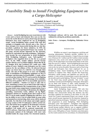


![MATERIAL PROPERTIES
For analysis, material properties of CFRP were
calculated. To have symmetric properties in all the three
direction, Quasiisotropic (0, 90, +45, and 45)Figure 7: Stacking
Sequence sequence was selected as stacking sequence for our
material
Figure 7: Stacking Sequence
To find out the properties of CFRP, “ANALYSIS
AND DPERFORMAANCE OF FIBRE CCOMPOSISTEES”,
written by BHAGWWAN D. AGAARWWAL was concerned,
in CFRP carbon is fiber while epoxy was as matrix, following
calculations were carried out
The expression for elastic modulus is as
𝐸𝑐 = 𝐸𝑓 𝑉𝑓 + 𝐸 𝑚 𝑉𝑚
We have
𝐸𝑓 = 220 𝐺𝑃𝑎
𝐸 𝑚 = 3.54𝐺𝑃𝑎
𝑉𝑓 = 0.5
𝑉𝑚 = 0.5
By putting these values
𝐸𝑐 = 220 ∗ 0.5 + 3.54 ∗ 0.5
𝐸𝑐 = 112 𝐺𝑃𝑎
Now to find out elastic modulus in other two direction
𝐸 𝑇
𝐸 𝑚
=
1 + Ƹƞ𝑉𝑓
1 − Ƹƞ𝑉𝑓
ƞ =
𝐸𝑓
𝐸 𝑚
⁄ − 1
𝐸𝑓
𝐸 𝑚
⁄ + Ƹ
Putting values in above eqn we get
ƞ = .95
𝐸 𝑇 = 17.61 𝐺𝑃𝑎
Similarly 𝐺 𝐿𝑇 becomes
𝐺 𝐿𝑇 = 3.60 𝐺𝑃𝑎
To find out the elastic modulus we will find out the A
matrix for above sequence
For this we need Q matrix for each ply
𝑄 = [
𝑄11 𝑄12 𝑄16
𝑄21 𝑄22 𝑄26
𝑄61 𝑄62 𝑄66
]
𝑄11 =
𝐸𝐿
1 − 𝑣 𝐿𝑇 𝑣 𝑇𝐿
𝑄11 = 134.5 𝐺𝑃𝑎
𝑄22 =
𝐸 𝑇
1 − 𝑣 𝐿𝑇 𝑣 𝑇𝐿
𝑄22 = 17.7 𝐺𝑃𝑎
𝑄12 = 4.619 𝐺𝑃𝑎
𝑄66 = 𝐺 𝐿𝑇 = 3.69 𝐺𝑃𝑎
The Q matrix becomes for 0 deg ply becomes
𝑄 = [
134.5 4.6 0
4.6 17.75 0
0 0 3.6
]
For lamina at any angle the Q matrix becomes
𝑄̅ = [
𝑄̅11 𝑄̅12 𝑄̅16
𝑄̅21 𝑄̅22 𝑄̅26
𝑄̅61 𝑄̅62 𝑄̅66
]
Above values can be calculated from eqns as follows
𝑄̅11 = 𝑄11 𝑐𝑜𝑠4
𝜃 +𝑄22 𝑠𝑖𝑛4
𝜃 + 2(𝑄12
+ 2𝑄66) 𝑠𝑖𝑛2
𝜃 𝑐𝑜𝑠2
𝜃
𝑄̅22 = 𝑄11 𝑠𝑖𝑛4
𝜃 +𝑄22 𝑐𝑜𝑠4
𝜃 + 2(𝑄12
+ 2𝑄66) 𝑠𝑖𝑛2
𝜃 𝑐𝑜𝑠2
𝜃
𝑄̅12 = 𝑄12(𝑐𝑜𝑠4
𝜃 + 𝑠𝑖𝑛4
𝜃) + (𝑄11 + 𝑄12
− 4𝑄66) 𝑠𝑖𝑛2
𝜃 𝑐𝑜𝑠2
𝜃
𝑄̅66 = 𝑄66(𝑐𝑜𝑠4
𝜃 + 𝑠𝑖𝑛4
𝜃) + (𝑄11 + 𝑄22 − 2𝑄12
− 2𝑄66) 𝑠𝑖𝑛2
𝜃 𝑐𝑜𝑠2
𝜃
𝑄̅66 = (𝑄11 − 𝑄12 − 2𝑄66 )𝑐𝑜𝑠3
𝜃 sin 𝜃 + (𝑄22 − 𝑄12
− 2𝑄66) 𝑠𝑖𝑛3
𝜃 cos 𝜃
𝑄̅66 = (𝑄11 − 𝑄12 − 2𝑄66 )𝑠𝑖𝑛3
𝜃 cos 𝜃 + (𝑄22 − 𝑄12
− 2𝑄66) 𝑐𝑜𝑠3
𝜃 sin 𝜃
Q matrix for 45 deg lamina becomes
𝑄̅ = [
44.14 36.76 29.09
36.76 43.96 29.09
29.09 29.09 3.6
]
150
Fourth International Conference on Aerospace Science & Engineering (ICASE 2015) Proceedings](https://image.slidesharecdn.com/conferenceproceedingsicase2015final1-160918062150/85/Conference-proceedings-159-320.jpg)
![Q matrix for -45 deg lamina becomes
𝑄̅ = ⌈
44.14 36.76 −29.09
36.76 43.96 −29.09
−29.09 −29.09 35.76
⌉
Q matrix for 90 deg lamina becomes
𝑄̅ = [
17.75 4.6 0
4.6 134.5 0
0 0 3.6
]
Now material properties can be found as
𝐸 𝑋 =
𝐴11 𝐴22 − 𝐴12
2
𝐴22 𝑡
𝐸 𝑦 =
𝐴11 𝐴22 − 𝐴12
2
𝐴11 𝑡
𝑣𝑥𝑦 =
𝐴12
𝐴22
𝑣 𝑦𝑥 =
𝐴12
𝐴11
𝐺𝑥𝑦 =
𝐴66
𝑡
So from above expressions we found out the matrix as
follows
Total thickness is “10 mm” & number of lamiae are 20, so the
total thickness of each angled ply becomes 2.5 mm
[𝐴] = 2.5 ∗ [[𝑄̅]0 + [𝑄̅]90 + [𝑄̅]45 + [𝑄̅]−45]
Putting all the related values in the above equation we get the
A matrix as
⌈𝐴⌉ = [
601.25 206.8 0
206.8 600.4 0
0 0 196.8
] 𝐺𝑃𝑎
Putting the values from above in the expression of Ex, Ey, Vxy,
Vxy & Gxy, we get
𝐸𝑥 = 53 𝐺𝑃𝑎
𝐸 𝑦 = 53 𝐺𝑃𝑎
𝐺𝑥𝑦 = 19.68 𝐺𝑃𝑎
𝑣𝑥𝑦 = 0.3449
𝑣𝑥𝑦 = 0.3439
The above calculated values were verified by using
NASTRAN software. Figure 8: Nastran Pattern Results These
values will be embedded in ANSYS Workbench as engineering
data in orthotropic properties. Further computation will be
carried out in the next steps.
Figure 8: Nastran Pattern Results
COMPUTATIONAL ANALYSIS
To check out for the structural integrity of the design, this
CATIA file was converted in “IGES” file. This igs file was
imported in ANSYS workbench. The static structural analysis
was carried out using different conditions. First of all the water
tank, structural analysis of each part is carried out separately.
The design of water alone was analyzed. The water of pressure
151
Fourth International Conference on Aerospace Science & Engineering (ICASE 2015) Proceedings](https://image.slidesharecdn.com/conferenceproceedingsicase2015final1-160918062150/85/Conference-proceedings-160-320.jpg)

![After running the simulations, following results were
given by ANSYS workbench. Values in the green boxes shows
Von Misses stress at that location.Figure 13: Results from 4g
Loads
Figure 13: Results from 4g Loads
The maximum equivalent stress shows an abrupt rise
due to the acceleration. Similarly the total maximum
deformation was too high. Similar analysis was carried out on
inertial load with respect to 5g acceleration. The following
results were obtained.
When simulations for 5g inertial loads were applied on
the whole structure, the maximum equivalent stress increased
by a big amount. This value is still under the elastic limit range,
so the design will not fail. Figure 14: Results of 5g Loads
Figure 14: Results of 5g Loads
Figure 15: Deformation at 5g Loads
Frrom the results of total deformation the maximum
deformation, the maximum deformation is 0.11176 m which is
too high and strucure will eventually break. So with this design,
we have to keep ouselve within 4g limit. We must try to stay
maximum at 3g. this holds good for all manuvers, translations
and rolls.
CONCLUSION:
With this we can conclude that any cargo helicopter
with weight lifting capacity of 4000 kg or more can be modified
so that it can be used in Aerial firefighting. For that a helitanker
is installed inside the cargo section of the aircraft, which will
by a snorkel from the water reservoirs easily. If we use light
composites like CFRP, it will have enough strength to resist
flight variations up to 3g. The helitanker will have the capacity
to carry 3200 liters of water. Compared with firefighting
helicopters, it will be an efficient helicopter.
REFERENCES
[1] F. Qian, V. Strusevich, I. Gribkovskaia, and Ø.
Halskau, "Minimization of passenger takeoff and
landing risk in offshore helicopter transportation:
Models, approaches and analysis," Omega, vol. 51, pp.
93-106, 2015.
[2] D. G. Nichols Sr, "Electric in-line snorkel pump for
helicopter tanker and method of operation," ed:
Google Patents, 2001.
[3] E. G. Keating, A. R. Morral, C. C. Price, D. Woods,
D. M. Norton, C. Panis, et al., Air Attack Against
Wildfires: Rand Corporation, 2012.
[4] B. D. Agarwal, L. J. Broutman, and K.
Chandrashekhara, Analysis and performance of fiber
composites: John Wiley & Sons, 2006.
153
Fourth International Conference on Aerospace Science & Engineering (ICASE 2015) Proceedings](https://image.slidesharecdn.com/conferenceproceedingsicase2015final1-160918062150/85/Conference-proceedings-162-320.jpg)


![Fig.5. Reflection parameters using AD450 substrate
Fig 6.Reflection parameters using AD450 substrate
Fig.7.Reflection parameters using FR4 substrate
Fig.8.Reflection parameters using FR4 substrate
As can be seen from the results of above plots, that
performance of Wilkinson power divider is almost same for
both the substrates i.e. low cost FR4 substrate and high cost
and low loss AD450 substrate. Therefore, it can be said that
the design fits well for any substrate and is very useful for the
cheaper substrates without compromising the performance.
V. CONCLUSION
RF transceiver commonly have a Wilkinson power divider
(WPD) or combiner circuit, techniques for designing WPD are
diverse. The paper shows comparison of WPD design on two
substrates having different loss tangent. FR4 being cheap and
easily available is defined as equally comparable to AD450 in
simulations. Next step is the fabrication and testing of these
WPD. The final circuit occupies less space and has good
matching results. With the thickness of 0.5mm, FR4 has
comparable behavior to specialized substrates and can be
considered as a robust and cost effective alternative for
applications in S-band.
REFERENCES
[1] Cripps, S.C., RF Power Amplifiers for Wireless Communications 2nded,
Norwood,MA: Artech House, 2006
[2] David M. Pozar, Microwave Engineering, John Wiley & Sons Inc., 2005
[3]Guillermo Gonzalez,”Microwave Transistor Amplifer Analysis and design,
Prentice Hall
[4] Maas, Stephen A.Nonlinear microwave and RF circuits, “Artech House
microwave library”, 1997.
2.05 2.10 2.15 2.20 2.25 2.30 2.35 2.40 2.452.00 2.50
-36
-34
-32
-30
-28
-26
-24
-38
-22
freq, GHz
dB(S(1,1))
dB(S(2,2))
m1
freq=
dB(S(2,1))=-3.272
2.250GHz
m2
freq=
dB(S(3,3))=-36.784
2.250GHz
2.05 2.10 2.15 2.20 2.25 2.30 2.35 2.40 2.452.00 2.50
-35
-30
-25
-20
-15
-10
-5
-40
0
freq, GHz
dB(S(2,1))
m1
dB(S(3,3))
m2
m1
freq=
dB(S(2,1))=-3.272
2.250GHz
m2
freq=
dB(S(3,3))=-36.784
2.250GHz
156
Fourth International Conference on Aerospace Science & Engineering (ICASE 2015) Proceedings](https://image.slidesharecdn.com/conferenceproceedingsicase2015final1-160918062150/85/Conference-proceedings-165-320.jpg)
![OPTIMIZE MANUFACTURING OF
UNIDIRECTIONAL CARBON PREPREGS FOR
SPACE APPLICATIONS
Mateen Tariq Ahmad Bashir, Dr. Sohaib Akbar, Dr. Sajid Mirza
Pakistan Space and Upper Atmosphere Research Commission
Karachi, Pakistan
Mateen_90@hotmail.com
Abstract— High performance composite prepregs are used
globally in aerospace applications for faster and easier
manufacturing. Manufacturing composite parts using
unidirectional carbon prepregs offers flexibility to optimize the
design and layers, resulting in superior properties. Using
prepregs as manufacturing medium, parts can be manufactured
with low void content. Unidirectional prepregs give control over
thickness hence high specific modulus and strength can be
achieved. Fatigue and acoustic performance of composite is
strictly related to type of reinforcement. Unidirectional
reinforcement plies offer good fatigue and acoustic performance
making them suitable candidates for space manufacturing.
Superior properties make them viable for manufacturing of
various parts of Launch vehicles such as payload fairing, motor
casings, fuel tanks and shims for flexible nozzle assembly. This
paper deals with the in-house manufacturing of unidirectional
carbon prepregs. The prepregs were manufactured using carbon
fiber tows and epoxy based prepreg resins. The fiber from tow
was mechanically placed parallel to each other resulting in
unidirectional carbon fiber prepregs. A solvent dip process using
resin bath and roller was used to manufacture prepregs. To stock
the batch of prepreg, cold storage system was utilized. The
process was developed using customized machinery and
equipment. Tests on prepregs showed satisfactory results in
terms of volume and weight fractions. Finally the prepregs were
cured and formed into unidirectional sheets for further tests.
Prepregs were cured in autoclave utilizing vacuum bagging
operation. The cured sheets were subsequently tested which
showed competent results hence asserting the material as suitable
candidate for use in space applications.
Index Terms— Unidirectional Carbon, Prepregs, Polymer
matrix composites.
I. INTRODUCTION
Space applications demand materials with high specific
stiffness and strength so that weight of structure may be
minimized. This need of space industry has lead towards
development of many advance fiber reinforced composite
materials. With the development of light weight composite
structures, many structural challenges can be addressed.
Among various advance composite materials, unidirectional
fiber reinforced composites offer better control on properties
[1]. With the use of unidirectional laminates, desired strength
can be achieved by placement of laminates as be modeled
design. Moreover degree of anisotropic behavior may also be
altered using unidirectional laminates.
Prepreg technology allows fabrication of intricate part with
high quality. Prepregs may be used manually as in hand layup
process of with automated placement machines. For
manufacturing of parts for space applications consistent and
high quality is required which can be achieved by using
prepregs. The desired volume fraction of fiber for prepreg for
space application is about 55-60% [2]. Choice of matrix and
reinforcement depends on the application. Carbon fiber
impregnated with epoxy matrix is used in many applications as
this combination offers superior mechanical properties.
Carbon composites with epoxy matrix have been used
extensively in producing aerospace parts such as landing gear
doors, flaps, aileron and other structural parts. Unidirectional
carbon fiber- epoxy composites offer competitive fatigue
properties in low earth orbits [3]. With superior properties,
unidirectional carbon fiber composites may be used as face
sheets for satellite payload fairing where high strength and high
fatigue life is required. As the space environment offers
vacuum thermal cycling, superior thermos-mechanical
properties of unidirectional carbon fiber composites make them
viable candidate for manufacturing various satellite parts
This paper is distributed in two parts, manufacturing and
testing. The former explains the in-house manufacturing of
carbon fiber prepregs and the subsequent sheet forming,
whereas the later describes the testing results of manufactured
unidirectional carbon fiber sheets.
II. EXPERIMENTAL
A. Materials
Material used for this study were oriented towards high
specific strength. Carbon fiber tow (10K) was used as
reinforcement for prepreg forming. Carbon fiber was chosen
due to its high strength and low coefficient of thermal
expansion. Choice of resin system depends upon the
application hence for high strength application, epoxy based
resin is desired. For this study, Swancor 2552 prepreg resin
was chosen due to its low viscosity and good impregnation
properties.
157
Fourth International Conference on Aerospace Science & Engineering (ICASE 2015) Proceedings](https://image.slidesharecdn.com/conferenceproceedingsicase2015final1-160918062150/85/Conference-proceedings-166-320.jpg)

![D. Testing of Composite samples
Two type of tests were carried out in this study. Initially,
prepregs were tested for calculating resin content. Four
samples of prepregs before curing were tested to calculate
average value.
Mechanical testing was performed on cured sheet to obtain
strength parameters. Tensile test according to standard ASTM-
D 3039 [4] was performed on a universal testing machine.
III. RESULTS AND DISCUSSION
A. Resin Contents
Resin contents were calculated in terms of total weight.
Tests results indicates average value of 40% resin content. Also
the presence of solvent was calculated as approximately 3%
within the matrix system.
B. Mechanical testing
Tensile test was performed on cured unidirectional carbon
samples. The average results are summarized in table 2.
TABLE II. RESULTS OF MECHANICAL TESTING
Breaking load 23 KN
Ultimate Tensile Strength 1440 MPa
Modulus of elasticity 97 GPa
Elongation 1.4 %
IV. CONCLUSION
Unidirectional carbon fiber prepregs were manufactured
using in-house designed prepreg machine. The prepreg
machine was designed on the concept of filament winding. Dry
fiber from spool was impregnated in a resin bath and then
wrapped around a large mandrel. Semi cured prepreg sheets
were removed from mandrel and stored in low temperature
environment for preservation. The sheets were then withdrawn
and cured in unidirectional laminates to form rigid sheet for
subsequent testing. Test results of prepreg sheet and cured
composite part shows satisfactory results. Prepregs contain
40% resin which is a nominal value. Moreover, cured sheets
offered excellent mechanical properties. Hence composite
structure with light weight and high strength was formed using
unidirectional carbon fiber prepregs.
REFERENCES
[1] Purslow D., “The shear properties of unidirectional carbon fiber
reinforced plastics and their experimental determination,
Aeronautical research council current papers”, 1977 Retrieved
from: naca.central.cranfield.ac.uk/reports/arc/cp/1381.pdf
[2] Larberg Ylva, “Deformability of Unidirectional Prepreg
Materials, Licentiate Thesis Stockholm”, Sweden. 2009
Retrieved from: www.diva-portal.org/smash/get/diva2:224958/
FULLTEXT01.pdf
[3] A. Anvari, “Fatigue Life Prediction Of Unidirectional Carbon
Fiber/Epoxy Composite In Earth Orbit”, Int. J. of Appl. Math
and Mech. 10 (5): 58-85, 2014 Retrieved from:
ijamm.bc.cityu.edu.hk/ijamm/outbox/Y2014V10N5P58C25132
388.pdf
[4] ASTM D 3039, “Standard Test Method for Tensile Properties of
Polymer Matrix Composite Materials”,
159
Fourth International Conference on Aerospace Science & Engineering (ICASE 2015) Proceedings](https://image.slidesharecdn.com/conferenceproceedingsicase2015final1-160918062150/85/Conference-proceedings-168-320.jpg)


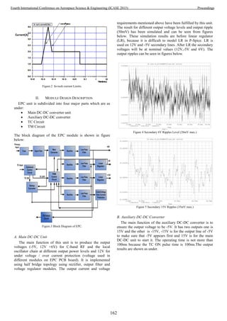

![describe the design and analyze results of EPC module for
new generation communication satellite payload receivers for
a given set of specific space qualified requirements. The
output voltage ripples have been minimized to 25mV is
presented. The input/output voltages, in-rush current
protection, TM and TC characteristics, bus voltage ripples and
other requirements which make its design complex and
significant for RF point of view. Both the output current and
voltage requirements are presented and met successfully. The
design presented is also compliant with the TC requirements.
The under voltage and over current protections are also
implemented to protect satellite in case of short circuits or
lower main bus voltage. All the four major modules of EPC
(main DC-DC converter unit, auxiliary DC-DC converter, TC
circuit and TM circuit) are discussed and analyzed along with
their simulated results.
REFERENCES
[1] Ioana-Monica, Pop-Calimanu, Prutianu Florin, and Popescu Viorel.
"Design and simulation of DC/DC boost converter used for distributed
sensing system based on a multidrop sensor network with RS485
interface", 2012 10th International Symposium on Electronics and
Telecommunications, 2012.
[2] Pequet, E.; Delporte, P.; Fayt, P.; Gak, M.; Canon, T., "ESA qualified
EPC for telecommunication satellites TWTA," Vacuum Electronics
Conference, 2000. Abstracts. International , vol., no., pp.2 pp.,, 2-4 May
2000.
[3] R. E. Sorace, V. S. Reinhardt, and S. A. Vaughn, “High-speed digital-to-
RF converter,” U.S. Patent 5 668 842, Sept. 16, 1997.
[4] Castiaux, J.P.; Bury, P.; Liegeois, B., "Power conditioning units for high
power geostationary satellites," Power Electronics Specialists
Conference, 1997. PESC '97 Record., 28th Annual IEEE, vol.1, no.,
pp.722,733 vol.1, 22-27 Jun 1997.
[5] http://www.space-airbusds.com
[6] https://www.thalesgroup.com
[7] http://www.sstl.co.uk
[8] Garrigos, A.; Carrasco, J.A.; Blanes, J.M.; Sanchis-Kilders, E., "A
power conditioning unit for high power GEO satellites based on the
sequential switching shunt series regulator," Electrotechnical
Conference, 2006. MELECON 2006. IEEE Mediterranean , vol., no.,
pp.1186,1189, 16-19 May 2006.
164
Fourth International Conference on Aerospace Science & Engineering (ICASE 2015) Proceedings](https://image.slidesharecdn.com/conferenceproceedingsicase2015final1-160918062150/85/Conference-proceedings-173-320.jpg)
![DSP Based Electro-Hydraulic Actuator Control
with Irretraceable Feedback Error
Compensation
Najam-Ud-Din Ahmed, Syed Aleem Azhar, Khadim Hussain
Abstract—This paper describes the interfacing detail of
Electro-Hydraulic actuator with DSP and addresses the
issues which commonly occur during development. The
purpose of designing digital controller on DSP is it’s
easy configurability via software and requirement of
less analog part. Scenarios where a dc-dc converter
used as voltage source may induce erroneous feedback
in the feedback control system due to its dual output
mismatch. And despite a good PID controller real
position of manipulator may have errors which are
irretraceable even by the intelligent controller schemes.
A judicious and intelligent use of available DSP
peripherals like ADCs, DACs etc and minor adjustment
of circuit can effectively increase the real time accuracy
of whole system against irretraceable errors.
Keywords—DSP based PID, PID Controller,
Irretraceable error, Erroneous feedback compensation
I. INTRODUCTION
It is common practice to use DSP or any digital
controller to control analog manipulators and
actuators in mechatronic applications [3]. However,
noise and supply voltage accuracy dependability of
analog systems is always associated with them and
affect the accuracy of the overall system. There are
many advanced as well as conventional control
schemes to increase the performance of the actuator
[2] but these schemes might be less affective if the
feedback is erroneous or we have high tolerances in
the supply voltages. This paper discusses such a
scenario where a dc-dc converter used as voltage
source may induce errors in the feedback system due
to its dual output mismatch. And despite a good
controller real position of manipulator may have
errors which are irretraceable by the intelligent
controller schemes. In addition, use of digital
controller specially a DSP helps in generation of real
time rate for interfacing. Although various techniques
are available for getting precise band-gap reference
voltage [1] but DSP based controller also adds noise
immunity which is always associated with analog
systems.
II. PROBLEM STATEMENT
Two hydraulic pistons are used in a robotic arm
for high speed application prototype. Feedback is
based on linear potentiometer for which dual supply is
required. It is known that 1% error in supply voltage
will produce same error in the feedback which will be
not traceable in potentiometer based feedbacks and
still be added in the real position of actuator.
Output Voltage (Vout) at potentiometer viper is,
(1)
(2)
(3)
(4)
(5)
( )
(6)
This error may be induced due to two factors
1. Due to tolerance in supply
2. Due to mismatch in dual supply
There is always a pinch of tolerance in supply and
it is always expensive to use high grade supply unit or
165
Fourth International Conference on Aerospace Science & Engineering (ICASE 2015) Proceedings](https://image.slidesharecdn.com/conferenceproceedingsicase2015final1-160918062150/85/Conference-proceedings-174-320.jpg)

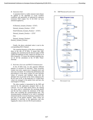
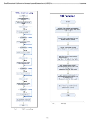

![circuit but also the errors associated with use of
additional components in any circuit.
REFERENCES:
[1] LinHaiCui. Design of a High Precision Band-gap
Voltage Reference. Proceedings of the 2011
International Conference on Electronic & Mechanical
Engineering and Information Technology. IEEE, 2011 :
2187~2190.
[2] Sergey Edward Lyshevski and Trevor C Smith.
Tracking Control of Direct-Drive Servos. Proceeding of
the 2011 International Conference on Decision and
Control and European Control Conference(CDC-
ECC).Orlando, FL, USA, IEEE, 2011 : 1602~1607.
[3]Hai-tao Wang, Ze-Zhang and Xiang-yu Liu. Design of
Control System for Brushless DC Motor based on
TMS320F28335.Proceeding of the 2011 Third
International Conference on Measuring Technology and
Mechatronics Automation. IEEE, 2011 : 954~958.
[4]D-module D-sign T manual.
[5]VisualDSP++ 4.0 - C/C++ Compiler and Library
Manual for SHARC Processors.
[6]ADSP-21065L SHARC DSP - User's Manual and
Technical Reference
170
Fourth International Conference on Aerospace Science & Engineering (ICASE 2015) Proceedings](https://image.slidesharecdn.com/conferenceproceedingsicase2015final1-160918062150/85/Conference-proceedings-179-320.jpg)
![Design for Test Approach using FPGA for BPSK
Modem
Syed Jahanzeb Hussain Pirzada1
, Muhammad Faisal Arain1
, Rahman Mehboob1
1
Space and Upper Atmosphere Research Commission (SUPARCO), Pakistan.
Abstract— Implementation of modem has always been the key
interest for researchers working in the field of communication.
Nowadays, at low frequencies (in kilohertz range) the modulation
and demodulation is performed digitally. As, modem is utilized
for telemetry and telecommand communication between satellite
and ground station. This work provides the design of test bed for
modem. The testing is performed using ECSS based Standards.
This paper explains the design of test bed for testability of Binary
Phase Shift Keying modem implemented on Field Programmable
Gate Arrays. The testing of FPGA based modulator was
performed using signal analyzer. On the other hand the testing of
FPGA based demodulator was complicated and needs to be
design on seperate hardware; as it contains carrier recovery, bit
syncronization and bit recovery. Hence, digital signal processor
and FPGA based co-processing test bed was design and
developed for tesing of demodulator. The experimental results
show the architecture and testing results of the proposed
approach. The proposed methodology describes the problems
encountered during testing and proposed solutions to it. Such as
in demodulation, the bit recovered from demodulation can be
analyzed on oscilloscope but it is cumbersome. Therefore, an
asynchronous bit recovery algorithm is employed with serial
communication for representation and verification.
Keywords- DSP, BPSK, modulator , demodulator.
I. INTRODUCTION
Digital modulation is utilized to convert digital symbols into
waveforms to make it compatible with the characteristics of
transmission channel [3]. In digital modulation, a baseband
signal is changed into band pass signal compatible for
transmission. Similarly, demodulation is utilized in receiving
end to recognize the detected data.
Binary Phase Shift Keying (BPSK) is employed in
transmission and reception of telemetry and telecommand
data in satellites. It is the simplest form of phase shift keying
(PSK). Specially, at low frequencies (in kilohertz range) the
modulation and demodulation is performed digitally.
Generally it consists of two phases one is inphase with the
transmitted carrier and other is out of phase with the
transmitted carrier as represented in Figure 1. The two
conditions are generally represented as logic 0 and logic 1, the
formula associated with it represented in eq-1 and eq-2 [4].
Figure 1: Phase change of BPSK signal.
A Test bed is essential for rigorous testing of the system.
Implementation of digital modulation schemes have become
more and more attractive and simple with the used of digital
signal processors (DSP) and Field Programmable Gate Arrays
(FPGA). Recently, researcher are utilizing the processing
power of FPGA and DSP together to implement systems.
Testing of BPSK modem is very important as all the data
transmitted through the transmission channel depends on the
correctness of implmentation of baseband modualtion.
The remaining paper is organized as follow. Section II
provides the previous work. Section III explains the proposed
methodology. Section IV explains experimental results.
Section V provides conclution of this paper.
II. PREVIOUS WORK
Many researchers have designed and developed BPSK
modulator and demodulator in the Past [2] [5] [7] [8]. The
testing with genralized equipments are usually quoted in many
implementation. Including some results are acquired in the
form of software simulations. In this paper a testbed based
testing mechanism is proposed. Although it is formed using
traditional testing equipment but incombination with custom
solution.
III. PROPOSED METHODOLOGY
Testing of BPSK modem is proposed in this paper. The test
setup is composed of two sets of modems. One is the designed
BPSK modem to be utilized in telemetry and telecommand
module and other is for testing of designed BPSK modem.
For testing of BPSK modulator and demodulator designed on
FPGA to be utilized for telemetry and telecommand. A testing
171
Fourth International Conference on Aerospace Science & Engineering (ICASE 2015) Proceedings](https://image.slidesharecdn.com/conferenceproceedingsicase2015final1-160918062150/85/Conference-proceedings-180-320.jpg)
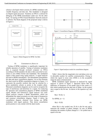
![TABLE I
PERFORMANCE CHARACTERISTICS OF BPSK MODULATOR
S.No Modulation Accuracy
Category Results Peak Unit
1 EVM 0.662 1.665 %
2 Magnitude Error 0.561 1.661 %
3 Phase Error 0.20 0.82 %
4 Amplitude Drop 0.01 - dB
5 Origin Offset -73.86 - dB
6 Gain Imbalance 0.00 - dB
7 Quadrature Error 0.00 - deg
8 SNR (MER) 43.58 - dB
9 RHO 0.999 - -
Figure 5: Spectrum representation of BPSK modulator on signal
analyzer.
Testing of demodulator is performed with DSP based BPSK
modulator and FPGA based debugging equipment. Result of
simulation on Code Composer Studios (Software used for
programming TI DSP Kits) are shown in Figure 6, Upper half
of the figure shows input converted to NRZ signal and in the
lower half corresponds to modulated BPSK signal [1]. The
BPSK modulator implemented on Texas Instruments
TMS320C6713 DSP kit has variable frequency and data rate
configurations. Althought in this testing application data rate
and frequency is fixed. The data from BPSK modulator is
provided through test computer serially and it modulates the
data. The modulated data is then input to FPGA based BPSK
demodulator. After the demodulation the data is transfered to
FPGA based Debugger for viewing the retreived output.
V. PROBLEMS AND SOLUTIONS DURING TESTING
Several problems are encountered during the testing of BPSK
modem implemented on FPGA. Firstly, The bit recovered
after demodulation are continous, in long data stream it will be
difficult to monitor it in osciloscope. Therefore, a uart based
debug ging is implemented on FPGA for validation of
demodulator performance. Secondly, Analog to digital
converter has been tested seperately but on integration with
FPGA and DSP based modualator the rescaling was required.
Lastly, there was a transmission rate missmatch between ADC
and uart transmission. So the data from ADC is stored in
memory and then transmitted through uart transmission.
Figure 6: CCS Graph results of NRZ converted data and BPSK
modulated signal.
VI. CONCLUSION
Our experiment showed testbed setup for BPSK modem.
Test setup for testing of BPSK modem using signal analyzer
and DSP/ FPGA test setup was proposed. The problems
encountered are discussed.
ACKNOWLEDGMENT
This work was supported by Space and Upper Atmosphere
Research Commission (SUPARCO). Authors also
acknowledge the efforts of Mr. Muhammad Faisal and Mr.
Razi Iqbal for continuous support and efforts for completion
of this research work.
REFERENCES
[1] G.Susinderrajan, S.Saran Kumar, T.Shankar, K.Sreeram,
P.V.Ramakrishna, "Design of a Low Cost All-Digital PSK/PM Satellite
Telemetry Transceiver", IEEE Electron Device Letters, vol. 20, 569–
571, Nov. 1999.
[2] S. Ruque, I. Ruiz, E. Carrión, "Simulation and implementation of the
BPSK modulation on a FPGA Xilinx Spartan 3 xcs200-4ftp256, using
Simulink and the System Generator blockset for DSP/FPGA", IEEE
Electron Device Letters, vol. 20,569–571, Nov. 1999.
[3] B.Sklar, “DigitalCommunications Fundamentals and Applications”, 2nd
ed. Englewood Cliffs, NJ: Prentice-Hall PTR, 2001.
[4] S. Johanna, Ruque, D.Ruiz, Carlos, “Simulation and implementation of
BPSK system on a FPGA board using system generator blockset for
DSP/FPGA”, School of Electronics and Communication, Technical
university Loja 2005.
[5] C.J. Harsha, D.H. Sandeep, A.S. Mali,"Hardware Implementation of
BPSK system on Virtex2-Pro FPGA using Xilinx System
Generatror".International Refereed Journal of Engineering and Science
(IRJES), vol. 2, pp 18-24, January 2013.
173
Fourth International Conference on Aerospace Science & Engineering (ICASE 2015) Proceedings](https://image.slidesharecdn.com/conferenceproceedingsicase2015final1-160918062150/85/Conference-proceedings-182-320.jpg)
![[6] J.G. Proakis, Digital Communication, 5th edition, McGraw Hill New
York, 2001.
[7] H. Malik, D.R. Rotake, M. Mahajan,"Design and Implementation of
BPSK Modulator and Demodulator using Vhdl". IOSR Journal of
Electronics and communication Engineering (IOSR-JECE), Vol. 9, pp
98-105, May-Jun 2014.
[8] N. P. Shrirao, A.P. Thakare,"Design of Digital Modulators:BASK,
BPSK and BFSK using VHDL". International Journal of Advanced
Research in Computer Science and Software Engineering (IJARCSSE),
Vol.3 january 2013.
174
Fourth International Conference on Aerospace Science & Engineering (ICASE 2015) Proceedings](https://image.slidesharecdn.com/conferenceproceedingsicase2015final1-160918062150/85/Conference-proceedings-183-320.jpg)
![Design of a Fuzzy Logic Water Level
Controller
Taimoor Zahid
Institute of Space Technology,
Islamabad, Pakistan
taimoor187@yahoo.com
Nosheen Zafar
COMSATS Institute of Information Technology,
Islamabad, Pakistan
nosh_zaf@hotmail.com
Abstract— This paper analyzes the effectiveness of
water level control using the concepts of Fuzzy Logic.
We have designed a Fuzzy Logic Controller for Water
Tank Level Control by using the linear control valve,
the level transmitter and the fuzzy control rules built in
the Fuzzy Logic Tool-Box and Simulink in MATLAB
and have then compared the control effect with that of a
Proportional–integral–derivative (PID). This design can
be very valuable for the industries where water level
control is extensively used and a slight deviation can
lead to major accidents and huge losses in revenue.
Therefore, it has become necessary to develop an
accurate and cost effective control system. The purpose
of such controller is to sustain a set point at a particular
value and be able to dynamically accept the new values.
Sometimes steady-state error and overshoot can no
longer be taken into account by the PID Controller due
to increase in the complexity, hysteresis, nonlinearity
and coupling of control object. While on the other hand,
with the development of the Intelligent Control Theory,
the application of Fuzzy Controller has become very
popular in practical industrial automation applications
and these problems can be successfully dealt with using
Fuzzy Control.
Keywords— Water Level Control, Fuzzy Logic, PID,
Tank, Mamdani.
I. INTRODUCTION
During the past several years, Fuzzy Control has
emerged as one of the most active and fruitful areas
of research in the application of Fuzzy Set Theory
[1]. Due to its robust, precise and orderly approach
for operating the controller, Fuzzy Logic can be used
in several applications. The field of Control System
Engineering has benefited the most from the success
of Fuzzy Set Theory. The reason behind this
unexpected success is high performance rate and low
cost. Although PID-Controllers are easy to install but
their performance can deteriorate quite fast when
used in non-linear systems [2]. Moreover, the
selection of the parameters of PID is also a difficult
task. If one does not choose the fine parameters, it
will badly impact the working of controller. Fuzzy
Control gives more attention to various parameters,
such as the time of response, the error of steadying
and overshoots [3].
This paper shows the development and
implementation of Fuzzy Logic Controller for Flow
Control Application because Fuzzy Controller can
achieve greater control results where limit of
overshoot is strict [4]. We have taken the level of the
water tank as an object and designed a Fuzzy
Controller in MATLAB. The Simulink models are
generated to see the working of tank. The controllers
are then added in those models to check and
understand the working of the designed controllers.
The control effect is examined and compared with
the effect of PID Controller. After designing the PID
and Fuzzy Controllers, the results are compared. This
approach of simulation by MATLAB allows us to
solve more complicated problems and develop the
measuring states to improve modeling and analysis of
system and to allow more control in the designs [5].
The overall goal of this paper is to show which
controller is better for flow and control applications.
II. THE TANK PROCESS
Input, Process, Feedback and Output are the four
steps of tank process.
1) Input: A square-shaped waveform of
amplitude 0.5 and frequency 0.1 Hz is
generated from the signal generator as given
by (1).
y(t) = Amp * waveform(freq, t) (1)
2) Process: The Tank-Process includes valve,
tank and controller. The water is pumped
into the tank via valve with controllable
degree of opening. Water flows out of the
tank through a hole in the bottom with area
0.05 m2
. The height of the tank is 2m, and
the cross-sectional area of the tank is 1m2
.
175
Fourth International Conference on Aerospace Science & Engineering (ICASE 2015) Proceedings](https://image.slidesharecdn.com/conferenceproceedingsicase2015final1-160918062150/85/Conference-proceedings-184-320.jpg)
![Technically, the water level in the tank can
be described mathematically using (2).
= √ – (2)
Where h is the water level [m], is the influent
flow rate [m3
/h] and and are parameters
depending on the tank and outflow areas. The
influent flow rate depends on the degree of valve
opening. In simulations, the water level in the tank is
controlled towards some pre-specified value
(reference signal) by letting the controller manipulate
the degree of valve opening. Eq. (2) will be used in
designing the Simulink model for controlling the
water level for the designed tank.
Figure.1 Water Tank System
3) Feedback: The signal is generated from the
signal generator and is further processed
through controller. This output from the
process becomes a feedback. This feedback
goes to a summer named error. It is named
so because it calculates the difference
between actual and desired water level. The
actual value is the one which is coming
through feedback and the desired is the one
which is coming straight through the signal
generator.
4) Output: The output can be generated via:
(a) To workspace: It writes the input to the
specified array or structure in MATLAB’s
main workspace. The “To Workspace”
block takes the signal as input and writes the
data of the signal into the workspace of
MATLAB. Data is not available until the
simulation is paused or stopped. This block
writes the data to an internal buffer during
the simulation and that data is written to the
workspace when a simulation is completed
or paused.
(b) Comparison: This block generates a plot and
that plot gives the comparison between the
reference signal and system output.
(c) S-function: This block provides a direct
access to the additional parameters to be
passed to S-function. The functions
parameters can be stated as variables
separated by commas or as MATLAB
expression. This function displays the
number of I/O ports plus the names of
specific S-functions. In our case, the built-in
file named “tankdemo” is used for
generating the animation. The S-function
used in this application refers to the
“animtank” which is built-in in the
MATLAB directory. ANIMTANK stands
for “Animation of water tank system”.
III. PID-CONTROL OF TANK WATER
LEVEL
A. PID Controller
PID controller refers to a Proportional–integral–
derivative controller. In order to overcome the
shortcoming of self-tuning PID controllers, fuzzy
logic and neural networks are utilized [2]. The
conventional PID is commonly utilized in controlling
the level, but the parameter of those controllers must
be turned by tuning method either in time response or
frequency response to meet their required
performances [6, 7]. The block diagram of PID
Controller with constants is shown in Figure. 2. P
element: e (t) is the proportional to the error at the
instant t, which is the present error. I element:
∫ dt is proportional to the integral of the error
up to the instant t, which can be interpreted as the
accumulation as the past error. D element: is
proportional to the derivative of the error at the
instant t, which can be interpreted as the prediction of
the future error. [8]
Figure.2 Block diagram of PID Controller
176
Fourth International Conference on Aerospace Science & Engineering (ICASE 2015) Proceedings](https://image.slidesharecdn.com/conferenceproceedingsicase2015final1-160918062150/85/Conference-proceedings-185-320.jpg)
![B. Simulink Model of Water Level Controller
Considering the tank process described above, the
Simulink Model is designed the as shown in the
Figure.4 and is saved with the name of
“tankpid.mdl.” Figure.4 illustrates that the process
includes PID Controller, valve and water tank.
1) Controller: The PID controller is the built-in
block in the Simulink. Its block diagram
representation is shown in the Figure.3. As
described earlier, it has three parts namely
proportional, integral and derivative. The input
is an error signal (difference between the
reference signal and system output) which when
comes into the controller is divided into three
respective parts and output from each of these
parts is then summed up to give a stable output.
The output of this block is the weighted sum of
the input signal, the integral of the input signal
and the derivative of the input signal [9]. In this
case, this controller is acting as a PD-controller
as the parameter which set for the integrator is
zero.
Figure.3 Block Diagram for PID-Controller
2) Valve: The water is pumped into the tank via
valve with controllable degree of opening. 0
means the valve is closed and 1 means that the
valve is fully open. The more the valve is open
(the closer the value is to one), the larger the
inflow to the tank. As illustrated in Figure. 5,
the product of the condition provided in the
limited integrator and inflow rate of the water
gives the rate at which water flows out. One of
the important parts of the valve is limited
integrator. The reason behind using the limited
integrator is to stop the output from surpassing
specific levels. The function of this block is
that, as soon as the output surpasses the limits,
it turns off the integral action for preventing the
integral wind up. The limits can be changed for
the period of simulation.
Figure.5 Simulink Model for Valve
Figure.4 Simulink Model for PID- Controller
3) Tank: The water level in the tank can be
described mathematically using (2) and tank
thus designed is shown Figure 6.
177
Fourth International Conference on Aerospace Science & Engineering (ICASE 2015) Proceedings](https://image.slidesharecdn.com/conferenceproceedingsicase2015final1-160918062150/85/Conference-proceedings-186-320.jpg)

![The input range is [-1, 1]. It consists of three
membership functions namely high, good
and low. Trimf is used for ‘good’, and
Trapmf for ‘high’ and ‘low’ as a nominal
function. These membership functions are
shown in Figure.9.
Figure.9 Membership function for input variable ‘level’
(b) Input 2: The rate (flow rate) is defined as the
second input. Its range is [-1, 1]. The
membership functions are named as ‘rising’
and ‘falling’. Trapmf is used as a nominal
function.
Figure.10 Membership function input variable ‘rate’
(c) Output: The designed system has only one output
given by the linguistic variable ‘valve’. It basically
represents the position of the valve by accounting for
the change in valve opening. The output space range
is [-1 1]. The membership function for the output is
shown in Figure.11.
Figure.11 Membership function for output variable ‘valve’
2) Rule Base: The input-output relationships
are used to develop the IF-THEN rules for
the FIS [10]. From the two input variables
and one output variable total of four
following rules are developed.
1. If (level is low) then (valve is open_fast)
2. If (level is high) then (valve is close_fast)
Figure.12 Simulink Model of Fuzzy Controller of Water Tank
3. If (level is good) and (rate is rising) then (valve is
close_slow)
4. If (level is good) and (rate is falling) then (valve is
open_slow)
B. Design of the Simulink Model
179
Fourth International Conference on Aerospace Science & Engineering (ICASE 2015) Proceedings](https://image.slidesharecdn.com/conferenceproceedingsicase2015final1-160918062150/85/Conference-proceedings-188-320.jpg)
![After setting the parameters of the FIS membership
function and making the fuzzy controller; the FIS file
named “tank.fis” is exported to the workspace. The
reason behind the fact that the derivative of the
process variable is taken instead of the derivative of
error is that the derivative mode amplifies the sudden
changes in controller input signal and cause large
variation in the controller output. [11]. Now the tank
with Fuzzy Controller can be simulated by using
model shown in Figure.12 and the output comes out
to be as shown in Figure.13.
Figure.13 Output of Fuzzy Controller
V. CONCLUSION
In plant process control, the measurement and control
of flow are two very important factors. But these two
factors are susceptible to disturbances because of the
different variables affecting the flow rate. Therefore
for optimizing the performance of a plant, the flow
controllers are required to be robust. Fuzzy Logic
Controller is proposed to replace the conventional
PID controller due to its superior applicability and
robustness [12]. The concept of Fuzzy Logic is a
representation of the human thinking and decision
making process. The experimental results show that
Fuzzy Control is better than PID Control not only
because of simplicity of its implementation, better
control performance, robustness and overall stability
but also because it gives a reasonable consideration
to variety of parameters like overshoot and time of
response etc and for this reason, it tunes and develops
the FIS more intuitively as compared to the PID
Controller.
REFERENCES
[1] L.A. Zadeh, “Fuzzy Sets”, Informal Control, Vol. 8, Pp. 338-
353, 1965.
[2] Y. F. Chan, W. Chan and H. T. Mok "Adaptive Neurofuzzy
Network Based PI Controllers with Multi-objective
Functions",Next-Generation Applied Intelligence, Vol. 5579, Pp.
604-613, 2009.
[3] Qi Li, Yanjun Fang, Jizhong Song, Ji Wang, "The Application
of Fuzzy Control in Liquid Level System", 2010 International
Conference on Measuring Technology and Mechatronics
Automation, 03/2010.
[4] Wangnipparnto S. and Tunyasrirut S., "Level Control in
Horizontal Tank by Fuzzy Logic Controller", 2006 SICE-ICASE
International Joint Conference, 10/2006.
[5] Duane Hanselman and Bruce Littlefield, "Book: Mastering
Matlab® 5", ISBN# 0-13-858366-8, Prentice-Hall, 1998.
[6] W. K. Ho, C.C. Hang, and J. H .Zhou, "Performance And Gain
And Phase Margins Of Well-Known Pituning Formulas,"
Accepted For Publication In IEEE Trans. Contr. Syst. Techno,
1995.
[7] J. G .Ziegler and N. B. Nichols, "Optimum Settings for
Automatic Controller," By ASME Trans. Vol. 64, Pp.759-768,
1942.
[8] Aravind, Sekhar R, and B R Vinod, "A generalized method for
improving the performance of controllers by combining PID and
DELTA rule", 2012 Annual IEEE India Conference (INDICON),
2012.
[9] “MATLAB documentation,” Mathworks
(www.mathworks.com )
[10] Pathmanathan E, and R Ibrahim., "Development and
implementation of Fuzzy Logic Controller for Flow Control
Application", 2010 International Conference on Intelligent and
Advanced Systems (ICIAS), 2010.
[11] Silviu Ionita and Emil Sofron, “The Fuzzy Model for Aircraft
Landing Control”, Prentice Hall, 2001
[12] Ronald R. Yager and Dimitar P. Filev, “Essentials Of Fuzzy
Modeling And Control”, Johan Wiley & Sons, 2002.
[13] D. Wu, F. Karray, I. Song, ‘Water level control by Fuzzy
Logic and Neural Networks’, IEEE Conference on Control
Applications, pp.3134-39, 2005.
[14] Namrata Dey, Ria Mandal and M. Monica Subashini, “Design
and Implementation of a Water Level Controller using Fuzzy
Logic”, International Journal of Engineering and Technology
(IJET), Jun-Jul 2013.
[15] J. Yen, "Fuzzy logic-a modern perspective", IEEE
Transactions on Knowledge and Data Engineering, 1999
180
Fourth International Conference on Aerospace Science & Engineering (ICASE 2015) Proceedings](https://image.slidesharecdn.com/conferenceproceedingsicase2015final1-160918062150/85/Conference-proceedings-189-320.jpg)

![Nuclear reactors have provided electrical power for
some of the U.S. space program’s greatest successes,
including the Apollo lunar landings and the Viking
Landers that searched for life on Mars. RTGs made
possible NASA’s celebrated Voyager explorations of
Jupiter, Saturn, Uranus and Neptune, RTG Power
sources are enabling the Galileo mission to Jupiter, the
international Ulysses mission studying the Sun’s Polar
Regions, and the Cassini mission to Saturn.
Pioneer 10 was launched from Cape Kennedy on 2
March 1972. It was the first interplanetary probe,
successfully navigating the asteroid belt before
Making rendezvous with Jupiter and Saturn The probe
was equipped with an array of instruments for
measuring such phenomena as the solar wind and the
magnetic and radiation fields surrounding Jupiter.
Nuclear reactors being a reliable and competitive source
of energy they have some risk too and as well it also
becomes difficult to do in some condition. The
overcome of these problems are also demonstrated in
this paper.
II. Space power concept:
To remove the waste, to lift a load and as well as for
communication in International space station or on
ground you will need sufficient power to do so for a
long time. Moreover it would be very difficult for to
generate electricity by thermal or chemical means in
microgravity environment [5].
However with the availability of radioactive isotopes
and as well as with the help of nuclear reactors the
Electricity and all the other requirements in ISS would
be easily available without any difficulty for several
years [5]
For the production of electricity heat energy can be
converted by many devices but the precise one is to use
Thermo electric generator which typically works on
Seebak Concept i.e
dV = SAB
.
(Kh - Kc)
Where
dV is Voltage difference, SAB is two dissimilar
metals, & Kh - Kc is temperature gradient.
In this way Nuclear reactors can provide infinite power
for almost any time. However, they are not practicable
for applications below 15 kilo watt (kW).
Figure 1 : regimes of possible space power applicability
182
Fourth International Conference on Aerospace Science & Engineering (ICASE 2015) Proceedings](https://image.slidesharecdn.com/conferenceproceedingsicase2015final1-160918062150/85/Conference-proceedings-191-320.jpg)
![Radioisotopes are considered to be best used for
continuous supply of low levels (up to 5 kW) of power
or in combinations up to many times this value. For this
reason, especially for long interplanetary missions, the
use of radioisotopes for communications and the
powering of experiments are preferred. The nuclear
process shown in Fig. 2 can either be a critical reactor or
radioisotope fuel source such as plutonium oxide. In
either case the heat can be converted to electricity either
statically through thermoelectric or a thermionic
converter, or dynamically using a turbine generator in
one of several heat cycles (Rankin, Stirling, Brayton)..
The nuclear workhorses for current space missions are
the RTGs and the TEGs powered by radioisotopes in the
Russian Federation that provide electricity through static
(and therefore reliable) conversion at power levels of up
to half a kilowatt, or more by combining modules. And
that energy can be used for to run machinery. [2].
Space Propulsion concept
Nuclear reactor can also be used in rocket propulsion
system. Propulsion system in space is to change the
position Or velocity (v), of space craft under the strong
influence of gravity. [6]
When a space craft moves it generally term is
momentum (mv) so, the basic concept of propulsion is to
change the momentum (mv) of a space craft, and change
in momentum is known as impulse (Imp). So, the basic
aim of propulsion in space is to create impulse, to
measure the impulse is often term is specific impulse
(Isp).[6]
Specific impulse also known the exhaust velocity (ve)
(OR) the impulse per unit weight ( ) but while
discussing the engine in space there is no weight so it
can become impulse per unit mass
The difference arises here only by the acceleration due
to gravity (g).Where its value is 2
on earth.
However the value of g and reaction mass is not
important while the vehicle discussing in space. [4].
The two parameter specific impulse and the mass of the
rocket during launch and then in orbit is measure the
efficiency of propulsion energy.
Where the equation for the measure of specific impulse
as seen as (1)
(1)
Where represent mass of propellant and
represent mass flow.
Here it is seen that mass of propellant is inversely
proportional to specific impulse, So, In chemical
propulsion there is used hydrogen and oxygen which
provides a specific impulse about 4400 m/s with mass
ratio of earth escape of 15.[1]
Figure 2.The conversion of heat energy into kinetic or to
mechanical energy
183
Fourth International Conference on Aerospace Science & Engineering (ICASE 2015) Proceedings](https://image.slidesharecdn.com/conferenceproceedingsicase2015final1-160918062150/85/Conference-proceedings-192-320.jpg)
![However americium OR hydrogen heated with fission
reactor can achieves twice the impulse with mass ratio
of 3.2. And with different core it can be generate much
more impulse i.e. seven times having mass ratio of only
1.2 [1].
III. Nuclear rocket
Nuclear rocket is the rocket which use nuclear reactors
usually fission concept instead of chemical propulsion to
generate thrust it include nuclear thermal rocket (NTR),
Nuclear electric rocket (NER) or Hybrid (NTR/NER).
[2]
These rocket are propelled by the force of nuclear
explosion, usually liquid hydrogen is heated via nuclear
fission which subsequently can be expanded in nozzle
and thus accelerated at a high ejection velocity (6,000 to
10,000 m/s) to generate thrust. There are also many
design are find for nuclear thermal propulsion i.e. liquid,
solid or gas core rocket. [6]
They use solid, liquid or gas core reactors respectively.
Electro thermal propulsion rocket have been use in
many orbital mission in this type of rocket the propellant
is heated electrically (heat energy of nuclear reactor are
converted into electricity) and then it accelerate the
ionized gas via electrostatic force at supersonic velocity
having range from 1,000 to 5,000 m/s and thrust range
0.01 to 0.5 N. But it has low Specific impulse therefore
it can be use only for interplanetary missions, however,
it can be use for long time instead of chemical rocket [2]
The nuclear rocket has many advantages which
overcome on chemical rocket. Like it can be use in
much complicated mission even it can be travels to the
edge of our solar system or even to our nearest cluster,
nuclear space craft can be also used for to carry heavy
payload or to carry flyby, rover etc to the far planet in
our solar system, because it provides a large specific
impulse as a result faster travel and the probability for
complicated missions can be met, secondly nuclear
reactor has low molecular weight which can increase the
propulsive force per unit of propellant flow and allowing
us for increase the proportion of total weight of payload
[3].
IV. Microgravity effect on core
reactor
In microgravity environment every mass tends to be in
state of motion (try to revolve from heavenly bodies
near them due to centripetal force) So, The big challenge
of core reactors in microgravity environment is to
control the flow of fission. It seems like very difficult
but under certain design it is possible to keep the
reaction self sustain. So the level of energy would be
maintained. In core reactors usually the flow is
turbulent due to the randomness motion of molecule.
And hence it becomes difficult to keep flow within
specified boundaries. For this reason Reynolds number
flow are preferred for microgravity environment.
If it is not under the specified boundaries then the chain
reaction times would be increases due to uncontrolled
condition in the core reactor. And some parts of the core
reactor are exposed and hot spot would be appear on that
as well some parts of the core reactors would be damage
due to high temperature because the distribution of heat
is not possible in such circumstance.
184
Fourth International Conference on Aerospace Science & Engineering (ICASE 2015) Proceedings](https://image.slidesharecdn.com/conferenceproceedingsicase2015final1-160918062150/85/Conference-proceedings-193-320.jpg)
![Figure 3 Precise core reactors for microgravity environment
1, Reflector moderator 2, Gaseous fissile zone 3,
Working medium flow zone, 4, Fissile material
diminution replenishment 5, working medium Inlet.
To overcome on this problem a special core is design
(shown in figure 3) to sustain fission reactor under
control especially with this core the possibility of
environmental hazard would be reduce. And various
high temperature fuels are possible with this design. in
The fissile material for example Uranium or americium
would be located in the center of cavity enclosed by the
neutron moderator reflector. The working gas flow is
close to the cavity walls and it is heated by the high
temperature plasma radiation which causes the fission
reaction to be self sustained under microgravity
conditions. [8]
V. Radiation hazards of Nuclear
rocket
Expose of a person to radiation does not mean that the
person would get cancer. People are exposing to
radiation on daily basis like on lesser extent from human
activities i.e.-rays. And radiation comes out from natural
environment i.e. in the earth cosmic rays and radon. The
radiation expose is measures in unit of Dose called
millirem. Over the course of year the average person
would expose to a total of 360 millirem to natural
radiation .In nuclear thermal rocket some of the
radioactive element would be release into the
atmosphere The particles which are hazardous to people
would remain high in the atmosphere for long course of
time gradually these particles being spread thinly across
the world. And eventually making their way on the
surface especially on ocean since these materials are
Insoluble once it reaches to the surface most of it would
become trapped by the soil or by the ocean and not pose
a health hazard. Thus most of the release materials
won’t be breath by people. But the small amount of
released material would be breath by the people and as
well this small amount will be also distributed across the
world. So, In this way the amount to be breath will be
much less the person may receive it less than one
millirem in 50 years. This small radiation is negligible
compare to the 15,000 millirem a person will get it from
natural resources over the period of 50 years. [7]
VI. Result and conclusion
In this paper we have emphasize on the importance of
nuclear reactors in space based application, where the
nuclear reactors and radioactive isotopes would provides
infinite heat energy for long durations during journey of
the space craft and that energy can be converted into
other form of energy and the need for power and
propulsion would be met. But in microgravity
environment it becomes difficult to do but however with
the help of gas core reactors and other special core
design would allow us to do so in microgravity
environment too. And the space exploration would be
become more precious and peaceful.
185
Fourth International Conference on Aerospace Science & Engineering (ICASE 2015) Proceedings](https://image.slidesharecdn.com/conferenceproceedingsicase2015final1-160918062150/85/Conference-proceedings-194-320.jpg)
![VII. Acknowledgment
I would like to thank national space agency SUPARCO
Space awareness society including Mr. Qamar Abbas
and Mr. Tahir hussain and My School principal Mr.
Sami ullah for to guide me as well for their support. I
also like to express my gratitude with SUPARCO
propulsion team for did my conceptual analysis.
I am also grateful to Mr. Rahman u din and Mr. Zulfiqar
Ali for Insatiable support and guide.
References
[1]. Rocket propulsion elements: introduction to
the engineering of rockets by George P. Sutton,
Oscar biblarz___7th
edition.
[2].The role of nuclear power and nuclear
propulsion in peaceful exploration of space by
International atomic energy agency Austria
September 2005.
[3]. Basic of space flight by National Aeronautic
and space administration sec 2, 2002.
[4]. Advance space propulsion for the 21st
Century
by Robert H .Frisbi a report from 9 August 2003 to
15 September 2003[5].Civilian usage of nuclear
reactors in space volume 1, science and global
security, 1989,
[6] Thruster precisely guide by Hiss, M martin and
K, Rachule October 2002.
[7] Space craft power for cassini
(http://www.jpl.nasa.gov/cassini/)
[8] Fission fragments heating for space propulsion
by C. Rubbia
186
Fourth International Conference on Aerospace Science & Engineering (ICASE 2015) Proceedings](https://image.slidesharecdn.com/conferenceproceedingsicase2015final1-160918062150/85/Conference-proceedings-195-320.jpg)
![Impact of Thermal Aging on Microstructure and
Mechanical Properties of high Sn Content, Sn-Pb
Solders
Muhammad Aamir1
, Riaz Muhammad1
, Naseer
Ahmed1
1
Dept. of Mechanical Engineering
CECOS University of IT & Emerging Sciences,
Peshawar, Pakistan.
aamir@cecos.edu.pk
Khurshid Alam2
2
Department of Mechanical and Industrial Engineering,
Sultan Qaboos University,
Muscat, Oman.
Abstract — The microstructure and mechanical properties of
solder joints in electronic components are evolving when
exposed to thermal aging. The current work is based on the
investigation of high Sn content Sn-Pb solders i.e. 96Sn-04Pb.
Scanning Electron microscopy was carried out to observe the
microstructure examination followed by chemical composition
with elemental mapping using Electron dispersive X-ray.
Mechanical properties were examined using tensile tests. The
effect of thermal aging on microstructure and mechanical
properties has also been studied. The results show that
mechanical properties are highly influenced by its
microstructure after thermal aging. Due to aging effect, the
microstructure becomes coarsen and ultimately the mechanical
properties including yield strength and ultimate tensile
strength degrades but increase in ductility is obtained.
Keywords—96Sn-04Pb, Microstructure examination,
Mechanical properties.
I. INTRODUCTION
The use of the solder alloys as metal joint can be dated back
to thousands of years and advancement in the electronics
industry are continuously in progress. However, the use of
surface mount technology (SMT) in printed circuit boards
(PCB) means that solders performs a leading role to make
electronic connections [1]. Surface mounting of the
components means that during impact loading the joint
transfer whole momentum of a component to the board.
Therefore, mechanical properties of the solder joint are of
great importance. Another important factor is the
accelerated aging due to relatively high temperature under
severe service condition. This also makes the joint in high
fraction of their melting point which results in
microstructural changes. Thermal aging is also responsible
for reduction in strength through grain growth after
microstructural coarsening process [2-6].
The mechanism for the decrease in strength in solder alloys
after aging is associated with coarsening of microstructure.
Coarser microstructure leads to fewer grain boundaries to
block the dislocation movements which ultimately cause
reduction in strength [7].
Solder joints are of great important in the electronic
industry, they are not only used to physically hold
assemblies together but also used for transmission of
electrical signals [8]. When electronic device is in use, the
solder connections faces mechanical stresses.
The on off switching of the system also leads cyclic
mechanical load and ultimately results in stresses in solder
joint [9, 10]. The decrease in the strength and microstructure
coarsening are also the result of high homologous
temperature and ultimately solder alloys will undergo creep
even at room temperature [11]. Pb based solders,
particularly 63Sn-37Pb or near eutectic Sn-Pb, has been
used in electronic industry for a long time. This is due to the
fact that Pb bearing solders have good metallurgical,
mechanical, solder ability, reliability, low cast, physical,
mechanical and metallurgical properties [12]. The use of Pb
in Sn-Pb solder is to reduce the surface tension which
ultimately results in improvement of wettability of the
solder joint [13, 14]. Sn is used as it is ductile in nature and
having good resistance to corrosion. High Sn concentration
also lead to high tensile and shear strength [15].
However, the concern about Pb toxicity and legislation to
ban on Pb bearing electronic products results in moving the
electronic industry towards environmental friendly green
products [16-18].
Therefore, electronic industries and academic institutes
accepted a challenge for characterizing new solders in terms
their mechanical properties, material prosperities and
manufacturing process compatibility with components and
printed circuit boards (PCB) [19].
The current work is based on developing and characterizing
a new solder with high Sn contents. The Pb content has been
limited upto 04% instead of 37% conventional Pb solders.
The reason for limiting Pb upto 04% is to get the properties
of Pb and make the environment as green as possible. The
microstructure including intermetallic particles and
mechanical properties have been examined at room
temperature and after thermal aging at 100°C for 50 hours.
187
Fourth International Conference on Aerospace Science & Engineering (ICASE 2015) Proceedings](https://image.slidesharecdn.com/conferenceproceedingsicase2015final1-160918062150/85/Conference-proceedings-196-320.jpg)
![II. EXPERIMETAL WORK
Preparation of good sample is necessary for experimental
study for better characterization and mechanical properties.
Samples of 250g ingots of pure metals with composition
(wt. %): 96Sn-04Pb is prepared by putting them in the
crucible and heated in an oven for 30 minutes at room
temperature to get the molten metal. A die composed of two
parts of aluminum and a central steel plate have been used
to get dog-bone specimen after the alloy is then cooled in
air. The final dog bone shape specimen is shown in Fig. 1
[20].
In order to analyze the microstructure, the specimen is cut
into pieces and mounted in bakelite powder using mounting
press for proper handling and avoiding any distortion. The
temperature for using bakelite was is at 160◦
C for 09
minutes with 130 Kg/cm2
. The mounted samples are
initially grinded with different grit sizes of silicon carbide
water proof sand papers. During grinding process, heat is
generated so tap paper is used for lubrication purpose to
avoid any damage to the surface. After sand paper grinding,
the specimens are polished with polycrystalline diamond
suspension with abrasive particle size of 6 μm, 1 μm and
0.25 μm to give extra shine to the surface and then cleaned
with distilled water to remove any residue from the
specimen left during polishing. The specimens are then
etched for 45 seconds using 5% hydrochloric acid and 95%
ethanol. Proper care is necessary for good observation of
grain particles and grain boundaries for examination of
morphology under Scan electron microcopy. Before Scan
electron microscopy (SEM), samples are coated with silver
paste and placed in sputter coater and vacuum evaporator
for gold coating to make the material conductive. The SEM
images have been taken at different location and
magnification followed by Electron dispersive X-ray (EDX)
to confirm the chemical composition of the alloy.
For thermal aging, samples for microstructure examination
and dog bone specimen are exposed to 100°C for 50 hours
in oven. The aging process is necessary to get the better
understanding of performance during extreme operating
conditions. For tensile testing, universal testing machine is
used to determine the mechanical properties. The data has
been taken at room temperature. The universal testing
machine with dog bone specimen is shown in Fig. 2.
Fig. 1 Dog bone specimen [20]
Fig. 2 Universal testing machine with dog-bone shape specimen
III. RESULTS AND DISCUSSION
A. Effect of Thermal Aging on Microstructure
The microstructure of 96Pb-04Pb alloy is described by low
and high magnification of images at different resolutions,
the images are taken for the as casted and after thermal
aging to examine the effect of changes in the morphology.
The “as casted” SEM images are shown in Fig. 3 and
“thermally aged” in Fig. 4. The chemical composition is
confirmed by Electron dispersive x-ray shown in Fig. 5. The
microstructure of 96Sn-04Pb is composed of soft Sn matrix
and hard IMCs of Pb. The black zone plate shape is the Sn
matrix and white color rods shaped are the IMCs of Pb. The
elemental mapping of Sn matrix and Pb particles are shown
in Fig. 6. These IMCs are usually brittle in nature in
comparison with soft Sn matrix and responsible for changes
in mechanical properties. The growth of these IMCs results
in coarsening of the alloy. The size of these IMCs depends
on many parameters including composition of alloy,
environmental conditions under sever temperature during
service and cooling rate. A highly temperature aged alloy
can produce coarse microstructure. By closely observing the
SEM images, it is observed that the Pb white particles
become wider and distributed in Sn matrix after thermal
aging. Since the properties of the solder joints are highly
microstructure dependent which changes reasonably during
its life time so, it is reasonably expected that after thermal
aging the mechanical properties would be worsen. Increase
in the growth of the grain size after thermal aging may also
leads in reducing the strength because larger grains create
fewer obstacles per unit area to the movement of
dislocation.
188
Fourth International Conference on Aerospace Science & Engineering (ICASE 2015) Proceedings](https://image.slidesharecdn.com/conferenceproceedingsicase2015final1-160918062150/85/Conference-proceedings-197-320.jpg)
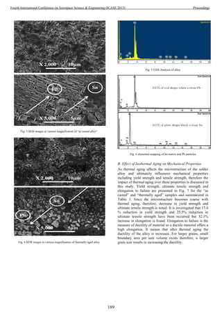
![Fig. 7 Mechanical properties of “as casted and “thermally aged” alloy
TABLE I. TENSILE TEST DATA
Specimen Tensile Test
Description
Condition
Alloy Without
Thermal
Aging
Alloy With
Isothermal
aging at 100C
up to 50 hours
Elongation @ Peak (mm) 1.0090 1.4870
Load @ Peak (N) 435.00 324.00
Strain @ Yield (%) 1.2333 1.3946
Strain @ Peak (%) 1.6817 2.0231
Stress @ Yield (N/mm2
) 16.856 13.919
Stress @ Peak (N/mm2
) 19.595 14.595
IV. CONCLUSIONS
It is concluded that from the results and observations that
the properties of the solder joint are highly microstructure
dependent and a strong relationship exists between
microstructural and mechanical properties. It has been
observed that thermal aging leads to coarsen the
microstructure of the alloys and ultimately affects the
mechanical properties. Mechanical properties including
yield strength and ultimate tensile strength decreases but
considerable increase in ductility have been examined. This
also concluded that thermal aging is closely related to
mechanical properties. Therefore, great care must be taken
regarding microstructure evolution and mechanical
properties in designing and developing solders but for
electronics green and environment friendly Pb free solders
must be introduced.
REFERENCES
[1]. Prymark, J., et al., Fundamentals of microsystems
packaging. ed. RR Tummala, Mcgraw-Hill Book
Company, New York, USA, 2001: p. 420.
[2]. Jung, K. and H. Conrad, Microstructure coarsening
during static annealing of 60Sn40Pb solder joints: I
stereology. Journal of Electronic Materials, 2001.
30(10): p. 1294-1302.
[3]. Kang, J. and H. Conrad, Microstructure coarsening
during static annealing of 60Sn40Pb solder joints:
II Eutectic coarsening kinetics. Journal of
Electronic Materials, 2001. 30(10): p. 1303.
[4]. Jung, K. and H. Conrad, Microstructure coarsening
during static annealing of 60Sn40Pb solder joints:
III intermetallic compound growth kientics. Journal
of electronic materials, 2001. 30(10): p. 1308-1312.
[5]. Basaran, C. and Y. Wen, Coarsening in Bga solder
balls: modeling and experimental evaluation.
Journal of Electronic Packaging, 2003. 125(3): p.
426-430.
[6]. Tang, H. and C. Basaran, Influence of
microstructure coarsening on thermomechanical
fatigue behavior of Pb/Sn eutectic solder joints.
International Journal of Damage Mechanics, 2001.
10(3): p. 235-255.
[7]. Ma, H., et al. The influence of elevated temperature
aging on reliability of lead free solder joints. in
Electronic Components and Technology
Conference, 2007. ECTC'07. Proceedings. 57th.
2007. IEEE.
[8]. Efzan, E. and A. Marini, A review of solder
evolution in electronic application. International
Journal of Engineering, 2012. 1(1): p. 2305-8269.
[9]. Frear, D., D. Grivas, and J. Morris, A
microstructural study of the thermal fatigue failures
of 60Sn-40Pb solder joints. Journal of Electronic
Materials, 1988. 17(2): p. 171-180.
[10]. Hacke, P., A. Sprecher, and H. Conrad,
Microstructure coarsening during thermo-
mechanical fatigue of Pb-Sn solder joints. Journal
of Electronic Materials, 1997. 26(7): p. 774-782.
[11]. Wassink, R.K., Soldering in Electronics, 1989.
Electrochemical Publication. 177.
[12]. Sharif, A. and Y. Chan, Dissolution kinetics of BGA
Sn–Pb and Sn–Ag solders with Cu substrates
during reflow. Materials Science and Engineering:
B, 2004. 106(2): p. 126-131.
[13]. Abtew, M. and G. Selvaduray, Lead-free solders in
microelectronics. Materials Science and
Engineering: R: Reports, 2000. 27(5): p. 95-141.
[14]. Zeng, K. and K.-N. Tu, Six cases of reliability study
of Pb-free solder joints in electronic packaging
technology. Materials science and engineering: R:
reports, 2002. 38(2): p. 55-105.
[15]. Needleman, H.L., et al., The long-term effects of
exposure to low doses of lead in childhood: an 11-
year follow-up report. New England journal of
medicine, 1990. 322(2): p. 83-88.
[16]. Noor, E.E.M., et al., Wettability and strength of In–
Bi–Sn lead-free solder alloy on copper substrate.
Journal of Alloys and Compounds, 2010. 507(1): p.
290-296.
[17]. Abadin, H., et al., Toxicological profile for lead.
Atlanta (GA): Agency for Toxic Substances and
Disease Registry, 2007.
190
Fourth International Conference on Aerospace Science & Engineering (ICASE 2015) Proceedings](https://image.slidesharecdn.com/conferenceproceedingsicase2015final1-160918062150/85/Conference-proceedings-199-320.jpg)
![[18]. Harrison, M., J. Vincent, and H. Steen, Lead-free
reflow soldering for electronics assembly.
Soldering & Surface Mount Technology, 2001.
13(3): p. 21-38.
[19]. Smith III, E.B., Environmental Impacts and
Toxicity of Lead Free Solders. op. cit, 1999: p. 2.
[20]. Sadiq, M., R. Pesci, and M. Cherkaoui, Impact of
thermal aging on the microstructure evolution and
mechanical properties of lanthanum-doped Tin-
Silver-Copper lead-free solders. Journal of
electronic materials, 2013. 42(3): p. 492-501.
191
Fourth International Conference on Aerospace Science & Engineering (ICASE 2015) Proceedings](https://image.slidesharecdn.com/conferenceproceedingsicase2015final1-160918062150/85/Conference-proceedings-200-320.jpg)
![Effect of aryl diazonium salt fucntionalization on the electrical properties of MWCNTs
and MWCNTs/CF reinforced polymer composite
Madni Shifa, Fawad Tariq, Kiran Ali, Rasheed Ahmed Baloch
Quality Management Directorate General
Pakistan Space and Upper Atmosphere Research Commission (SUPARCO)
75270 Karachi, Pakistan
Email: madnishifa@yahoo.com
Abstract— Multiwall carbon nanotubes (MWCNTs) are kind
of inert and hydrophobic material. These MWCNTs do not
disperse properly and tend to agglomerate in polymer matrices
due to high surface area and strong van der Waal forces
between themselves. Numerous studies have been conducted
in the last few years to resolve the issue of CNTs dispersion
and solubilization in polymer matrix through functionalization
process. However, most of the functionalization treatments
introduce defects and results in deterioration of electrical
properties. In this study, MWCNTs were covalently
functionalized by direct grafting of aryl diazonium salt
(BF4N2-C6H4-NO2) and effect of functionlization on electrical
behavior was assessed under applied electric field in an
electrolytic cell. The MWCNTs were dispersed ultrasonically
in 2-propanol which act as an electrolyte in electrolytic cell.
Voltage was applied on copper electrodes and movement of
MWCNTs inside the electrolyte was carefully observed in-situ
under optical microscope. In case of functionalized MWCNTs
(f-MWCNTs), no effect was observed under applied voltage
up to 100 V whereas un-functionalized MWCNTs (p-
MWCNTs) tend to align themselves in regular fashion
showing conducting behavior. SEM analysis was performed to
see the consequence of functionalization treatment on
morphology of MWCNTs and optical microscopy was carried
out to see the effect of functionalization on the dispersion of
MWCNTs in cured and uncured state of polymer matrix.
MWCNT/CF reinforced polymer composites were fabricated
using hand layup and compression molding technique. DC
electrical conductivity & electromagnetic interference
shielding effectiveness (EMI SE) testing were performed to
examine the effect of MWCNTs functionalization on
fabricated samples. Test results showed that the
functionalization degraded the electrical properties of
MWCNTs.
Keywords— Aryl diazonium salt, Functionalization,
Morphology of MWCNTs, SEM analysis, EMI SE
I. INTRODUCTION
Carbon nanotubes (CNTs) are carbon based advance nano-
materials with unique set of structure and properties.
Commonly two types of CNTs are being used i.e. single wall
carbon nanotubes (SWCNTs) and multi wall carbon nanotubes
(MWCNTs). Outer diameter of SWCNTs is around 1-2 nm,
while the outer shell diameter of MWCNTs ranges from 10-
100 nm. A typical length range of CNTs varies from 10-1000
μm and have aspect ratio of about 1000:1 [1]. CNTs are one of
the most promising materials known to men; their mechanical,
thermal and electrical properties are superb in all aspects [2].
Considering electrical properties of CNTs, electrical resistivity
is 0.4-0.7 Ωm, maximum current density 107-109 Acm-2
and
the band gap of CNTs is 0-0.7 eV depending upon their
nature. Owing to exceptional electrical properties in
conjunction with high aspect ratio and low density (one sixth
time lower than steel), CNTs have gained great interest for
developing lightweight electrically conductive polymer
nanocomposite [3, 4].
CNT/epoxy polymer composites have been widely used in
advance military aircrafts, fairings, missiles, personal
communications and electronic packaging in which CNTs act
as nano-fillers in epoxy matrix [5].High electrical conductivity
and nanometer size of CNTs imply very low level of
percolation threshold in CNT/epoxy nanocomposite [6].
Exceptional electrical properties of CNTs directly related to
high aspect ratio and defect free structure of CNTs. Advance
applications of epoxy polymer composite demands high
electrical conductivity, electromagnetic interference (EMI)
shielding and electrostatic dissipation (ESD) characteristics.
Electromagnetic waves produced from some electronic
component decrease the performance of nearby electronic
system by introducing noise, disturbance, data loss, etc.
Hence, there is an intense need to shield the sensitive
electronic circuits form undesired signals through EMI
shielding material. One basic criteria of EMI shielding
material is that it should be electrically conductive.
CNT/epoxy composite is found to be promising candidate in
this regard [4, 7-12].
However, one key issue of CNT based polymer
nanocomposite is the dispersion of CNTs in polymer matrix.
Dispersion includes separation of CNTs bundles and then
stabilization of CNTs in polymer matrix. As CNTs
agglomerates into bundles due to high surface area and these
bundles exhibits inferior properties as compare to individual
CNT. Another key challenge is the good interfacial bonding
between CNTs and polymer matrix. As CNTs are inert and
atomically smooth material so there is a lack of bonding
between polymer matrix and CNTs [13-15]. Best route to
overcome stated problems is to attach functional groups
through surface modification treatments of the CNTs. There
are numerous approaches to functionalize CNTs depending
upon their end use and the choice of functional group. Among
192
Fourth International Conference on Aerospace Science & Engineering (ICASE 2015) Proceedings](https://image.slidesharecdn.com/conferenceproceedingsicase2015final1-160918062150/85/Conference-proceedings-201-320.jpg)
![them, modification of CNTs through aryl dizonium salt is
more versatile and easy with variety of functional groups.
However, fucntionalization process induces defects and
decreases the aspect ratio of CNTs thereby degrading the
electrical properties like conductivity, EMI shielding and ESD
of CNT reinforced polymer composite [13, 16-18].
Most of the literature discusses the effect of acidic
functionalization on the electrical properties of CNT based
polymer composite. However, the effect of functionalization
treatment through aryl diazonium salt on electrical properties
of MWCNTs and MWCNT/CF reinforced composite has been
seldom reported. Therefore a detailed study has been
conducted in which MWCNTs were functionalized through
aryl diazonium salt to attach covalent functional group. Effect
of applied electric field on the electrical behavior of f-
MWCNT and p-MWCNTs in electrolyte has been in-situ
observed under light microscope and discussed here in detail.
Moreover, electrical conductivity and EMI shielding
effectiveness of f-MWCNTs/CF reinforced polymer
composite and p-MWCNTs/CF reinforced polymer composite
was also evaluated and compared.
II. MATERIALS AND METHOD
A. Materials
MWCNTs used in this study were purchased from Cheap
Tube Inc, US and were synthesized through CCVD (Catalytic
Chemical Vapor Deposition). Specification of MWCNTs
given by manufacturer: outer diameter 10-20 nm, length 10-30
µm, purity level > 95%, ash content <1.5%, specific surface
area 180-230 m2
/g and bulk density 0.22 g/cm3
. Specifications
details of carbon woven fabric which was used as
reinforcement in epoxy matrix are: areal density 325±5,
thickness 0.5±0.005 mm, breaking strength > 270Kg/5cm in
wrap direction, weave style satin 3, 3K tow and equal no of
threads in weft and warp direction. Thermoset epoxy resin
(Bisphenol-A) containing a reactive diluent was chosen as
matrix because of its long pot life, low viscosity and
multifunctional properties. Cycloaliphatic amine was selected
as hardener and used in the ratio of 10:3.5 by weight with
epoxy resin.
B. Functionalization of MWCNTs
Functionalization of MWCNTs was carried out through a
facile method in which 5-10 mg MWCNTs were dispersed in
acetronitrile through bath sonication. After 30 minutes of
sonication, 0.15-5 equivalent of diazonium salt (BF4N2-C6H4-
NO2) was added and stirring of mixture was carried out for 5
days at room temperature. Then whole mixture was filtered
through 0.45 micron size PTFE filter paper and washed
several time with acetronitrile to remove unreacted dizonum
salt. Functionalized MWCNTs were dried at room temperature
under vacuum for 24 h before use [19]. Functionalization of
MWCNTs was visually confirmed by dispersing 5 mg of
pristine and functionalized MWCNTs in water in different
tubes and kept for 24 h. After 24 h pristine MWCNTs were
settle down at the bottom of tube whereas the functionalized
Fig. 1. Schematic illustration of MWCNTs fucntionalization with 4-
Nitrobenzenediazonium tetrafluoroborate.
Fig. 2. Suspension of F (f-MWCNTs) and P (p-MWCNTs) in water after 24 h.
MWCNTs were remained suspended which confirmed the
functionlization of MWCNTs as shown in Fig. 2 whereas Fig.
1 demonstrates fucntionalization mechanism of MWCNTs.
C. Fabrication of MWCNTs/CF polymer composite
Functionalized MWCNT (0.2 wt% of matrix) was added to
ethanol and sonicated in sonication bath for 30 min to open up
MWCNTs bundles. Then epoxy resin was added to the f-
MWCNTs contained ethanol and further sonicated for 30 min
at 80⁰C to evaporate ethanol and disperse MWCNTs in epoxy
resin. Upon cooling of MWCNT filled epoxy resin, hardener
was added and solution was magnetically stirred for 10 min to
thoroughly mix the hardener in the solution. Finally,
193
Fourth International Conference on Aerospace Science & Engineering (ICASE 2015) Proceedings](https://image.slidesharecdn.com/conferenceproceedingsicase2015final1-160918062150/85/Conference-proceedings-202-320.jpg)
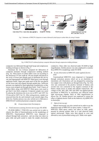
![Fig. 5. Picture of (a) Electrolytic cell (b) In-situ observation of MWCNTs
under electric field through light microscope.
examined after curing under the microscope to witness the
effect of curing cycle on dispersion state. Similar process was
carried out with p-MWCNTs containing epoxy resin.
D. DC electrical conductivity measurements
DC electrical conductivity of fabricated samples (both f-
MWCNTs/CF and p-MWCNTs/CF) was measured at room
temperature in accordance with ASTM standard D4496-98
and compared with the results of neat CF reinforced polymer
composite. Standard four point probe method was used to
determine the surface and volume conductivity via four Kelvin
pins and LCR meter.
E. EMI shielding effectiveness (EMI SE) test
EMI SE test was carried out in Anechoic chamber using
calibrated Vector Network Analyzer (Rohde & Schwarz) over
the frequency range of 7-14 GHz. Attenuation was measured
by recording S21 parameter (return loss) between source and
receiving antenna inside the anechoic chamber without any
sample. Then test sample was placed between the antennas
(source & receiving) and attenuation was again measured by
noting down the value of S21 parameter. The difference
between S21 values of sample and without sample gives the
value of attenuation (i.e. EMI SE) caused by the sample.
Attenuation is described in terms of shielding effectiveness
(SE), measured in decibel (db) and shows the reflective nature
of the sample. Testing was performed on equally dimensional
samples (150 x 75 x 2 mm) of f-MWCNTS/CF reinforce
polymer composite and p-MWCNTs/CF reinforced polymer
composite.
IV. RESULTS AND DISCUSSION
A. FE-SEM
Figure 6a and 6b shows the high resolution SEM images of
f-MWCNTs and p-MWCNTs respectively. Opening of end
caps and shortening of length was evident in case of f-
MWCNTs as shown in Fig. 6(a) while Fig. 6(b) demonstrates
that p-MWCNTs have long length and damage-free structure.
High aspect ratio and defect free structure of nanotubes is
prime requirement for exhibiting good electrical conductivity.
Morphological study through FE-SEM confirms that the aryl
diazonium salt functionlization has destroyed the physical
structure and decreased the aspect ratio of nanotubes, which in
turn decreased the electrical conductivity of MWCNTs.
B. In-situ observation of MWCNTs under applied electric
field
When DC electric field was applied up to 80 V no
significant effect was observed on MWCNTs under
microscope. However at 100 V fraction of p-MEWCNTs
moved from cathode to anode and network of nanotubes is
formed between electrodes. Under applied electric field
MWCNTs experience force due to polarization effect and
move from cathode to anode get discharged and absorbed on
the anode. Then adsorbed MWCNTs become the source of
adsorption of further nanotubes because of high electric field
at the tip which is connected to anode. In this way, conductive
pathway of p-MWCNTs is formed from anode to cathode
showing the high conducting nature of p-MWCNTs as shown
in Fig. 7 (a). In case of f-MWCNTs most of the nanotubes
under applied electric field attached to the anode without
development of conductive pathway because of imbalance
polarization effect due to structural damage during
fucntionalization process. Similar effect was also observed
with acid functionlized MWCNTs under applied electric field
by other researchers [20]. Transfer of electric current is not
possible between the electrodes without formation of
conductive path suggesting the poor electrical conductivity of
f-MWCNTs. Arrows head show the absence of conductive
pathway in Fig. 7 (b).
C. Optical microscopy
Figure 8 (a, b) shows the optical images of 0.2 wt % f-
MWCNTs and p-MWCNTs filled epoxy matrix in uncured
and cured state. Functionalized MWCNTs were more
uniformly distributed in the matrix and less amount of sub-
micron size aggregates were present as compared to p-
MWCNTs-epoxy matrix in uncured state. f-MWCNTs were
dispersed homogenously in matrix during sonication process
due to the bonding between epoxy and functional group
grafted on MWCNTs. However, in case of p-MWCNTs
homogenous distribution was difficult in matrix because of
195
Fourth International Conference on Aerospace Science & Engineering (ICASE 2015) Proceedings](https://image.slidesharecdn.com/conferenceproceedingsicase2015final1-160918062150/85/Conference-proceedings-204-320.jpg)

![Fig. 8. Optical images showing the dispersion of (a) f-MWCNTs and (b) p-
MWCNTs in uncured and cured state of polymer matrix.
Fig. 9. Volume and surface dc electrical conductivity of composite samples.
frequency and dependent on the type of MWCNTs addition.
Absorption and multiple reflections play an important role in
shielding against EM waves but dominating mechanism at
lower frequency is reflection which is directly related to
electrical conductivity of the sample [21]. Layered structure of
composite is responsible for the lost of EM waves at the
interface between carbon fabric and the matrix through
multiple reflection phenomena. And some part of EM waves
was absorbed by MWCNTs but mainly EM waves were
attenuated by reflection mechanism. As shown in Fig. 10 that
the p-MWCNTs composite demonstrated overall better EMI
SE which is governed by high electrical conductivity of p-
MWCNTs. For reflection of EM waves, 3D conductive
pathway is required which is better provided by p-MWCNTs
than f-MWCNTs. Maximum SE was observed by p-MWCNTs
sample at frequency range of 7-9 GHz with a peak about 70 db
at a 7.75 GHz frequency. However, in the frequency range of
10-11.5 GHz f-MWCNTs composite performed similar way as
p-MWCNTs sample and maximum SE about 46 db was
observed at 11.4 GHz in case of f-MWCNTs sample.
Minimum attenuation of about 14.8 db was observed at 13.7
GHz by p-MWCNTs sample and in case of f-MWCNTs
minimum attenuation of 9.4 db was attained at the frequency
of 13.5 GHz. From the test results, it can be inferred that p-
MWCNTs composite performed better than f-MWCNTs in
shielding EM waves in the whole tested frequency range with
the maxima at around 70 db.
V. CONCLUSION
Effect of functionalization by aryl diazonium salt on
electrical properties of MWCNTs was assessed through
applied electric field test in electrolytic cell, electrical
conductivity measurement and EMI SE test. Following
conclusions were drawn on the basis of test results:
SEM microscopy showed that the functionalization
process has damaged the physical structure of nanotubes.
It was found from the optical microscopy that the
dispersion of f-MWCNTs in the host matrix was
improved.
Amount of aggregates of MWCNTs increased upon
curing in both cases (p-MWCNTs & f-MWCNTs) but f-
MWCNTs showed more resistance to agglomerate
formation during curing stage.
It was deduced that high aspect ratio and defect-free
structure of MWCNTs is essential for formation of
conductive pathway under applied electric field. Pristine
MWCNTs aligned themselves in a regular fashion under
applied electric field whereas the f-MWCNTs do not
respond appreciably to the applied field.
DC electrical conductivity measurements showed that
the conductivity of f-MWCNTs was decreased as a result
of functionalization. The reason for deterioration in
electrical conductivity was attributed to the introduction
of defects in the MWCNT sidewalls and shortening of
length.
Pristine MWCNTs based composite sample outclassed
the f-MWCNTs composite in EMI SE testing over the
tested frequency range of 7-14 GHz.
3D conductive pathway formation of MWCNTs inside
the matrix is the prime requirement for exhibiting good
electrical properties and this in turn drastically affected
by the choice of functionalization procedure.
197
Fourth International Conference on Aerospace Science & Engineering (ICASE 2015) Proceedings](https://image.slidesharecdn.com/conferenceproceedingsicase2015final1-160918062150/85/Conference-proceedings-206-320.jpg)
![Fig. 10. Comparison of shielding effectiveness of f-MWCNTs/CF and p-MWCNTs/CF reinforced polymer composite.
ACKNOWLEDGMENT
Authors would like to thank Mr. Ahmed Bilal (Chairman,
SUPARCO) for approval and provision of facilities. The
authors also gratefully acknowledge Mr. Wasim Nawaz for
performing EMI testing and Ms Noureen Owais for
providing assistance in electrical conductivity measurements
of the samples.
REFERENCES
[1] Z.L. Wang, W. H. Manu and Dechang Li, “Structure and growth of CNT
films by Pyrolysis,” Cheml Phys Lett, V. 316(5,6) , pp-349, 2000.
[2] Ajayan PM, Zhou OZ, “Applications of carbon nanotubes. Carbon
Nanotubes,”. pp.391-425, 200.
[3] R. Lee, P. Nikolaev, H. Dai, P. Petit, J. Robert, C. Xu, Y. Hee Lee, S. G.
Ki, A. G. Rinzler, D. T. Colbert, G. E. Scuseria, D. Tomanek, and R, E.
Smalley, Thesis, “Crystalline Ropes of Mettaic Carbon Nanotubes,”
Science Vol. 273. No. 5274, pp. 483-487, 1996.
[4] Prabhakar R, Bandaru “Electrical Properties and Applications of Carbon
Nanotube Structures,” Reviews journal of Nanoscience and
Nanotechnology Vol.7, pp.1–29, 2007.
[5] Christopher Kingston, Richard Zepp, Anthony Andrady, et al. “Review-
Release characteristics of selected carbon nanotube polymer
composites,”CARBON Vol. 68 pp.33–57, 2014.
[6] Sandler JKW, Kirk JE, Kinloch IA, Shaffer MSP, Windle AH, “Ultra-
lowelectrical percolation threshold in carbon-nanotube-epoxy
composites.” Polymer, 2003, Vol. 44, pp.5893-9, 2003.
[7] Baughman R. H, Zakhidov A. A, de Heer, W. A, “Carbon nanotubes-the
route toward applications,” Science, Vol. 297, pp. 787-792, 2002. ISSN
0036-8075
[8] Bauhofer, W., & Kovacs, J. Z, “A review and analysis of electrical
percolation in carbon nanotube polymer composites,” Compos. Sci.
Technol., Vol. 69, pp. 1486-1498,ISSN 0266- 3538
[9] Singh BP, Choudhary V, Saini P, Mathur RB, “Designing of epoxy
composites reinforced with carbon nanotubes grown carbon fiber fabric
for improved electromagnetic interference shielding,” AIP Adv 2012;2:6
[10] Mathur RB, Singh B.P, Tiwari P.K, Gupta T.K, Choudhary V “
Enhancement in the thermomechanical properties of carbon fibre-carbon
nanotubes-epoxy hybrid composites,” International Journal of
Nanotechnology, Vol. 9, pp.1040-1049, 2012.
[11] Huang Y, Li N, Ma Y, Feng D, Li F, He X, et al, “The influence of
single-walled carbon nanotube structure on the electromagnetic
interference shielding efficiency of its epoxy composites,”
Carbon,Vol.45, pp.1614-21, 2007.
[12] Li N, Huang Y, Du F, He XB, Lin X, Gao HJ, et al. “Electromagnetic
interference (EMI) shielding of single- walled carbon nanotube epoxy
composites,” Nano Letters, Vol.6, pp.1141-5, 2006.
[13] Kannan Balasubramanian and Marko Burghard, “Chemically
Functionalized Carbon Nanotubes reviews,” Small, Vol. 1, No. 2, pp.
180–92, 2005.
[14] A.KANAPITSAS, C.TSONOS, “Study of electrical / dielectric and
thermomechanical properties of polymer–carbon nanotubes
nanocomposites,” In Proceedings of the 1st WSEAS International
Conference on NANOTECHNOLOGY.
[15] R.B. Mathu r, Shaila ja Pande, B.P. Sing h, T.L. Dhami, “Electrical and
Mechanical Properties of Multi-Walled Carbon Nanotubes Reinforced
PMMA and PS Composites,” POLYMER COMPOSITES-2008
[16] C.VELASCO-SANTOS, A.L.MARTINEZ-HERNANDEZ and V. M.
CASTANO, “Review Carbon nanotube-polymernanocomposites: The
role of interfaces Composite Interfaces,” Vol. 11, No. 8-9, pp. 567–586,
2005.
[17] Najiba Abdullah Al-Hamdani, “Preparation and Electrical Properties of
Epoxy Resin Reinforced with Functionalized Carbon Nanotubes,” IOSR
Journal of Applied Physics (IOSR-JAP) Volume 6, Issue 4 Ver. I, pp.
54-56, Jul-Aug. 2014
[18] Jeffrey L. Bahr, Jiping Yang, Dmitry V. Kosynkin, Michael J.
Bronikowski, Richard E. Smalley, and James M. Tour, “
Functionalization of Carbon Nanotubes by Electrochemical Reduction of
198
Fourth International Conference on Aerospace Science & Engineering (ICASE 2015) Proceedings](https://image.slidesharecdn.com/conferenceproceedingsicase2015final1-160918062150/85/Conference-proceedings-207-320.jpg)
![Aryl Diazonium Salts: A Bucky Pap,” J. Am. Chem. Soc,Vol. 123,
6536-6542, 2001.
[19] Anastasia A. Golosova, Christine M. Papadakis and Rainer Jordan
“Chemical functionalization of carbon nanotubes with aryl diazonium
salts” Mater. Res. Soc. Symp. Proc. Vol. 1362 © 2011 Materials
Research Society DOI: 10.1557/opl.2011.1141
[20] Abu Bakar Sulong, Nurhamidi Muhamad, Jaafar Sahari, Rizauddin
Ramli, Baba Md Deros, Joohyuk Park “Electrical Conductivity
Behaviour of Chemical Functionalized MWCNTs Epoxy
Nanocomposites” European Journal of Scientific Research ISSN 1450-
216X Vol.29 No.1, pp.13-21, 2009.
[21] Simon Rea,David Linton, Eddie Orr, Jonathan
McConnell“Electromagnetic Shielding Properties of Carbon Fibre
Composites in Avionic Systems,”Microwave Review, June, 2005
199
Fourth International Conference on Aerospace Science & Engineering (ICASE 2015) Proceedings](https://image.slidesharecdn.com/conferenceproceedingsicase2015final1-160918062150/85/Conference-proceedings-208-320.jpg)


![Figure 5 Simulated Reflection coefficient (S11) plot
The simulated reflection coefficient is less than -40 dB at
desired frequency while the impedance bandwidth is greater
than 100 MHz. Figure 5 shows the reflection coefficient plot.
IV. MEASUREMENT RESULTS
The proposed antenna is fabricated on wire cut machine in
order to have the slots fabricated with precision along with
maintaining very strict inter element spacing. The fabricated
antenna is shown in figure 6. The measured reflection
coefficient plot is shown in figure 7. Measured reflection
coefficient at desired frequency is -43 dB while impedance
bandwidth is 145 MHz. Antenna radiation pattern measurement
was carried out in Anechoic Chamber Test facility. Measured
azimuth and elevation cuts are shown in figure 8 and 9 the
measured gain at our desired frequency is about 20 dB.
Figure 6 Fabricated slotted waveguide antenna array
Figure 7 Measured Reflection coefficient
Figure 8 Measured Azimuth cut
Figure 9 Measured Elevation Cut
V. CONCLUSION
A resonant C band slotted waveguide antenna is designed,
fabricated and tested as per design requirement. Gain of the
antenna is approximately 20 dB with -43 dB reflection
coefficient value. Impedance bandwidth achieved is 145 MHz
for VSWR < 2.
VI. ACKNOWLEDGMENT
First I would like to thank Almighty for all His blessings
and providing me the strength for the successful completion of
this task. I would also like to thank SUPARCO for providing
me the opportunity and necessary support and guidance from
the team members for accomplishing this task.
VII. REFERENCES
[1] Antenna engineering Handbook Richard Clayton Johnson.
[2] Waveguide slot antenna array by Ronald A Gilbert BAE systems.
[3] W1 GHZ Microwave Antenna Book Paul Wade W1GHZ.
[4] Resonant length calculation and radiation pattern synthesis of
longitudinal slot antenna in rectangular waveguide By M.
Mondal, A. Chakrabarty Progress In Electromagnetics Research
Letters, Vol. 3, 187–195, 2008.
[5] A Design of Slotted Waveguide Antenna Array Operated at X
band Kuo-Lun Hung, His Tseng Chou. Wireless Information
Technology and Systems (ICWITS), 2010 IEEE International
Conference.
202
Fourth International Conference on Aerospace Science & Engineering (ICASE 2015) Proceedings](https://image.slidesharecdn.com/conferenceproceedingsicase2015final1-160918062150/85/Conference-proceedings-211-320.jpg)
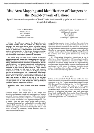

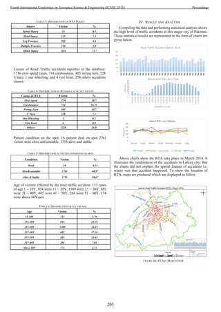
![For Cities like Lahore having major trading points may have
risk of more RTA. To understand this problem above map
illustrate the RTA comparison with commercial area. The map
clearly shows that the majority of accident happened near
commercial areas. Another picture of same issue reflect the
comparison of RTA density with commercial points (Figure XI).
This map demonstrates that red zones for accidents are nearby
commercial areas.
V. CONCLUSION AND RECOMMENDATIONS
This work gives an insight of the present scenario of the
traffic condition in Lahore and shows out the most accident
prone roads. The result shows that total road traffic accidents,
dense population areas, commercial areas are the important
variables to take into the consideration in examining traffic
accidents. Spatial data can be shared with transportation,
emergency services and other government organizations. This
spatial database can be helpful for expert system to make new
traffic plans and rules. It also provides accurate
recommendations to vehicle drivers, the police and to local
monitoring authorities. In order to curtail road traffic accident
on Lahore roads the following recommendations are necessary:
Drivers and bikers should be trained as the mean of effective
dealing with road accidents.
Traffic rules must be deployed by the law enforcement
agencies in the district and country.
Road safety education and seminars should be held by the
transport departments.
Drivers should drive within speed limit and with a speed
unswerving with road condition.
There must have proper parking plazas in all major
commercial zones and markets.
VI. ACKNOWLEDGMENT
This study is sponsored by The Urban Unit (Urban Sector
Planning and Management Service Unit USPMSU). The authors
would like to thanks Mr Niazm-ud-din (GIS Manager at Urban
Unit) for providing data and Mr. Ehsan Saqib (Sr. GIS
Development Specialist), Dr. Ather Ashraf (Sr. GIS Specialist)
for helping in different analysis.
VII. REFERENCES
[1] Bureau of Statistic Bos, “Punjab Development Statistics
2013”,www.bos.gop.pk.
[2] Deepthi Jayan.K, B. Ganeshkumar,”Identification of Accident Hotspot: A
GIS Based Implementation for Kannur District, Kerala” , vol. 1. ISSN
0976-4380.
[3] Dr, A.J.Aderamo, “Spatial Pattern of Road Traffic Accident Casualties in
Nigeria,”, vol. III, ISSN 2039-2117.
[4] Harnam Singh,A.D Aggarwal, “Fatal Road Traffic Accident among
Young Children,” J Indian Acad Forensic Med, 32(4), ISSN 0971-0973.
[5] The Urban Unit, USPMSU Lahore, www.urbanunit.gov.pk
FIGURE IX- RTA DENSITY COMPARISON WRT COMMERCIAL AREA
207
Fourth International Conference on Aerospace Science & Engineering (ICASE 2015) Proceedings](https://image.slidesharecdn.com/conferenceproceedingsicase2015final1-160918062150/85/Conference-proceedings-216-320.jpg)
![ANALYSIS OF RECENT DROUGHT BASED ON
NDVI AND METEOROLOGICAL DATA
A case study of Tharparkar district, Sindh
Muhammad Arslan1
, Rao Zahid2
, Badar Ghauri3
Department of Remote Sensing and GISc
Institute of Space Technology
Karachi, Pakistan
marslanhafeez100@gmail.com
Abstract— Thar region of Pakistan has often undergone short
and long period of drought. In this study, Satellite Remote
Sensing and meteorological data were used to detect the drought.
Agricultural drought was identified based on the pre and post
monsoon Normalized Difference Vegetation Index (NDVI) with
250meter spatial resolution from MODIS terra satellite from
2008 to 2014. Departure from the mean values of pre and post
monsoon NDVI was categorized to determine the agricultural
drought. Whereas meteorological drought was identified based
on the annual precipitation data for the same period provided by
the Pakistan Meteorological Department (PMD). Pre and post
monsoon mean NDVI for the year 2014 was then compared with
the previous years. Pre monsoon mean NDVI values of 2008 to
2013 was 0.115956, while post monsoon mean NDVI values of
2008 to 2013 were around 0.221801. On the other hand, pre and
post mean NDVI for the year 2014 were observed as 0.127617
and 0.156314 respectively. Mean post-monsoon NDVI value
drastically dropped in the year 2014. Satellite based mean NDVI,
PMD annual rainfall data and field observation showed that a
short term drought occurred in year 2014. This was also
confirmed by the local population during the field visit.
Keywords— Drought, MODIS, NDVI, precipitation.
I. INTRODUCTION
Drought is classified into four classes. Hydrological
drought, meteorological drought, agricultural drought and
socio-economic drought. No universal definition of drought is
still known. Drought is defined as a period of abnormally dry
weather which eventually affects in a change of vegetation of
an area [1]. Drought is also defined as it usually occurs when
the rainfall or runoff is found below a mean truncation level,
derived from the long term rainfall series [2]. For human
society and ecosystem drought is a significant adverse climatic
events. Since 1850, the mean global surface air temperature
has increased by 0.76o
C [3], by the end of the twenty first
century, it is expected that the temperature will increase by 1.5
o
C – 6.4 o
C [4]. Drought may increase under the warm climate
[5]. The frequency and the intensity of drought have increased
in past decades in many regions of the world [6, 7]. This
recurring of drought has negative impact in these areas in term
of annual loss of vegetation and food. Drought monitoring has
gained importance in many countries especially developed
countries due to the serious social, environmental and
economic ramifications [8]. Conventionally, drought
monitoring was based on meteorological station observations
that obviously does not have a continuous spatial coverage for
the monitoring of comprehensive drought. Most of the studies
have used satellite data to monitor hazards including, drought,
flood, earth quake and so on [9, 10]. Satellite data have
frequently been used to monitor and detect the drought
phenomenon [1]. Satellite data provides earth observation for
monitoring the impacts of drought in a precise and effective
way. There exists a time lag between precipitation events and
its response on the vegetation. The time gap between the
occurrence of precipitation and the time precipitation water
reaches the plant roots. It varies from 01 to 12 weeks
depending on vegetation type [11]. There are various studies
that have focused on NDVI and precipitation relationship.
This relationship varies spatially, when the NDVI values
changes with respect to precipitation [12]. Spatial distribution
and natural condition of vegetation are the function of
environmental variables such as precipitation. Strong
relationship is occurred between NDVI and rainfall [11].
Precise and consistent vegetation mapping is essential and
necessary for the management of water resources and
mitigation of drought events.
A. Objectives
to identify the NDVI and meteorological based drought.
to compare 2014 year recent drought with the previous
years
to evaluate the effects of drought in term of socio-
economic condition of the local people
II. MATERIALS AND METHODS
A. Study Area
Tharparkar district of Sindh province consists of deserted
land and its area is 19,638 square kilometers. Administratively
this district is divided into four talukas. These are Diplo,
Nagarparkar, Mithi and Chachro shown in Fig1. It has
208
Fourth International Conference on Aerospace Science & Engineering (ICASE 2015) Proceedings](https://image.slidesharecdn.com/conferenceproceedingsicase2015final1-160918062150/85/Conference-proceedings-217-320.jpg)
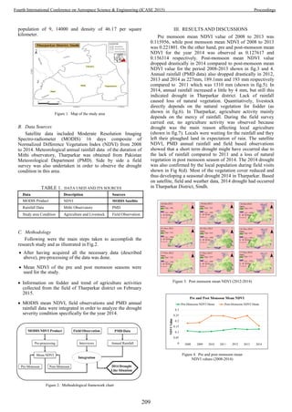
![Figure 5. Annual rainfall provided by PMD (2009-2014)
Figure 6. Means of food for the livestock
Figure 7. Reduction in agriculture
Figure 8. (a and b) Livestock of the area, (c) How local people collect water
(d) Interview from the local people related to drought (e and f) Showing
local people in the picture
IV. CONCLUSION
Drought is a recurring phenomenon and it can be examined
by satellites. Long term satellite data could help the severity
and onset of drought due to its spatial and temporal variability.
Effective and efficient drought mitigation could be achieved
through a well-defined drought monitoring system.
ACKNOWLEDGMENT
This research is part of a project named “Development of
Decision Support System for Drought Monitoring in Sindh”
funded by the Pakistan Higher Education Commission (HEC).
The authors acknowledged the financial grant of HEC.
Thanks are also due to Pakistan Meteorological Department
(PMD) for provision of data. We also thank NASA site for
giving data.
REFERENCES
[1] Kogan, Felix N. "Global drought watch from space." Bulletin of the
American Meteorological Society 78.4 (1997): 621-636.
[2] Dracup, John A., Kil Seong Lee, and Edwin G. Paulson. "On the
statistical characteristics of drought events." Water resources research
16.2 (1980): 289-296.
[3] Jones, P. D., Trenberth, K., Ambenje, P., Bojariu, R., Easterling, D.,
Klein, T., ... & Zhai, P. (2007). Observations: surface and atmospheric
climate change. In Climate Change 2007: The Physical Science Basis.
Contribution of Working Group I to the Fourth Assessment Report of
the Intergovernmental Panel on Climate Change, 235-336.
[4] Solomon, Susan, ed. Climate change 2007-the physical science basis:
Working group I contribution to the fourth assessment report of the
IPCC. Vol. 4. Cambridge University Press, 2007.
[5] Pachauri, Rajendra K., and A. Reisinger. "Synthesis Report." IPCC.
Ginebra (2007).
[6] Hulme, Mike, and Mick Kelly. "Exploring the links between
desertification and climate change." Environment: Science and Policy
for Sustainable Development 35.6 (1993): 4-45.
[7] McCarthy, James J. Climate change 2001: impacts, adaptation, and
vulnerability: contribution of Working Group II to the third assessment
report of the Intergovernmental Panel on Climate Change. Cambridge
University Press, 2001.
[8] M Amin, Owrangi, et al. "Drought monitoring methodology based on
AVHRR images and SPOT vegetation maps." Journal of water resource
and protection 2011 (2011).
[9] Anderson, James Richard. A land use and land cover classification
system for use with remote sensor data. Vol. 964. US Government
Printing Office, 1976.
[10] Peters, Albert J., et al. "Drought monitoring with NDVI-based
standardized vegetation index." Photogrammetric engineering and
remote sensing 68.1 (2002): 71-75.
[11] Chopra, Parual. "Drought risk assessment using remote sensing and GIS:
a case study of Gujarat." ME thesis, Indian Institute of Remote Sensing,
Dehradun & International Institute for Geo-information & Earth
Observation, the Netherlands (2006).
[12] Nicholson, S. E., and T. J. Farrar. "The influence of soil type on the
relationships between NDVI, rainfall, and soil moisture in semiarid
Botswana. I. NDVI response to rainfall." Remote Sensing of
Environment 50.2 (1994): 107-120.
210
Fourth International Conference on Aerospace Science & Engineering (ICASE 2015) Proceedings](https://image.slidesharecdn.com/conferenceproceedingsicase2015final1-160918062150/85/Conference-proceedings-219-320.jpg)
![Assessment of Urban Growth of Karachi: From A
Tiny Town to A Meta City of the World
Ali Jan Hassan1
, Mudassar H. Arsalan2
, Hira Fatima
Institute of Space and Planetary Astrophysics
University of Karachi
Karachi, Pakistan
1
Alijan.shaaan@gmail.com
2
mharsalan@uok.edu.pk
Abstract— Karachi is the only meta city of Pakistan and capital
of Sindh. It plays a key role in the country’s economy by
contributing 65% of total revenue. However the sustainability of
this city of lights is at risk due to mismanagement and
development without proper long term planning. The increased
urbanization has brought several severe issues such as increased
demographic density, management challenges, resource deficit
and ecological pressures, etc. The sprawl of the city is
uncontrolled spreading of urban developments. Remote sensing
data and GIS are now widely being used for change detection
analysis and applications. Urban sprawl is one of them, which
can be analyzed efficiently and cost effectively by utilizing
satellite data available online in the form of present as well as
historical images in different spatial resolutions.
In this study change detection technique was used to assess the
urban sprawl through the integration of historical maps with
Landsat-5 TM sensor image of 1989 and Landsat-8 OLI images
of 2014. With the aid of these images we monitored, measured
and analyzed the urban sprawl of Karachi. Despite of many
unsustainable conditions in the city, its population growth is
tremendous i.e. approximately 4 % per annum. This growth is
the result of the high natural increase as well as substantial
migrations from other parts of the country. It is assessed that the
living population in the mid 2014 was around 21 million, which
was far greater than of 1998 i.e. 9.2 million. In the last 25 years,
Karachi has extended around 15 percent at the rate of 2 square
kilometers per year to accommodate its increasing population
with considerable high density.
Index Terms— Urban sprawl, Change detection, Sustainability,
Satellite imagery, GIS, RS.
I. INTRODUCTION
Sustainability is not a new concept, it was discussed,
analyzed and even practiced at all levels, from country to
individual. The term ‘Sustainable Urban Developed’ (SUD)
emerged from the Brundtland Report [1], according to this
report, SUD is defined as “Development that meets the needs
of today without compromising the needs of the future.” Many
organizations such as UN-Habitat, WHO, EEA, etc., started to
work on SUD indicators. Indicators for sustainable
development provide valuable information, indicating rather a
development is on the way of sustainability or degradation [2].
Planners, developers and stakeholders use the SUD indicators
to better understand the current development situation as well
as to predict the future development scenario in context of
sustainability[3] Urban Sprawl is one of the main indicators of
SUD, that can determine the increment area of Urban land, as
well as the densification of the city [4]
Urbanization and Urban Sprawl are two different
terminologies. Urbanization is a process of increasing number
of people that migrate from rural to urban areas, results in the
physical growth of urban areas regardless of developments
occur horizontally or vertically [5], whereas Urban Sprawl is
defined as the expansion of urban area in the form of new
development on isolated tracts, separated from other areas by
vacant land [6]. The socioeconomic conditions of any place are
the driving forces for urbanization hence it occurs more
tremendously in areas that are economically well established
[7]. Urbanization is an inevitable process due to economic
development and rapid population growth [8]
In the last part of the 20th century and the beginning of the
21st century human population has increased tremendously. On
average, at every second 4 or 5 children are born, while 1 or 2
people dies, this rate of birth and death means a net gain of 2.5
persons (on average) on the Earth [9]. Unfortunately, this
increase has been occurring in the developing part of the world,
where lack of facilities, poverty, pollution and crime rate are at
its peak [9].
Pakistan is in the list of developing countries and is badly
affected by terrorism, energy crises and law and order situation
in the country [11]. It is an atomic power, bearing world’s
toughest army, having a vast amount of resources of coal, oil
and other minerals [12]. But due to miss-management,
irregularities and irresponsibleness of bureaucracy,
stakeholders and political leaders, the complete potential of the
resources is not being properly utilized [13]. Pakistan is the
world’s sixth most populous country today [14] With an
estimated population of 188 million, and 2.05 percent annual
211
Fourth International Conference on Aerospace Science & Engineering (ICASE 2015) Proceedings](https://image.slidesharecdn.com/conferenceproceedingsicase2015final1-160918062150/85/Conference-proceedings-220-320.jpg)
![growth rate, Pakistan is expected to become the fifth largely
populated nation by 2050 [14].
Table 1. World’s Most Populous Cities [14]
2014 2015
Country population
(Millions)
Country population
(Millions)
China 1368 India 1628
India 1226 China 1437
USA 320 USA 420
Indonesia 255 Nigeria 299
Brazil 203 Pakistan 295
Pakistan 188 Indonesia 285
A. Study Area
Today Karachi is the largest and most populous city of
Pakistan, lies in the south bounded by the Arabian Sea. It
covers a total area of 3600 square kilometers that includes
Built-up land, Vegetation Coverage, Industrial built-up,
commercial areas and a lot of recreational areas. The Karachi
port serves as a gateway for all the import/export activity by
sea. The industrial and economic activity in Karachi support
Pakistan a 65% of revenue [15]. Karachi appeared as a mega-
city with the beginning of this century with an exponential
growth in its population.
The residents of Karachi are blessed with the sea breeze
that blows throughout the year. Because it is close to the Sea
the temperature remains normal, the mean annual temperature
is in between, the wind normally blows towards North-East.
There are many commercial centers exist in the city, which
enabled the it to develop as an important industrial and
economic center that attract the people not only from Pakistan
but all over the world.
B. Objectives
The Objective of this study was to determine the urban
footprint for the year 1989 and 2014 using remote sensing data
and GIS, to figure out the extension of Built-up land within 25
years (1989-2010).
II. MATERIALS AND METHODS
The simple methodology adopted for this study comprises
of three steps: Data collection, data processing and urban
sprawl analysis. The brief account of these steps is given
below.
A. Data Collection
This study is an application of remote sensing and GIS in
Urban sprawl analysis. As recent as well as historical remote
sensing data is freely available on the internet. Further, using
GIS on this Remote sensing data different analysis can be
done efficiently and cost effectively. For this study Landsat 5
TM sensor clod free image of Karachi (Path-Row 152-42)
captured in November 1989 and Landsat 8 OLI sensor image
captured in January 2014 were acquired from the Landsat
archives available at the USGS website.
B. Data Processing
The pre-processing was carried out for the development of
AOI. Downloaded images of the study area were
geometrically corrected and projected to Universal Transverse
Mercator (UTM) projection system, zone 32. The spheroid
and datum were referenced to WGS1984.
C. Methodological Framework for Urban Sprawl
The change detection technique was adopted to assess the
change in land use and land cover (LULC) of the study area.
Collected and processed Landsat 5 image of 1989 and Landsat
8 image of 2014 were used while the main focus was on built-
Fig.1. Population growth in developing and developed nations, 1750
– 2100 [10]
Fig. 2. Study Area- Karachi, Pakistan
212
Fourth International Conference on Aerospace Science & Engineering (ICASE 2015) Proceedings](https://image.slidesharecdn.com/conferenceproceedingsicase2015final1-160918062150/85/Conference-proceedings-221-320.jpg)
![up area change. To extract the Urban built up the more
accurately supervised maximum likelihood classification was
done.
The Maximum Likelihood Classification is one of the
supervised classification approaches for pattern recognition in
which the probability of a pixel belonging to each of a
predefined set of classes is calculated, then pixel is assigned to
the class for which the probability is the highest [16]. ML is
based on the Bayesian probability formula:
P(x, w) = P(w|x) P(x) = P(x|w) P(w)
Where x and w are called events, P(x, w) is the probability
of coexistence of events x and w, while P(x) and P(w) are the
prior probabilities of events x and w and P(w|x) is the
conditional probability of event x given event w [16].
By carefully observing the patterns in the images, it was
concluded that the classification should be done for 4 classes
i.e. Urban Land, (including dense, green as well as sparse
Urban areas), Vegetation (including dense and sparse
vegetation as the study area had a vast mangrove forest towards
its south), Water bodies and Open/barren land.
Maximum Likelihood Classification was done on natural
color composite image (Band Combination 3, 2, 1) by training
100 samples of four classes distributed randomly in the image.
Classes were identified by visual interpretation. From this a
thematic map of four classes was generated. The same
procedure was applied to the other image.
1) Accuracy Assessment
To check the level of confidence in the classification results
an error matrix is usually generated. This is some time called
the confusion matrix, in which a matrix presents the
relationship between the classes in the reference maps and
classified images. Estimating classification accuracy enables us
to determine classification performance [16], but there is a lack
of information, because it leads to overall accuracy of the
classes not of individual class. To assess the accuracy of
individual class the concept of Producer’s and User’s accuracy
was used in this paper. A multivariate index, Kappa Coefficient
was also used to assess the difference between actual
agreement and change agreement [16].
III. RESULTS
Due to the highly favorable geographical location, Karachi
has always been a trade route for the merchants of India, but it
gained its importance in the British rule. The development of
perennial irrigation schemes by the British in Punjab and Sindh
mainly accounted for the growth of Karachi along with that the
development of railways, making the quick transportation of
the agricultural material that in turn increased in agricultural
production which was exported through Karachi which made it
the largest exporter of wheat and cotton to India [17].
In 1935, when Sindh separated from Bombay, Karachi
became the capital of Sindh, Government offices and trade
organizations were shifted from Bombay to Karachi. In 1947,
Pakistan got independence and Karachi became first capital
Pakistan.
Table 2 Karachi Population Growth [18]
Year Population Relative
change
No. of year in
between two
consecutive
census
Population
change
(%)
1901 136,297 136,297 10
1911 186,771 323,068 10 37
1921 244,162 430,933 10 30.2
1931 300,779 544,941 10 23.2
1941 435,887 135,108 10 44.9
1951 1,137,667 701,780 10 161
1961 2,044,044 906,377 10 79.67
1972 3,606,746 1,562,702 11 76.5
1981 5,437,984 1,831,238 9 50.8
1998 9,802,134 4,540,422 17 86.29
2001 13,500,000 3,697,866 3 37.7
2005 15,119,000 1,619,000 4 11.9
2014* 20,228,112 5,109,112 9 25.5
From the below graph we can see that the population of
Karachi was 9.2 million in 1998, there is a tremendous increase
of around 12 million in 2014[18].
Fig. 3. Methodological Framework of Urban Sprawl
Fig. 4. The Population Trend of Karachi 1901-2014
213
Fourth International Conference on Aerospace Science & Engineering (ICASE 2015) Proceedings](https://image.slidesharecdn.com/conferenceproceedingsicase2015final1-160918062150/85/Conference-proceedings-222-320.jpg)
![There was a significant increase of 161% from 1947-1951,
because of the migration of 600,000 refugees from India. The
settlement of those refugees was a challenge for newly built
local government. The refugees started to live on the periphery
and within the city itself, as a result the environment of Karachi
totally changed not only demographically but also ethnically
[17]. The irresponsibilities of higher authorities and lack of
planning and strategy the refugees unwillingly started to live in
squatter settlements and katchi abadis. After 1958, five master
plans have been developed for the development of the city, but
the implementation of those plans has always been an issue
because of political instability within the country.
The Karachi City, administratively is spread over an area of
approximately 3,600 sq. km. More than half of this area
(approximately 2455.5 acres) consists of vacant land. The land-
cover features such as water and vegetation, changes
throughout the year because it depends on the Climatic
conditions at a particular time. The Urban Built-up area has
extended from 343 square km in 1989 to 396 square km in
2014 that is a valuable change of 53 km in 25 years. This
reason behind this rapid increase in population within the city
is the migration from Interior Sindh, Punjab and Khyber
Pakhtoonkhuwa to find better opportunities in the mega city.
There is a 100 square km decrease in open land from which 50
sq. km land is converted into built-up land
The actual built-up land is 396 square km but as per
document figures by the City District Government of Karachi
(CDGK) [19], the built-up land was 1300 square km, it was a
combined built-up and developed open spaces. Developed
open spaces are those housing societies which were initiated in
1970s, 80s, and 90s, however, even after their infrastructure
developed they are vacant and hardly 5% occupied as shown in
table 3.
Table 3 Occupancy Status of New Housing Scheme, [19]
Serial. No. Name of
Scheme
Year of
Notification
Current
Occupancy
Status
(%)
1 Scheme no. 25-
A
1980 5%
2 Scheme no. 33 1971 20%
3 Scheme no. 42 1983 5%
4 Scheme – 43 1986 0%
5 Scheme – 45 1986 5%
From the table below, we can see that there is a 15 %
increase in built-up land and 3% decrease in open land. This
growth is mainly in built-up area and decrease in open land.
Table 4 Area Cover by each class for the years 1989 and 2014 in Sq. km
Serial
No.
Class Area
(1989)
Sq. km
Area
(2014)
Sq. km
Change
Sq. km
Change
(%)
1 Built-up 343 396 53 15
2 Open Land 2556 2455 -100 -3
3 Vegetation 748 849 -100 13
4 Water 1014 972 -41 -4
Table 5 Error Matrix of Land Cover (Karachi - 1989)
Class Built-
up
Open
Land
Veget
ation
Wat
er
Row
Sum
User's
Accura
cy
Prod
ucer's
Accu
racy
Built-
up
14 0 1 0 15 93.33 93.33
Open
Land
1 45 9 0 55 81.82 100
Veget
ation
0 0 10 0 10 100 45.45
Water 0 0 2 18 20 90 100
Colu
mn
Sum
15 45 22 18 100
Overall Accuracy 87% Kappa 0.328
Fig. 8. Land Cover Change of Karachi (1989-2014)
Fig. 9. Land Cover change % of Karachi (1989 - 2014)
214
Fourth International Conference on Aerospace Science & Engineering (ICASE 2015) Proceedings](https://image.slidesharecdn.com/conferenceproceedingsicase2015final1-160918062150/85/Conference-proceedings-223-320.jpg)
![Table 6 Error Matrix of Land Cover (Karachi - 1989)
Class Built-
up
Open
Land
Veget
ation
Wate
r
Row
Sum
User's
Accurac
y
Produ
cer's
Accur
acy
Built-
up
8 4 0 0 12 66.67 88.89
Open
Land
1 44 5 2 52 84.62 88
Vegeta
tion
0 0 9 0 9 100 64.29
Water 0 2 0 25 27 92.59 92.59
Colum
n Sum
9 50 14 27 100
Overall Accuracy 86% Kappa 0.3563
IV. DISCUSSION AND CONCLUSION
This study reveals that according to CDGK (2007) the
population of the city reaches to around 21 million and if we
consider the whole of Karachi area that is 3,600 km, the
population density is 6000 persons per square kilometer about
25% of its population has increased in last 10 years. However,
the Urban built-up area has extended from 343 square km in
1989 to 396 square km in 2014 that is a change of 53 square
km in 25 years. It shows the average annual growth rate is
slightly above 2 square kilometers per year. If we consider
average population density is 50,000 per square kilometer, the
city can accommodate only 0.1 million people every year.
However, it is not so, as the average population increase is 5
times higher than its accommodating capacity. It indicates the
pressure of population is more towards the existing
neighborhood in the form of densification and slum area's
growth. That results in depletion of resources, degradation in
environmental conditions and lack of recreational areas within
the city center. All these factors produce bad impacts on
social, environmental and economic conditions of the city and
makes difficult to achieve sustainable development.
This study was conducted to assess the conditions of Urban
Sprawl in Karachi that is an effective indicator of SUD,
however many other indicators can also be identified and
assessed, by implementing the techniques of RS and GIS.
Fig. 10. Growth of Karachi 1938-1992 [20]
215
Fourth International Conference on Aerospace Science & Engineering (ICASE 2015) Proceedings](https://image.slidesharecdn.com/conferenceproceedingsicase2015final1-160918062150/85/Conference-proceedings-224-320.jpg)
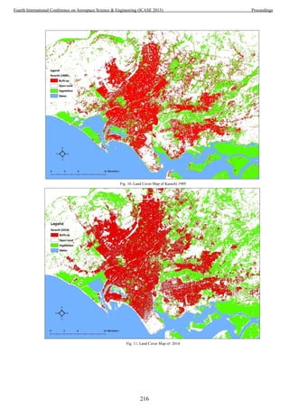
![REFERENCES
[1] World Commission, "Report of the World Commission on
Environment and Development: Our Common Future Acronyms
and Note on Terminology Chairman’s Foreword," ed: Oxford
University Press, 1987.
[2] M. Javadian, H. Shamskooshki, and M. Momeni, "Application
of sustainable urban development in environmental suitability
analysis of educational land use by using AHP and GIS in
Tehran," Procedia Engineering, vol. 21, pp. 72-80, 2011.
[3] N. Chrysoulakis, C. Feigenwinter, D. Triantakonstantis, I.
Penyevskiy, A. Tal, E. Parlow, et al., "A Conceptual List of
Indicators for Urban Planning and Management Based on Earth
Observation," ISPRS International Journal of Geo-Information,
vol. 3, pp. 980-1002, 2014.
[4] Sustainable Cities International, Indicators for sustainability-
How cities are monitoring Sustainability, 2012.
[5] UN, "United Nations Conference on Environment &
Development, Rio de Janerio, Brazil, 3 to 14 June 1992," 1992.
[6] J. I. IGBOKWE, I. C. EZEOMEDO, and E. J, "Investigation of
Urban Sprawl Using Remote Sensing and GIS: A case of
Onitsha and its Environments in Southeast, Nigeria,"
International Journal of Remote Sensing & Geoscience (IJRSG),
vol. 2, 2013.
[7] Boundless. (2015, July). The Process of Urbanization.
Available:
https://www.boundless.com/sociology/textbooks/boundless-
sociology-textbook/population-and-urbanization-
17/urbanization-and-the-development-of-cities-123/the-process-
of-urbanization-695-3433/
[8] S. Deep and A. Saklani, "Urban sprawl modeling using cellular
automata," The Egyptian Journal of Remote Sensing and Space
Science, vol. 17, pp. 179-187, 2014.
[9] W. P. Cunningham and M. A. Cunningham, Principles of
environmental science: inquiry & applications: McGraw-Hill,
2011.
[10] D. B. Botkin, E. A. Keller, and D. B. Rosenthal, Environmental
science: Wiley, 2012.
[11] I. Rana, "Foreigners driven away by terrorism, energy crisis," in
The Express Tribune, ed: @etribune, 2011.
[12] H. Naz, Environment of Pakistan, 2006.
[13] I. A. Sodhar. (2011, July). Pakistan Rich in Natural Resources
But Poor in their Management. Available:
http://jworldtimes.com/Article/92011_Pakistan_Rich_in_Natura
l_Resources_But_Poor_in_their_Management
[14] U. S. C. Bureau. (2011, July). International Programs, Country
Rank. Available:
https://www.census.gov/population/international/data/countryra
nk/rank.php
[15] A. Hassan. (2015, July). Ishaq Dar’s budget defies economic
vision: Karachi Chamber of Commerce and Industry. Available:
http://asianetpakistan.com/business-news/general-business-
news/203382/ishaq-dars-budget-defies-economic-vision-
karachi-chamber-of-commerce-and-industry-3/
[16] P. Mather and B. Tso, Classification methods for remotely
sensed data: CRC press, 2009.
[17] A. Hasan and M. Mohib, "The case of Karachi, Pakistan," 2003.
[18] Government of Pakistan, "Population Census Reports."
[19] CDGK, "Karachi Strategic Development Plan 2020," 2007
[20] M. S. Faruqui, Karachi, Physical Situation of Human
Settlements: Master Plan and Environmental Control
Department, Karachi Development Authority, 1982.
217
Fourth International Conference on Aerospace Science & Engineering (ICASE 2015) Proceedings](https://image.slidesharecdn.com/conferenceproceedingsicase2015final1-160918062150/85/Conference-proceedings-226-320.jpg)

![Identification of Post Disaster Scenario Using
Double Threshold Energy Detection
Shakeel Ahmed Waqas*
, Fahad Shamshad
Electrical Engineering Department, Military College
of Signals, National University of Science and Technology,
Islamabad, Pakistan
*
Shakeel_aw@yahoo.com
Nisar ali
Department of Telecommunication Engineering,
University of Engineering and Technology,
Peshawar, Pakistan
Abstract—The disaster can be naturally or manmade.
Telecommunication cellular system can be completely
destroyed by this disaster. The main priority is to provide
connection to disaster areas before the rescue team are
being arrived and save as much lives as possible. In this
paper, we presented a new algorithm which enable mobile
station to automatic detect the disaster scenario and switch
to emergency mode. We used double threshold energy
detection to reduce the false alarm. The performance of
proposed algorithm is evaluated using Monte Carlo
Simulation in term of probability of detecting post disaster
scenario, probability of miss detection and probability of
false alarm.
Keywords— Post Disaster Communication, Emergency
Mode, Normal Mode, Double Threshold, Energy Detection
I. INTRODUCTION
The telecommunication existing network can be
damaged or destroyed by manmade or natural disaster. In
result, that area will have no connection with national
communication infrastructure. 50% death occurs in two hours
after disaster [1]. The lives can be saved if there are some
mean of communication before the arrival of rescue team. The
survivors need urgent help after the disaster. Therefore, post
disaster communication is required to connect the disaster area
with whole country [1].
The post disaster communication can be achieved by
using Ad-hoc network. Ad-hoc network is used by many
researchers for emergency network. Wireless Emergency
Network can be obtained by multi hop Ad-hoc network. In
Wireless Emergency Network, there is ability of self-healing
[2]. But in disaster scenario, the resources are limited. Ad-hoc
network cannot reuse the available resources and also
unstable. In [1], the authors proposed that using cluster based
Ad-hoc network, the network become stable and resources can
be reuse. Thus, it increase the capacity. In cluster based
network, cluster head will forward the data of cluster
members. In [2], the authors proposed route repairing for
Wireless Emergency Network making it more stable, energy
efficient and reliable. In [3], authors presented cross layer
framework for the post disaster scenario. The authors
presented an adaptive protocol selector which select
appropriate protocol for each layer. Furthermore, the authors
in [4] proposed three algorithms using single threshold based
on cognitive radio, cellular network and artificial neural
network to detect the post disaster scenario. But there is
possibility of false alarm if the mobile is in deep fading area.
The authors in [5], proposed double threshold energy detection
algorithm for cognitive network and proved that false alarm
can be reduced by using double threshold.
In the paper, we presented a new algorithm using
double threshold for detecting post disaster scenario. We used
energy detection technique for the decision making. In this
paper, we presented the performance of our proposed
algorithm using BPSK modulation scheme over AWGN
channel. The performance is analyzed in term of probability of
detection post disaster scenario, probability of misdetection of
post disaster scenario and probability of false alarm. All the
results are evaluated using Monte Carlo simulation in
MATLAB.
II. SYSTEM MODEL
The system investigated in this paper is shown in
figure 1. Our system model consists of one mobile station and
two base stations. The mobile station is denoted by MS and
the two base stations are denoted by BS1 and BS2. MS is
connected with BS1 and BS2 is adjacent base station. The
distance between the MS and BS1 is denoted by d1. Similarly,
the distance between the MS and BS2 is denoted by d2. In our
system model, d1 is 2 km and d2 is 3 km. AWGN channel is
considered between MS, BS1 and BS2. The path loss
exponent is considered as n = 2. All the nodes (MS, BS1 and
BS2) are mounted with single antenna.
It is assumed that MS has already installed software
based identification module. There are two modes on which
219
Fourth International Conference on Aerospace Science & Engineering (ICASE 2015) Proceedings](https://image.slidesharecdn.com/conferenceproceedingsicase2015final1-160918062150/85/Conference-proceedings-228-320.jpg)
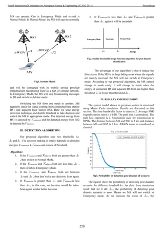
![probability increases. The post disaster scenario can be easily
detected if 0 is high.
The probability of miss detection of post disaster scenario
is shown in figure4. From the result, it is obvious that we will
surely miss the detection of post disaster scenario if the
threshold 1 is kept very low. Keeping the 1 low, then greater
probability of switching to Normal Mode and low probability
of switching to Emergency Mode. As the threshold 1
increases, then we can easily detect the post disaster scenario.
Therefore, the probability of miss detection decreases as the
threshold 1 increases.
The probability of false alarm of our proposed algorithm is
shown in figure5. To calculate false alarm we assume that SNR
Fig4. Probability of miss detection of post disaster
scenario
Fig5. Probability of false alarm
is 0 dB. According to our simulation result, it is stated that if
the thresholds are low then the probability of false alarm
increases. We get 100 % probability of false alarm at 0 dB
threshold.
As the threshold increases, the probability of false alarm
decrease. We get 0% false alarm for threshold equal to or
greater than 10 dB.
V. CONCLUSION
In this paper, we presented double threshold energy
detection algorithm for detecting post disaster scenario. This
algorithm enable mobile station to detect the post disaster
efficiently and take right decision in switching its mode from
normal to emergency or emergency to normal. Decision is
made by considering the energy of signals received from
connected Base station and from adjacent base station. The
performance is presented in term of probability of detection of
post disaster scenario, probability of miss detection of post
disaster scenario and probability of false alarm. In future, we
will work future on identification of post disaster scenario
using double threshold considering the adjacent channels.
REFERENCES
[1] Sonia Majid and Kazi Ahmed, “Cluster-based
Communications System for Immediate Post-disaster
Scenario” Journal of Communication, Vol. 4, No. 5, June,
2009.
[2] Xin Ma, Quan-yi Huang and Yan Kang, “A New Algorithm
for Stable Communication in Wireless Emergency
Network” International Conference on Computer and
Management, pp. 1-4, May 2011, Wuhan, China.
[3] Sonia Majid and Kazi Ahmed, “Cross-layer Framework
for Post-disaster Communications” IEEE International
Conference on Telecommunications and Malaysia
International Conference on Communications, 14-17 May
2007, Penang, Malaysia
[4] Sonia Majid and Kazi Ahmed, “CIP- Cognitive
identification of post-disaster communication” IEEE
conference on Telecommunications, pp. 43-47, June 2012,
Thailand
[5] Jinbo Wu, Tao Luo, Jianfeng Li and Guangxin Yue “A
Cooperative Double-threshold Energy Detection Algorithm
in Cognitive Radio Systems” IEEE conference on Wireless
Communications, Networking and Mobile Computing,
pp.1-4, Beijing, China.
[6] Haitao Wang, Lihua Song, Jianzhou Li, Jiaxin Deng,
“Wireless Self-organizing Emergency Communication
Network based on Network Clustering and Information
Ferry” , 2nd
Internation Conference on consumer
Electronics, Communications and Networks, pp. 3704-
3707, Yiching, China.
[7] Sonia Majid and Kazi Ahmed, “Post-disaster
Communications: A Cognitive Agent Approach” 7th
International Conference on Networking, pp- 23-30 Cancun
Mexico, April 2008.
[8] Marco Di Felice, Luca Bedogni, Angelo Trotta, Luciano
Bononi, Fabio Panzieri, Giuseppe Ruggeri, Gianluca Aloi,
Valeria Loscr, Pasquale Pace, “Smartphones Like Stem
Cells: Cooperation and Evolution for Emergency
Communication in Post-Disaster Scenarios” First IEEE
International Black Sea Conference on Communications
and Networking 2013 (IEEE BlackSeaCom 2013), Batumi,
Georgia.
[9] Jinbo Wu, Tao Luo and Guangxin Yue, “An Energy
Detection Algorithm Based on Double-threshold in
Cognitive Radio Systems” The 1st International Conference
on Information Science and Engineering (ICISE2009), pp.
493-496, Nanjing China.
221
Fourth International Conference on Aerospace Science & Engineering (ICASE 2015) Proceedings](https://image.slidesharecdn.com/conferenceproceedingsicase2015final1-160918062150/85/Conference-proceedings-230-320.jpg)
![Design and Analysis of Magnetic MEMS
Accelerometer for Inertial Navigation
M. Ameer Umar Malik, Umer Izhar, Umar Shahbaz, Javaid Iqbal
Department of Mechatronics Engineering
College of Electrical and Mechanical Engineering, NUST Islamabad, Pakistan
ameerumar@yahoo.com, umerizhar@yahoo.com
Abstract- Accelerometer is an important sensor of inertial
navigation system. Focus of new developments is a low cost, small
size sensor with high performance that meets the requirements of
navigation. In this paper a multi wafer magnetic MEMS
accelerometer design is proposed for inertial navigation.
Capacitive pick off is used to sense deflection of sensor mass and
permanent magnet & coil is used for rebalancing of deflected
mass of the sensor. Total two sides capacitive area of sensor is 18
mm2
with gap of 8µm. Permanent magnet with thickness of 330
µm and diameter of 700 µm and soft magnet material coating is
used. Out of plane coil with total 64 turns, 8 layers and cross-
section area 20µm x20µm is used. Fabrication process outlines
for both, the magnetic system and coils are proposed separately.
Stress analysis for flexures of sensing pendulum has been carried
out. Close loop frequency response analysis is carried out with a
proposed PID controller.
Key Words- Magnetic MEMS, Accelerometer
I. INTRODUCTION
Accelerometers are the important sensors of inertial
navigation systems. Traditional high accuracy
electromechanical accelerometers with quartz pendulum are
highly accurate with resolution of <1µg and one year
repeatability of ≤ 50 µg with input range of ± 50 g but also are
very expensive [1]. Whereas the best available MEMS devices
with input range of ±10g have resolution of up to 250 µg and
max repeatability of 25mg [2] but cost of MEMS sensors is
very low as compared to traditional electromechanical
accelerometers. Although accuracy of MEMS accelerometers
is yet not comparable to quartz flexure accelerometers but due
to their mass production process these provide very economical
solution particularly for low accuracy navigation applications.
MEMS accelerometers are widely being used in automobiles
but their accuracy is not enough for high accuracy inertial
navigation use. Variety of MEMS accelerometers are being
developed and reported for navigation applications. Most of
these are capacitive devices with electrostatic rebalancing
mechanisms. Recently reported ultra precision MEMS
accelerometer developed by Colibrys is also a capacitive
device working in close loop based on electro static
rebalancing [3-4].
In this paper a magnetic rebalancing mechanism for a
MEMS accelerometer is designed to get navigation grade
performance. Permanent magnets are being used in MEMS for
their repeatable performance. As the techniques of permanent
magnets fabrication in MEMS are being developed their use is
also increasing in high performance devices [5].
II. NAVIGATION GRADE ACCELEROMETERS
High performance accelerometers are required for high
accuracy navigation applications. Different performance
parameters can be specified for inertial navigation grade
accelerometers. In broad terms accelerometer performance can
be specified by two parameters i.e. bias and scale factor [1-6].
Accelerometers for navigation require high level of bias
stability, repeatability, temperature sensitivity and fine
resolution. Requirements of sensor parameters and comparison
for different requirements are discussed in [7]. Some of critical
parameters required for high accuracy navigation application
are given in table-1.
A variety of transduction mechanisms have been used in
MEMS accelerometers. Initially piezo-resistors were used in
MEMS accelerometers [7]. Then other principles like
capacitive, tunneling current, thermal, optical, electromagnetic
and piezoelectric etc are also utilized with their some
advantages and unavoidable disadvantages [8-9]. Capacitive
based sensing gives greater design flexibility than piezoelectric
quartz technology [6]. The capacitive devices are very popular
for their high precision.
TABLE:1 INERTIAL NAVIGATION REQUIREMENTS
Parameters Values
Range ± 25 g
Bias Stability ≤50 µg
Scale Factor Stability ≤ 50 ppm
Resolution ≤ 5µg
Frequency Range DC-200 Hz
Max. Shock in 1msec > 20 g
Temperature Range -40°C to 80 °C
III. PERMANENT MAGNETS IN MEMS
Use of electrostatic force is very common in
microelectronic systems due to its better force scaling at micro
scale level and also technology is highly developed as
compared to electromagnetic systems at micro level.[10]
Scaling differences of electrostatic and electromagnetic forces
222
Fourth International Conference on Aerospace Science & Engineering (ICASE 2015) Proceedings](https://image.slidesharecdn.com/conferenceproceedingsicase2015final1-160918062150/85/Conference-proceedings-231-320.jpg)
![is discussed in details by Edward P Furlani [5]. Magnetic field
from electromagnet unfavorably scales with diminishing sizing,
whereas the fields from permanent magnet are scale invariant.
Source of magnetic field in electromagnet is current but the
magnetic field in permanent magnet is residual magnetization
which arises at atomic level [5]. For actuation electromagnetic
is more stable for high force and for large gaps [11].
Use of permanent magnets was limited in MEMS due to
difficulties of their fabrication at micro scale level but now it is
increasing as different fabrication technologies are being
reported. Larger actuation distance can be achieved by using
magnets as compared to electrostatic actuation[5,12,13].
Permanent magnet is used in traditional navigation grade
electromechanical accelerometers. In MEMS accelerometer to
get µg resolution and low noise of accelerometer a heavier
proof mass is recommended and to rebalance this proof mass
an electromagnetic system with a permanent magnet can be
used.
IV. PROPOSED DESIGN
Accelerometer can be constructed and operated in open
loop or closed loop configuration. The basic construction of
accelerometer is such that a proof mass is suspended in case
and confined to a zero position by means of a spring, when the
acceleration is applied to the case of sensor, proof mass is
deflected with respect to its null position within the case, this
deflection of proof mass is proportional to specific applied
force along input axis. More accurate output can be obtained
by applying a rebalancing mechanism for deflected proof mass
[14]. This rebalancing mechanism can be either
electromagnetic or electrostatic. In traditional
electromechanical accelerometers the rebalance mechanism is
electromagnetic while in MEMS accelerometers it is
electrostatic.
A permanent magnet based MEMS accelerometer design is
proposed and analyzed. It is a three wafer design in which the
centre wafer with proof mass is sandwiched between two
symmetrical permanent magnet wafers. The bench mark of the
design is to use permanent magnet for rebalancing of proof
mass of MEMS sensor instead of electrostatic rebalancing.
Permanent magnet with volume of 0.7mm3 has been selected
to get bulk fabrication with powder size of 5~ 50 µm and this
can be accommodated in 500 µm thick wafer. Proof mass
includes the rebalance coils and capacitance area for pickoffs.
The designed proof mass has total area of 16 mm2 with
thickness of 500 µm and coils mass is additional. This heavy
proof mass results in a low Brownian noise [15] and greater
stability and repeatability. The proof mass is suspended by two
flexure beams attached to the fixed frame of centre wafer. In
response to the applied input acceleration the proof mass
deflects and change in capacitance is detected. One side
capacitance area for pickoff is 9 mm2
which is large as
compared to in plane MEMS accelerometers, this result in fine
pickoff resolution. Rebalance force is applied by the passing
current through the coils present on the proof mass. This
current is the output of the accelerometer giving information
about the acceleration applied to the system.
This can be modeled as a second order mass damping
system. Proof mass inertia is ‘J’, beams have effective stiffness
‘K’ and damping is ‘D’.
Transfer function is given as
H(s) =
Where ‘a’ is applied acceleration and ‘Θ’ is angular deflection
of proof mass.
Fig.1(a) Centre wafer with proof mass. (b) Three wafer device
For an applied input acceleration the total force depends on
the total proof mass of pendulum part. This input force is to be
balanced by coils. Lorentz force of the coils with current
flowing through is the rebalance force. The Lorentz force on a
conductor of length ‘L’ and with the current ‘i’ in an externally
generated magnetic flux density ‘B’ perpendicular to the wire
is given by F = Li × B. Rebalance force is directly proportional
to the magnetic field available in the working gap of coil. To
get maximum force magnetic field and coil placement need to
be optimized. Few analytical methods to get axial force
between a cylindrical magnet and a thick coil are discussed in
ref [16]. To get maximum magnetic field in working gap of
coil a magnetic loop is designed. Also to get maximum force,
magnetic field direction should be perpendicular to the current
flowing through the coil. Different configurations of magnetic
system with permanent magnet and soft magnet materials are
proposed, performance of each is evaluated to select the best
possible configuration. Magnetic flux density plot of selected
configuration is shown in in figure-2. Field variation in two
dimensions is simulated to get optimized location of coil.
Variation of flux density along z direction is plotted in figure-3.
The resolution of 10 µg is selected as a target. Stiffness
hinges are designed so that the smallest input of 10 µg
produces a deflection of 4.33e-7 rad. This minimum deflection
is used to estimate the overall gain required for pickoff system.
Overall pickoff gain of 2.32e6 is used and gain values of
different portions of pickoff system are calculated. Details are
discussed in closed loop analysis of system. All the parameter
values are calculated for this proposed design.
Stiffness - K= 2.32 g. mm / rad.
Damping - D = 1.16 g-s-mm.
Inertia - J = 0.0000307 g-mm-s2
223
Fourth International Conference on Aerospace Science & Engineering (ICASE 2015) Proceedings](https://image.slidesharecdn.com/conferenceproceedingsicase2015final1-160918062150/85/Conference-proceedings-232-320.jpg)
![Fig.2 Surface Plot of Magnetic Flux Density
V. FABRICATION PROCESSES
Design of this sensor system consists of three wafers as
shown in figure-4. Three wafers will be manufactured
separately and then bonded together to form a sensor. Two
wafers with permanent magnet are symmetrical. Coil is
fabricated on both sides of the third wafer. This third wafer is
to be fixed between two wafers with permanent magnet.
Fabrication processes for both magnet and proof mass coil are
proposed.
Permanent magnet is the key part in this design and fabrication
of permanent magnets has always been challenging in bulk
batch fabrication of MEMS. Permanent magnets are produced
by metallurgy process of mechanically pressing and heating.
But this process is yet not compatible with MEMS production
processes.
Fig.3 Magnetic Flux density along z direction
In MEMS conventionally permanent magnets are fabricated
by vapor deposition methods like sputtering, evaporation, pulse
laser deposition or by electrochemical deposition. By these
methods a layer of only few micrometers can be deposited.
Unconventional strategies like using magnetic powders of
5~50 micrometer sizes are being adopted to fabricate magnets
of required size at wafer levels. Permanent magnets fabrication
using magnetic powder and fabrication at wafer level is a
choice for this design.
Fig.4 Three Wafers of Magnetic MEMS accelerometer
Details and performance of this method is discussed in
details by Ololade D Oniku in ref [12]. Conventional
deposition of micro magnets with results is described in [13,
17]. Nd-Fe-B powder of size 15~ 50 µm can be used to get the
size required in this design and this can provide remanence Br
of 0.5 ~ 0.7 Tesla. Doctor’s blade technique as discussed in ref
[12] can be easily adopted at wafer fabrication for this design.
For fabrication of required size permanent magnet powder
fabrication is the best suited technique available. Fabrication
steps for complete magnetic system are proposed as
Cavity etching as per dimensions of magnet and
working clearance using DRIE process.
Coating of soft magnet material with thickness of 30 ~
40 µm.
Fill sacrificial material and form a cavity for permanent
magnet powder.
Permanent magnet fabrication in cavity using powder.
Coating of soft magnet material with thickness of 30 ~
40 µm above magnet.
Removal of sacrificial material to form working gap
for coil.
Fig.5 Permanent Magnet Fabrication (a) Cavity etching for soft magnet
coating. (b) Coating of soft magnet material. (c) Cavity forming for
permanent magnet. (d) Permanent magnet fabrication using powder. (e)
Coating of soft magnet material above magnet. (f) Removal of sacrificial
material layer to form working gap.
Fabrication of rebalance coil in multi layers is required on
the centre wafer. Fabrications of spiral coils have been reported
and one such multi layer coil with 36 turns in two layers has
224
Fourth International Conference on Aerospace Science & Engineering (ICASE 2015) Proceedings](https://image.slidesharecdn.com/conferenceproceedingsicase2015final1-160918062150/85/Conference-proceedings-233-320.jpg)
![been reported by Chong H Ahn, and Mark G Allen [18]. The
rebalance torquer coil required in this design is of 64 turns with
8 layers. The spiral pattern is Cu electroplated in 8 layers with
each layer separated by an insulating layer.
Fabrication steps for coil are proposed as
Pattern planner spiral coil on wafer and electroplate
copper coil layer.
Sputter 1st insulating layer then pattern for 02 copper
links for 2nd layer and electroplate copper links.
Pattern for planner spiral 2nd layer on 1st insulating
layer and electroplate 2nd copper coil layer.
Sputter 2nd insulating layer then pattern for 02 copper
links (different location as compared to step ‘b’) for
3nd layer and electroplate copper links.
Pattern for planer spiral 3rd layer on 2nd insulating
layer and electroplate 3rd copper coil layer.
Repeat this process to complete 8 copper coil layers.
Etching of insulating layer.
This coil is to be fabricated on both sides of wafer. Two
coils are connected in series therefore via connection across
wafer thickness is also made. Capacitive area coating and
connection pads are connected through two flexure hinges.
Fig.6 Coil Fabrication processes (a) Pattern planer spiral coil on wafer and
electroplate copper coil layer. (b) Sputter 1st insulating layer then
pattern for 02 copper links for 2nd layer and electroplate copper links.
(c) Pattern for planer spiral 2nd layer on 1st insulating layer and
electroplate 2nd copper coil layer. (d) Sputter 2nd insulating layer then
pattern for 02 copper links (different location as compare to step ‘b’) for
3nd layer and electroplate copper links. (e) Pattern for planer spiral 3rd
layer on 2nd insulating layer and electroplate 3rd copper coil layer. (f)
Repeat this process to complete 8 copper coil layers. (g) Etching of
insulation layer.
VI. ANALYSIS
A. Structure Stress Analysis
Sensor structure can be subjected to different forces during
manufacturing, storage and operational life. Analysis of
designed structure is carried out to evaluate its survival/
performances in different conditions. Flexures are the critical
parts that are under stress, in free condition when centre part is
not fixed between two wafers the centre part can bend freely
and subjected to maximum stress as shown in figure-7. Input
moment is defined as ‘M’ where ‘P’ is the mass of proof mass
part of centre wafer.
σ = as here are 2 flexure with section modulus ‘S’
σB = = 5.4012 Kg/ mm2
σA = = 6.3832 Kg/ mm2
Also deflection and angle of point ‘B’ in free condition are
calculated.
δB = ( + ) = 0.0111 mm
Θ = ( + ) = 0.0433 rad
Maximum deflection of point ‘C’ in free condition is calculated
as
δC = δB + Θ *2L = 0.2494 mm
But in assembled form this maximum deflection is restricted by
the fixed wafers. Maximum deflection possible in assembled
form is the gap provided for capacitance pickoff. Stress
analysis in the condition when centre wafer is fixed between
two fixed wafers is also carried out.
Fig.7 Static condition when centre wafer is free
This condition is analyzed by using static equilibrium
conditions and general solutions for deflection of statically
determinate beams [19].
RA + RB = nP --- 1
2L RB + M = nPL --- 2
– + ( – ) 2L = 0 --- 3
Moment is calculated by solving three equations and stress
due this moment ‘M’ is calculated σB = M/2S = 0.2381
225
Fourth International Conference on Aerospace Science & Engineering (ICASE 2015) Proceedings](https://image.slidesharecdn.com/conferenceproceedingsicase2015final1-160918062150/85/Conference-proceedings-234-320.jpg)
![Kg/mm2
. This stress is produced by application of 1g input and
is much less than the stress calculated in free condition. From
this analysis it is concluded that in assembled form the flexures
can bear much higher inputs before failure.
Fig.8 Static equilibrium condition when centre wafer is fixed between two
wafers.
Stress analysis and deflection analysis is performed in FEM
software and the results are verified. Results of FEM analysis
for the free condition are shown in figure-9.
Fig.9 FEM stress analysis for free condition
B. Mechanical Noise
Intrinsic noise of sensor can be due to mechanical and
electronic components. Mechanical–thermal noise due to
Brownian motion is usually analyzed for MEMS sensor and is
expressed total noise equivalent acceleration (TNEA) as
√
Where “kB” is Boltzmann’s constant, “T” is absolute
temperature, “w” is natural frequency and “Q” is quality factor
of flexure. High mass and quality factors lead to low noise.
Noise level of this design is estimates as 4.3µg/√Hz.
C. Closed Loop System Analysis
Resolution, measurement range, bandwidth, non linearity
and noise are the parameters to be analyzed for performance of
sensor. Simulation analysis of the designed sensor is performed
to find out the behavior of sensor for critical performance
parameters. Measurement range is the minimum and maximum
acceleration that sensor can response along its input axis with
certain accuracy. As spring stiffness is designed lowest to get
minimum acceleration detection, in open loop operation the
small distance between the moving capacitance surface and the
fixed surface limits the maximum measurement range.
Performance of open loop accelerometer is very limited
concerning to measurement range, bandwidth and linearity [20].
In close loop operation maximum measurement range is
limited by the feedback force that can be applied to rebalance
the deflected mass.
This design can only be operated in closed loop with high
gain pick off system with negative feedback. To achieve
desired system dynamics PID controller coefficients should be
carefully designed [21]. Stiffness of flexure is very small to
detect smallest input. The deflection produced by smallest
input is to be detected by the pickoff system. Gains of pickoff
blocks are calculated to detect smallest input. Closed loop
analysis of the design is performed in Matlab. Architecture of
close loop with a PID controller HCONT is shown in figure-10.
Pick off gain and other parameter used for control and analysis
are HCA = 10 A/V. HPA = 6880 pF/Arc-min, KPSA =
0,2V/pF with τPSA = 6.37e-6 sec. KTM =201 g-mm/A with
τTM = 3e-5 sec. Steady state sensitivity of sensor depends on
mass of pendulum ‘m’, length of pendulum ‘l’ and KTM of
rebalance torque system. As these parameters remain constant
for a sensor for this system steady state sensitivity if calculated
as Kss = ml / KTM = 0.1005 /201= 0.0005A.
Fig.10 Close loop architecture with output configuration
Fig.11 frequency response plot of closed loop architecture
-350
-300
-250
-200
-150
-100
-50
Magnitude(dB)
10
2
10
3
10
4
10
5
10
6
10
7
-450
-360
-270
-180
-90
0
90
Phase(deg)
Bode Diagram
Gm = 75.5 dB (at 1.66e+004 rad/sec) , Pm = Inf
Frequency (rad/sec)
i
a
pFα
HPA
(pF/arc- min)
Mi
n ΔM
V
-
+
HTM – Coil & Magnet
MTM
ml
HPSA
(V/pF)
HCA
(A/V)
i
Gp
HCONT
226
Fourth International Conference on Aerospace Science & Engineering (ICASE 2015) Proceedings](https://image.slidesharecdn.com/conferenceproceedingsicase2015final1-160918062150/85/Conference-proceedings-235-320.jpg)
![Frequency response analysis shows a bandwidth of 1.18e+4
rad/sec. Step response shows a rise time of 1.5154e-004 sec
with 27.5 % overshoot for this output configuration as is shown
in figure.12.
Fig.12 Step response of close loop architecture
Output response for a square input signal of 100 Hz is
shown in figure.
Fig.13 Response of close loop architecture
Maximum deflection of proof mass is limited by the
capacitance gap. In close loop operation the deflection of proof
mass must be minimum and less than the capacitance gap to
avoid electrical contact. To control the angular deflection the
close loop analysis is performed by transfer function as per
configuration is shown in figure 13.
Fig.13 Close loop architecture for angular deflection
Deflection for a step input signal of different g is shown in
figure-14. Maximum deflection at input signal of 10 g is less
than 1.5e-3 rad. Minimum deflection of proof mass ensures
reduced non linearity of output.
Fig.14 Deflection of sensor against step input
PID control parameters can be further optimized to achieve
best close loop performance of accelerometer.
VII. CONCLUSION
In this paper a new magnetic MEMS accelerometer is
designed with capacitive pickoff using permanent magnet and
coil for rebalancing of proof mass instead of traditional
electrostatic rebalancing of MEMS accelerometers. Resolution
of 10 µg can be achieved to fulfill navigation requirements.
Heavier proof mass results in reduced noise and also can be
rebalanced by electromagnetic force. Silicon structure provided
good thermal stability and magnets also provide low thermal
sensitivity as in traditional electromechanical accelerometers.
Permanent magnet can be fabricated in the bulk fabrication of
MEMS devices. Fabrication processes of permanent magnet
and coil are also proposed. In future study the device can be
fabricated and different performance parameters can be studied.
REFERENCES
[1] Honeywell, Q-Flex Navigation Accelerometers,
http://www.inertialsensors.com
[2] Colibrys Single axis analog accelerometer
http://www.colibrys.com
[3] Y.Dong, P.Zwahlen, A.M Nguyen,R. Frosio, F. Rudolf,“ Ultra
high precision MEMS accelerometer” Transducers’11, Beijing,
China,June5-9,2011.
[4] P. Zwahlen, Y Dong, A-M. Nguyen, F. Rudolf, J-M Stauffer,
P. Ullah, V. Ragot, “Breakthrough in High Performance Inertial
Navigation Grade Sigma-Delta MEMS Accelerometer”
[5] E.P Furlani, Permanent Magnet and Electromechanical
Devices, Material analysis and Applications Academic press 2001.
[6] Ralph Hopkins, Joseph Miola, Roy Setterlund, Bruce Dow,
William Sawyer, “The Silicon Oscillating Accelerometer: A High-
Performance MEMS Accelerometer for Precision Navigation and
Strategic Guidance Application” Institute of Navigation 61st
Annual Meeting Cambridge, MA, June 27-29, 2005.
[7] Navid Yazdi, Farrokh Ayazi, Khalil Najafi, “Micro-machined
Inertial Sensors” Proceedings of IEEE Vol. 86, No. 8 Aug 1998.
[8] Cenk Acar and Andrei M Shkel, “Experimental evaluation and
comparative analysis of commercial variable-capacitance MEMS
accelerometers”
Step Response
Time (sec)
Amplitude
0 1 2 3 4 5 6
x 10
-3
0
1
2
3
4
5
6
7
8
x 10
-4
System: Gcsys
Peak amplitude: 0.000638
Overshoot (%): 27.5
At time (sec): 0.000434
0.005 0.01 0.015 0.02 0.025 0.03 0.035 0.04 0.045 0.05
-1
0
1
2
3
4
5
6
x 10
-4
Linear Simulation Results
Time (sec)
Amplitude
0 0.005 0.01 0.015 0.02 0.025
0
0.5
1
1.5
x 10
-3 Step Response- Displacement of pendulum
Time (sec)
Amplitude(rad)
10 g
8 g
6 g
4 g
2 g
1 g
Gp
α
HTM
Coil & Magnet
i
HPA
(pF/arc- min)
HPSA
(V/pF)
HCA
(A/V)
pFVi
HCONT
ml
-
+
ΔM
Min
MTM
a
227
Fourth International Conference on Aerospace Science & Engineering (ICASE 2015) Proceedings](https://image.slidesharecdn.com/conferenceproceedingsicase2015final1-160918062150/85/Conference-proceedings-236-320.jpg)
![[9] Teodor Lucian Grigorie “The Matlab/Simulink Modeling and
Numerical Simulation of an Analog Capacitive Micro-
Accelerometer. Part1: Open loop ” MEMSTECH’ May 2008
Polyana UKRAINE
[10] Qingkun Zhou, Azhar Iqbal, Pinhas Ben-Tzavi, Dapeng Fan,
“Design, Analysis, and optimization of a magnetic micro
actuators” Proceedings of the ASME 2009, November13-19
Florida ,USA.
[11] Tsung-Shune Chin, “Permanent magnet films for application
in micro-electromechanical systems” Journal of Magnetism and
Magnetic Materials 209 (2000) 75-79.
[12] Ololade D Oniku, Benjamin J Bowers, Sheetal b Shetye,
Naigang Wang and David P Arnold “Permanent magnet
microstructures using dry-pressed magnetic powders” Journal of
Micromechanics and Microengineering published 12-june 2013.
[13] David P. Arnold., Naigang Wang., “Permanent Magnet for
MEMS”. Journal of Electromechanical Systems. Vol.18. No. 6,
December 2009.
[14] D.H.Titterton, J.L. Weston “Strapdown inertial navigation
technology” 1997 Peter Peregrinus Ltd.
[15] Ki-Ho Han , Young-Ho Cho, “ Self-Balanced Navigation-
Grade Capacitive Micro-accelerometer Using Branched Finger
Electrodes and Their Performance for Varying Sense Voltage and
Pressure ” Journal of Microelectromechanical systems, Vol. 12,
No.1, February 2003.
[16] Will Robertson, Ben Cazzolato, Anthony Zander, “Axial
Force Between a Thick Coil and a Cylindrical Permanent Magnet:
Optimizing the Geometry of an Electromagnetic Actuator” IEEE
Transactions on Magnetics Vol. 48 No.9, September 2012.
[17] Paul McGuiness David Jezersek, Spomenka Kobe, “100- µ-
thick Nd-Fe-B magnets for MEMS applications produced via a
low-temperature sintering route.”
[18] Chong H. Ahn, Mark G. Allen. “Micro- machined Planar
Inductors on Silicon Wafers for MEMS Applications”. IEEE
Transactions on Industrial Electronics Vol. 45, No.6 December
1998.
[19] Andrew Pytel, Ferdinand L. Singer, “Strength of Materials”
[20] Teodor Lucian Grigorie “The Matlab/Simulink Modeling and
Numerical Simulation of an Analog Capacitive Micro-
Accelerometer. Part2: Closed loop” MEMSTECH’ May 2008
Polyana UKRAINE
[21] Yin Liang, Liu Xiaowei, Chen Weiping, Zhou Zhiping, “High
resolution interface circuit for closed-loop accelerometer” Journal
of semiconductor Vol.32, No.4 April 2011.
228
Fourth International Conference on Aerospace Science & Engineering (ICASE 2015) Proceedings](https://image.slidesharecdn.com/conferenceproceedingsicase2015final1-160918062150/85/Conference-proceedings-237-320.jpg)
![Feasibility Assessment of Running JP-8 Fuel in
Diesel Engine
M. Shahan1
, Ali Sarosh2
,S. Javaid3
Department of Aerospace Engineering
National University of Sciences and Technology
Pakistan
1
heavy.cavalry.archer@gmail.com
2
alisarosh@cae.nust.edu.pk
3
saad.javaid@gmail.com
Abstract— Single fuel concept (SFC) demonstrates the need for
a safe and cost effective fuel that can be utilized by light-duty as
well as specialized heavy-duty vehicles. Logistics and pipeline
operations are greatly simplified when SFC is implemented for
vehicles. The study considers the technical feasibility of using
aviation fuel JP-8 in diesel engines. It compares the effects on fuel
injection, combustion, engine performance and emissions when
using JP-8 fuel instead of diesel inside a compression ignition
engine. The performance of both fuels at various operating
conditions is calculated. Besides this, a detailed review of chemical
kinetics of diesel and JP-8 and the effect of thermodynamic
properties on engine performance and emission is also presented.
In addition, combustion analysis of both the fuels is done in which
endothermic enthalpies due to air and water at various fuel-air
ratios are calculated. The results reflect that use of JP-8 in diesel
engine leads to a penalty of torque and fuel consumption primarily
due to lower density and viscosity. The reduced cetane number
causes increase in ignition delay and premixed combustion of JP-
8. Modifications to engine are proposed so as to match the
performance of both the fuels. Analysis show that implementation
of SFC is best suited for supplication in heavy-duty diesel engine
vehicles
Index Terms— JP-8, Enthalpy, Cetane number, Ignition delay,
Pre-mixed combustion
INTRODUCTION
Single fuel policy states that Jet Propellant 8 (JP-8) fuel must
be used in all air and ground battle field vehicles. According to
a research, 38.6% of army logistics supply consists of fuel. JP-8
is considered as a safe fuel for storage as well as during
operations. The US army and NATO will be using JP-8 fuel in
their aircrafts and ground vehicles till 2025[1].Using JP-8 in
ground vehicles offered my advantages. It reduced nozzle
fouling, exhaust emissions, water entrainment and microbial
growth inside the fuel tanks and increased fuel filter replacement
intervals, storage stability and enhanced oil change and filter
replacement intervals[2]. JP-8 is a jet fuel and belongs to the
class of kerosene. The flash point of JP-8 is 100 degrees
Fahrenheit. It is specified by MIL-DTL-83133. It was first used
by the NATO countries having a NATO code F-34. JP-8 is
almost similar to Jet-A1 fuel except that it has three military
additives. Tests were conducted on standard diesel cycle to give
an overall idea of replacing JP-8 fuel with diesel [3].Using JP-8
in ground battle field equipment leads to many advantages.
Logistics are simplified, oil lubricity is increased and exhaust
emissions are reduced. Single fuel concept also carried some
draw backs as well. Wear in fuel injection pumps exhaust valves
increases with the use of JP-8[4].Briefing charts regarding the
properties of JP-8 and other military fuels, different additives
that are used in fuels and their effect on fuel properties has been
presented by Schmitigal, Joel Tebbe and Jill in [5]. Similarly,
world jet fuel specifications have been given in [6]. A brief
review of the previous work done is this regard is given below:
Laboratory evaluation of JP-8 in diesel engine was
conducted as given in [7] in which JP-8 fuel was found
to be satisfactory for use in diesel engine but the
maximum engine power was reduced and leak in fuel
injection lines was observed. Compensation was done
by increasing thermal efficiency.
Engine testing with various blends of JP-8 was
conducted by April Covington with the perception that
in future an EPU will be designed to optimize engine
performance with JP-8[8]
Direct imaging and two color thermometry technique
was applied to verify the emission trends for JP-8 and
fossil diesel fuel in an optically accessible single
cylinder diesel engine. Image analysis focusing was
done to determine the characteristics of combustion.
Results verified that JP-8 emitted less smoke and
increased HC emissions [9].
Tests with petroleum, hydro processed and Fischer
Tropsch diesel and jet fuels were carried out in a direct
injection single cylinder diesel engine. Decrease in
ignition delay was quantified by increasing the derived
cetane number (DCN) of fuel. DCN decreased the
ignition delay[10]
Systematic study of ignition delay for different fuels in
2.44 L heavy duty single cylinder diesel engine was
conducted over a wide range of temperatures and
densities. Results indicated that fuel properties relating
to spray break have a nominal effect on the ignition
delay period [11].
229
Fourth International Conference on Aerospace Science & Engineering (ICASE 2015) Proceedings](https://image.slidesharecdn.com/conferenceproceedingsicase2015final1-160918062150/85/Conference-proceedings-238-320.jpg)
![ Oxides of nitrogen are harmful to the environment.
During combustion, oxides of nitrogen are formed
depending on the temperature and pressure. Hence
there is a need to reduce nitrogen oxide emissions from
diesel engine. Control on NOx emissions was obtained
by introducing varying quantities of cetane improver
additive in diesel fuel by enhancing the ignition quality
of fuel[12]
Mie-scattering technique is used in [13] to determine
the spray characteristics of fuels which includes spray
angle and spray tip penetration. Spray characteristics
are in turn correlated to combustion and emission
trends of fuels
Tests conducted on S60 engine revealed that JP-8
reduced nitrogen oxide and particulate matter
signatures in the exhaust emission and hence it is
environmentally friendly. Torque and fuel economy
penalty were compensated by increasing the pulse
width of fuel [1].
Tests results carried out on 60 kW direct injection
diesel engine running alternatively on diesel, JP-8 and
JP-8 treated with varying quantities 2-ethylhexyl
nitrate showed that ignition delay decreases with the
addition of cetane improver additives [14]. Sound
analysis regarding maximum heat release rate, engine
efficiency, cylinder pressure and exhaust were also
presented.
Analysis of the usage of blends of biodiesel and JP-8 in
diesel engine as given in [15] revealed that specific fuel
consumption decreases and NOx emissions increase by
increasing the quantity of biodiesel in test fuels. It was
concluded that these fuel blends can be effectively used
inside diesel engine.
METHODOLOGY
The basic aim was the verification of the results whether JP-
8 could be used as a replacement of diesel fuel in diesel engine.
Main objective was to understand the effects on combustion and
performance of engine when replacing diesel with JP-8 in diesel
engine. The approach which was followed is as described:
Analysis of actual diesel and JP-8 fuel properties was
done so that effect of each property on engine
performance can easily be quantified
Heat of combustion analysis of both fuels was
performed to obtain an indirect insight about the
thermodynamic parameters of fuels and power output
of engine when replacing JP-8 with diesel fuel
Dynamometer testing of engine is done to determine
the performance parameters such as torque and power
output
Assessment of fuel economy and strategies for
matching the power output with JP-8 with different
adjustments
FUEL PROPERTIES
Density effects the composition of fuel. Greater density
indicates lower volatility. Density of diesel is greater than JP-
8.It relates to the fuel pressure and dynamic start of fuel injection
in the engine[16]
Cetane number provides a measure of ignition delay of fuel.
This property indicates the quantity of straight chain
hydrocarbons in fuel. Lower cetane number implies lower
proportions of straight chain hydrocarbons and in turn longer
ignition delay[17].
Heating value of a fuel determines its energy content. Higher
heating value results in higher power output of engine [11]. JP-
8 has higher heating value than diesel but its lower density leads
to lower heating value on volume basis.
Viscosity provides a measure of resistance to flow. Working
of fuel injection pump is directly related to viscosity of fuel.
Pump wear and leakage in injection pumps increases due to
lower viscosity. Generation of spray pattern is also governed by
the viscosity of fuel[18].
Volatility of fuel is governed by distillation curve. Heavier
fuel results in incomplete vaporization and combustion and it
causes soot and smoke quantity to be increased[18].
Hydrocarbons having multiple benzene rings are called Poly
Aromatic Hydrocarbons (PAH’s). Diesel fuel contains higher
proportions of aromatics. Aromatics effect density, cetane
number and soot formation characteristics of fuel [17, 19, 20].
Environmental Protection Agency (EPA) requires that sulfur
content in the fuel should be as low as possible. JP-8 has lower
sulfur content as compared to diesel fuel so it is environmentally
friendly as compared to diesel.
CHEMICAL TESTING OF FUELS
Samples of JP-8 and diesel were taken and complete
chemical testing was done so that engine performance trends can
be co-related to chemical properties of fuels. Following results
were obtained from the chemical testing of JP-8.
Chemical testing of JP-8
Table 1 Test tests of JP-8
Test Method Test
Limits
Test
Result
Appearance
Color, Saybolt ASTM D156 Report +29
Composition
Total Acidity, mg
KOH/gm
ASTM
D3242
0.015
max
0.007
Sulfur, Total % mass ASTM
D4294
0.3 max 0.006
Sulfur, Mercaptan, %
mass
ASTM
D3227
0.003
max
0.0003
Volatility
Initial boiling point, °C ASTM D86 Report 146.9
10% vol. Recovery, °C ASTM D86 205 max 166.6
20% vol. Recovery, °C ASTM D86 Report 174.1
230
Fourth International Conference on Aerospace Science & Engineering (ICASE 2015) Proceedings](https://image.slidesharecdn.com/conferenceproceedingsicase2015final1-160918062150/85/Conference-proceedings-239-320.jpg)


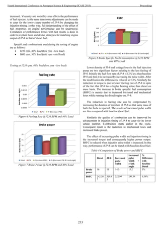
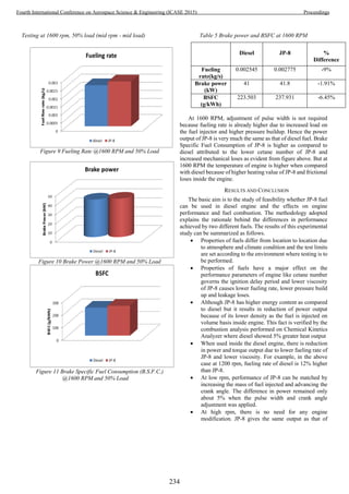
![Diesel because of higher pressure build up and load on
the fuel pump. But the engine heats up earlier because
of greater frictional loss.
Brake Specific Fuel Consumption for JP-8 is higher
than diesel fuel when used in diesel engine due to
higher frictional and mechanical loses and lower cetane
number of JP-8.
Analysis show that implementation of SFC is best
suited for supplication in heavy-duty diesel engine
vehicles
REFERENCES
[1] G. Fernandes, J. Fuschetto, Z. Filipi, D. Assanis, and
H. McKee, "Impact of military JP-8 fuel on heavy-duty diesel
engine performance and emissions," Proceedings of the
Institution of Mechanical Engineers, Part D: Journal of
Automobile Engineering, vol. 221, pp. 957-970, 2007.
[2] D. G. Weir, "Strategic Implications for a Single-Fuel
Concept," DTIC Document1996.
[3] A. Command, "JP-8: the single fuel forward: an
information compendium," Warren, MI, 2001.
[4] A. F. Montemayor, L. L. Stavinoha, S. J. Lestz, and M.
E. LePera, "Potential Benefits from the Use of JP-8 Fuel in
Military Ground Equipment," DTIC Document1989.
[5] J. Schmitigal and J. Tebbe, "JP-8 and other military
fuels," DTIC Document2011.
[6] E. Aviation, "World jet fuel specifications with avgas
supplement," Machelen: ExxonMobil Aviation, 2008.
[7] W. E. Likos, E. C. Owens, and S. J. Lestz, "Laboratory
evaluation of Mil-T-83133 JP-8 fuel in army diesel engines,"
DTIC Document1988.
[8] A. Covington, "The investigation of combustion and
emissions of JP8 fuel in an auxiliary power unit," 2011.
[9] J. Lee, H. Oh, and C. Bae, "Combustion process of JP-
8 and fossil Diesel fuel in a heavy duty diesel engine using two-
color thermometry," Fuel, vol. 102, pp. 264-273, 2012.
[10] S. Gowdagiri, X. M. Cesari, M. Huang, and M. A.
Oehlschlaeger, "A diesel engine study of conventional and
alternative diesel and jet fuels: Ignition and emissions
characteristics," Fuel, vol. 136, pp. 253-260, 2014.
[11] D. A. Rothamer and L. Murphy, "Systematic study of
ignition delay for jet fuels and diesel fuel in a heavy-duty diesel
engine," Proceedings of the Combustion Institute, vol. 34, pp.
3021-3029, 2013.
[12] K. Velmurugan and S. Gowthamn, "Effect of
CETANE Improver Additives on Emissions."
[13] J. Lee and C. Bae, "Application of JP-8 in a heavy duty
diesel engine," Fuel, vol. 90, pp. 1762-1770, 2011.
[14] G. Labeckas, S. Slavinskas, and V. Vilutiene, "Effect
of the Cetane Number Improving Additive on Combustion,
Performance, and Emissions of a DI Diesel Engine Operating on
JP-8 Fuel," Journal of Energy Engineering, 2014.
[15] A. Uyumaz, H. Solmaz, E. Yılmaz, H. Yamık, and S.
Polat, "Experimental examination of the effects of military
aviation fuel JP-8 and biodiesel fuel blends on the engine
performance, exhaust emissions and combustion in a direct
injection engine," Fuel Processing Technology, vol. 128, pp.
158-165, 2014.
[16] D. Kouremenos, D. Hountalas, and A. Kouremenos,
"Experimental investigation of the effect of fuel composition on
the formation of pollutants in direct injection diesel engines,"
SAE Technical Paper 0148-7191, 1999.
[17] Y. Kidoguchi, C. Yang, and K. Miwa, "Effects of fuel
properties on combustion and emission characteristics of a
direct-injection diesel engine," SAE Technical Paper 0148-
7191, 2000.
[18] T. J. Callahan, T. W. Ryan, L. G. Dodge, and J. A.
Schwalb, "Effects of fuel properties on diesel spray
characteristics," SAE Technical Paper1987.
[19] M. Lapuerta, J. Hernandez, R. Ballesteros, and A.
Durán, "Composition and size of diesel particulate emissions
from a commercial European engine tested with present and
future fuels," Proceedings of the Institution of Mechanical
Engineers, Part D: Journal of Automobile Engineering, vol.
217, pp. 907-919, 2003.
[20] T. L. Ullman, K. B. Spreen, and R. L. Mason, "Effects
of cetane number, cetane improver, aromatics, and oxygenates
on 1994 heavy-duty diesel engine emissions," SAE Technical
Paper 0148-7191, 1994.
.
235
Fourth International Conference on Aerospace Science & Engineering (ICASE 2015) Proceedings](https://image.slidesharecdn.com/conferenceproceedingsicase2015final1-160918062150/85/Conference-proceedings-244-320.jpg)
![1
Artificial Intelligence Robot
Muhammad Usman Saleem Muhammad Shaheer Sajid Muhammad Mohid
Collage of earth and atmospheric science LCAS LCAS
University of the Punjab Lahore Pakistan Lahore Pakistan
Lahore Pakistan shaheersajid15@gmail.com mmoohhiidd111@gmail.com
Osman.geomatics@gmail.com
Abstract: A.I.R or Artificial intelligence robot is a machine
which can be operated in two modes: manual and automatic.
This machine is specially designed to suit the needs for both
domestic and industrial purposes. A.I.R can be control and
operated within 10m of radius. A.I.R can detect obstacles
within distance of 1.5m. Then it will search the path without
obstacles. For automatics mode, it has been programed in such
a way, that we can define a line for its path then it will be
follow this path throughout its journey. Through the
concentration of smoke with in its domains, A.I.R can detect
the location where the smoke occurred. Its can transmit videos
to the receiver station through the camera installed on it. This
video can be investigated on a laptop. Manual control can be
done with the help of receiver.
Keywords: Control system, artificial intelligence, security
robots, and robotics.
I.INTRODUCTION
Now-a-days, Robotics has become one of the essential tools
aiming to make human lives much more compatible and
easier. Over the past years, many different mobile robots have
been created which directly affect the scientific community;
such as crawling and legged robot. This paper deals with a
wheel robot [1]. Similarly, A.I.R has specifications which too
aim for the same outcome. The basic functions of A.I.R
include; obstacle detection, path following, line following and
smoke/fire detectors. Multiple mobile robots have advances on
single mobile robot [2]. Hence we make it a multiple mobile
robot. Alongside, our robot has the ability to be controlled
directly by laptop and also by a remote controller. It may also
be viewed by a light weight wireless camera. At this moment,
it is worth mentioning that A.I.R, though small in size, has
been very efficiently to build, also making it a low cost
autonomous robot. This actually helps large companies to buy
these robots and get access to their numerous advantages and
applications, cheaply.
These functions hold immense importance for what we
hoped to achieve. The use of obstacle detectors and line
following functions actually put up a vast frame of use of the
A.I.R. Examples include, factories, Metro Politian [1] and
even for military purposes. The fire detectors and path
detector functions allow the robot to be used as a fire escaping
gadget, public safety, health care management system
respectively [3]. A.I.R can be operated automatically and
manually. Arduino is used to control A.I.R through laptop.
This robot is 60% recycled.
II. OBECTIVES
To build an artificial intelligence robot for the public safety,
road navigation, health care management system, fire
detection, industrial and military purpose. Primary objectives
were to connect this robot to laptop and get on the spot
information regarding to defense purposes.
III. METHODS AND METHODOLOGY
A. Remote Controller
A.I.R can be operated through remote control .It has a receiver
with its paired transmitters, which work on the principle of
radio waves. A transmitter sends radio waves to the receiver
which are then decoded and further processed (see fig 1).
There are four channels of the receiver which are attached to
the motor deriver circuit that derives the motor (see fig.2 & 6).
The radio circuit is a four data transceiver circuit, 2 controls
for each motor: forward and backward. Hence increasing
control over the robot.
B. Laptop Connection
In order to connect this robot to the laptop we have used
Arduino. The transmitter has a simple 4 channel encoder
circuit (see fig.2) that is connected to a development board
called Arduino (see fig. 3). The Arduino is programmed in
such a way to control it via a computer (see fig.4). Hence the
robot is a computer controlled one.
236
Fourth International Conference on Aerospace Science & Engineering (ICASE 2015) Proceedings](https://image.slidesharecdn.com/conferenceproceedingsicase2015final1-160918062150/85/Conference-proceedings-245-320.jpg)
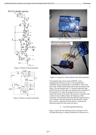
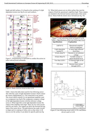


![7
ACKNOWLEDGEMENT
We would like to acknowledge the contribution of
Residence Officer, Prof. Dr. Sajid Rashid Ahmad,
Principal of Collage of earth and atmospheric science,
University of the Punjab, Lahore Pakistan for kind
contribution for the plagiarism evaluation for this study.
Also we would like to express our deepest gratitude to
Dr.Najam Abbas, Sectary ICASE 2015, Institute of Space
technology, Islamabad Pakistan for his very kind
contribution in publication of this effort to the public.
REFERENCES
[1] R. Chandra Kumar, M. Saddam Khan, D. Kumar, R.
Birua, S. Mondal and M. Kr.Parai, 'OBSTACLE
AVOIDING ROBOT – A PROMISING
ONE', International Journal of Advanced Research
in Electrical, Electronics and Instrumentation
Engineering, vol. 2, no. 4, p. 1430, 2013.
[2] S. Shan, 'Mobile Robots Based Intelligent Fire
Detection and Escaping System', JOURNAL OF
COMPUTERS, vol. 8, no. 5, p. 1298, 2013.
[3] D. Punetha, N. Kumar and V. Mehta, 'Development
and Applications of Line Following Robot Based
Health Care Management System', International
Journal of Advanced Research in Computer
Engineering & Technology, vol. 2, no. 8, p. 2446,
2013
242
Fourth International Conference on Aerospace Science & Engineering (ICASE 2015) Proceedings](https://image.slidesharecdn.com/conferenceproceedingsicase2015final1-160918062150/85/Conference-proceedings-251-320.jpg)
![An Intelligent Approach for Edge Detection in Noisy
Images using Fuzzy Logic
Izhar1,2
, Fayyaz3
1
Mechanical Engineering Department,
CECOS University of IT and Emerging Sciences,
Peshawar, Pakistan
2
Institute of Mechatronics Engineering,
University of Engineering and Technology,
Peshawar, Pakistan
1
izhar@cecos.edu.pk
R. Muhammad1
and N. Ahmed1
3
Department of Mechanical Engineering,
Pakistan Institute of Engineering and Applied Sciences,
Islamabad, Pakistan
Abstract—Edge detection has widespread applications in the
field of feature extraction, machine learning, computer vision,
pattern recognition, remote sensing and satellite image analysis.
In satellite images it detects various regions of interest for
different applications. Though it has useful applications, but it is
a complicated task and it becomes more arduous when it comes
to noisy images. This paper reports an intelligent approach for
edge detection in noisy images. The proposed edge detection
approach is based on fuzzy logic. The proposed algorithm
employs a 3 x 3 window mask and a fuzzy inference system. The
values acquired from the window mask are subjected to the fuzzy
rules for edge detection. The proposed technique is successfully
tested on noise free as well as on noisy images. The experimental
results are also compared with the reported established edge
detection techniques such as Laplacian of Gaussian (LOG),
Roberts, Prewitt, Sobel and previously proposed fuzzy based
algorithm. The proposed technique when tested on a grayscale
image having 24 dB ‘salt and pepper’ noise, detected 106 false
edge pixels. However, in comparison the reported edge detection
techniques like Sobel, Prewitt, LOG and previously developed a
fuzzy based technique have detected 3678, 4435, 835 and 2852
false edge pixels, respectively. From the experimental results it is
evident that the proposed edge detection technique provides
better solution to the edge detection problems in noisy images.
Index Terms— Edge Detection, Noisy Images, Fuzzy Logic
I. INTRODUCTION
Edges in an image are contours produced as a result of
abrupt or sudden alteration in any of the (multiple)
characteristics at pixel level. These changes could be observed
due to change in texture, color, shade or light absorption. These
characteristics could further lead in estimating the orientation,
size, depth and surface features in an image [1]. Edge detection
has numerous applications in the field of robotics, medical
image analysis, geographical science, pattern recognition, and
military technology [2]-[7] etc. It is often the case that images
embody high frequency noise or irrelevant data which inhibits
the detection of continuous edge points [8] since edge itself is a
composition of high frequency data. The noise produces false
flags, which often mislead the techniques for an edge.
Several algorithms are employed for the detection of edges
in images [9]-[14]. The motivation behind each technique is to
overcome the limitations in previous methodologies. The
conventional techniques like Canny, Sobel, Robert, Prewitt and
LOG [9]-[14] incorporate the use of spatial differential filters
utilising local gradient. These filters recognise an edge as an
abrupt change of grey scale pixel intensities. These techniques
are well established. These techniques process the data in
relatively short time and are computationally efficient.
However, the conventional techniques are susceptible to affect
generated by noise during edge detection.
Jiange and Bunke [15] proposed an approximation of scan
lines method for edge detection. The technique in comparison
to other segmentation techniques produced considerably good
results. Genming and Bouzong [16] proposed a 5x5 window
mask for the detection of edges based on a fixed threshold
level. However, their limitation was its inadaptability to
regions with varying greyscale due to fixed threshold point.
Latest techniques incorporate the use of artificial immune
system, artificial neural networks, genetic algorithms with
particle swarm optimization and ant colony optimization [17]-
[19].
Fuzzy set theory is another technique that is employed for
edge detection [20]-[21]. The method performs logical and
mathematical reasoning based on approximations rather than
crisp values. The technique therefore significantly reduces the
complexity of problems where fixed values cannot be
predicted. Kaur et al. [22] proposed a fuzzy logic based edge
detection technique employing a 2×2 window mask. Sixteen
fuzzy rules were defined for edge detection in the
algorithm .The results for edge detection was appreciable in
noise free images. However when subjected to noisy image the
technique detected the false edges produced due to noise as
well.
To address the short comings of the reported edge detection
techniques, a fuzzy logic based technique is proposed in this
work. The technique employs a 3×3 window mask guided by
fuzzy rule set for edge detection in noisy images. In our
previous work [23], we have used trapezoidal and gaussian
243
Fourth International Conference on Aerospace Science & Engineering (ICASE 2015) Proceedings](https://image.slidesharecdn.com/conferenceproceedingsicase2015final1-160918062150/85/Conference-proceedings-252-320.jpg)
![membership functions (MFs), however, in this work we have
preferred Pi and generalized bell shape MF to develop an
effective filter that is convenient to apply to both noise free and
noisy images. Moreover, algorithm developed in this work is
tested on noisy images having different noise levels.
II. PROPOSED METHODOLOGY
In Fig. 1 the conceptual framework of the proposed fuzzy
logic based edge detection is shown. The developed edge
detection technique for noisy images is based on fuzzy logic.
To extract the greyscale values of neighborhood pixels from
the input image, a 3x3 window mask is designed. The
grayscale values of the neighborhood pixels acquired from the
mask are pre-processed before applying to the fuzzy inference
system. A fuzzy inference system is designed that takes these
processed values as input. These values are subsequently
converted into the fuzzy plane. A fuzzy rule base is defined
that determine and show the edge pixels in the output image.
The output of the system is computed based on centroid
method and defuzzification is performed based on Mamdani
implication.
Fig. 1. Conceptual framework of the proposed edge detection approach.
A. Window Mask for Scanning the Image
A 3x3 window mask is designed for scanning the image, in
the proposed approach as shown in Fig. 2. The mask takes the
grayscale values, of eight neighbourhood pixels with the
central pixel, as the out pixel.
Before applying to the fuzzy inference system, the
grayscale values obtained from the mask are pre-processed.
Fig. 3 shows the processed mask, where
– for x = 1, 2, 3,…,8.
B. Fuzzy Membership Functions
In fuzzy inference system, MFs play a key role. In the
fuzzy set fuzziness is measured using MFs as they are the key
constituents of the fuzzy set theory. Based on the nature of
problem the type and shape of the MF should carefully be
selected as they have effects on the fuzzy inference system. In
the developed edge detection technique, for the input data, Pi
MFs are used, because they show reasonably improved results
with minimum error [24]. Moreover for the output data,
244
Fourth International Conference on Aerospace Science & Engineering (ICASE 2015) Proceedings](https://image.slidesharecdn.com/conferenceproceedingsicase2015final1-160918062150/85/Conference-proceedings-253-320.jpg)

![Table I lists the various terminologies and parameters of
both the input and output fuzzy sets.
TABLE I. PARAMETERS AND TERMINOLOGIES OF INPUT AND OUTPUT FUZZY
SETS
Linguistic Variable Parameter Range MF Type
Fuzzy Input ∆P1
Less [0 0 23 47]
[0 255] Pi MF
More [23 47 255 255]
Fuzzy Input ∆P2
Less [0 0 23 47]
[0 255] Pi MF
More [23 47 255 255]
Fuzzy Input ∆P3
Less [0 0 23 47]
[0 255] Pi MF
More [23 47 255 255]
Fuzzy Input ∆P4
Less [0 0 23 47]
[0 255] Pi MF
More [23 47 255 255]
Fuzzy Input ∆P5
Less [0 0 23 47]
[0 255] Pi MF
More [23 47 255 255]
Fuzzy Input ∆P6
Less [0 0 23 47]
[0 255] Pi MF
More [23 47 255 255]
Fuzzy Input ∆P7
Less [0 0 23 47]
[0 255] Pi MF
More [23 47 255 255]
Fuzzy Input ∆P8
Less [0 0 23 47]
[0 255] Pi MF
More [23 47 255 255]
Fuzzy Output G0
Non-Edge [3 2 10]
[0 255]
Generalized
Bell MFEdge [3 2 248]
D. Fuzzy Knowledge Base
Fuzzy knowledge base or rule base in fuzzy inference
system is a set of linguistic descriptions [25]. Fuzzy rule base
plays a key role in fuzzy inference system as it makes
conclusions related to classifying an input or stabilizing and
adjusting the output. Fuzzy rule base for the proposed edge
detection algorithm consists of the following linguistic
descriptions as listed in Table II.
III. RESULTS AND DISCUSSION
The developed edge detection technique is tested on a number
of grayscale images including noise free and noisy images. In
noise free greyscale images the developed technique has
successfully detected all type of edges as shown in Fig. 6. In
Fig. 6 (a) grayscale image of size 185 x 232 pixels having five
different regions covered by four boundary lines is shown. As
shown in Fig. 6 (c), the proposed technique for edge detection
has detected these four boundary lines (edges) successfully.
Similarly, as shown in Fig. 6 (b) the proposed method has
successfully detected edges in the greyscale (flower) image.
TABLE II. FUZZY KNOWLEDGE BASE FOR THE DEVELOPED EDGE DETECTION
TECHNIQUE
Rules Statement
R1
If ∆G1==More && ∆G2==More && ∆G8==Less then G0 ==
Edge
R2
If ∆G1==More && ∆G4==More && ∆G8==Less then G0 ==
Edge
R3
If ∆G2==More && ∆G3==More && ∆G8==Less then G0 ==
Edge
R4
If ∆G4==More && ∆G6==More && ∆G8==Less then G0 ==
Edge
R5
If ∆G1==More && ∆G2==More && ∆G7==Less then G0 ==
Edge
R6
If ∆G1==More && ∆G4==More && ∆G7==Less then G0 ==
Edge
R7
If ∆G2==More && ∆G3==More && ∆G7==Less then G0 ==
Edge
R8
If ∆G4==More && ∆G6==More && ∆G7==Less then G0 ==
Edge
R9
If ∆G1==More && ∆G2==More && ∆G9==Less then G0 ==
Edge
R10
If ∆G1==More && ∆G4==More && ∆G9==Less then G0 ==
Edge
R11
If ∆G2==More && ∆G3==More && ∆G9==Less then G0 ==
Edge
R12
If ∆G4==More && ∆G6==More && ∆G9==Less then G0 ==
Edge
Fig. 6. Tested images: (a) Image having four different regions, (b) Flower, (c)
Edge detection in image having four different regions, and (d) Edge detection
in flower image.
246
Fourth International Conference on Aerospace Science & Engineering (ICASE 2015) Proceedings](https://image.slidesharecdn.com/conferenceproceedingsicase2015final1-160918062150/85/Conference-proceedings-255-320.jpg)
![The developed edge detection technique has the advantage
of detecting edges in the noisy images as previously discussed
(in the introduction). This is verified by detecting edges in an
image having 24 dB ‘salt and pepper’ noise. To compute the
noise level in an image through peak signal to noise ratio
(PSNR), first based on equation (3) the mean square error
(MSE) is computed [26]-[27].
∑ ∑[ ] 3
Where and represents the input noise free and noisy
images respectively. While and indicates the total number
of rows and columns of the input images respectively. Finally
the expression for the computation of noise level becomes as in
(4).
[ ] 4
Where denotes the maximum possible intensity value of
the pixel in the input image. The value of for eight bit
unsigned integer data type image is 255.
The developed edge detection technique is applied to a size
500 x 232 pixels image having ‘salt and pepper’ noise at a level
of 24 dB. The simulation results are compared with other
conventional and reported edge detection algorithms as shown
in Fig. 7.
Fig. 7. Comparison of experimental results in noisy image, (a) Original image, (b) Noisy image, (c) Sobel edge detection (d) Prewitt edge detection, (e) LoG edge
detection, (f) Previously developed fuzzy based edge detection technique [22], (g) The proposed method.
From the experimental results it is clear that the proposed
fuzzy based edge detection algorithm has detected a very few
false edge pixels in comparison to the other reported edge
detection techniques. The number of false edge pixels detected
by different reported edge detection techniques, when
subjected to images having various noise levels is shown in
Fig. 8. From Fig. 8 it is evident that the developed edge
detection technique when subject to a noisy image of 500 x 232
size and 24 dB noise level has detected 106 false edge pixels,
while other edge detection techniques for instance, Sobel,
Prewitt, LOG, and previously developed fuzzy logic technique,
247
Fourth International Conference on Aerospace Science & Engineering (ICASE 2015) Proceedings](https://image.slidesharecdn.com/conferenceproceedingsicase2015final1-160918062150/85/Conference-proceedings-256-320.jpg)
![after fine tuning their parameters have detected 3678, 4435,
835 and 2852 false edge pixels respectively.
Fig. 8. False edge detected pixels in a standard image of 500 x 232 pixels: A
comparision.
IV. CONCLUSION AND FUTURE WORK
This paper proposes and demonstrates a fuzzy logic based
edge detection algorithm for noisy images. The developed
technique employs a 3×3 mask guided by fuzzy rule set for
edge detection in noisy images. The developed technique has
successfully detected all the edge pixels in noise free and
noisy images. The developed algorithm is also compared with
other conventional and previously developed fuzzy logic
based edge detection techniques. The developed edge
detection algorithm when subjected to a 500 x 232 size
grayscale image having 24 dB ‘salt and pepper’ noise has
detected a very few false edge pixels (106), while the reported
edge detection techniques like Sobel, Prewitt, LOG and
previously developed fuzzy logic have detected 3678, 4435,
835 and 2852 respectively. From the experimental results it is
obvious that in case of noisy images the proposed technique
provides better results.
In future an investigation on how to incorporate artificial
immune system with fuzzy logic to develop a hybrid
technique for edge detection is under consideration.
REFERENCES
[1] V. Torre and T. A. Poggio, “On edge detection.,” IEEE Trans. Pattern
Anal. Mach. Intell., vol. 8, no. 2, pp. 147–63, Feb. 1986.
[2] G. O. B. Siliciano, L. Sciavicco, L. Villani, “Modelling, Planning and
Control,” in Robotics, Springer, 2010, pp. 415–418.
[3] Sirikan Chucherd, “Edge detection of medical image processing using
vector field analysis,” in 11th International Joint Conference on
Computer Science and Software Engineering (JCSSE), 2014, pp. 58–63.
[4] H. Lin, P. Du, C. Zhao, and N. Shu, “Edge detection method of remote
sensing images based on mathematical morphology of multi-structure
elements,” Chinese Geogr. Sci., vol. 14, no. 3, pp. 263–268, Sep. 2004.
[5] R. Rulaningtyas and K. Ain, “Edge detection for brain tumor pattern
recognition,” in International Conference on Instrumentation,
Communication, Information Technology, and Biomedical Engineering
2009, 2009, pp. 1–3.
[6] A. A. Goshtasby, 2-D and 3-D Image Registration: for Medical, Remote
Sensing, and Industrial Applications. Wiley, 2005, pp. 34–39.
[7] A. Loft, K. E. Jensen, J. Löfgren, S. Daugaard, and M. M. Petersen,
“PET/MRI for Preoperative Planning in Patients with Soft Tissue
Sarcoma: A Technical Report of Two Patients.,” Case Rep. Med., vol.
2013, p. 791078, Jan. 2013.
[8] M. Setayesh, M. Zhang, and M. Johnston, “Effects of static and dynamic
topologies in Particle Swarm Optimisation for edge detection in noisy
images,” in 2012 IEEE Congress on Evolutionary Computation, 2012,
pp. 1–8.
[9] J. Canny, “A Computational Approach to Edge Detection,” IEEE Trans.
Pattern Anal. Mach. Intell., vol. PAMI-8, no. 6, pp. 679–698, Nov.
1986.
[10] C. Y. H. X. Zhang Jin-Yu, “Edge detection of images based on
improved Sobel operator and genetic algorithms,” in 2009 International
Conference on Image Analysis and Signal Processing, 2009, pp. 31–35.
[11] A. Rosenfeld, “The Max Roberts Operator is a Hueckel-Type Edge
Detector,” IEEE Trans. Pattern Anal. Mach. Intell., vol. PAMI-3, no. 1,
pp. 101–103, Jan. 1981.
[12] R. A. Kirsch, “Computer determination of the constituent structure of
biological images.,” Comput. Biomed. Res., vol. 4, no. 3, pp. 315–28,
Jun. 1971.
[13] L. Yang, X. Wu, D. Zhao, H. Li, and J. Zhai, “An improved Prewitt
algorithm for edge detection based on noised image,” in 2011 4th
International Congress on Image and Signal Processing, 2011, pp. 1197–
1200.
[14] F. Ulupinar and G. Medioni, “Refining edges detected by a LoG
operator,” in Proceedings CVPR ’88: The Computer Society Conference
on Computer Vision and Pattern Recognition, 1988, pp. 202–207.
[15] X. Jiang and H. Bunke, “Edge Detection in Range Images Based on
Scan Line Approximation,” Comput. Vis. Image Underst., vol. 73, no. 2,
pp. 183–199, Feb. 1999.
[16] C. Genming and Y. Baozong, “A new edge detector with thinning and
noise resisting abilities,” J. Electron., vol. 6, no. 4, pp. 314–319, Oct.
1989.
[17] A. Naumenko, V. Lukin, and K. Egiazarian, “SAR-image edge detection
using artificial neural network,” in 2012 International Conference on
Mathematical Methods in Electromagnetic Theory, 2012, pp. 508–512.
[18] O. P. Verma and R. Sharma, “An optimal edge detection using universal
law of gravity and ant colony algorithm,” in 2011 World Congress on
Information and Communication Technologies, 2011, pp. 507–511.
[19] M. Setayesh, M. Zhang, and M. Johnston, “Effects of static and dynamic
topologies in Particle Swarm Optimisation for edge detection in noisy
images,” in 2012 IEEE Congress on Evolutionary Computation, 2012.
[20] C.-C. L. Yau-Hwang , Chang-Shing Lee, “A new fuzzy edge detection
method for image enhancement,” in Proceedings of 6th International
Fuzzy Systems Conference, 1997, vol. 2, pp. 1069–1074.
[21] S. E. El-Khamy, M. Lotfy, and N. El-Yamany, “A modified fuzzy Sobel
edge detector,” in Proceedings of the Seventeenth National Radio
Science Conference. 17th NRSC’2000 (IEEE Cat. No.00EX396), 2000.
[22] K. Kaur, V. Mutenja, and I. S. Gill, “Fuzzy Logic Based Image Edge
Detection Algorithm in MATLAB,” Int. J. Comput. Appl., vol. 1, no.
22, pp. 57–60, Feb. 2010.
[23] S. Mandal, J. Choudhury and S. Chaudhuri, “In Search of Suitable
Fuzzy Membership Function in Prediction of Time Series Data,” IJCSI
International Journal of Computer Science Issues, vol. 9, no.3, 2012.
[24] Izhar, I. U. Haq, K. Shah, T. Khan, K. Azam, S. Anwar, “Fuzzy Logic
Based Edge Detection for Noisy Images” Technical Journal, UET
Taxila, vol. 20 (SII), no. II (S), 2015.
[25] O. Karray, and C. De Silva, Soft computingand intelligent systems
design: theory, tools and applications, Pearson Addison Wesely, Essex
CM20 2JE, England, 2004.
[26] F. Luisier, T. Blu and M. Unser “Image Denoising in Mixed Poisson-
Gaussian Noise,” IEEE Transactions on Image Processing, vol. 20, no.
3, pp. 696-708, 2011.
[27] J. Liu, Z. Huan and H. Huang, “Image restoration under mixed noise
using globally convex segmentation,” Journal of Visual Communication
and Image Representation, vol. 22, no.3, pp. 263-270, 2011.
248
Fourth International Conference on Aerospace Science & Engineering (ICASE 2015) Proceedings](https://image.slidesharecdn.com/conferenceproceedingsicase2015final1-160918062150/85/Conference-proceedings-257-320.jpg)
![A Survey of Active ITU-R P-Series Propagation
Models
Sundus Najib1
, Ibrar Ali Khan2
, Muhammad Waleed
Aftab1
, Naveed Mufti1
1
Department of Telecommunication Engineering
2
Department of Electrical Engineering
University of Engineering and Technology, Peshawar
Peshawar, Pakistan.
sundus.najib@gmail.com
Rafia Mehreen
Department of Telecommunication Engineering
University of Engineering and Technology, Taxila
Taxila, Pakistan
Abstract— ITU-R (International Telecommunication Union)
P-series (Propagation-series) recommendations encapsulate the
propagation models and data vital for modeling of any radio
communication path, including space and terrestrial paths. For a
new researcher, an understanding of these recommendations
prior to their application in various scenarios is desirable. This
paper presents an introduction to propagation, radio channel
impairments and previous review studies, followed by review of
thirty-one recommendations applicable to numerous
indoor/outdoor propagation scenarios. It is observed that some
outdoor propagation models can be used for partial indoor
scenarios while the only indoor model provided by ITU-R series
can also be used for various outdoor setups. Certain
recommendations are interconnected with other
recommendations, developing a need for their comprehensive
study.
Keywords— ITU-R; Radiowave Propagation; Indoor/Outdoor
propagation models; P-Series.
I. INTRODUCTION
The International Telecommunication Union (ITU)’s
Radiocommunication Sector primarily works for global
harmonization of the use of radio frequency spectrum. In
addition to supervising the international radio spectrum
regulation and satellite orbits resources, ITU-R also develops
Radiocommunication standards and recommendations for the
efficient use of spectrum in Radiocommunication systems [1].
Radio spectrum has a vast range of applications in
considerable operational environments. Three main
mechanisms namely refraction, diffraction and scattering
make it possible for the radio waves to propagate beyond the
horizon in terrestrial communication [2]. Certain factors can
have different effects along the path of transmission, resulting
in the loss of information signal. For communication to
succeed, modeling of the radio spectrum/system to overcome
and minimize these channel impairments is vital [3].
Many modeling techniques for radio channel modeling
have been put forth by researchers from time to time for
effective radio communication. ITU-R encourages research
and investigations into different aspects of
radiocommunication by proposing questions (ITU-R
Questions), constituting Study Groups, seeking input from
Member States and Industry and ultimately converting
different inputs into ITU-R Recommendations. It takes years
of research and hard work for developing and modifying each
recommendation, thus making it valid and reliable. The
Recommendations are further classified on the basis of
‘services’ [1]. There are currently seventy-eight active
recommendations dealing with Radiowave Propagation [4].
Each recommendation is valid for specific conditions and
frequency bands. At the time of writing, there is no known
comparison/review of the ITU-R Recommendations pertaining
to propagation. It is felt that, for a new researcher, it becomes
difficult to understand, sort and pin point the most relevant
ITU-R propagation model for his/her modeling/
scenario/investigation. This review paper is aimed at
providing a comparative summary of the propagation models
contained within the ITU-R P-series Recommendations. It is
hoped that this would help the researchers to get an overview
of the propagation models within the P-series and enable them
to select the most relevant recommendation for modeling their
specific scenario.
The order of remaining paper is as follows: Section-II
explains basic propagation mechanisms, followed by radio
channel impairments. Section III discusses previous review
studies while in Section-IV, ITU-R indoor and outdoor radio
propagation models are discussed. Finally Section-V and
Section-VI puts forward the guidelines and conclusions along
with future work of this review paper.
II. PROPAGATION MECHANISMS AND RADIO CHANNEL
IMPAIRMENTS
A. Propagation Mechanisms
1) Refraction:
In radio propagation, the atmospheric bending of the radio
signal away from the straight path is termed as atmospheric
refraction [2]. A drop in temperature and pressure with
increasing altitudes results in decreasing value of refractive
index with height, contributing to bending of the wave
towards the ground. Atmospheric refraction is calculated in
units of ‘N’ [2]:
Where, is the refractive index.
249
Fourth International Conference on Aerospace Science & Engineering (ICASE 2015) Proceedings](https://image.slidesharecdn.com/conferenceproceedingsicase2015final1-160918062150/85/Conference-proceedings-258-320.jpg)
![Fig. 1. Refraction Types [2]
In order to follow the earth’s curvature, the change in
refractivity with height, termed as vertical refractivity
gradient, denoted by dN/dh, should be equal to -157 N
units/kilometer [2]. When the gradient exceeds -157 N-
units/kilometer, trapping of signals inside ducts can occur. A
less negative refractivity gradient causes signals to be super-
refracted while gradients more positive than -40 N-
units/kilometer can cause sub-refraction. Fig-1 shows different
refractive types and associated values of gradients.
2) Diffraction:
Diffraction occurs due to the obstructions present in the
path of transmitter and receiver antennas [3]. Objects with
sharp irregularities and impenetrable bodies such as buildings,
vegetation, terrain etc. are the main reason for the diffraction
of radio signal. Three common procedures for diffraction
modeling are Bullington method, Epstein-Peterson method
and Deygout (also known as the ‘principle edge method’) [2].
Bullington method is widely used in ITU-R P-Series
Propagation Models for diffraction calculations which is based
on constructing a comparable knife edge at the junction of
transmitter/receiver horizons.
3) Scattering:
When radio signal encounters objects whose size are of the
order or less than that of propagating wave, it gets scattered
[3]. For long range Very High Frequency (VHF)/Ultra High
Frequency (UHF) propagation, tropospheric scattering plays
an important role, where signals are scattered to the receiver
located beyond the horizon. A limit to the propagation range is
impinged by the joint bulk made by the overlap of
transmitter/receiver antenna patterns which needs to be in the
troposphere [2].
B. Radio Channel Impairments
1) Attenuation:
Attenuation can be defined as the gradual degradation of
signal power during its transmission over a radio path [5]. It is
measured in units of decibels (dB). Attenuated power can be
calculated by:
Where,
Ps= Signal power at transmitter (Watt)
Pd=Signal Power at Receiver (Watt)
2) Free Space Loss (FSL):
FSL is assumed for simplification purposes. A signal can
be visualized as spreading out from a transmitter. As it travels
away from the source, it spreads out in the form of a sphere.
The surface area of the sphere increases as distance from
transmitter increases. Following the law of the conservation of
energy, the signal intensity at a point must decrease as the
surface area of the sphere increases [2].
3) Multipath Effects:
Due to the irregularities and non-uniform behavior of the
radio channel along with the straight path in which the signal
is transmitted, signal may reach the receiver by following
other directions. The resultant signal at the receiver is then the
combined effect of these multipath signals which either
interfere constructively or destructively, depending on the path
differences and antenna heights.
4) Fading:
Fading is a random process that may vary with position,
frequency and time. Fading encountered due to multipath
effects can be categorized as multipath fading while the
shadowing of radio signal from different objects cause
shadowing fading.
5) Signal Penetration into Buildings:
Radio signals are attenuated when they come in contact
with a building/hill etc. Shape of the building, frequency of
operation and materials of the building greatly affect the
penetration phenomena. Normally signals are more attenuated
by metals than plywood/concrete. Aluminum acts as a
reflector medium while gypsum and asbestos have higher
signal absorbing capabilities than other materials [6].
III. PREVIOUS REVIEW STUDIES
Sumit Joshi et al [7] and Govind Sati et al [8] present
reviews of some commonly used empirical, stochastic and
deterministic propagation models, namely FS path loss model,
Okumura model, COST 231 Hata model, Stanford University
Interim (SUI) Model, ECC-33 model (suitable for urban
environments) and COST-231 Walfish-Bertoni model for
small height buildings. Furthermore, Sumit Joshi et al [7]
provided a MATLAB simulated comparison of the models
they tested and generated an error factor to be added with
Bertoni’s model to achieve higher fidelity for scenarios under
their investigation. Pooja Rani et al also reviewed above
mentioned models along with two additional propagation
models i.e. Longley-Rice model and Two-Ray Ground model
[9].
A performance comparison of Longley-Rice Model, ITU-
R P.1546 terrestrial Model and HATA-Davidson Model using
Height Above Average Terrain (HAAT) for Digital Video
Broadcasting Television shows that ITU-R P.1546
250
Fourth International Conference on Aerospace Science & Engineering (ICASE 2015) Proceedings](https://image.slidesharecdn.com/conferenceproceedingsicase2015final1-160918062150/85/Conference-proceedings-259-320.jpg)
![recommendation is only reliable for distances shorter than 50
kilometers while the Longley-Rice model incorporated with
terrain information can lead to better radio modeling
performance but at the cost of computational efficiency [10].
Empirical and deterministic propagation models for terrestrial
communication are reviewed by Magdy F. Iskander et al [11]
and ray-tracing methods for enhanced deterministic models
are discussed thoroughly. Unlike other studies, Tapan
K.Sarkar et al [12] provide a more comprehensive review of
several statistical and site-specific models that shed light on
various scenarios of small- scale/ large-scale fading. The study
proposed a new numerical approach for prediction of
propagation mechanisms. For indoor environment, an advance
ray tracing method is put forward for locating the rays’ paths
while Finite Difference Time Domain (FDTD) method is used
for analyzing the propagation of radio wave through the walls
of building.
All the above referenced comparative studies focus on
similar indoor and outdoor propagation models. No review has
been conducted for discussing only ITU-R propagation models.
This presents an urge to address these models for convenience
of other researchers.
IV. DISCUSSION OF ITU-R INDOOR/OUTDOOR PROPAGATION
MODELS
At the time of writing, ITU-R Propagation Section has in
force seventy eight recommendations, related to indoor
propagation models, outdoor propagation models, and global
maps along with data, attenuation models, diffraction models,
noise model and list of other factors that should be considered
in modeling of radio paths [4]. Our review study focuses on the
Indoor and outdoor models. In this regard, a total of thirty-one
recommendations have been studied and reviewed in this
paper. The recommendations’ numbers along with area of
concern, frequency of operation and path length applicability
are listed in Table-1.
A. Indoor Propagation Model
Unlike many outdoor models, ITU-R has only published a
single Indoor Propagation model, as part of its P.1238
Recommendation [13]. The model, can however, be applied to
partial outdoor scenarios [14]. This model covers the
mechanisms and factors related to the radio propagation of
indoor signals operating in 900 MHz to 100 GHz frequency
range. The Path loss models are divided in two categories,
namely site-general (little site information needed) models and
site specific (detailed information of building) models. The
models assume that the portable user equipment and the base
station are located inside the building premises. Statistical and
deterministic delay spread models are also discussed. The
impact of polarization and antenna radiation patterns is
discussed for three different cases i.e. LOS case, obstructed
LOS case and cases where portable radio terminals are
randomly oriented resulting in the scatter of transmitted
polarization energy into orthogonal polarizations. Dependence
of signal strength and quality on location of the transmitter and
receiver, effect of building’s structure and its materials’
permittivity, and the effects of motion of objects in room are
also thoroughly discussed in this recommendation.
B. Outdoor Propagation Models:
1) Aeronautical and Space Models
P.528 is an aeronautical and satellite communication based
model, calculating basic transmission loss [15] of aeronautical
and satellite services operating in frequency range of 125-
15500 MHz. It uses an interpolation method to determine
basic transmission loss data, from set of curves that are valid
for ground-satellite, ground-air, air-air, satellite-satellite and
air-satellite links. This transmission loss is predicted on the
basis of distance between antennas, the heights of the antennas
above mean sea level, the frequency, and the time percentage.
P.682 provides guidance on Earth -Space aeronautical mobile
telecommunication systems planning by incorporating models
to be used with P.618 [18]. The models therein take account of
effects generated by signal multipath and scattering from the
surface of the earth [16]. The propagation mechanisms
discussed in P.1409 [17] should be taken into consideration
when planning a radio communication system comprising of
stations at high altitudes and other higher level platforms in
stratosphere, and in the studies of sharing and compatibility.
Recommendations P.531 [19], P.618 [18], P.619 [20], P.679
[21], P.680 [22], P.681 [23] and P.840 [24] are developed for
planning space, satellite and earth-satellite systems. P.531
provides data and methods that help in satellite systems
planning by evaluating the ionosphere’s effects on Earth-space
paths at frequency range from 0.1 GHz to 12 GHz. P.618 also
contributes to the planning of earth-space communication
planning. P.619 puts forward model to be used for calculating
interference between earth and space stations.
Recommendation P.679 uses methods from P.618 and
additional data to model broadcast satellite systems. P.680
also uses methods from P.618 and incorporates other data for
designing Earth-space nautical mobile satellite systems. P.681
deals with modeling of land mobile telecommunication
systems between Earth and space. P.840 incorporates the
models, graphs and global maps needed for the calculation of
attenuation caused fog and clouds in the atmosphere.
2) Terrestrial Models
Total of twenty terrestrial propagation models are
discussed in this section. P.452 [25] addresses the microwave
interference and propagation loss encountered between earth
stations operating at frequency range of 0.1 GHz to 50 GHz.
Recommendation P.525 concerns the free space planning and
provides guidance on the attenuation effects that should be
considered in designing a radio link that assumes free space
environment [26]. For evaluating the diffraction effects on the
received signal strength, P.526 recommends a number of
models that are applicable to various obstacle types and
variety of path geometries such as spherical earth surface and
irregular terrain [27]. P.530 [28] comprehensively describes
the propagation effects that should be tackled when planning a
fixed digital line of sight (LOS) link. ELF, VLF and LF
terrestrial radio waves are confined within the space between
the Earth and the ionosphere in order for them to travel to
greater distances. For this purpose, recommendation P.684
proposes methods for developing services in the frequency
range below 150 KHz [29]. P.842 [30] focuses on the issue of
251
Fourth International Conference on Aerospace Science & Engineering (ICASE 2015) Proceedings](https://image.slidesharecdn.com/conferenceproceedingsicase2015final1-160918062150/85/Conference-proceedings-260-320.jpg)
![reliability and compatibility in planning and design of High
Frequency (HF) radio communication systems. Considering
the fact that scattering from ionization caused by meteor trails
can provide a convenient way of communication at HF and
VHF, Recommendation P.843 [31] tackles with this issue of
meteor-burst propagation. P.844 provides information that
should be considered when designing radio communication
systems that rely on sharing of frequencies within the 30
MHz-3 GHz Range [32]. Planning of broadcasting services
falling in the LF and MF bands i.e. 150,000 Hz to 1700,000
Hz, having path lengths from 50 km to 12000 km, are
discussed in P.1147 [33]. P.1321 [34] shed light on the
characteristics of LF/MF ground-wave and sky-wave
propagation that might cause an effect on the digital
modulation techniques used in those bands. In designing and
planning of terrestrial land mobile and broadcasting services,
propagation characteristics whose impact cannot be ignored in
the proper modeling of these services are mentioned in P.1406
[35]. Recommendation P.1410 [36] addresses radio
communication systems operating in frequency ranges of
3GHz to 60 GHz (broadband services) and provides guidelines
for line-of-sight and alternative non-LOS propagation
mechanisms. P.1411 [14] is a model for short range
propagation in an outdoor scenario over the frequency
spectrum of 300 KHz to 100 GHz but it can be used as good
modeling technique for cases where some indoor factors are
also involved. A method constituting of interpolation and
extrapolation techniques from field strength curves that are
based on empirical data is presented in recommendation
P.1546 which can be applied to all the polarization types [37].
These curves are plotted as a function of path length, effective
height of the antenna, frequency of operation and percentage
time of the year. This method predicts the radio propagation
behavior in point-to-area scenarios for land based services
operational in the frequency band of 30,000 KHz to 300 MHz.
Recommendation P.1791 [38] provides procedures valid for
frequency ranges from 1 GHz to 10 GHz, to calculate path
loss for Ultra-wideband (UWB) indoor and outdoor
environments for both direct and obstructed paths, and
estimating the power received by a conventional narrow-band
receiver from an ultra-wideband transmitter. The method
presented in P.1812 [39] gives a thorough study of terrain for
point to area services which are land based and operate in the
frequencies between 30,000 KHz to 300 MHz and paths
starting from 0.25 kilometer and going up to 3000 km
distance, with both terminals having maximum height of 3 km
above ground. Radio communication can also be achieved by
using optical and infrared spectra. For taking advantage of this
resource, Recommendation P.1814 provides propagation
estimation procedures for terrestrial free-space optical systems
planning. Attenuation caused by the presence of fog in the
atmosphere, rain, snowfall and attenuation of signal during
normal sunny days is also addressed in this recommendation.
It also covers scintillation and impairments by sunlight [40].
P.1816 [41] is an urban/sub-urban propagation model that
guides on the forecasting of time based profiles and profiles of
spatial elements for broadband land mobile services operating
in the frequencies between 700 MHz to 9000 MHz and
distances 0.05 km-3 km. In 2013, ITU-R published a wide-
range terrestrial propagation model, P.2001 [42], that predicts
the Path Loss due to both enhancement of the radio signal and
occurrence of fading mechanism over the range from zero
percent to hundred percent of an averaged year and is
applicable to the frequency range from 30 MHz to 50 GHz.
Finally, P.2040 deals with the issue of impact of building’s
infrastructure on propagation of the radiowaves i.e. materials’
types used in its construction and the shape of building [43].
V. GUIDELINES FOR RESEARCHERS
We recommend following procedure to be adopted for
selecting a proper recommendation prior to modeling a
scenario.
1. ITU presents two categories of recommendations i.e.
terrestrial and space models, each dealing with separate set of
environmental conditions. Thus foremost, it is important that
scenario should be distinguished whether it is a terrestrial or
space dominant environment.
2. The communication type must also be specified
whether it is point-to-point, point to area or indoor
communication scenario.
3. On the basis of working environment, select a
suitable recommendation that covers the range of operational
frequency and distance. It is of crucial importance to consider
frequency limitation because certain parameters in
recommendations are frequency dependent and if not taken
care of, can produce inaccurate results.
4. Shortlisted recommendations should then be assessed
in terms of scope of that recommendation, whether it tackles
with the desired metrics and purpose of study. For example, if
interference measurement is the required analysis then one
should consider interference modeling recommendations.
5. The final selected model should then be read in detail
and desired input parameters be collected.
6. Some recommendations rely on other
recommendations for calculating certain parameters. A
thorough study of referenced models is also needed.
Although recommendations provide step by step procedures
for calculating each parameter, they require intense
mathematical calculations and a good understanding of
complex mathematical problems.
VI. CONCLUSIONS AND FUTURE WORK
The propagation models and relevant procedures contained
within the ITU-R Propagation Series (P-Series)
Recommendations comprehensively address all the possible
radio propagation environments from indoor to outdoor space,
urban/suburban and aeronautical cases. A detailed
understanding of these recommendations prior to their use in
one’s research is needed. Recommendations rely on each other
for the calculation of certain atmospheric and modeling
parameters. Certain short range outdoor models and the sole
indoor model available, can be used for partial indoor/outdoor
scenarios. Also each recommendation covers some specific
252
Fourth International Conference on Aerospace Science & Engineering (ICASE 2015) Proceedings](https://image.slidesharecdn.com/conferenceproceedingsicase2015final1-160918062150/85/Conference-proceedings-261-320.jpg)
![environment and frequency of operation, limiting its area of
use.
Researchers are encouraged to benefit from the
comparisons and information contained in this review in
making decisions about most suitable/applicable models for
the scenarios under investigation.
The latest ITU-R Propagation Model, P.2001, presents a
wide-range propagation model for general purpose terrestrial
communication. It covers frequency range from 30 MHz to 50
GHz and distances from 3 km to at least 1000 km. Unlike
most of the previous models, the model predicts path loss
effectively in the range from 0% to 100% of an average year.
The model can be compared with other relevant propagation
models for a study on a specific outdoor scenarios.
TABLE I. ITU INDOOR/OUTDOOR RECOMMENDATIONS’ SPECIFICATIONS [1,44]
S.No. Recommendation
Number
Model type Scope Frequency of
operation
Distance
1 P.452 Terrestrial Interference prediction and path loss estimation 0.1 GHz-50
GHz
Up to radio
horizon and
beyond
2 P.525 Terrestrial FS attenuation calculation ------- -------
3 P.526 Terrestrial Diffraction calculation ------ -------
4 P.528 Aeronautical/ satellite
services
Transmission loss calculation/ path loss 125 MHz-
15500 MHz
0 km- 1800 km
5 P.530 Terrestrial Path loss and diversity enhancement in Digital fixed LOS
links planning
150 MHz- 100
GHz
200 km
6 P.531 Satellite System Ionospheric propagation 0.1 GHz- 12
GHz
-------
7 P.618 Earth-space model Estimation of path loss, amount of diversity gain and cross
polarization discrimination (XPD) in Telecommunication
services
1 GHz- 55 GHz All possible
orbital heights
8 P.619 Earth-space model Interference calculation --------- -------
9 P.679 Satellite Effects of surrounding environment and path loss
prediction in Broadcasting satellite systems
0.5 GHz- 5.1
GHz
All possible
orbital heights
10 P.680 Satellite Fade/fade duration and interference calculation for
Maritime mobile telecommunication
0.8 GHz- 8
GHz
All possible
orbital heights
11 P.681 Satellite Fade and path loss estimation in Land-mobile
telecommunication
0.8 GHz- 20
GHz
All possible
orbital heights
12 P.682 Aeronautical Fade and multipath calculation in Aeronautical mobile
telecommunication systems
1 GHz- 2 GHz
(sea), 1 GHz- 3
GHz (ground)
All possible
orbital heights
13 P.684 Terrestrial ELF, VLF and LF terrestrial radio services 30 kHz- 150
kHz
0 km- 16000 km
14 P.840 Earth-space model Attenuation due to clouds and fog >10 GHz -------
15 P.842 Terrestrial Reliability/compatibility prediction ---------- -------
16 P.843 Terrestrial Transmission loss, meteor flux variations, antenna and
frequency considerations in Meteor-burst communication
30 MHz-100
MHz
100 km- 1000
km
17 P.844 Terrestrial Ionospheric communication 30 MHz-3 GHz -------
18 P.1147 Terrestrial Estimating sky-wave field strength in Broadcast services 150 kHz-1700
kHz
50 km- 12000
km
19 P.1238 Terrestrial Amount of path loss and delay spread in case of Indoor
propagation
900 MHz -
100 GHz
Buildings,
interiors
20 P.1321 Terrestrial Digital modulation ----------- -------
21 P.1406 Terrestrial Land mobile and broadcasting services ------------ -------
22 P.1409 Aeronautical High altitude radio communication systems ---------- -------
23 P.1410 Terrestrial Coverage and reduction in coverage due to rain in
Broadband radio access
3 GHz- 60 GHz 0 km- 5 km
24 P.1411 Terrestrial Path loss and delay spread in Out-door short range
propagation
300MHz- 100
GHz
Less than 1 km
25 P.1546 Terrestrial Field strength measurement in Point-to-area propagation 30 MHz- 3000
MHz
1 km- 1000 km
26 P.1791 Terrestrial UWB path loss for indoor/outdoor cases 1 GHz- 10 GHz -------
27 P.1812 Terrestrial Field strength calculation in Point-to-area propagation 30 MHz- 3000
MHz
Up to radio
horizon and
beyond
28 P.1814 Terrestrial Calculating beam spreading, absorption and scattering loss
and scintillation in FSO radio communication systems
20 THz- 375
THz
No limit
29 P.1816 Terrestrial Urban/suburban planning 0.7 GHz-9 GHz -------
30 P.2001 Terrestrial Path loss due to signal enhancement and fading 30 MHz- 50
GHz
3 km- 1000 km
31 P.2040 Terrestrial Building materials’ properties and structures ---------- -------
253
Fourth International Conference on Aerospace Science & Engineering (ICASE 2015) Proceedings](https://image.slidesharecdn.com/conferenceproceedingsicase2015final1-160918062150/85/Conference-proceedings-262-320.jpg)
![REFERENCES
[1] “International Telecommunication Union”, (ITU), www.itu.int,
2/2/2015, <http://www.itu.int/en/Pages/default.aspx>
[2] “Propagation Tutorial”, (Mike Willis), 4/2/2015, <http://www.mike-
willis.com/Tutorial/propagation .html >
[3] Andrea Goldsmith, “Path Loss and Shadowing,” in Wireless
Communications, Cambridge, United Kingdom: CUP, 2005.
[4] “Radiowave propagation”, (ITU 2008), Accessed 2/2/2015,<
http://www.itu.int/rec/R-REC-P/en>
[5] L. K. Bandyopadhyay, S. K. Chaulya, and P. K. Mishra, “Mines
Communication Technique,” in Wireless Communication in
Underground Mines: RFID-based Sensor Networking, Springer
Science & Business Media, 2009.
[6] Masri, T., Chew, S.P., Wong, C.P., and Lias, K., “A study of signal
penetration into building materials,” IEEE 1st International
Conference on Computers, Communications, & Signal Processing,
2005. CCSP 2005, Pages: 21-24, Kuala Lumpur, Malaysia.
[7] Sumit Joshi, and Vishal Gupta, “A review on empirical data
collection and analysis of Bertoni’s model at 1.8 GHz,” International
Journal of Computer Applications (IJCA), 2012, Volume 56 -
Number 6, pages: 17-23, October 2012.
[8] Govind Sati, and Sonika Singh, “A review on outdoor propagation
models in radio communication,” International Journal of Computer
Engineering and Science (IJCES), Volume: 4, Issue: 2, pages: 64-68,
October 2014.
[9] Pooja Rani, Vinit Chauhan, Sudhir Kumar, and Dinesh Sharma, “A
review on wireless propagation models,” International Journal of
Engineering and Innovative Technology (IJEIT), Volume: 3, Issue:
11, May 2014.
[10] Stylianos Kasampalis, Pavlos I. Lazaridis, Zaharias D. Zaharis,
Aristotelis Bizopoulos, Spyridon Zettas, and John Cosmas,
“Comparison of Longley-Rice, ITU-R P.1546 and Hata-Davidson
propagation models for DVB-T coverage prediction,” 2014 IEEE
International Symposium on Broadband Multimedia Systems and
Broadcasting (BMSB), pages: 1-4, Beijing, China, June 2014.
[11] Magdy F. Iskander, and Zhengqing Yun, “Propagation Prediction
Models for Wireless Communication Systems,” IEEE Transactions
on Microwave Theory and Techniques, VOL. 50, NO. 3, pages: 662 –
673, March 2002.
[12] Tapan K.Sarkar, Zhong Ji, Kyungjung Kim, Abdellatif Medouri, and
Magdalena Salazar-Palma, “A survey of various propagation models
for mobile communication,” IEEE Antennas and Propagation
Magazine, Volume: 45, Issue: 03, pages: 239 – 307, June 2003.
[13] ITU-R P.1238-5 (2007), “Propagation data and prediction methods
for the planning of indoor radio communication system and radio
local area networks in the frequency range 900 MHz to 100 GHz”,
ITU-R Recommendation
[14] ITU-R P.1411-7 (2013) ,”Propagation data and prediction methods
for the planning of short-range outdoor Radiocommunication systems
and radio local area networks in the frequency range 300 MHz to 100
GHz”, ITU-R Recommendation
[15] ITU-R P.528-3 (2012),”Propagation curves for aeronautical mobile
and radio navigation services using the VHF, UHF and SHF bands”,
ITU-R Recommendation
[16] ITU-R P.682-3 (2012),” Propagation data required for the design of
Earth-space aeronautical mobile telecommunication systems ”, ITU-
R Recommendation
[17] ITU-R P.1409-1(2012),”Propagation data and prediction methods for
systems using high altitude platform stations and other elevated
stations in the stratosphere at frequencies greater than about 1 GHz”,
ITU-R Recommendation
[18] ITU-R P.618-11(2013),”Propagation data and prediction methods
required for the design of Earth-space telecommunication systems”,
ITU-R Recommendation
[19] ITU-R P.531-12(2013),”Ionospheric propagation data and prediction
methods required for the design of satellite services and systems”,
ITU-R Recommendation
[20] ITU-R P.619-1(1992),”Propagation data required for the evaluation
of interference between stations in space and those on the surface of
the Earth”, ITU-R Recommendation
[21] ITU-R P.679-3(2001),”Propagation data required for the design of
broadcasting-satellite systems”, ITU-R Recommendation
[22] ITU-R P.680-3(1999),”Propagation data required for the design of
Earth-space maritime mobile telecommunication systems”, ITU-R
Recommendation
[23] ITU-R P.681-3(1997),” Propagation data required for the design of
Earth-space maritime mobile telecommunication systems”, ITU-R
Recommendation
[24] ITU-R P.840-6(2013),”Attenuation due to clouds and fog”, ITU-R
Recommendation
[25] ITU-R P.452.15(2013),”Prediction procedure for the evaluation of
interference between stations on the surface of the Earth at the
frequencies above about 0.1 GHz”, ITU-R Recommendation
[26] ITU-R P.525-2 (1994),” Calculation of free-space attenuation”, ITU-
R Recommendation
[27] ITU-R P.526-13(2013),”Propagation by diffraction”, ITU-R
Recommendation
[28] ITU-R P.530-15(2013),” Propagation data and prediction methods
required for the design of terrestrial line-of-sight systems”, ITU-R
Recommendation
[29] ITU-R P.684-6(2012),”Prediction of field at the frequencies below
about 150 kHz”, ITU-R Recommendation
[30] ITU-R P.842-5(2013),”Computation of reliability and compatibility
of HF radio systems”, ITU-R Recommendation
[31] ITU-R P.843-1(1997),”Communication by meteor-burst
propagation”, ITU-R Recommendation
[32] ITU-R P.844-1(94),”Ionospheric factors affecting frequency sharing
in the VHF and UHF bands (30 MHz-3 GHz)”, ITU-R
Recommendation
[33] ITU-R P.1147-2(2003),”Prediction of sky-wave field strength at
frequencies between about 150 and 1700 kHz”, ITU-R
Recommendation
[34] ITU-R P.1321(2013),”Propagation factors affecting systems using
digital modulation techniques at LF and MF”, ITU-R
Recommendation
[35] ITU-R P.1406-1(2007),” Propagation effects relating to terrestrial
land mobile and broadcasting services in the VHF and UHF bands”,
ITU-R Recommendation
[36] ITU-R P.1410-5 (2012),”Propagation data and prediction methods
required for the design of terrestrial broadband radio access systems
operating in a frequency range from 3 to 60 GHz”, ITU-R
Recommendation
[37] ITU-R P.1546-5 (2013) ,”Method for point-to-area predictions for
terrestrial services in the frequency range 30 MHz to 3 000 MHz”,
ITU-R Recommendation
[38] ITU-R P.1791-0 (2007),” Propagation prediction methods for
assessment of the impact of ultra-wideband devices “, ITU-R
Recommendation
[39] ITU-R P.1812-3(2013),” A path-specific propagation prediction
method for point-to-area terrestrial services in the VHF and UHF
bands”, ITU-R Recommendation.
[40] ITU-R P.1814-0 (2007) ,” Prediction methods required for the design
of terrestrial free-space optical links”, ITU-R Recommendation
[41] ITU-R P.1816-2 (2013),” The prediction of the time and the spatial
profile for broadband land mobile services using UHF and SHF
bands”, ITU-R Recommendation
[42] ITU-R P. 2001-1 (2013),” A general purpose wide-range terrestrial
propagation model in the frequency range 30 MHz to 50 GHz”, ITU-
R Recommendation
[43] ITU-R P.2040 (2013),” Effects of building materials and structures on
radiowave propagation above about 100 MHz”, ITU-R
Recommendation
[44] ITU-R P.1144-6 (2012), “Guide to the application of the propagation
methods of Radiocommunication Study Group 3”, Recommendation.
254
Fourth International Conference on Aerospace Science & Engineering (ICASE 2015) Proceedings](https://image.slidesharecdn.com/conferenceproceedingsicase2015final1-160918062150/85/Conference-proceedings-263-320.jpg)
![Issues of Alpha Mechanism in Subsonic Wind Tunnel
Testing for a Hybrid Buoyant Aircraft
Experimental Fluid Dynamics
A.U.Haque*
, W. Asrar, E. Sulaeman, J.S. Mohamed Ali and A.B. Embong
IIUM-LSWT, International Islamic University Malaysia (IIUM)
Kuala Lumpur, Malaysia
*
anwar.haque@live.iium.edu.my
Abstract— In subsonic wind tunnels with large test sections,
scaled down models are attached to the balance with the help of
model support system. Such a system mainly includes a main
strut and an auxiliary strut, also known as pitch rod. Flow
measurements of such a system are required to be subtracted
from the raw data of the wind tunnel. For this purpose, it is
important to find the contribution of model support system
separately. Potential issues and limitations related to such testing
are discussed in the light of technological constraints. Special
focus is given on the streamlined profile of main strut and wind
tunnel testing of a hybrid buoyant aircraft. In this paper we
experimentally simulate a situation in which height of both these
struts are kept constant. Wind tunnels tests are conducted to find
the aerodynamic and stability characteristics at constant angle of
attack as well as yaw angle. An asymmetric pattern is found in
the pitch and yaw stability for a defined array of beta sweep.
Such a support system not contributes towards drag but also in
lift as well as in side force.
Index Terms— Wind Tunnel Testing, Pitch Rod,
Aerodynamic and stability measurements, Data acquisition and
reduction system, Strut Arrangement
I. INTRODUCTION
It is well known that the experimental data obtained from a
wind tunnel is subject to different corrections. Correction due
to model support group is among one of important correction
for which wind tunnel is run for model off and strut on
conditions. Struts are usually geometrically tapered with less
diameter and chord at the tip than that at the root which is
attached with the balance. Moreover, they are of cylindrical or
streamlined shapes. Such struts have more frontal area and
have complex interaction of the flow when scaled down model
is attached at the tip of it. One of the prospective solutions is to
have tapered struts of profile similar to a diamond shaped
airfoil. Diamond shaped struts are usually used in supersonic
[1-3] and hypersonic wind tunnels [4-5] in which there is
requirement to hold the model from the outer profile and no
interaction of the strut with the base of the model. However, to
the authors’ best knowledge, its utilization in subsonic speed
has hardly been seen in the literature. Most of the earlier work
done is to compare the effects of different arrangement of
streamlines, round or cylindrical struts with pitch rod at fixed
position of angle of attack [6-7]. But such a method is not
quick measuring method as the individual has to change the
position of pitch rod at every required angle of attack and
hence forming different “V” which require additional fillets to
be installed for all angular setting of the struts tested
individually [6]. Also, in comparison with the main strut the
dimensions especially the diameter and the thickness of the
pitch rod is usually quite less. One end of the pitch rod is
usually connected with the gear system of alpha mechanism
which allows the rod to swing in a plane perpendicular to the
turntable axis. If the tip of the pitch rod exposed to the free
stream velocity is not physically attached with the main strut
than there might be some effect of flow induced vibration on
the overall results.
The drag of a model mounted only on main strut in a wind
tunnel is always “more than the individual sum of the isolated
strut and isolated body”[8]. Isolated strut are used when model
is either fixed at certain position or the operator manually
change the position with the help of instruments like
inclinometer. Also it is usually used when the geometric
dimensions of the scaled down model quite small to have
auxuilary strut to be position at the aft part of the model.
Examples of few models tested earlier on single strut are
shown in Fig. 1.
It is important to take separate measurement of the strut
arrangement to get a more general picture of the estimated
parameters of main strut with axillary strut for defined range of
side-slip angle and angle of attack. Such a strut arrangement
can cause complex interference flow fields including the
increase in drag and pitching moment. This work aims to
quantify the magnitude of such effects and to give a first and
knowledge of general arrangement of the experimental setup
for fixed height of the pitch rod.
Due to more interference and drag due to strut arranged in
tandem [9] form and further discussion on it or other two or
three strut arrangement is beyond the scope of present work.
In early times, the manufacturing and assembly techniques
for wind tunnel models are not so sophisticated as that of the
present time. Moreover, the size of the test section is also
small. Such technological constrains limits the overall length of
the model and pitch rods has to positioned at some inclined
angle to attached its tip with the base of the model. In order to
255
Fourth International Conference on Aerospace Science & Engineering (ICASE 2015) Proceedings](https://image.slidesharecdn.com/conferenceproceedingsicase2015final1-160918062150/85/Conference-proceedings-264-320.jpg)
![define any array of input angle of attack; the pitch rod has to
move in a plane perpendicular to the tunnel’s floor.
(a) Delta wing model
(b) Airship Model
(c) Hybrid lifting hull model
Fig. 1. Few models tested in IIUM-LSWT
Now days, through precise machining, scaled down models
in large dimensions can be manufactured by using combination
of metal and composite. For such models, the height of
auxiliary strut increases for negative angle of attack and
decreases for positive angle of attack. In this way there will be
multiple numbers of cases to estimate the contribution of
model support only. One of the optimum solutions to keep
minimum number of blow downs is to keep the height of the
pitch rod equal to that of the main strut. Complete details of
this prospective solution are discussed below with the help of
an example of on-going wind tunnel testing program of a
hybrid buoyant aircraft. Such aircraft are powered by fuel and
has the ability to generate certain amount of aerodynamic lift
for the weight which is not balanced by the aerostatic lift.
II. PROSPECTIVE SOLUTION
In the case of aircraft the operational angle of attack is
usually limited to 16-18 degree on the positive side and -6
degree on the negative side. Hence the cases for experimental
investigation for aerodynamic and stability characteristics
through wind tunnel testing will be more for the positive one.
In order to define a positive angle of attack, the alpha
mechanism pushes the pitch rod in the downward direction. By
doing so, the tail of the aircraft moves towards the tunnel floor
and it is vice versa for the situation where negative angle of
attack is required. In comparison with conventional aircraft,
hybrid buoyant aircraft may need to fly at altitude less than that
of pressure height [10]. Although a lifting fuselage can provide
additional lift and hence high lift to drag ratio for the cruise and
take-off segment of the flight but there may exist a scenario in
which a pilot may need to give negative angle of attack [11]. In
order to simulate such conditions in wind tunnel, there is
always a requirement to do more testing at negative angle of
attack for which the pitch rod has to move up to attain a height
equal to that of the main strut. For data reduction; all the
aerodynamic and stability parameters has to non-
dimensionalized by reference dimensions of the wing. All such
dimensions, obtained from the CAD model (actual as well as
scaled down) are tabulated below in Tab. 1 for quick reference.
A schematic view of the model attached with the diamond
shaped strut and pitch rod attached at its base is shown in Fig.
2. It is important to note that the reference area value is
obtained through an iterative analysis work for which lift from
the fuselage is added into the main wing by using an equivalent
wing with an airfoil as that of the wing [12].
TABLE. 1 REFERENCE DIMENSIONS OF HB AIRCRAFT
Wing
Area Span Chord
m2
m m
Origional 27.5 20 1.5
Scaled down 0.086 1 0.075
It is pertinent to highlight that the scope of present research
work of model support system is not only limited to the
aerospace application like that of hybrid buoyant aircraft,
discussed above. But can also be applied to any body in which
there is requirement to evaluate the effect of defining the body
at some angle to the free stream velocity. Estimation of
256
Fourth International Conference on Aerospace Science & Engineering (ICASE 2015) Proceedings](https://image.slidesharecdn.com/conferenceproceedingsicase2015final1-160918062150/85/Conference-proceedings-265-320.jpg)
![parachute’s drag [13], bird’s aerodynamics [8,14], car’s
aerodynamics [15-16], study of lift generated wakes [17] are
few examples of it.
Fig. 2. Isometric view of HB aircraft installed in test section
(a) Side view
(b) Front View
Fig. 3. Positive incidence of the model with the help of pitch rod
For such cases, it is simply replacing the terms of reference
area for aerodynamic forces and reference dimension for the
moments. For example the non-dimensional quantity F (where
F is an aerodynamic force) can be expressed in the non-
dimensionalized form, Eq. (1). In this relationship, instead of
taking the actual exposed area of the body, the platform area of
the wing is usually used as S.
SV
F
CF 2
2
1
(1)
Where, CF F,V, S and is coefficient of aerodynamic force,
aerodynamic force, free stream velocity, reference area and
density of air respectively. Similarly, the aerodynamic
moments also can be expressed in the form of non-dimensional
coefficients. Since a moment is the product of a force and a
length it follows that a non-dimensional form for a moment is
SlV
Q
CQ 2
2
1
(2)
Where, Q is any aerodynamic moment about center of gravity
and l is a reference length.
III. EXPERIMENTAL SETUP
In order to find the aerodynamic and static stability
behavior of model support system discussed in the previous
section, tests are conducted in IIUM-LSWT at 40 m/s. IIUM-
LSWT is a closed-loop wind tunnel with a test section of
dimensions 1.5m × 2.3m × 6m and maximum speed of 50 m/s
[18]. A pictorial view of the test section is shown in Fig. 4(a)
[19]. In this tunnel, the balance section is placed on the floor to
have some height for the external balance. Both the struts
(main as well as auxiliary i.e. pitch rod for alpha mechanism)
are attached with the balance. The same can be observed from
Fig. 4(b) in yellow colour. This wind tunnel is currently one of
the largest wind tunnels in Malaysia and has excellent flow.
The limitations of this experimental setup and its
repurcation of the data obtained from DARCS system of the
tunnel are as follows:
a. It is mandatory to have the pitch rod for defining angle of
attack range. Consequently, in order to quantify their
aerodynamic and stability effects; no comparisons are made
between results from diamond shaped strut with and
without the pitch rod strut.
b. No tests are performed with the model attached to the
defined model support system. Therefore the investigation
reported in this paper is limited to the estimation of struts
along contribution and interference arising from
combination of model-strut arrangement is beyond the
scope of presented work.
c. No tests for angle of attack are possible as the model
support system is rigidity fixed with the balance.
IV. EXPERIMENTAL SETUP
In order to evaluate the effectiveness of the proposed
engineering method, Fig. (5); wind tunnel blow downs are
carried out at different velocities. All the results are plotted in
the form of graph to get first-hand knowledge about the general
trends of aerodynamic and stability characteristics of model
support system. First the wind tunnel is run for a series of blow
257
Fourth International Conference on Aerospace Science & Engineering (ICASE 2015) Proceedings](https://image.slidesharecdn.com/conferenceproceedingsicase2015final1-160918062150/85/Conference-proceedings-266-320.jpg)
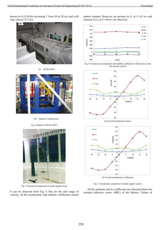
![coefficient of yaw and side force are negative, whereas the sign
of pitching moment is positive. For β sweep test; the model
strut assembly remained rested on tunnel turntable and rotated
at -20o
to +20o
range with 50
increments. As more attention is
given for defining the problem description than the flow
conditions. Hence, this technical note does not attempt to
predict the aerodynamic and stability coefficients for beta
sweep at different free stream velocities. A drastic increase in
side force is observed at α = 150
, Fig. 7(b). This figure also
shows a continuous increase in CL for defined range of and a
slight droppage in value of CD for β = ±100
. However, after β =
±100
, CD increases linearly till β = ±200
.
An asymmetric pattern is observed in overall trends of pitch
and yaw moment, Fig. 8(a). Same thing is reflected in
corresponding coefficient plots as well i.e. mC vs and nC vs
plots, respectively. However, general behavior is more
sinusoidal for the plot of nC vs . Fig. 8(c). Value of mC first
increases till for β = 50
but a drastic decrease in its value is
observed till β = 150
, Fig. 8(b). But its magnitude is not
consistent with that of its value at β = 150
. Values of nC for .
±200
are almost constant but a sudden increase in its value is
found at β = 50
. Since the overall behavior of these two
stability coefficients is non-linear. Therefore, it is quite
difficult to comment on the overall slopes of mC and nC .
-5
15
35
55
75
95
115
-20 -15 -10 -5 0 5 10 15 20
Moment(N.m)
(degree)
Pitch Moment
Yaw Moment
(a) Plots of pitch and yaw moment due to sweep
0
0.2
0.4
0.6
0.8
1
1.2
-20 -15 -10 -5 0 5 10 15 20
Cm
β (degree)
(b) mC vs
-0.02
-0.015
-0.01
-0.005
0
0.005
0.01
0.015
0.02
0.025
-20 -15 -10 -5 0 5 10 15 20
Cn
β (degree)
(c) nC vs
Fig. 8 Stability characteristics of model support system
Sometimes, the aerodynamic force of the body alone is defined
as the difference between the aerodynamic force of the body
attached with the strut and results of strut alone testing.
However, this is not the true representation as there is always
some effect of the interference due to model support system as
well. For example, the complete analytical relationship of the
drag force is expressed as follows [8]:
ISBm DDDD (1)
Where, Dm, Ds and DI are drag of the body, strut and due to
interference effects respectively. Drag due to tare is usually
automatically subtracted in online calculations by the DARCS
and hence it is not account far in the above equation. DI would
take out any interference effects due to supports and can be
estimated in future by subtracting the model-on wind-on
condition from the model off-wind on condition. This is a
shortcut (not perfect) to avoid lengthy procedure involving
measurements with inverted model [20].
V. CONCLUSION
For measurements of aerodynamic and stability coefficients
of only model support system placed normal to the flow, a
method is used where both the struts are at same height and
attached through a thin wire. For defined range of velocity, all
the aerodynamic and stability coefficients remain almost
constant for α = 00
. Diamond shaped profile of the mains strut
acts as a symmetric airfoil, which result in significant
contribution towards the side force. For side force rest of the
forces and moments, the overall trend is not symmetric.
Specially, an oscillating behaviour is observed in the trend of
nC vs . Such effects of the measured aerodynamic and
stability characteristics caused by main strut and the pitch rod
are of considerable magnitude and should be excluded from the
test results of complete configuration. Although the presented
results of proposed experimental setup furnish some interesting
finding but its interference with the model deserved much more
attention.
259
Fourth International Conference on Aerospace Science & Engineering (ICASE 2015) Proceedings](https://image.slidesharecdn.com/conferenceproceedingsicase2015final1-160918062150/85/Conference-proceedings-268-320.jpg)
![ACKNOWLEDGMENT
The support of the Ministry of Science, Technology and
Innovation (MOSTI), Malaysia, under the grant 06-01-08-
SF0189 is gratefully acknowledged. Authors are thankful to
Dr. Fadhil Hasim and his team for providing the diamond
shaped strut for the experimental work.
REFERENCES
[1] D., Biermann, & W. H. Herrnstein, The interference between
struts in various combinations. NASA Report No. NASA-L-
468, 1933
[2] E. P., Jones, S. M., Townsend, Y., Guy, & T. E. McLaughlin,
Reduction of the wave drag of a blunt body by means of a
standoff spike. AIAA Aerosp. Sei. Meet., 38th, Reno, NV,
2000
[3] S. Feldman, Some shock tube experiments on the chemical
kinetics of air at high temperatures. Journal of Fluid
Mechanics, 3(03), 225-242, 1957.
[4] K. L., Mikkelsen, & D. F. Long, Refurbishment, Calibration,
and Initial Testing in the ASE Hypersonic Wind Tunnel. In
43rd AIAA Aerospace Sciences Meeting and Exhibit, 2005.
[5] M. H. Bertram, (1950). Investigation of the pressure-ratio
requirements of the Langley 11-inch hypersonic tunnel with a
variable-geometry diffuser, 1950.
[6] D., Biermann, & W. H. Herrnstein, The interference between
struts in various combinations. NASA Report No. NASA-L-
468, 1933
[7] V., Nguyen, Y., Drolet, & Watt, G. (1995, January).
Interference of various support strut configurations in wind
tunnel tests on a model submarine. In 33rd Aerospace
Sciences Meeting and Exhibit (p. 443).
[8] V.A, Tucker, "Measuring aerodynamic interference drag
between a bird body and the mounting strut of a drag
balance." The Journal of Experimental Biology 154.1 (1990):
439-461.
[9] R. C. Pankhurst, (1958). Wind-Tunnel Interference Due to
Model Supports. Aircraft Engineering and Aerospace
Technology, 30(2), 55-55.
[10] A.U., Haque, W. Asrar, A.A, Omar, E., Sulaeman and J.S,
Ali, "Assessment of Engine’s Power Budget for Hydrogen
Powered Hybrid Buoyant Aircraft", Journal of Propulsion
and Power Research (in press), 2015
[11] A.U., Haque, W. Asrar, A.A, Omar, E., Sulaeman and J.S,
Ali, "Aerostatic and Aerodynamic Modules of a Hybrid
Buoyant Aircraft: an Analytical Approach", IIUM
Engineering Journal, IIUM Engineering Journal, Vol 16, No.
1 (2015).
[12] A.U., Haque, W. Asrar, A.A, Omar, E., Sulaeman and J.S,
Ali, “Power-off static stability analysis of a clean
configuration of a hybrid buoyant aircraft”, 7th Ankara
Internatıonal aerospace conference, 11-13 September 2015 -
METU, Ankara Turkey.
[13] J. A., Weiberg, & K. W. Mort, Wind-tunnel tests of a series
of parachutes designed for controllable gliding flight.
National Aeronautics and Space Administration, 1967
[14] G. R.,Spedding, M.Rosén, & A. Hedenström, A family of
vortex wakes generated by a thrush nightingale in free flight
in a wind tunnel over its entire natural range of flight speeds.
Journal of Experimental Biology, 206(14), 2313-2344, 2013
[15] A. Cogotti, Ground effect simulation for full-scale cars in the
pininfarina wind tunnel (No. 950996). SAE Technical
Paper.1995
[16] B. Hetherington, and D. B. Sims-Williams, Support Strut
Interference Effects on Passenger and Racing Car Wind
Tunnel Models. No. 2006-01-0565. SAE Technical Paper,
2006.
[17] J., Rossow, J. N., Sacco, P. A., Askins, L. S., Bisbee and S.
M Smith, Wind-tunnel measurements of hazard posed by lift-
generated wakes. Journal of aircraft, 32(2), 278-284, 1995.
[18] F. Hasim, R. Rusyadi, W. I. Surya, W., Asrar, A. A.Omar, ,
J., Syed Mohamed Ali, & R. Kafafy, The IIUM low speed
wind tunnel. Proceedings of EnCon2008 2nd Engineering
Conference on Sustainable Engineering Infrastructures
Development & Management, December 18-19, 2008,
Kuching, Sarawak, Malaysia
[19] User’s Manual 6-Component External Balance for
International Islamic University Malaysia Wind Tunnel, S &
V Teknik Sdn. Bhd and Aero Engineering, 2015.
[20] J. Barlow, W. Rae, A. Pope, Low Speed Wind Tunnel
Testing, Jon Wiley & Sons, 1999.
260
Fourth International Conference on Aerospace Science & Engineering (ICASE 2015) Proceedings](https://image.slidesharecdn.com/conferenceproceedingsicase2015final1-160918062150/85/Conference-proceedings-269-320.jpg)
![Fairing Separation Dynamic Analysis Using
Analytical Approach
Muhammad Tanveer Iqbal
Institute of Space Technology
Islamabad, Pakistan
mrtanveeriqbal@gmail.com
Dr. Abdul Majid
Institute of Space Technology
Islamabad, Pakistan
majid363@yahoo.com
Abstract— Fairing is the upper portion of launch vehicle,
usually made in two halves. It is used to protect the satellite from
loadings (thermal, aerodynamic and acoustic) of harsh
environment during ascent. Separation of fairing at particular
altitude is most critical part of launch vehicle flight which
dictates the success or failure of the whole mission.
This paper presents the designing of spring for separation
system of fairing using 1dof dynamic equations. Material
properties of base ring and spring are considered and integrated
in dynamic system of equations. These equations are modeled
and evaluated. Effects on separation time due to variations in
spring stiffness and compressed length are analyzed. After
analysis , best spring parameters are selected on the basis of
fairing separation requirements. Developed analytical method is
also validated through professional fairing separation software.
Keywords—satellite launch vehicle; fairing jettison; heat
shield; dynamic analysis; analytical approach; separation springs
I. INTRODUCTION
Fairing is designed to shield the satellite from acoustic,
aerodynamic and especially thermal loads. To minimize these
loadings inside the fairing, honeycomb and carbon fiber
sandwich structure is frequently employed. Separation of
fairing is typically done at altitude where free molecular heat
flux is less than 1135W/m2
to avoid damages to satellite [1-3].
Bending load and dynamic pressure are not considered for
fairing separation as their utmost values are achieved prior in
the flight [4].
Successful mission is heavily depends on fairing separation.
Many missions were failed just due to no or late separation of
fairing. In the March 4, 2011, Glory climate satellite launched
by Taurus launch vehicle was failed to achieve specific orbital
altitude due to failure of fairing separation and collapsed back
to earth [5].
Two halves of fairing are separated by using pyro-bolts and
gas/spring thrusters. In the given case, spring thrusters are
selected for designing jettison mechanism. Two main
considerations for designing separation mechanism are that the
magnitude of force produced by spring system must be enough
to separate the fairing's halves in given time at very high
acceleration and after separation, there should be no collision
of opened halves with the launch vehicle [6]. Both are directly
related to spring stiffness. If spring stiffness is low, sufficient
force would not be produced to open the fairing halves in given
time. The high spring stiffness will produce the high angular
velocity in fairing halves and cause its collision with launch
vehicle. Therefore, optimized value of stiffness must be
evaluated.
In this paper, along with stiffness, other design parameters
of spring used in fairing jettison mechanism are also evaluated.
For this purpose, analytical equations for rotational dynamics
are derived using laws of motion. Then using Range-Kutta
method, these equations are solved, simulated and analyzed.
Acquired results are validated through professional software
used for fairing separation calculations..
II. FAIRING SEPARATION MECHANISM
Jettison is started by lateral separation mechanism that
unlocks the fairing bottom from launch vehicle. Then pyro-
bolts of longitudinal separation mechanism are exploded that
separate both halves of fairing, followed force is released by
compressed springs which rotate the halves about hinges. After
reaching certain angle, fairing starts free fall rotation about its
center of gravity. Fairing and hinge structures under
consideration are illustrated in Fig. 1(a) and 1(b).
Fig. 1(a): Fairing structure
261
Fourth International Conference on Aerospace Science & Engineering (ICASE 2015) Proceedings](https://image.slidesharecdn.com/conferenceproceedingsicase2015final1-160918062150/85/Conference-proceedings-270-320.jpg)
![Fig. 1(b): Fairing model along with spring mechanism and hinge structure
III. FAIRING SEPARATION DYNAMICS
Dynamic equations are derived for 1-DOF system. For
analytical derivation, fairing is considered as rigid body.
During separation, hinge point's linear movement is neglected.
Frame moves with constant linear acceleration fixed on launch
vehicle, is taken as reference [7]. Pitch angle of launch vehicle
is taken as zero. Free body diagram of left half of fairing before
fairing separation is illustrated in Fig. 2. Free body diagram of
left half of fairing during separation is shown in Fig. 3.
Fig. 3: Free body diagram of left half of fairing before separation
Fig. 4: Free body diagram of left half of fairing during separation
For left half of fairing, summation of all the moments about
the hinge point is given by:
(1)
After re-arranging (1);
(2)
Where, 'Izz ' is the moment of inertia of left half about
hinge. 'Fs ' is the magnitude of force applied by all springs. 'ds'
is the moment arm of spring force 'Fs '. 'Mfair' is the mass of
fairing half. 'a' is the linear acceleration applied on the fairing
due to instantaneous thrust of launch vehicle, which is
considered as constant during separation. ' ' is the angle of
rotation of fairing half. 'Fs' is calculated using equation given
below.
(3)
Where, 'K' is stiffness of one spring. 'Xtot' is the total
compressed length of a spring. 'Ns' is the number of springs. In
given case, 2 springs are considered in separation mechanism.
'Xdef' is the instantaneous uncompressed length of spring during
separation and it is found using cosine law of triangle given by,
(4)
Equations (1) to (4) are coupled through ' '. These inter-
linked dynamic equations are solved by using Range-Kutta
method. Same is used for dynamic solution of right half of
fairing with trivial modifications.
Theoretically, force exerted by the spring system 'Fs ' on the
base ring and the reaction force 'Fr ' generated by the ring on
the spring system is equal. But in practical, "action is not equal
to reaction" due to inelastic contact of two bodies [8-9]. Spring
impingement on the base ring causes the absorption of energy
in the ring. Amount of energy absorbed depend on the
materials of spring and ring. Thus reaction force produced by
ring will always be less than the spring force. Harder material
absorbs less energy and vice versa. Force loss factor 'e' is
considered to make analytical solution closer to real results.
Therefore 'Fr ' is used instead of 'Fs ' in equation (2).
(5)
Equations (1) and (2) are valid prior to fairing separation
from hinge. After fairing separation, analogous equations are
required to derive for motion of fairing about its center of
gravity.
IV. RESULTS AND DISCUSSION
Equations are implemented and solved in MATLAB.
Spring parameters including spring stiffness, spring material
and compressed length, are evaluated to satisfy given
separation requirements given in table 1.
262
Fourth International Conference on Aerospace Science & Engineering (ICASE 2015) Proceedings](https://image.slidesharecdn.com/conferenceproceedingsicase2015final1-160918062150/85/Conference-proceedings-271-320.jpg)
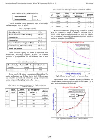
![Fig. 4: Reaction Force of Left Half of Fairing
Fairing's opening angle is presented in Fig. 8. At 0.78
sec, fairing achieved rotation of 70o
so it is released from
hinge, satisfying the requirements given in table 1.
Fig. 5: Opening Angle Theta of Left Half of Fairing
Fig. 9 presents the movement of fairing half in body
frame. Red curve shows the cg variation of fairing's half
during separation.
Fig. 6: Fairing's half Movement during Separation
V. CONCLUSION
Results show that designed analytical approach for fairing
separation dynamic analysis is fairly close to professional
software approach. Inclusion of material properties of spring
and base ring made results more comparable. Among various
springs of different stiffness and compressed lengths, best one
(having stiffness of 100,000 N/m and compressed length of
0.08m) is chosen on the basis of given fairing separation
parameters. 3dof and 6dof systems will be considered; modeled
and simulated in future that will provide complete dynamics of
fairing separation along all axes.
ACKNOWLEDGMENT
We would also like to show our gratitude to Dr. Imran
Afzal for providing insight and expertise that greatly assisted
the research.
REFERENCES
[1] Steven J. Isakowitz, Joshua B. Hopkins, Joseph P. Hopkins Jr.,
“International Reference Guide to Space Launch Systems,” 4th ed.,
AIAA, pp. 341, 2004.
[2] “Soyuz User's Manual,” Ariane Space, vol 2 rev. 0 ,March 2012.
[3] “Atlas Launch System Mission Planner's Guide, Atlas V
Addendum(AVMPG),” International Launch Services, pp. 2-7, Dec.
1999.
[4] Antonio Pagano, “Global Launcher Trajectory Optimization for Lunar
Base Settlement,” Delft University of Technology, May 2010.
[5] spacenews.com,‘Orbitals-glory-launch-failure-review-nears-conclusion’,
2011. [Online]. Available: http://spacenews.com/orbitals-glory-launch-
failure-review-nears-conclusion/. [Accessed: Aug. 9, 2015].
[6] Choong-Seok Oh, Byung-Chan Sun, Yong-Kyu Park and Woong-Rae
Roh, “Payload Fairing Separation Analysis Using Constraint Force
Equation,” International Conference on Control, Automation and
Systems, Gyeonggi-do, Korea, Oct. 27-30, 2010.
[7] Raymond H. Schuett, Bruce A. Appleby, Jack D. Martin, “Dynamic
Load Analysis of Space Vehicle System ,Launch and Exit Phase,”
General Dynamics Convair Division, Report No. GDC-DDE66-012,
June 1966.
Fairing's half
separated from
hinge
Path of CG
[9] en.wikipedia.org, 'Inelastic Collision', 2015. [Online]. Available:
https://en.wikipedia.org/wiki/Inelastic_Collision. [Accessed: Aug. 8,
2015].
[8] W. Bauer, G.D. Westfall, “Physics for Scientists and Engineers,” 3rd
ed., McGraw Hill, 2008.
264
Fourth International Conference on Aerospace Science & Engineering (ICASE 2015) Proceedings](https://image.slidesharecdn.com/conferenceproceedingsicase2015final1-160918062150/85/Conference-proceedings-273-320.jpg)
![Abstract— In this paper, a robust attitude control scheme for
satellite launch vehicle (SLV) is presented that is based on inverse
dynamics control augmented by sliding mode neural network
compensator. In this proposed scheme, the inverse dynamics
control acts as the primary control agent that computes the
control moment required to not only stabilize the launch vehicle
but also to implement the steering commands obtained from
guidance scheme. This control action is derived solely by the
inversion of launch vehicle dynamics; therefore, it is vulnerable to
errors resulting from the uncertainties, simplifying assumptions,
nonlinearities and various local and environmental disturbances
all of which cannot be accurately modeled. This problem is
addressed by the secondary control agent of the proposed control
scheme i.e. a sliding mode neural network compensator. This
nonlinear compensator is independent of the system dynamics and
therefore ensures stability against the un-modeled dynamics and
the disturbances acting on the launch vehicle. Along with this
hybrid control architecture, a guidance scheme is also developed
that reshapes the reference attitude profile on the basis of any
deviation from the desired trajectory of the launch vehicle so that
the desired orbit is reached. Lyapunov stability criterion is
incorporated in the control loop to guarantee system stability and
the efficacy of guidance and control scheme is verified on a six
degree of freedom simulation model developed exclusively in
Matlab/Simulink® using reference data for a four stage launch
vehicle. In these simulations, the launch vehicle is subjected to
various severe combinations of disturbances and parametric
variations and the control system successfully compensates all the
disturbances and efficiently tracks the desired attitude profile and
attains the targeted orbital parameters.
Keywords—Launch Vehicle Control, Dynamic Inversion,
Inverse Dynamic Control, Guidance and Control, Sliding Mode
Neural Network Compensator
NOMENCLATURE
m = Mass of vehicle
α= Angle-of-Attack
β= Side slip angle
δ= Deflection angle
J= Moment of inertia
ω = Angular rate
g = Gravitational acceleration
P = Thrust force
xr = Dist. from nose to nozzle center of gravity
xd = Dist. from nose to vehicle center of pressure
zr = Dist. from central line of vehicle body to parallel
central line of thrust pipe
xz = Dist. from nose to vehicle center of gravity
V = Air stream velocity of vehicle
C = Side force
L= Lift force
D = Drag force
φ= Pitch angle
ψ = Yaw angle
γ = Roll angle
θ = Flight Path Angle
𝜗 = Local flight path angle
σ = Heading angle
I. INTRODUCTION
The access to space in a reliable and cost effective way is a
critical requirement these days. This ability depends largely on
the performance of the guidance and control system of the
launch vehicle. The classical controllers for the ascent phase of
SLV depend heavily on the accuracy of its dynamic modeling
in order to perform as anticipated. Because, it may not satisfy
the stability and performance requirements if the SLV is
outside of its desired trajectory envelop. But, due to the various
uncertainties, nonlinearities and disturbances acting on the
system, the dynamics of SLV cannot be precisely modeled.
Therefore, the controller needs to have the ability to perform
even with inaccurate dynamic model. The controller of a
launch vehicle has to satisfy three often contradictory
requirements that are to stabilize the vehicle, reduce trajectory
deviations by efficiently implementing the steering commands
from guidance scheme and to minimize the angle of attack in
the high dynamic pressure region to avoid structural overload.
During the last few years, a lot of work has been reported in
the field of adaptive and nonlinear control of launch vehicle [1]
[2] [3] [4] [5]. Such techniques have the adaptability to adjust
their output in accordance with the varying dynamics of the
system while retaining the desired performance and stability.
Similarly, various techniques have been devised to enhance the
robustness of the inverse dynamic controller [6] [7] against
modeling uncertainties.
Launch Vehicle Control based on Dynamic
Inversion with Sliding Mode Neural Network
augmentation
Saqib Alam
SUPARCO, Pakistan
e-mail: alam.saqib@gmail.com
Syed Minhaj un Nabi Jafri
SUPARCO, Pakistan
e-mail: jafri_minhaj@yahoo.com
265
Fourth International Conference on Aerospace Science & Engineering (ICASE 2015) Proceedings](https://image.slidesharecdn.com/conferenceproceedingsicase2015final1-160918062150/85/Conference-proceedings-274-320.jpg)
![This research is aimed at demonstration of the simplicity
and effectiveness of inverse dynamic controller when it is aided
with a sliding mode neural network compensator in developing
the autopilot of SLV. The advantage of using this architecture
is that the primary control produces just enough control
moment that is required for vehicle stabilization and trajectory
following resulting in a simplified and efficient control law.
Whereas all the additional factors are taken care of by the
secondary control, hence ensuring robustness and adaptability.
The weights of the sliding mode neural network are tuned
adaptively in synchronization with the changing environment.
In order to inject a satellite in a desired orbit, an external
guidance loop is also required alongside the inner control loop
to provide the steering commands to the controller on the basis
of trajectory deviations that may occur due to environmental
and local disturbances. A simplified guidance scheme is
proposed here for successful accomplishment of orbital
parameters.
The paper is organized as follows. Section II illustrates the
mathematical modeling of SLV. Section III describes the
design of inverse dynamic control with sliding mode neural
network compensator for attitude control of SLV along with
the guidance loop. The simulation results are presented in
Section IV and Section V provides the concluding remarks.
II. DYNAMIC MODELING OF SLV
To analyze ascent flight trajectory, 6DOF simulation model
is developed in Simulink MATLAB in which the data of four
stage SLV is incorporated. The symbols definition of SLV is
depicted in Fig.1.
Fig. 1 Symbol’s definitions
Table I depicts the four stage data used to simulate the
trajectory of SLV.[1]
TABLE I. LAUNCH VEHICLE DATA
Parameters 1st
stage 2nd
stage 3rd
stage 4th
stage
Liftoff Mass (ton) 31.34 9.31 2.87 0.91
Fuel Mass (ton) 18.76 5.55 1.72 0.54
Thrust (kN) 593 262 94 30
Mass Flow rate
(kg/s)
265 103 37 13
Burn Time (s) 70.7 53.8 46.9 46.9
Stage Dia. (m) 1.3 1.0 0.7 0.5
The launch vehicle experiences various aerodynamic forces
and moments during its flight that act as disturbances and cause
trajectory deviations. In order to simulate these effects,
trajectory of 500 km orbit is considered with injection velocity
of 7612 m/s2
, DATCOM is used to compute aerodynamic
coefficients, mass flow rate and thrust are considered as
constant. The equations of motion are formulated considering
the rigid body dynamics, and are given as follows [2]:
sin cos 4 cos cosmV mg P D (1)
cos 4 sin cos
2 cos
mV mg P
P L
(2)
sin sin 4 sin
cos2 C
mV mg P
P
(3)
2
( )y z y zdx m kr
x
x x x
J Jm qS lPz
J VJ J
(4)
2
( ) ( )
2 ( )
dy m kz x d z
y x z
y y y
R z
y
m qS lJ J C x x
J J VJ
P x x
J
(5)
2
( ) ( )
2 ( )
x y d z dz m k
z y x
z z z
R z
z
J J L x x m qS l
J J VJ
P x x
J
(6)
Where,
III. DESIGN OF IDSNN CONTROL
For Launch vehicle, the proposed control architecture
266
Fourth International Conference on Aerospace Science & Engineering (ICASE 2015) Proceedings](https://image.slidesharecdn.com/conferenceproceedingsicase2015final1-160918062150/85/Conference-proceedings-275-320.jpg)
![consists of feed-forward term based on Inverse Dynamics of
SLV and feedback term in which sliding mode based neural
network compensator is employed.
A. Problem formulation
In order to apply dynamic inversion to on the attitude
dynamics of launch vehicle, it is assumed that the inertial rates
, ,p q r are equivalent to body rates , , neglecting the
effect of earth rotation. Therefore, the dynamic equations 4-6
can be written as:
(7)
Where, , , , , , , represent aerodynamic
moments, damping moment and control moment respectively.
B. Inverse Dynamic Control
The dynamic inversion methodology to formulate control
input diu requires two steps. The first step is the state and
input transformation to convert nonlinearities of the system
dynamics into its linear time invariant form:
z az bv (8)
The second step is the designing of the control
input v using linear control methodology. To achieve stable
tracking control, three variables of interest i.e.
( , , )diy are chosen as output variables. Transform
system to get the form as shown in Equ.8, Output vector is
differentiated twice to get input vector [8]:
di di di diy M N u (9)
Where,
T
diy ,
0 0 ( ) 0 0
0 0 0 ( ) 0
0 0 0 0 0
diM
0 0
0 0
0 0
diN
and diu
The desired input to the system can be written as:
1
( )di di di diu N M v
(10)
Where,
( )dI dIy v v v v (11)
To design the linear controller to control the output states
( , , )diy , the linear controller is written as:
( ) ( )
( ) ( )
( ) ( )
d d d p d
DI d d d p d
d d d p d
v k k
v v k k
v k k
(12)
C. Feedback term based on Sliding mode Neural Network
In practice, it seems to be impossible to model the exact
dynamics of the system. Since the dynamic inversion control
explicitly utilizes the modeled dynamics, it is assumed
that 0 ,aero
0damp
and 0con
represent aerodynamic, damping and
control moment of the nominal model respectively. The
difference in actual and nominal model is represented by
term for which the moments can be written as:
0 0
0
, ,aero aero aero damp damp damp
con con con
(13)
By substituting these values, Equ. 7 can be written as:
0 0
0 0 0
0 0 0
( , )
( , , )
( , , )
damp con damp con
aero damp con aero damp con
aero damp con aero damp con
f
f
f
(14)
In order to estimate the function ( , )damp con
f , for roll and
( , , )aero damp con
f for pitch and yaw, adaptive Sliding mode
Neural Network compensator (SNN) is proposed [9]. By
employing this, the control deflection computed by the
proposed controller is written as:
ˆ(.)diu f (15)
Radial Basis Neural Network compensator is designed on
the basis of sliding surface and the surface depends on error
and its rate. RBF networks are adaptively used to approximate
the uncertain f.
( )T
i if w h s
267
Fourth International Conference on Aerospace Science & Engineering (ICASE 2015) Proceedings](https://image.slidesharecdn.com/conferenceproceedingsicase2015final1-160918062150/85/Conference-proceedings-276-320.jpg)
![Where h(s) is the Gaussian function of neural network based
on sliding surface.
2
2
exp , 1,2,...5.
2
i
i
i
s c
h s i
(16)
Fig. 2 SNN structure
The sliding surface is defined as:[8]
*S C e e (17)
Let the nonlinear system is defined as:
( , )x f x x gu dt
We know that
s ce e
ds e ce x x ce (18)
ˆ ( )dx fx gu dt ce ksign s
The control input can be written as:
1 ˆ ( )du x fx dt ce ksign s
g
ˆ( ) ( ) ( )s f x f x dt ksign s
( ) ( )s f x dt ksign s (19)
Where
ˆ ˆ( ) ( ) ( )T T T
f f f w h s w h s w h s
Lyapunov function is defined as:
21 1
2 2
T
L s w w (20)
The derivation is written as:
T
L ss w w
ˆ( ( ) ) ( ( ))T
L w sh s w s dt ksign s (21)
Where ε is approximation error of neural network and γ is a
positive coefficient. The stability Criteria is defined as:
0LL
The adaptive law is selected as
1
ˆ ( )w sh s
Now we can write:
( ( )) ( )L s dt ksign s s dt k s (22)
Since approximation error is sufficiently small and
k dt
We get
0L
D. External Guidance loop:
In order to achieve the desired orbital parameters, an
external guidance loop is incorporated in the autopilot of SLV.
The guidance scheme performs the online reshaping of the
reference attitude profiles in the exo-atmospheric phase. It
computes deviations (Δx, Δy, Δz) from the intended trajectory
and on the basis of these deviations, it formulates the new
reference attitude angles accordingly. The controller in turn
tracks the updated reference profiles to attain the desired orbit.
dx x x (23)
dy y y (24)
dz z z (25)
1
tan
y
x
(26)
1
tan
z
x
(27)
d ref (28)
d ref (29)
The complete block diagram of the proposed control
algorithm with external guidance loop is depicted below:
268
Fourth International Conference on Aerospace Science & Engineering (ICASE 2015) Proceedings](https://image.slidesharecdn.com/conferenceproceedingsicase2015final1-160918062150/85/Conference-proceedings-277-320.jpg)
![Fig. 3 Guidance & Control architecture
IV. SIMULATION RESULTS
The performance evaluation of the proposed control
architecture was carried out on a six degree of freedom
simulation software developed in MATLAB Simulink. The
simulation result of pitch channel for the first 30 seconds of
flight including the pitch over phase under nominal flight
conditions is shown in Fig. 4.
Fig. 4 Pitch over Attitude profile with Compensator
It can be seen from Fig. 4 that the proposed controller is
efficiently tracking the reference pitch angle profile. The
robustness analysis against parametric variation of the control
scheme is carried out by the incorporation of 30% random
variation in mass properties of the SLV.
Fig. 5 Attitude profile without Compensator with Uncertainty
Fig. 6 Attitude profile with Compensator with Uncertainty
0 5 10 15 20 25 30
-0.8
-0.6
-0.4
-0.2
0
0.2
0.4
0.6
Time [Sec]
Deflection[Deg]
Without compensator
With compensator
Fig. 7 Comparison of Commands with Uncertainty
Fig. 5-7 show the comparison of controller performance
with and without the sliding mode neural network compensator
and their resultant outputs under parametric variations. It can
be seen that the hybrid control structure is immune to modeling
269
Fourth International Conference on Aerospace Science & Engineering (ICASE 2015) Proceedings](https://image.slidesharecdn.com/conferenceproceedingsicase2015final1-160918062150/85/Conference-proceedings-278-320.jpg)
![uncertainties.
The effectiveness of the proposed guidance scheme with
online trajectory reshaping is depicted in Fig. 8 that shows the
error in orbital attitude with and without guidance under
parametric variations. The guided SLV accurately attains the
desired orbit.
Fig. 8 Injection Altitude with uncertainties
Fig. 9 shows the pitch profile for the whole mission from
lift-off to orbit injection including online attitude reshaping
from guidance scheme to attain the desired orbital parameters.
0 100 200 300 400 500 600
-50
0
50
100
Time [sec]
PitchAngle[deg/sec]
Actual
Reshaping
Reference
Fig. 9 Pitch profile with uncertainties
V. CONCLUSION
An adaptive and robust control strategy for SLV autopilot
is presented in this paper that is based on inverse dynamic
control aided with a sliding mode neural network compensator.
Lyapunov stability criterion is utilized to ensure the stability of
the control algorithm. The simulation results prove that the
proposed controller not only guarantees stability but also
efficiently tacks the reference attitude profile and the steering
commands from the guidance loop even under parametric
variations. The guidance scheme performs the online reshaping
in the exo-atmospheric phase of flight in case of deviations
from the intended trajectory to meet the desired orbital
parameters accurately.
REFERENCES
[1] Uzair Ansari. "Hybrid Genetic Algorithm fuzzy rule based guidance and
control for launch vehicle", 2011 11th International Conference on
Intelligent Systems Design and Applications, 11/2011
[2] Ansari, Uzair, Saqib Alam, and Syed Minhaj un Nabi Jafri. "Trajectory
optimization and adaptive fuzzy based Launch Vehicle attitude control",
2012 20th Mediterranean Conference on Control & Automation (MED),
2012.
[3] Filho, W. C. L., "Application of Adaptive Control Sounding Rocket
Attitude", Proceedings of International Conference on Intelligent
Autonomous Control in Aerospace, Beijing, China, (1995).
[4] Zhihua Qu, “Robust Control of Nonlinear Uncertain Systems” John Wiley
& Sons, Inc. 1998.
[5] Yuri Shtessel, James McDuffie, Mark Jackson, Charles Hall, Don Krupp,
Michael Gallaher, and N. Douglas Hendrix, "Sliding Mode Control of the
X33Vehicle in Launch and Re-entry Modes," AIAA98-4414, Proceedings
of AIAA Guidance, Navigation, and Control Conference, Boston, MA,
August 10-12, 1998
[6] Ito D, Ward DT and Valasek J. Robust dynamic inversion controller
design and analysis for the X-38. In: AIAA conference on guidance,
navigation and control, Canada, 6–9 August 2001, paper no. AIAA-2001-
4380.
[7] David B. Doman and Anhtuan D. Ngo “Dynamic Inversion Based
Adaptive/Reconfigurable Control of the X-33 on Ascent” Journal of
Guidance Control and Dynamics, 2002.
[8] Abhijit Das, Frank L. Lewis and Kamesh Subbarao (2011). Sliding Mode
Approach to Control Quadrotor Using Dynamic Inversion, Challenges
and Paradigms in Applied Robust Control, ISBN: 978-953-307-338-5.
[9] Feng G (1995), “A compensating scheme for robot tracking based on
neural networks”. Robot Auton Syst 15(3):199–206.
270
Fourth International Conference on Aerospace Science & Engineering (ICASE 2015) Proceedings](https://image.slidesharecdn.com/conferenceproceedingsicase2015final1-160918062150/85/Conference-proceedings-279-320.jpg)
![Design and Development of Low cost Motor Drive
for Hub Wheel based Electric Vehicles
Syed Wasif Ali Shah
SUPARCO-Karachi-Pakistan
wasif_iiee@yahoo.com
Muhammad Asim
SUPARCO-Karachi-Pakistan
m_asim2000@hotmail.com
Abstract—Robotic mobility platforms are serving a wide
range of civil, commercial, domestic and military applications.
This paper describes the design and development of low cost
motor drive, applicable for wide range of permanent magnet DC
(PMDC) motors for electric vehicles and especially for the hub
wheel motors as they exhibit a distinctive frequency behavior.
This controller comprises of 3 units: First, a logic unit providing
control signals; Second, a sensing unit for over current and
batteries protection: third, a high power switching unit for
driving motors. Though applicable to wide range of unmanned
ground vehicles (UGVs) but here it is implemented in a
differential drive autonomous UGV built on hub motor wheels
with a speed of 1.88 m/sec, endurance of 2 hours and payload
capacity of more than 100 kg. Features, performance and
development cost of the drive in comparison with the similar
commercially available drives is also discussed.
Keywords— Mobility platforms; UGV; Hub Wheel; Motor
Drive;
I. INTRODUCTION
Unmanned ground vehicles (UGVs) are the mobility platforms
that have enormous civil, commercial, military, domestic and
urban applications [1][2] ranging from rescue, surveillance,
reconnaissance, mine detection, fire fighting, material
handling, agriculture, handicapped assistance, border security,
special weapons and tactics (SWAT) robot, manipulation,
exploration, automation, transportation, handling in dangerous
environment and many others. UGVs may be based on
different propulsion systems like engine based, electric or
hybrid drive mechanism [3]. Similarly different applications
and features require different traction and locomotion systems
[4] depending upon the required speed, tracks, obstacle
traversing, energy efficiency, load bearing capacity,
mechanical and control complexity and many others. To meet
different applications and fulfill different tasks through UGVs,
varieties of motorized actuation systems are available and
applied; also different mechanical structures and their level of
complexity have different actuation systems [5].DC motors
amongst them are most widely used actuator in electric
vehicles due to their low cost, simple and economical control
and weight to performance ratio [6].Varieties of DC motor
drives are available having different options, ratings and
control interfaces [7][8][9]. The motor drive described here
has the ability to drive wide range of permanent magnet
brushed DC motors with power rating of up to 1.8 KW.
Particularly we have developed a UGV shown in fig: 1 with
the dimensions of 72 cm in length, 91 cm in width and 20 cm
in height, having weight of 90 kg and payload capacity of
more than 100 kg build on the Hub motorized wheels. This
UGV is primarily designed for autonomous transportation
with GPS navigation with maximum speed of 1.88 m/sec. The
UGV has the differential drive mechanism with zero turning
radius. The motor drive has shown the ability to smoothly
control the hub motor’s torque, rpm and direction. The
advantage of hub wheel motor in building the UGV is its
mechanical simplicity and installment, compactness giving
more room to other components, less complex structure of
motion transmission eliminating axels and drivelines, reduced
weight giving more efficiency and endurance and ability of
high torque at low rpm [10]. The implemented hub motor has
the following major parameters given in tab-1.
Table 1: Hub Motor Parameters
Parameter Value
Power 250W
Voltage 24 Vdc
RPM 120
Radius 6 in
Figure 1: The differential drive UGV build with Hub motorized wheels
271
Fourth International Conference on Aerospace Science & Engineering (ICASE 2015) Proceedings](https://image.slidesharecdn.com/conferenceproceedingsicase2015final1-160918062150/85/Conference-proceedings-280-320.jpg)


![Table 2: Costing of the motor drive.
Component Appromimate
Cost
Drive PCB $10
Drive Components $48
Development $7
Total $65
Table 3: Specifications of the motor drive
Specification value
Supply voltage 13V to 50V
Output Current (continuous) 160A
Output Current (surge) >400
Switching Frequency Upto 16 kHz (with 4 MOSFESTs)
Weight 100 g (without fan)
MOSFETs 16 (4 per leg)
On Resistance .0026 ohm max at 25C
Cooling
Through optional 40 CFM 12 volt
fan
Dimension (mm) 115(L)X80(W)X35(H)
Parameters and features of the drive are given in tab: 3. The
drive has competitive features and performance if compared
with similar commercially available PMDC motor drives
whose prices range from $200-$400 [7][8][9]. The drive is
thoroughly tested with different motors and loading conditions
for different applications. It conforms to the specifications
especially under harsh and open environment of robotic
mobility platforms for long durations. Different features can
also be added in this design with minimal marginal cost which
otherwise incurs heavy cost if procured.
V. CONCLUSION
The paper discussed the design and development of low cost
PMDC brushed motor drive. Particularly implemented in
differential drive UGV with heavy payload capacity, build
with hub motorized wheel showing distinctive frequency
response. The developed controller consists of three units:
logic unit, sensing unit and high switching power unit. The
drive can be driven virtually with any microcontroller and
other signal sources like PC and wirelessly with RC signals. It
senses the current being drawn and the battery voltage levels
and further can be enhanced to monitor other motor
parameters like temperature. Features and development cost of
the drive are also discussed and compared with similar drives
available commercially. The drive is very economical with
easy service and replacement.
VI. REFERENCES
[1] V. Sezer, C. Dikilita, Z. Ercan, H. Heceoglu, A.Buner, A.Apak,
M.Gokasan and A. Mugan “Conversion of a conventional electric
automobile into an unmanned ground vehicle (UGV)” IEEE
international conference on Mechatronics, pp. 564-569, (2012)
[2] A. Bouhraoua, N.Merah, M. Al-Dajani and M. Elshafi “Design and
development of an unmanned ground vehicle for security applications”
7th International symposium on mechatronics and its applications, pp.
1-6, (2010)
[3] LinoGuzzella, Antonio Sciarretta “Vehicle propulsion systems”
Introduction to Modeling and Optimization, 2nded.
[4] L Bruzzone and G. Quaglia “ Review Article: Locomotion systems for
ground mobile robots in unstructured environment” Mech:sci:, 3,49-62,
2012, www.mech-sci.net/3/49/2012/
[5] William Brown “Improving the electromechanical performance of Robot
Arms on Unmanned Ground Vehicles” GRRC Technical report 2010-01,
12/20/2009
[6] Nasser Hashemnia and Behzad Asaei“Comparative study of using
different electric motors in the electric vehicles” proceedings of the 2008
international conference on electrical machines, paper ID 1257.
[7] Roboteq, Inc., “Brushed DC motor controller”, Online:
http://roboteq.com, 2015.
[8] Robot Power. “Robot power products”, Online: http://robotpower.com,
2015.
[9] VEX Robotics. “Victor Motor Controller”. Online:
http://vexrobotics.com, 2015.
[10] Machine Design. “A look at the advantages of hub motors as well as
disadvantages”, Online: http://machinedesgin.com, 2015.
274
Fourth International Conference on Aerospace Science & Engineering (ICASE 2015) Proceedings](https://image.slidesharecdn.com/conferenceproceedingsicase2015final1-160918062150/85/Conference-proceedings-283-320.jpg)
![Preparation, Structure and Dielectric/Piezoelectric
Properties of BiScO3-PbTiO3-Pb(Mn1/3Nb2/3)O3 High
Temperature Piezoelectric Ceramics
Shahid Karim1
, Jinting Tan1
, Adil Murtaza2
, Shahid Sultan2
, Khalida Kareem2
, Muhammad Nouman Shaikh3
1
Electronic Material research laboratory & International Center of dielectric research, School of Electronics and Information
Engineering, Xi’an Jiaotong University, Xi’an 710049, China
2
School of Sciences, Frontier Institute of Science and Technology, MOE Key Laboratory for Nonequilibrium Synthesis and
Modulation of Condensed Matter, State Key Laboratory for Mechanical Behaviour of Materials, Xi’an Jiaotong University, Xi’an
710049, China
3
Xi’an Jiaotong University, Xi’an 710049, China
Abstract—With the rapid growth of science and technology,
more piezoelectric devices should be used in high-temperature
environment. Commercially using PZT piezoelectric ceramics
have a low curie temperature (<150°C). So the present study is
focused on synthesis and characterization of high Curie
temperature piezoelectric ceramics. As a kind of excellent high
Curie temperature piezoelectric ceramics BiScO3-PbTiO3 (BS-
PT) system at MPB reveals high Curie temperature piezoelectric
properties. Pb(Mn1/3Nb2/3)O3-PbTiO3 (PMnN-PT) system
ceramics have excellent piezoelectric properties at MPB with low
Curie temperature (150°C). 0.1PMnN-BSPT ceramics show the
optimal piezoelectric properties with d33=200pC/N, kp=0.40,
Tc=338°C, Ec=22.75kV/cm and Pr=21.85µC/cm2
. The 0.05PMnN-
BSPT ceramics indicate the optimal piezoelectric properties with
d33=250pC/N, kp=0.54, Tc=373°C, Ec=14.63kV/cm and
Pr=11.51µC/cm2
. Also 0.06PMnN-BSPT system with 64mol.% PT
indicates the optimal piezoelectric properties with d33=210pC/N,
kp=0.49, Tc=328°C, Ec=20.21kV/cm and Pr=8.35µC/cm2
. So the
introduction of PMnN reduces the curie temperature; 10mol.%
of PMnN indicates the “hard” behavior as a function of reducing
the piezoelectric properties; 6mol.% of PMnN indicates the
“soft” behavior with increasing the piezoelectric properties.
Index Terms—Morphotropic phase boundary (MPB), Curie
temperature, Piezoelectric Properties, High-temperature
piezoelectric ceramics, Binary system ceramics
I. INTRODUCTION
Piezoelectric ceramic is a kind of important functional
ceramic material, which can realize the conversion between
mechanical energy and electric energy which are widely used
in manufacturing, micro displacement transducer and
ultrasonic generator etc. With the development of science and
technology, a lot of electrical and electronic equipment which
are used in high temperature piezoelectric devices increased
the demand. Study on the high temperature, with excellent
piezoelectric properties of piezoelectric ceramic materials
have become a hot research topic of functional ceramics
industry. The commercial applications of lead zirconate
titanate (PZT) in piezoelectric ceramics range of Curie
temperature system is 250-380°C, and the temperature is
limited to 150°C or less, which is far less than high
temperature piezoelectric devices. For a long time, a lot of
piezoelectric crystal materials due to the use of high
temperature and excellent piezoelectric properties have
become an important part of high temperature piezoelectric
applications [4]. Therefore high electromechanical power
applications requires such ceramics with better electrical
properties such as the piezoelectric strain constant (d33>200
pC/N), low dielectric loss (tanδ) mechanical quality factor
(Qm>1000), planar electromechanical coupling factor (kp> 0.5)
[1-3]. Lead niobate (PbNb2O6) tungsten bronze structure was
first discovered, it has tetragonal tungsten bronze structure [5].
This system has large anisotropy piezoelectric coefficient,
quality factor, low and high Curie temperature (570°C) is not
easy to depolarization, therefore particularly suitable for the
manufacture of high temperature transducer. But pure lead
niobate piezoelectric activity difference exists, the
electromechanical coupling coefficient is low, and is not easy
to sinter, and its high temperature ferroelectric phase at room
temperature is not stable. There is irregular grain growth and
phase transformation during sintering and cooling process
caused by the large volume change, so it is difficult to prepare
the excellent performance of the pure lead niobate
piezoelectric ceramic materials [6]. Through the substitution
of bismuth layer structure piezoelectric ceramic modification
can improve its piezoelectric activity. Korzunova [5] in the
Bi3TiNbO9 system, using Ti4+
, Ta6+
or W6+
instead of B in the
Nb5+
, using K+
to replace Bi3+
, the piezoelectric constant 5
pC/N is increased to 24 pC/N.
II. EXPERIMENTAL PROCEDURE
Mixture grade (>99.9% purity) powders of Bi2O3, PbO,
Sc2O3, TiO2, MnCO3, and Nb2O5 were used to make xPbTiO3-
(0.9-x)BiScO3-(0.05 to 0.15)Pb(Mn1/3Nb2/3)O3, (x=0.64). The
mixture of MnCO3 and Nb2O5 was ball-milled in a
polyethylene jar for 4h by high purity tetragonal zirconia
polycrystalline (3Y-TZP) ball media (Tosoh Co., Tokyo,
Japan). The mixed slurry was dehydrated and condensed for
calcination and phase formation at 800°C, 850°C and 900°C
for 5h. The Mn1/3Nb2/3O2 phase was confirmed by X-ray
diffractometer (XRD) after calcination, to obtain fine particles
the calcined piece was ball milled again for 4 h. After
preparation of Mn1/3Nb2/3O2 powder, PbO, Bi2O3, Sc2O3, and
275
Fourth International Conference on Aerospace Science & Engineering (ICASE 2015) Proceedings](https://image.slidesharecdn.com/conferenceproceedingsicase2015final1-160918062150/85/Conference-proceedings-284-320.jpg)
![TiO2 were mixed with it and ball milled to make final
compositions. Pellets (12.7x3mm) were compressed under a
pressure of 100 MPa by using a hydraulic press. Pressureless
sintering was performed in a high purity alumina crucible at
1100°C, 1150°C and 1200°C for 2h. To prevent from reaction
with alumina crucible, the specimens were put on a Pt-foil
inside crucible. After sintering, apparent densities were
measured by the Archimedes method.
Electrode formation was done by sputtering silver on the
lapped surfaces of pallets. By applying dc field of 3.5 kV/mm
for 10 min, electroded specimens were poled at 120°C in
silicone oil. Dielectric properties were acquired by measuring
the capacitance and loss using LCR meter (HP model 4284).
To determine Curie temperature, capacitance measurements
were completed as a function of temperature in an automated
temperature controlled furnace linked with a computer for data
acquirement. The piezoelectric coefficient (d33) was noted from
one-day aged samples by using Berlincourt-d33 meter.
Electromechanical coupling factor (kp) and mechanical quality
factor (Qm) were obtained by using an impedance analyzer
(Model HP4194) built on the IEEE standards [12]. Each
experimental step is given in Fig. 1.
Make the composition of
Mn1/3Nb2/3O2 by the
molecular weight of
MnCO3, and Nb2O5
Calcinate it at
1000'C for 5 hours
Mix the powders of Mn1/3Nb2/
3O2, PbO, Bi2O3, Sc2O3 and
TiO2 and take six compositions of
5%, 6%, 8%, 10%, 12% and 15%
Calcinate each sample
at different temperature
800'C, 850'C and 900'C
respectively
Blend the powders by
mixing with PVA+
Water and take the
specific grain size of
powders to make pallets
Sintered each
sample at different
temperatures
1150'C, and 1200'C
Make the pallets
shape smooth and
then measure the
apparent densities of
each sample
silver was pasted for
the electrode
formation
The electroded
specimens were poled in
silicone oil at 120
o
C by
applying a d.c. field of
3.5 kV/mm for 10 min
piezoelectric coefficient d33
was recorded using a
Berlincourt d33 meter,
dielectric properties were
obtained using an LCR meter
Ball milled,4h
Ball milled,4h
XRD
XRD
Fig. 1. Flow chart of experiment
III. RESULTS AND DISCUSSIONS
A. Sintering behavior and microstructures
Fig. 2, shows Powder XRD for the samples 5, 6, 8, 10, 12
and 15% of PMnN calcined at 800°C, 850°C and 900°C. It is
clearly shown at 8% of PMnN the XRD pattern is smooth.
Also it is studied that all the samples show tetragonal and
rhombohedral phases. Fig. 3, shows sintered XRD for the
samples 5, 6, 8, 10, 12 and 15% PMnN which are sintered at
1150°C. There is clearly shown at all doping percentage of
PMnN the XRD pattern is smooth. Also it is seen from the
angle 44 to 46 at the peak of 200 of all the samples show
tetragonal and rhombohedral phases. Fig. 4, shows sintered
XRD for the samples 5, 6, 8, 10, 12 and 15% PMnN which are
sintered at 1200°C. There is clearly shown at all doping
percentage of PMnN the XRD pattern is smooth. Also it can be
seen from the angle 44 to 46 at 200 peak, all samples show
tetragonal and rhombohedral phases.
Fig. 2. Powder X-ray Diffraction Analysis of Samples
Fig. 3. XRD of the samples of x=5, 6, 8, 10, 12, 15% respectively
sintered at 1150°C
Fig. 4. XRD of the samples of x=5, 6, 8, 10, 12, 15% respectively
sintered at 1200°C
The microstructures of the composites were studied by
Scanning electron microscope (SEM). The SEM micrographs
of the samples (a) 5%; (b) 6%; (c) 8%; (d) 10%; (e) 12% and
(f) 15% of PMnN sintered at 1150°C for 2h are shown in Fig.
5. They showed different microstructures distinctly; grain size
of each sample is (a)3.6; (b)2.8; (c)3; (d)3.2; (e)3.7; and (f)2; in
micrometers respectively and grain boundaries of sample
(c)8% are more clear and significant. The SEM micrographs of
the samples 6% of PMnN sintered at (a) 1100°C; (b) 1150°C
and (c) 1200°C respectively for 2h are shown in Fig. 6. They
showed different microstructures distinctly; grain size of each
276
Fourth International Conference on Aerospace Science & Engineering (ICASE 2015) Proceedings](https://image.slidesharecdn.com/conferenceproceedingsicase2015final1-160918062150/85/Conference-proceedings-285-320.jpg)

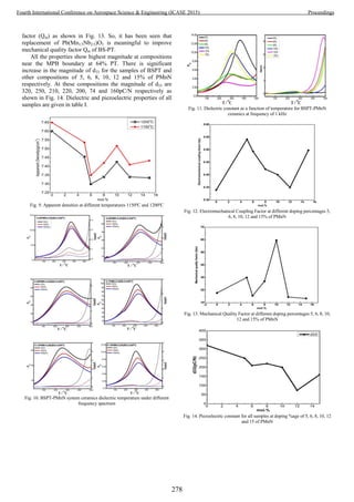
![TABLE I. Dielectric and Piezoelectric Properties with Curie temperature
Systems d33 (pC/N) Tc (°C) kp Qm εr εmax
5% 250 373 0.54 30 1018 12820
6% 210 328 0.49 15.6 761 4874
8% 220 302 0.42 27.06 1149 5104
10% 200 338 0.40 59.60 931 9809
12% 74 286 0.35 14.5 764 3169
15% 160 326 0.50 13.38 927 10248
E. Ferroelectric Properties
Polarization is saturated PS at high electric fields and there
is no more motion of the domain walls. Area of the hysteresis
curve shows heat density generated in the material at one
cycle. It is clearly seen that the 10% of PMnN has high
polarization value as well as electric field as shown in Fig. 15.
If the residual magnetization is high when magnetic
intensity will zero, it means that material have strong value of
magnetization. If the value of residual magnetization is less, it
means it will not retain the magnetization for long time after
removing the magnetic intensity. The results of remanent
polarization and coercive field were given in tab. II.
When the electric field began to decrease because of the
crystal stress domain deviate from the direction of
polarization, the electric field is reduced to zero, still remain in
the polarization direction of ferroelectric domains, thus the
macro reflects the remnant polarization, so that the material is
polarized. When the electric field is reversed, the remnant
polarization disappears, so the coercive field can be regarded
as the minimum field strength of the domain.
Fig. 15. Polarization of all compositions with 5, 6, 8, 10, 12 and 15% of PMnN
TABLE II. Remanent Polarization and Coercive Field
System
Remanent Polarization
(Pr/µC/cm2
)
Coercive Field
(kV/cm)
5% 11.50 14.63
6% 8.36 20.21
8% 10.99 11.03
10% 21.85 22.75
12% 9.42 13.81
15% 9.82 19.78
IV. EFFECTS OF ANNEALING ON DIELECTRIC AND
PIEZOELECTRIC PROPERTIES OF BSPT-PMNN CERAMICS
Microstructure of ceramics sturdily depends on annealing
process and it defines the ceramic’s physical performance.
Density, homogeneity and grains size in the annealing steps are
significant to attain the preferred electrical properties [7]. It
will influence the crystallographic phase, microstructure and
electrical properties of the resultant thin films [8-10]. The
temperatures of pre-annealing and annealing were determined
by the results of the thermal analysis and XRD, respectively.
A. SEM Analysis After Annealing
The microstructure of the compositions after annealed was
investigated by SEM. The SEM graphs of the samples (a) 5%;
(b) 6%; (c) 8%; (d) 10%; (e) 12% and (f) 15% of PMnN
respectively annealed at 800°C for 2h are shown in Fig. 16.
SEM microstructures of the annealed body are not showing any
second phase. They have clearly displayed different
microstructures; grain size of each sample is (a)3.2; (b)2.8;
(c)7.2; (d)4; (e)2.2; and (f)2; in micrometers respectively and
grain boundaries of sample (c)8% are more clear and
significant. They showed various microstructures clearly with
annealed temperature of sample 8% of PMnN, grain size was
increased and grain boundaries of sample (a) and (d) are also
clear and significant. Nevertheless the microstructures of the
every composition are uniform.
B. Piezoelectric Properties After Annealing
The piezoelectric coefficient d33 was noted from one-day
aged samples by a Berlincourt d33 meter (IAAS ZJ-2, Beijing,
China). All the properties displayed highest magnitude of
compositions near MPB boundary that is 0.64PT. As compared
to BS-PT ceramic, there is noticeable decrease in the
magnitude of d33 [11]. Also there is noticeable increase in the
magnitude of d33 after annealing for the samples of BSPT and
other compositions of 5, 6 and 12% of PMnN respectively. At
these compositions the magnitude of d33 are 490, 320, 270,
230, 210, 120 and 165pC/N respectively as shown in Fig. 17.
The electromechanical coupling factor kp was measured
using an impedance analyzer (Model HP 4194) based on the
IEEE standards [12]. Electromechanical resonance properties
determined after annealed at 800°C for 2h from the admittance
spectra at low field ac drive are shown in Fig. 18, as a function
of PMnN composition. Near the MPB boundary, 64% PT the
sample of 10 and 12% of PMnN there is a bit increase in kp
factor, at 5 and 15% there is decrease in kp factor as clearly
shown in Fig. 18.
The factor Qm was calculated by using an impedance
analyzer. As a consequence of the higher amount of coercive
field and Curie temperature of BS-PT, this composition is
predictable as high power piezoelectric material, if we can
increase the value of quality factor Qm. Near the MPB
boundary, 64% PT the sample of 5, 10, 12 and 15% of PMnN
there is clearly increment in quality factor (Qm) as shown in
Fig. 19. So, the replacement of Pb(Mn1/3Nb2/3)O3 is effective to
improve the mechanical quality factor Qm of BS-PT system.
279
Fourth International Conference on Aerospace Science & Engineering (ICASE 2015) Proceedings](https://image.slidesharecdn.com/conferenceproceedingsicase2015final1-160918062150/85/Conference-proceedings-288-320.jpg)
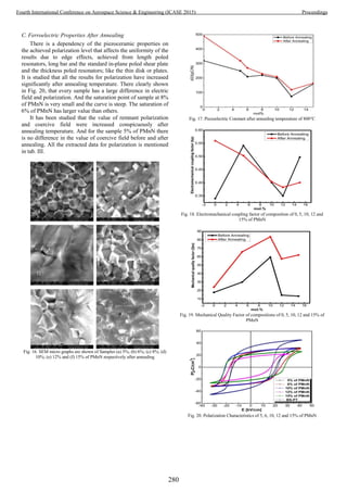
![TABLE III. Remnant Polarization and Coercive Field after annealing
System
Remnant Polarization
(Pr/µC/cm2
)
Coercive Field
(kV/cm)
5% 23.30 -14.66
6% 24.93 -17.02
10% 25.63 -20.55
12% 17.35 -17.01
15% 21.29 -21.17
BSPT 33.98 -17.33
V. CONCLUSION
BSPT-PMnN dense ceramic samples were prepared by the
columbite pre-production process. XRD results show that, at
the appropriate sintering temperatures, two systems were
obtained with pure perovskite structure. In systems of
0.05PMnN-BSPT, 0.06PMnN-BSPT, 0.08PMnN-BSPT,
0.1PMnN-BSPT, 0.12PMnN-BSPT and 0.15PMnN-BSPT
when the content of PT is 64% is the tetragonal-phase
existence of morphotropic phase boundary region. SEM
images show that the ceramic sample’s grain sizes are in
uniform distribution at the appropriate sintering temperatures,
the grain size is about 1µm. When the content of PMnN is
low, the PMnN-BSPT system shows the characteristics of
typical relaxor ferroelectrics, with the increase of PMnN
content, gradually transition from ferroelectric relaxor to
normal ferroelectrics. Due to low content of PMnN, PMnN-
BSPT system does not show obvious relaxation
characteristics. With the increase of PMnN content, the
remnant polarization Pr, first increased and then decreased.
The coercive field system gradually increases with the
increase of PMnN content. The piezoelectric properties of the
optimal compositions of 0.1PMnN-BS-PT and 0.05PMnN-
BSPT system in the morphotropic phase boundary region are:
d33=250pC/N, kp =0.54 and the Curie temperature of
Tc=373°C. The piezoelectric properties of the optimal
composition of 0.05PMnN-0.95BSPT system in the
morphotropic phase boundary region are better than other
optimal compositions.
After annealing at 800°C for 2h, the resident strain can be
quited and the order degree of lattice may be higher than that
without annealing process. Annealing process may affect the
domain size and domain switch, domain size will be larger
after annealing process. The value of Qm increase evidently
after annealing process.
ACKNOWLEDGMENT
I would like to thank my father and teachers for their kind
and humble guidance from the very start to the end of the paper
writing. I would not have accomplished this without their
constant support and feedback; they made it a thorough
learning and pleasant experience for me. I admire the guidance
and assistance provided by research associates and fellows.
REFERENCES
[1] Ueha, S., “Ultrasonic motors: theory and applications,” Vol. 29.
1993: Oxford University Press, USA.
[2] Chen, H., “The influence of Pb(Mg1/3Nb2/3)O3 content on the
piezoelectric and dielectric properties of PMNN-PZT system
near the MPB. in Applications of Ferroelectrics,” 2002. ISAF
2002. Proceedings of the 13th IEEE International Symposium
on. 2002. IEEE.
[3] DU, H. l., “Effect of sintering temperature and composition on
microstructure and properties of PMS-PZT ceramics,”
Transactions of Nonferrous Metals Society of China, Vol. 16:
pp.165-169, 2006.
[4] Weis, R. and T. Gaylord, “Lithium niobate: summary of
physical properties and crystal structure,” Applied Physics A,
Vol. 37(4), pp. 191-203, 1985.
[5] Korzunova, L. V., and L. A. Shebanov, “New perovskite-like
high temperature ferroelectrics,” Ferroelectrics, vol. 93.1 pp.
111-115, 1989.
[6] B. Frit and J. P. Mercurio, “The crystal chemistry and dielectric
properties of the Aurivillius family of complex bismuth oxides
with perovskite-like layered structures,” Journal of Alloys and
Compounds, vol. 188, pp. 27-35, 1992.
[7] M. Ghasemifard, “Dielectric, piezoelectric and electrical study
of 0.65PMN-0.20PZT-0.15PT relaxor ceramic,” The European
Physical Journal Applied Physics, Vol. 54, No. 2 , pp. 20701-
20707, 2011.
[8] Laughlin, Brian, Jon Ihlefeld, and Jon‐Paul Maria, “Preparation
of sputtered (Bax, Sr1−x)TiO3 thin films directly on copper,”
Journal of the American Ceramic Society, vol. 88.9.pp 2652-
2654 2005.
[9] Malic, Barbara, “Processing and dielectric characterization of
Ba0.3 Sr0.7 TiO3 thin films on alumina substrates,” Journal of the
European Ceramic Society 27, pp. 2945-2948, 2007.
[10] Tahan, Danielle M., Ahmad Safari, and Lisa C. Klein.,
“Preparation and characterization of BaxSr1‐x, TiO3 thin films
by a Sol‐Gel technique,” Journal of the American Ceramic
Society, vol. 79.6, pp.1593-1598, 1996.
[11] Chen, Jun, “Temperature dependence of piezoelectric properties
of high-TC Bi(Mg1/2Ti1/2)O3-PbTiO3,” Journal of Applied
Physics, vol. 106.3 pp.034109-034109, 2009.
[12] IEEE “Standard on piezoelectricity,” IEEE Standard 176-1978
(IEEE, New York, 1978).
281
Fourth International Conference on Aerospace Science & Engineering (ICASE 2015) Proceedings](https://image.slidesharecdn.com/conferenceproceedingsicase2015final1-160918062150/85/Conference-proceedings-290-320.jpg)
![A Comprehensive Study on QoS for Mobile
Ad Hoc Network
Abdur Rasheed Irfan Nazeer Fayyaz Khalid
Department of Computer Science Department of Computer Science Department of Computer Science
University of Gujrat University of Gujrat University of Gujrat
Gujrat, Pakistan Gujrat, Pakistan Gujrat, Pakistan
abdur.rasheed@live.com irfan6200@yahoo.com fayyazrao@yahoo.com
ABSTACT----A Mobile Ad Hoc Network (MANET) is a
collection of nodes which has no centralized
administration and without the assistant of base station.
All the nodes have equal rights and have their own
resources in MANET. QoS is a challenging issue now-a-
days due to bandwidth constraints and dynamic
topology in MANET. A lot of work done on supporting
on QoS in internet and other networks but most of them
is not suitable for MANET. Most of work is about the
QoS routing, QoS Mac and resource reservation, there
is a little work discuss on QoS models and its routing
protocols. In this article, we review the QoS models and
share some knowledge about QoS routing protocols and
other related work on QoS in MANET. The purpose of
this article is to give the appropriate knowledge about
QoS for MANET at the same platform.
Keywords: QoS, Mobile Ad Hoc Networks
I. Introduction
Wireless network has become a popular network
now-a-days. Wireless communication has been
making our life easy and comfortable. Wireless
communication has been categorized into two
primary models; one is traditional wireless
network in which a fix infrastructure is used to
communicate between one hop to another. In
conventional wireless network, much of the
nodes are mobiles and connected with the help of
fixed backbone nodes using wireless
medium(radio waves). In this type wireless
network a base station is used for
communication. But in some situation (i.e. storm
disaster, battle field) there is no fix infrastructure
is used. Then we used a specific type of network
which is called “Mobile Ad Hoc Network”. A
mobile ad hoc network (MANET) [1][2], is a
dynamic wireless system in which all nodes are
mobile and nodes can move in any direction,
independent of each other. According to [3],
Mobile Ad hoc Networks are class of networks
whose contains characteristics is,
Physical characteristics –As MANET is
a wireless network in which nodes can
create link in any time, bandwidth and
Delay due to the nodes are mobile.
Organization – As mobile nodes are
distributed so resource estimation is not
predefined in MANET
Dynamic Topology – As the nodes have
dynamic topology so it has no fixed
architecture.
MANET is the combination of different mobiles
nodes which does not have any server, router or
access points for communication. It has low cast
wireless network and easy for deployment.
MANET is used in different situations in our life
i.e., Military operations, Rescue search
operations, communication between mobiles
vehicles in smart transportation, mobiles phones,
laptops and smart watches etc. As shown in Fig.1
MANET provides a flexible and seamless access to
internet. Due to in increasing popularity in MANET,
282
Fourth International Conference on Aerospace Science & Engineering (ICASE 2015) Proceedings](https://image.slidesharecdn.com/conferenceproceedingsicase2015final1-160918062150/85/Conference-proceedings-291-320.jpg)
![QoS has become the main task of research in
MANET. QoS is a challenging issue now-a-days due
to dynamic topology and bandwidth constraints. A lot
of work is done on supporting on QoS for internet
and other networks but most of them are not suitable
for MANET. Due to autonomous wireless network,
MANET has its own protocols.
In this literature, we discuss QoS for MANET
includes QoS models and also discuss some
important protocols in MANET. There are many
researches on QoS on the internet. Due to this, it is
difficult to get appropriate knowledge on QoS in a
specific location. This paper provides a
comprehensive knowledge on QoS models for
MANET and some QoS routing protocols. In first
part, we shall discuss some QoS models which are
specified an architecture in which we discuss some
services that can be used in MANET. In second part,
we discuss some QoS protocols for MANET. These
protocol are divided in the based on route discovery,
metrics and network architecture. Then we gives a
comparison of these protocols on the bases on route
discovery, metrics and network architecture.
II. QoS models and MANETs
QoS model defines the architecture which provides a
platform to different services; which is used in
networks. QoS models use different situations like
dynamic topology etc. QoS model consider the
exiting internet architecture for MANET.
In this section, we explain the different QoS models
especially DiffServ and one of the newly proposed
QoS Model FQMM.
A. IntServ and MANETs
The idea of IntServ[4] is taken from the wired
network architecture and B-ISDN i.e. have the virtual
circuit mechanism. Virtual connection is maintains
through signaling protocol RSVP (Resource
Reservation Protocol)[4].RSVP is very important
protocol in all QoS support routers. IntServ provides
two types of services; one is Guaranteed [5] Service
and the Other is Controlled Load Service [6]. Here
some pros and cons of IntServ mentioned below:
a) Scalability
IntServ provides per-flow granularity so when state
information is increases the number of lows is also
increased. This requires storing a lot storage capacity
and processing is increases, it results a problem that's
called scalability problem of IntServ. The scalability
problem is very less in current MANETs because
there is less number of users, less bandwidth and
small size of network. On the other Hand, in future
the use of MANETs is increasing rapidly and the size
and speed of the MANETs increases so the
Scalability problem is also increased with time so
IntServ is not suitable in MANETs.
b) Signaling
Signaling protocols like Resource Reservation
protocol have three steps; connection maintenance,
connection tear-down and connection establishment.
Corson[7] assumes and then suggest that a larger
number of links is given to the network to control
overhead .For MANETs with link capacities, the
overheads of connection maintenance and dynamic
topology usually a large for connection establishing
so that RSVP signaling protocol is not suitable in
MANETs.
c) Router mechanisms
IntServ is required a large number of routers so that
all router have packet scheduler, classifier, admission
control routine and RSVP that's why it is undesired
able in MANETs.
B. DiffServ and MANETs
Like ATM and IntServ, the tenet of DiffServ [8] is
used a relative-priority scheme to soften the hard
requirements of hard QoS models. DiffServ is
specially designed for the deficiencies of IntServ and
RSVP model like scalability problems in internet
backbone [9]. DiffServ is defined limited classes for
overcome this problem of IntServ. Much kind of
283
Fourth International Conference on Aerospace Science & Engineering (ICASE 2015) Proceedings](https://image.slidesharecdn.com/conferenceproceedingsicase2015final1-160918062150/85/Conference-proceedings-292-320.jpg)
![services are supported in DiffServ model which are
following [10]:
a) Premium Service
Premium Service is considered to give the end-to-end
bandwidth services, low jitter, low loss and low delay
[11].
b) Assured Service
Assured service is used to provide better reliability
for application. Other, it is more qualitative service
than quantitative and easy to implement.
c) Olympic Service
Three types of services are provided in Olympic
services which are Gold, Silver and Bronze with
decreasing quality [9].
Premium service is not suitable in MANETs because
it implementation in dynamic environment is not
possible. DiffServ is considered a defined solution to
MANETS QoS model because it provides Assured
Service and it is lightweight in inner router which is
suitable to MANETs. Because of this, DiffServ is
designed for wired networks and have some
problems in MANETs which are follows
DiffServ is not sure in to the boundary nodes for
this; it requires a lot of storage capacity.
DiffServ provides a Service Level Agreement
(SLA) which implementation is not possible in
MANETs. SLA is an agreement between
customer and the internet service Provider (ISP)
to receive Differentiated Services. SLA obeys
the partial or whole traffic rules [12]; but in
MANETs, it is not possible to negotiate the
traffic rules.
C. Flexible Quality of Service Model (FQMM)
and MANETs
FQMM is the first QoS model which is preferred in
MANETs. FQMM is proposed in [13] and it tries to
take advantage from IntServ and DiffServ models
both. FQMM is designed for average size MANETs
which comprises less than 50 nodes using at non-
hierarchical topology. However, FQMM is a hybrid
approach because it has combined features from
IntServ and DiffServ. In FQMM infrastructure, it has
types of Nodes like DiffServ which follows:
Ingress Node
Interior Node
Egress Node
Ingress node is a source node which is a mobile node.
Interior node is the intermediate node that sends the
data of other mobile nodes. Egress node is the node
which is received data and it is the destination node.
Note that the role of Ingress node is changing due to
change in its position and network traffic. Resource
determination and allocation is done to the various
mobile nodes by using provisioning in FQMM.
Provisioning is at top level and based on utilization of
the network in present internet. Provisioning is used
to realize ideal per-flow by RSVP in IntServ and is
used in DiffServ as per-class by human agents rather
than RSVP or other. But on the other hand, FQMM
introduced a hybrid scheme as per-flow as well as per
class. Traffic with highest priority is given per-flow
provisioning while other priority is based on per-
classes. Although it is the first efficient model in
MANETs but there is further need to study that how
sessions is entertained as per-flow due to bandwidth
constraints in MANETs.
III. QoS Aware-Routing Protocols
In this section, we discuss some QoS aware routing
protocols. After this, we discuss their functionality
and then see their comparisons with each other with
different aspects. The QoS Aware-Routing Protocols
are follows:
A. Optimized link stat routing Protocol
OLSR [14, 15] is a proactive routing protocols and
the idea of OLSR is given by IETF MANET[3]
working group. OLSR is the further study of Link
stat routing protocols. The idea of OLSR is based on
MPRs (Multi Point Relays).Every MPR have two
hops distance which is the part of communicating
nodes. If a node has no MPR then it cannot transfer
data further. Consider that MPR have larger distance
than a node which is not a MPR then we may miss
some good quality links and that's reason, it is
difficult to achieve a good quality of service in
OLSR.
284
Fourth International Conference on Aerospace Science & Engineering (ICASE 2015) Proceedings](https://image.slidesharecdn.com/conferenceproceedingsicase2015final1-160918062150/85/Conference-proceedings-293-320.jpg)
![B. Predictive Location Based QoS Routing Protocol
PLBQR [16] is a proactive routing protocol which is
used in MANET.PLBQR is totally based on location
prediction of a node a particular instant in ad hoc
wireless networks. Location prediction is used to find
the geographical location of a node at particular
instant 'tf' when the receiver node picks a packet in
future. The value of 'tf' is calculated by calculating
delay in communication. No resources are reserved
during the propagation from source to destination but
QOS is controlled. This QoS routing protocol is
helped the nodes to update location prediction and
delay during communication.
C. Ticket Based QoS Routing Protocol
Ticket Based QoS Routing protocol [17] is a reactive
protocol which is used in MANETs. The basic idea
of Ticket Based QoS Routing protocols is to use
tickets to find the best path which may delay
constrained or bandwidth constrained. This protocols
is used two types of tickets, one is yellow ticket and
the other is green. The purpose of yellow tickets is to
find the best path with delay/bandwidth constraints.
The other green ticket purpose is to find the low cost
route. The source node has a lot the number of tickets
to establish a QOS aware route. The tickets may be
less or more it depends on the route constraints to
find the best path. The Drawback of this routing
protocol is that the neighbor nodes incorporated to
each other with resource estimation that’s why it
requires more memory. When a route is established
to the destination node acknowledged even resource
reservation is established.
D. Ad Hoc QoS on Demand Routing
The idea of AQOR [18] protocol is to find the best
route which is fulfills the constraints of end to end
delay with specific bandwidth. In route discovery, the
route request is sends to nearby node and attaches the
constraints with the packet and if both nodes satisfy
then this request is rebroadcasted to the next hop with
some expiry time. If the node is not received the
reply in given time then entry will be deleted. If the
nodes do not want to delete path the only
intermediate nodes will reply. Once the route is found
then resource reservation is takes place on the found
route. If the route is deleted the new route request is
sent.
E. Adaptive QoS Routing Algorithm
ADQR [19] is a reactive protocol. Adaptive QoS
Routing algorithm protocol is used to establish a
route between two nodes which have longer life time.
In these protocols, the route breakage and route
creation is bases on signal power. Bandwidth is
considered to the lower layer. Route maintenance
contains two ways. One is pre-routing and the other
is rerouting. Pre-routing is used when the value of the
threshold is greater than signal power and rerouting is
used when the signal power is very low. For example
of this protocol is; if a node want to communicate
with other node then it sends a RREQ packet to
nearby node and then intermediate node attached his
address to this packet and forward to the next. If the
packet is reached to the exact destination then
destination node checked that the signal power.
Signal power ensures that the route is enough or it
disjoints with others .QoS_Reserve packet is sent to
the current route back and QoS Acknowledgment is
sent to the source. [3]
F. Trigger-based Distributed-QoS Routing
Protocol
TDR [20] is a reactive protocol which is a location
based protocol. In this protocol every host node
contains two types of databases. One is for local
neighbor and other is activity based. Hosts are passed
out the mobility and location information and the
neighbor nodes is stored the power level in their local
database. Activity-based data base is stored the every
session routing information and updated in every
session. Route discovery is done through the
neighboring power level and compared this with
threshold time. Route maintenance is done like
ADQR protocol [3].
G. Bandwidth Estimation QoS Routing Protocol
BEQR [21] is a reactive protocol which is inspired by
AODV routing protocol [23].The main objective of
this protocol is to give soft QoS for service with the
bandwidth constraint. In this two schemes is used one
is Feedback scheme and the other is Admission
285
Fourth International Conference on Aerospace Science & Engineering (ICASE 2015) Proceedings](https://image.slidesharecdn.com/conferenceproceedingsicase2015final1-160918062150/85/Conference-proceedings-294-320.jpg)
![scheme. In Feedback scheme is used for updating
constraints when a node have no bandwidth its own.
Admission Scheme is used for route discovery with
satisfied bandwidth constraints. In this protocol
bandwidth is calculated with ratio of free and busy
times. Resource reservation is not considered. It is
design for soft QoS not hard.
H. Core Extraction Distributed Ad hoc Routing
Protocol
CEDAR [23, 3] was proposed by R. Siva Kumar
[23].CEDAR is a QoS aware routing protocol and it
is a hybrid routing protocol. In this protocol nodes
are selected as Core node and they are responsible for
route maintenance, computation and QoS providing
by using distributed algorithm. Link state information
depends on network state whether it is dynamic or
stable.
Route computation is on-demand based and Cedar
contain following three features which is very
important:
1. Destination location discovery and
establishing the core path to destination
2. Core nodes provides the stable and short
path between source to destination and also
a core path guideline
3. If the path is break then it re-established as
well as typology changes.
CEDAR considers that the resource is reserved.
[3]The route maintenance in CEDAR is done as
source initiated route maintenance or dynamic route
maintenance.
I. INSIGNIA
INSIGIA [24] is a hybrid protocol which is proposed
for adaptive services in ad-hoc networks. Adaptive
services entertains that types of services which
requires minimum QoS guarantee (like minimum
bandwidth) and it varies when resources is sufficient.
INSIGNIA in-band signaling is the very important
component which is entertained fast reservation to
deliver the adaptive services[25].Routing module is
responsible for finding routes between nodes and
sends the packets to the next node(intermediate).In
any time of transmission when topology is changed it
is established a new path. Every data packet has a
optimal QoS field and admission control module is
responsible for resource reservation; it is refreshed
periodically. If an application is used to want
minimum bandwidth then it bandwidth indicator is
"MIN", if the application is used to want maximum
bandwidth then indicator indicates "MAX".
J. Forward Algorithm
FA [26] belongs to the on-demand routing protocols
which is used on demand algorithms with bandwidth
as QoS constraints parameter. FA is the modified
version of AODV [22] is used for route discovery
and some additional information is attached before
sending to the next hope. During route discovery, the
value of local maxima is calculated and forward [27].
FA is used in many other reactive protocols like
TORA [28] and DSR [29] for route discovery. The
Route maintenance is managed by using old routes in
it.
286
Fourth International Conference on Aerospace Science & Engineering (ICASE 2015) Proceedings](https://image.slidesharecdn.com/conferenceproceedingsicase2015final1-160918062150/85/Conference-proceedings-295-320.jpg)
![IV. Comparison of QoS Aware-Routing Protocols
A comparison of QoS aware-routing protocols is given below:
Routing Protocols QoS Support Redundant Route Route Maintenance Route Breakage
Prediction
Network
Architecture
Route Discovery
OLSR X X X Hierarchical Proactive
PLBQR X X Location
Prediction
Proactive
Ticket Based X Flat Reactive
AQOR X X Flat Reactive
ADQR Flat Reactive
TDR X Location Based Reactive
BEQR X X X Flat Reactive
CEDAR X X Hierarchical Hybrid
INGIGNIA X X Flat Reactive
FA X X Flat Reactive
Conclusion
In first part of this paper, we have described three
QoS Models (IntServ, DiffServ and FQMM).All
three models are suitable for different situations. All
three have some pros and cons; but FQMM is a
flexible QoS model for MANETs. To our knowledge,
FQMM was the first such QoS model proposed for
MANETs. It provides a hybrid provisioning scheme
and a relative and adaptive traffic profile. In second
part of this paper, we described some important QoS
aware-routing protocols in ad hoc wireless networks
which is an active research now-a-days. In this paper,
we discussed some characteristics of the QoS routing
protocols and compare the characteristics of these
protocols in the form of table. The aim of this review
is to give an appropriate knowledge on QoS for
MANETs at the single paper.
References
[1] Loay Abusalah, Ashfaq Khokhar, and Mohsen Guizani “A
Survey of Secure Mobile Ad Hoc Routing Protocols” IEEE
communications surveys & tutorials, VOL. 10, NO. 4, FOURTH
QUARTER, 2008, pp 78-93.
[2] Sunil Taneja and Ashwani Kush” A Survey of Routing
Protocols in Mobile Ad Hoc Networks”, International Journal of
Innovation, Management and Technology, Vol. 1, No. 3, August
2010.
[3] Lei Chen and Wendi B. Heinzelman, “A Survey of Routing
Protocols that Support QoS in Mobile Ad Hoc Networks”, IEEE
Network November/December 2007.
[4] R. Braden, D. Clark, and S. Shenker. Integrated Services in the
Internet architecture - an
Overview. IETF RFC1633, June 1994.
[5] S. Shenker, C. Partridge and R. Guerin “Specification of
Guaranteed Quality of service” RFC 2212 September 1997
[6] J. Wroclawski, “Specification of the Controlled-Load Network
Element Sevice ” RFC 2211, Sept.1997
[7] M.S. Corson. Issues in supporting quality of service in mobile
ad hoc networks. In IFIP 5th Int.Workshop on Quality of Service
(IWQOS'97),May 1997.
[8] S. Blake. An architecture for Di_erentiated Services. IETF
RFC2475, December 1998.
[9] Xipeng Xiao Nad Lionel M. Ni “Internet QoS: a big Picture,”
IEEE Network magazine , March 1999.
[10] Kui Wu and Janelle Harms “Quality of Services in Mobile Ad
Hoc Networks”
[11] K. Nichols, V. Jacobson, and L. Zhang. A two-bit
Di_erentiated Services architecture for the Internet. IETF
RFC2638, July 1999
[12] S. Blake, “An Architecture for Differentiated Services,” IETF
RFC 2475, December 1998.
[13] H. Xiao , W.K.G. Seah, A. Lo and K. C. Chua, “A flexible
Quality of Service Model for Mobile Ad hoc Networks” IEEE
VTC2000-spring . Tokyo, Japan May 2000.
[14] Y. Ge, T. Kunz, and L. Lamont, “Quality of Service Routing
in Ad-Hoc Networks Using OLSR,” Proc. 36th Hawaii Int’l. Conf.
Sys. Sci., Jan. 2003.
[15] P. Jacquet, P. Muhlethaler, A. Qayyum, A. Laouiti, L.
Viennot, T. Clauseen, "Optimized Link State Routing Protocol
draft-ietf-manet-olsr-05.txt", INTERNET-DRAFT, IETF MANET
Working Group.
[16] S.H.Shah and K.Nahrstedt, “Predictive Location- Based QoS
Routing in Mobile Ad Hoc Networks,” Proceedings of IEEE ICC
2002,vol.2, pp.1022-1027, May 2002
287
Fourth International Conference on Aerospace Science & Engineering (ICASE 2015) Proceedings](https://image.slidesharecdn.com/conferenceproceedingsicase2015final1-160918062150/85/Conference-proceedings-296-320.jpg)
![[17] S. Chen and K. Nahrstedt, “Distributed Quality-of-Service in
Ad Hoc Networks,” IEEE JSAC, vol. 17, no. 8, 1999.
[18] Q. Xue and A. Ganz, “Ad hoc QoS On-demand Routing
(AQOR) in Mobile Ad hoc Networks,” J. Parallel and Distrib.
Comp., vol. 62,no. 2, Feb.2003, pp. 154–65.
[19] Y. Hwang and P. Varshney, “An Adaptive QoS Routing
Protocol with Dispersity for Ad-hoc Networks,” Proc. 36th Hawaii
Int’l.Conf. Sys. Sci., Jan. 2003.
[20] S. De et al., “Trigger-Based Distributed QoS Routing in
Mobile Ad Hoc Networks,” ACM SIGMOBILE Mobile Comp.
and Commun.Rev., vol. 6, no. 3, July 2002, pp. 22–35.
[21] Lei Chen and Wendi B. Heinzelman, “QoS-Aware Routing
Based on Bandwidth Estimation for Mobile Ad Hoc Networks,.
IEEE Journal on Selected Areas in Communications,
23(3):561_572, March 2005.
[22] C. E. Perkins and E. M. Royer. “Ad-hoc On-Demand Distance
Vector Routing”, In Proceedings of the 2nd IEEE Workshop on
Mobile Computing Systems and Applications, pages 90_100, New
Orleans, LA, Feb. 1999
[23] R. Sivakumar, P. Sinha, and V. Bharghavan, “CEDAR: a core
extraction distributed ad hoc routing algorithm” IEEE Journal on
Selected Areas in Communication, Vol. 17, no. 8, pp 1454-65
August1999.
[24] X. Zhang, S.B Le, A. Gahng-Seop and A.T Campbell,
“INSIGNIA: an IP based quality of service framework for mobile
ad hoc networks.”Journal of Parallel and Distributed Computing,
Vol. 60, no. 4,pp. 374-406, April 2000.
[25] C.Siva Ram Murthy,B.S.Manoj, “Ad Hoc Wireless Networks
Architectures and Protocols” Prentice Hall Communications
Engineering and Emerging Technologies Series.
[26] Chenxi Zhu and M. Scott Corson. “QoS routing for mobile ad
hoc networks”. Technical report, Flarion Technologies,
Bedminster, New Jersey 07921, 2002.
[27] Philipp Becker, “QoS Routing Protocols for Mobile Ad-hoc
Networks – A Survey”, TU KL Technical Report 368/08, A
publication by University of Kaiserslautern
[28] V.D. Park and M.S. Corson, “A Highly Adaptive Distributed
Routing Algorithm for Mobile Wireless Networks”, Proceedings of
IEEE INFOCOM 1997, pp.1405-1413, April 1997.
[29] D.B.Johnson and D.A. Maltz, “Dynamic Source Routing in
Ad Hoc Wireless Networks”, Mobile Computing, Kluwer
Academic Publishers,vol.353,spp.153-181,1996.
288
Fourth International Conference on Aerospace Science & Engineering (ICASE 2015) Proceedings](https://image.slidesharecdn.com/conferenceproceedingsicase2015final1-160918062150/85/Conference-proceedings-297-320.jpg)
![Comparison of Maximum Likelihood Classification
Before and After Applying Weierstrass Transform
Muhammad Shoaib, Zaka Ur Rehman, Muhammad Qasim
Abstract— The aim of this paper is to use Maximum
Likelihood (ML) Classification on multispectral data by means of
qualitative and quantitative approaches. Maximum Likelihood is
a supervised classification algorithm which is based on the
Classical Bayes theorem. It makes use of a discriminant function
to assign pixel to the class with the highest likelihood. Class
means vector and covariance matrix are the key inputs to the
function and can be estimated from training pixels of a particular
class. As Maximum Likelihood need some assumptions before it
has to be applied on the data. In this paper we will compare the
results of Maximum Likelihood Classification (ML) before apply
the Weierstrass Transform and apply Weierstrass Transform
and will see the difference between the accuracy on training
pixels of high resolution Quickbird satellite image. Principle
Component analysis (PCA) is also used for dimension reduction
and also used to check the variation in bands. The results shows
that the separation between mean of the classes in the decision
space is to be the main factor that leads to the high classification
accuracy of Maximum Likelihood (ML) after using Weierstrass
Transform than without using it.
Index Terms— Maximum Likelihood Classificaion (ML),
Weierstrass Transform, Bayes Theorem, Supervised
Classification, Principle Component Analysis (PCA).
I. INTRODUCTION
Satellite images are widely used for various purposes and
with the advancement in Satellite technology every country
wants to solve their problem by using satellite images. Satellite
images can be used in various disciplines such as Metrology,
Environmental sciences, GIS, Geology, Geophysics,
Engineering and Construction, Defense and Intelligence and
the list goes on.
Satellite images contains maximum information about our
planet and main problem is that how can we retrieve the useful
information satellite images. Researchers can have several
problems such how to classify the land cover types, depth of
Aerosol particles in atmosphere, Forest Climates, Flood
predictions and many more. Researcher solve these problems
by analyzing the satellite images.
In this article our main aim is to classify the land cover
types by using Maximum Likelihood Classification algorithm.
First we classify land cover types without using Weierstrass
Transform (WT) and then we compare the results by applying
Weierstrass Transform (WT).
Maximum Likelihood (ML) is a supervised classification
method derived from the Bayes theorem, which states that the a
posteriori distribution P(i|θ), i.e., the probability that a pixel
with feature vector θ belongs to class i, is given by:
where P(θ|i), is the likelihood function, P(i) is the a priori
information, i.e., the probability that class i occurs in the study
area and P(θ) is the probability that is observed, which can be
written as:
where M is the number of classes. P(θ) is often treated as a
normalization constant to ensure ∑P(i|θ) sums to 1. Pixel x is
assigned to class i by the rule:
Each pixel is assigned to the class with the highest likelihood
or labeled as unclassified if the probability values are all
below a threshold set by the user [1].
Maximum Likelihood (ML) assumes that the data within a
given class i obeys a multivariate Gaussian distribution.
Frist we implement Maximum Likelihood (ML) classification
algorithm without checking the assumption of normality and
then we apply Maximum Likelihood (ML) classification after
using Weierstrass Transform on the image data and we have
seen that after applying Weierstrass Transform our data is
normally distributed. The accuracy after applying Weierstrass
Transform (WT) is increased because the distribution of the
data is normal because for ML classification data has to be
normal.
II. STUDY AREA
We use Quickbird satellite image for our analysis.
Quickbird is high-resolution commercial satellite which is
owned by DigitalGlobe and launched in 2001. Quickbird uses
Aerospace's Global Imaging System 2000 (BGIS 2000).The
Quickbird satellite collected panchromatic (black and white) at
61cm resolutin and multispectral imagery at 2.44-(at 450 km)
to 1.63-meter (at 300km) resolution, as orbit altitude is lowered
during the end of mission life [2].
The Quickbird satellite image which we use for our
analysis is sample image of Rome Italy with coordinates
with four bands which are
blue (450-520nm), green (520-600nm), red (630-690 nm) and
NIR (760-900 nm).
289
Fourth International Conference on Aerospace Science & Engineering (ICASE 2015) Proceedings](https://image.slidesharecdn.com/conferenceproceedingsicase2015final1-160918062150/85/Conference-proceedings-298-320.jpg)
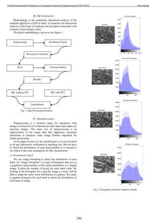
![In the figure 2 we can see that the distribution of each band
is not Gaussian and we know that for ML classification
algorithm the distribution of each has to be Gaussian. In this
case distribution of first three bands are positively skewed
while the histogram of band 4 is looks like Gaussian but not
exactly Gaussian. So as our aim is to check the accuracy of
classification before making data Gaussian and after making it
Gaussian. We use Weierstrass Transform to make the
distribution Gaussian.
B. Weirstrass Transform
As we have seen that distribution of our data is not follow
Gaussian distribution so make that Gaussian we have to use
transformation to make pixel values Gaussian.
Researchers uses various types of transformation to make
the data Gaussian. In this paper we use different type of
transformation called Weirstrass Transform.
The Weirstrass transformation, also known as the Gauss
transform, the Gauss Weirstrass transform and the Hille
transform, is intimately related to the solution of the heat
equation for one- dimensional flow. It is also a special case of
convolution-transform, yet it is considered a singular case of
convolution-transform theory developed by Hirschmann and
Widder [3].
The Weirstrass transformation F(x) of a function f(y)
defined as:
the convolution of f with the Gaussian function .
Instead of F(x) we also write W[f](x). Note that F(x) need not
exist for every real number x, because the defining integral
may fail to converge [3].
When Gaussian filter modifies the input signal by using
Gaussian function; this is known as Weierstrass
transformation.
We can write Gaussian function mathematically in 2D as
follow:
where ρ is the correlation between X and Y and where σ_x>0
and σ_y>0. In this case,
In the bivariate case, the first equivalent condition for
multivariate normality can be made less restrictive: it is
sufficient to verify that countably many distinct linear
combinations of X and Y are normal in order to conclude that
the vector [X Y]′ is bivariate normal.
Gaussian filtering is used to blur images and remove noise
and detail. Gaussian filter uses the above Gaussian function
which is given in equation 1.
After applying Gauss transform or Wierstrass transform we
can compare original false color composite (FCC) image with
transformed false color composite (FCC) image.
(a) original false color composite (FCC) image
(b) Transformed false color composite (FCC) image
Fig. 3.
In figure 3 we can see the clear difference between original
FCC image with transformed FCC image. After applying
transformation we can see that the transformed image is more
blur than original image.
291
Fourth International Conference on Aerospace Science & Engineering (ICASE 2015) Proceedings](https://image.slidesharecdn.com/conferenceproceedingsicase2015final1-160918062150/85/Conference-proceedings-300-320.jpg)
![In the above figure we can see that band 3(Red) and band
4(NIR) have same information so we have to neglect band 3
or band 4 from our analysis because they have same
information in the image for this purpose we will use
classification on three bands that are Blue, Green and NIR.
D. Training Samples
Training areas were established by choosing one or more
polygons for each class. Pixels fall within the training area
were taken to be the training pixels for a particular class. In
order to select a good training area for a class, the important
properties taken into consideration are its uniformity and how
well they represent the same class throughout the whole image
[4].
We use Stratified random sampling for selecting the
training pixels. A stratified random sample is a population
sample that requires the population to be divided into smaller
groups, called 'strata'. Random samples can be taken from each
stratum, or group.
V. RESULTS
Maximum Likelihood considered to be an most accurate
algorithm when we compare it to classical algorithm such as
parallelepiped classification algorithm. But as we know that
ML classification algorithm assumes that distribution of each
band has to be Gaussian. we had seen that our band's
distribution was not Gaussian so we make distribution
Gaussian by applying Gauss transform or Weirstrass transform.
Now we will check what is the effect on accuracy of
classification classes when the distribution is Gaussian and
when not Gaussian.
A. Classification Before Weirstrass Transform
The outcome of ML classification after assigning the
classes with suitable colors, is shown in Fig.5 (a): Grass
(green), Urban Area (blue), Roads(yellow), Soil (cyan), Trees
(red) and Unclassified (Black). The areas in terms of
percentage and square meters were also computed; the classes
with the largest area is Urban Area. In this case the distribution
of our data is not Gaussian and we can clearly see in the Fig.5.
(a) that some buildings are wrongly classified as Roads
because we are applying ML classification on non normal data.
Class Color Area in % Area in Meters²) Color
Unclassified: [Black] 6.44% (26,783.6400 Meters²)
Trees [Red] 14.20% (59,095.0800 Meters²)
Grass [Green] 13.63% (56,719.0800 Meters²)
Urban Area [Blue] 31.45% (130,868.2800 Meters²)
Roads [Yellow] 30.31% (126,133.9200 Meters²)
Soil [Cyan] 3.97% (16,532.6400 Meters²)
(a)
Class Color Area in % Area in Meters²) Color
Unclassified: [Black] 10.30% (42,851.1600 Meters²)
Trees [Red] 13.75% (57,232.0800 Meters²)
Grass [Green] 10.34% (43,005.2400 Meters²)
Urban Area [Blue] 44.79% (186,373.0800 Meters²)
Roads [Yellow] 19.39% (80,677.4400 Meters²)
Soil [Cyan] 1.44% (5,993.6400 Meters²)
(b)
Fig. 5. (a) Maximum Likelihood classification an original image, (b) Maximum Likelihood classification on transformed image
293
Fourth International Conference on Aerospace Science & Engineering (ICASE 2015) Proceedings](https://image.slidesharecdn.com/conferenceproceedingsicase2015final1-160918062150/85/Conference-proceedings-302-320.jpg)
![TABLE I. CONFUSION MATRIX OF ORIGINAL CLASSIFIED IMAGE
Class Color Trees Grass Urban Area Roads Soil Color
Unclassified [Black] 0.4 0.05 7.84 2.33 0
Trees [Red] 94.38 8.06 0.94 5.28 0
Grass [Green] 1.64 88.71 2.66 0.03 3.41
Urban Area [Blue] 0 1.06 70.71 1.19 2
Roads [Yellow 3.58 0 4.61 91.17 0
Soil [Cyan] 0 2.11 13.23 0 94.59
Total 100 100 100 100 100
Ground Truth (Percent)
Overall Accuracy = (18318/21394) = 85.62%
Kappa Coefficient = 0.8135
TABLE II. CONFUSION MATRIX OF TRANSFORMED CLASSIFIED IMAGE
Class Color Trees Grass Urban Area Roads Soil Color
Unclassified [Black] 0.85 0.36 4.36 0.52 0
Trees [Red] 98.51 4.72 0.09 0.08 0
Grass [Green] 0.65 94.71 1.92 0 0.3
Urban Area [Blue] 0 0.2 86.5 1.33 0.52
Roads [Yellow] 0 0 3.19 98.07 0
Soil [Cyan] 0 0 3.94 0 99.19
Total 100 100 100 100 100
Ground Truth (Percent)
Overall Accuracy = (20156/21394) = 94.2133%
Kappa Coefficient = 0.9236
Accuracy assessment of the ML classification was
determined by means of a confusion matrix (sometimes called
error matrix), which compares, on a class-by class basis, the
relationship between reference data (ground truth) and the
corresponding results of a classification [1].
The results are given in Table 1. The diagonal elements in
Table 1 represent the percentage of correctly assigned and are
also known as the producer accuracy. Producer accuracy is a
measure of the accuracy of a particular classification scheme
and shows the percentage of a particular ground class that is
correctly classified.
The Kappa coefficient, κ is a second measure of
classification accuracy which incorporates the off-diagonal
elements as well as the diagonal terms to give a more robust
assessment of accuracy than overall accuracy.
The ML classification yielded an overall accuracy of
85.62% and kappa coefficient 0.8135.
B. Classification After Weirstrass Transform
When we apply Gauss transform on data we have already
seen that our band's distribution changes from skew symmetric
to approximately Gaussian.
When we apply ML classification algorithm on
transformed image we have seen that the overall accuracy
increases from 85.62% to 94.21% because pixel values of
image data follows Gaussian distribution and also the value of
Kappa coefficient, κ increases from 0.8135 to 0.9236. In Table
2 we can see the results of classification after applying the
Weirstrass Transform or Gauss transform. So when our data
follows Gaussian distribution we can say that ML classification
produce better.
VI. CONCLUSIONS
In this study, detail analyses of ML classification for
tropical land covers in Rome have been carried out, in which
lead to a number of conclusions. ML classifies the classes that
exist in the study area with a good agreement when distribution
follows Gaussian and when distributions is not Gaussian we
can see that overall accuracy decreases almost 9%. ML
classified the study area into 5 classes, with accuracy 88% (κ=
0.8425). ML classifies pixels based on known properties of
each cover type, but the generated classes may not be
statistically separable.
294
Fourth International Conference on Aerospace Science & Engineering (ICASE 2015) Proceedings](https://image.slidesharecdn.com/conferenceproceedingsicase2015final1-160918062150/85/Conference-proceedings-303-320.jpg)
![ACKNOWLEDGMENT
The authors would like to thanks the Dr Waqas A. Qazi for
his valuable input and ideas, Muhammad Qasim for helping
with the implementation of Weirstrass transform.
REFERENCES
[1] T.M. Lillesand, R.W. Kiefer and J.W. Chipman, Remote
Sensing and Image Interpretation, John Wiley & Sons,
Hoboken, NJ, USA, 2004.
[2] DigitalGlobe.com. DigitalGlobe. 12 February 2014. Retrieved
19 June 2014.
[3] Ahmed I. Zayed, Handbook of Function and Generalized
Function Transformations, Chapter 18. p.322-324.
[4] J.B. Campbell, Introduction to remote sensing, Taylor &
Francis, London, 2002.
Muhammad Shoaib is Master student of RS and GIS in
the department of Space Science in Institute of Space
Technology Islamabad, Pakistan.
Zaka Ur Rehman is Master student of RS and GIS in the
department of Space Science in Institute of Space Technology
Islamabad, Pakistan.
Muhammad Qasim received the Masters degree in
Mathematics from Comsats Institute of information
technology Abbottabad, Pakistan.
295
Fourth International Conference on Aerospace Science & Engineering (ICASE 2015) Proceedings](https://image.slidesharecdn.com/conferenceproceedingsicase2015final1-160918062150/85/Conference-proceedings-304-320.jpg)
![Spatio -Temporal Analysis of Shoreline Changes
along Makran Coast Using Remote Sensing and
Geographical Information System
Hira Fatima1
, Mudassar H. Arsalan, Anam Khalid, Kashif Marjan, Mukesh Kumar
Geo-informatics and Sustainable Development Research Lab
Institute of Space and Planetary Astrophysics
University of Karachi
Karachi, Pakistan
1
hirafatima1407@gmail.com
Abstract—Satellite Images of Makran coast captured by
Landsat 5 TM in 1987, 2000 and 2010 were integrated in a GIS
(Geographical Information System) to perform spatio-temporal
analysis of shoreline changes, coastal accretion and erosion, and
coastline length. It was found that Remote sensing data and GIS
are time-saving and cost effective for such analyses. Makran
shoreline has changed noticeably from 1987 to 2010. During
1987-2010, erosion was dominant along western Makran, it was
eroded at the rate of 0.2 sq. km per year. However accretion was
dominant along Eastern Makran coast, it was advanced at the
rate of 0.5 sq. km per year. During the long time span of 23 years
(1987-2010) Gwadar port was eroded 4 sq. km which was quite
higher than that of Jiwani i.e. 2.4 sq. km. However Ormara,
Pasni and Astola Island were relatively stable places.
Index Terms— Shoreline change detection, Erosion - accretion
analysis, Image interpretation, Band ratio index, Satellite images,
Geospatial technologies, GIS, RS, Geo-informatics.
I. INTRODUCTION
A shoreline being the interface between land and water is a
dynamic feature on the earth's surface. It is always changing
due to sediments continually being eroded from one place and
deposited to another. Many factors play a part behind these
changes, they may be natural like waves, winds, tides and
storms as well as human influenced such as dredging, mineral
exploration, vegetation removal, infrastructure development
etc. These natural processes and human activities can change
shoreline on small time scales i.e. days and years or long time
scales such as decades or centuries. Monitoring shoreline
changes, is very crucial in coastal management and planning.
The rate of these changes i.e. erosion and accretion, can be
used to forecast future shoreline trends. Decision makers need
this information to assess the feasibility of a project and
Government organizations for disaster risk management [1-5].
Remote sensing and Geographical Information System are
widely used for shoreline change detection analysis. The
spectral, spatial and temporal resolutions, repetitive coverage,
synoptic view and cost effectiveness of remote sensing data has
made it more favorable than data collected by conventional
techniques. The shoreline change detection analysis is now
widely being done using diversified data such as historical
topographical maps, aerial photographs, Digital Elevation
Models (DEM), and satellite images. Satellite images from
different satellites (such as Landsat 5, Landsat 7, Landsat 8,
IKONOS, Quick bird, IRS etc.) have been used for such
analysis [5-11]. Further, the data management, visualization
and data analysis capabilities of GIS are applied on the data
derived from satellite images to get desirable results [12-14].
The initial and crucial step in the shoreline change
detection is the selection of appropriate feature that can be
treated as shoreline proxy or indicator that can represent the
current position and can act as a reference to monitor the
change in different periods [2, 15]. These proxy shorelines are
typically of two types: a visible and distinguishable line in
coastal imagery known as High Water Line (HWL) or
intersection of a tidal datum with coastal profile (say MHW,
MLW, etc.) [2]. Among all the vertical levels that are used in
the shoreline change detection, HWL is very common as it is
easily interpretable in photos [2]. After identification, shoreline
can be extracted by manual digitization or some automated
techniques in GIS [13, 16]. Further, the shoreline movement,
erosion and accretion rates can be calculated and its future
trends can be predicted [17, 18].
Literature review shows shoreline change detection is now
considered as an important part of sustainable coastal resource
management and environment conservation, hence it is
monitored throughout the World [19]. Table 1 gives a
summary of several shore detection studies done throughout
the world for different parts of coasts such as beaches, river
296
Fourth International Conference on Aerospace Science & Engineering (ICASE 2015) Proceedings](https://image.slidesharecdn.com/conferenceproceedingsicase2015final1-160918062150/85/Conference-proceedings-305-320.jpg)
![mouths, deltas, lakes, estuaries and even islands, and geospatial
data and techniques used in these case studies.
Over the 100 years, about 70% of world’s sandy coasts
(which constitute about 20% of the world’s coastline) have
been retreating while 20-30% have been stable and less the
10% have been advancing [20]. Coastal erosion is notable
along the sandy beaches of Pakistan [21]. Literature review
shows that very few shoreline change detection studies for
coastal areas of Pakistan have been done [22, 23] and there is a
big research gap in this dimension. This paper aims to bridge
this research gap.
The Pakistan coast consists of Makran coast (the major
portion) and the Sindh coast. Sindh coast is further divided into
Indus deltaic coastline (a network of 17 minor creeks) and the
Karachi coastline that extends from West of Indus delta to the
outfall of the Hub River from where the Makran coast starts
and extends up to the Iranian border [21, 24-26].
The coastal length of Pakistan found in literature is
ambiguous. It varies from 825 to 1200 km in different sources
(see Table 2). Literature review shows that reason behind this
ambiguity is coastline paradox. This phenomena was first
discovered by Lewis Fry Richardson [27]. Coastline does not
have a well-defined length because of its fractal like
characteristics. The coastline has features at very different
scales, hence the length of coastline increases every time when
it is measured at a smaller scale [28]. In short, the length of
coastline depends on the method used to measure it, the scale
and the resolution of data used [28]. The length of coastline
also varies as the shoreline evolves. –with some places say
beaches getting sediments to deposit while others getting
eroded [29]. However, with the advent of geospatial
technologies and high resolution remote sensing data world’s
coastlines can be measured more precisely and this paradox
can be handled to some extent. Not only the length of coastline,
but the area of sea can also be monitored efficiently and cost
effectively using remote sensing data and GIS [30]. In this
study, the length of Makran coast, the study area, in different
years (i.e. 1987, 2000 and 2010) were calculated from Landsat
TM satellite images. However, more precise coastline length
measurements can be made using high resolution data, such as
SPOT [31].
A. Study Area
The coastal area of Pakistan selected for this study is
Makran coast (see Figure 2 and 6). Most of the Makran coast is
undeveloped, with deserted beaches and some fishing villages.
Further, it is characterized by unique landforms such as mud
flats, rocky cliffs, bays, lagoons, deltas, as well as of the
narrow strip of mountains, which is known as Makran ranges.
Makran ranges cover area of about 400 km long and 250 km
wide. These mountains have elevation up to 1500 m above
mean sea level [26, 32]. The Makran coast is blessed with
scenic beauty of several beaches: Somiani, Hingol River,
Ormara, Pasni, Gwadar etc. The main towns and fishing ports
of the study area are Ormara, Pasni and Jiwani. Gwadar deep
sea port is the economic region of Balochistan coast. It is a
major destination in the Pakistan-China economic corridor [32,
33].
Makran coast differs Sindh coast in several ways. Indus is
the only major river of Pakistan and its delta lie at the Sindh
coast, while at Makran coast only small rivers i.e. Hingol, Hab,
Basul and Dasht do exist. The depths along the Sindh coast
change moderately, while the Makran coast is steep. The
average rainfall on the Makran coast is about 10 mm while it is
twice at the Sindh coast [34]. Makran coast is less vulnerable to
sea level rise than Sindh coastal area as the Makran coast is
uplifting about 1-2 mm/year due to the subduction of Indian
oceanic plate [22]. Coastal erosion is one of the typical effect
of sea level rise [35]. A very threatening subduction zone is
located about 100 km away from Makran coast that can cause
tsunami [36, 37]. In 1945 tsunami, Las Bela State of
Balochistan (which is now Western Pakistan) was affected
badly, particularly the Pasni and Ormara towns [38].
Pakistan has mixed semi-diurnal tides, however the tidal
range varies throughout the coastline [22]. The tidal amplitudes
are greater in the Indus deltaic region as the sea water flows
into creeks with high velocity during flood and ebb tides,
however the tidal amplitudes gradually decreases towards west
(Makran coast) [22, 39]. During the Southwest monsoon
season the direction of the prevailing ocean current is
clockwise and counter clockwise during the Northeast
monsoon season in the Arabian Sea [34]. Generally, the
salinity value is approximately 36 ppt [36].
In this study, we examined different bands of Landsat 5
TM, their combination and ratios for shoreline delineation. We
calculated shoreline length for different years and studied
coastline paradox phenomenon. We analyzed the long and
short term shoreline changes and associated erosion and
accretion along the Makran coast using Landsat TM data
acquired in 1987, 2000 and 2010.
II. MATERIALS AND METHODS
In this study, we used Landsat 5 TM data and two commercial
software (i.e. ArcGIS 10.3 and ERDAS Imagine 9.2) for data
management, analysis and visualization. The objectives of
this study were achieved by simple steps shown in the figure
3.Fig. 1. Coastline Paradox Illustration
297
Fourth International Conference on Aerospace Science & Engineering (ICASE 2015) Proceedings](https://image.slidesharecdn.com/conferenceproceedingsicase2015final1-160918062150/85/Conference-proceedings-306-320.jpg)
![Table 1 Shoreline Change Detection Studies throughout the World
Serial
#
Author Year Study Area Technique used Data Used
1 Shetty
[40]
2015 Mangalore Coast,
Netravathi-Gurupur and
Mulky-pavanje Spits
Visual interpretation and on screen
digitization
Landsat 5, IRS and Landsat 8
2 Natesan
[41]
2015 Tamil Nadu, India Layer Stacking, digitization Landsat MSS, Landsat TM,
Landsat ETM+ and Landsat
OLI
3 Hegde
[42]
2015 Karnataka Coast, India Histogram slicing of infrared band,
unsupervised classification and
digitization
Landsat TM, Landsat ETM+,
Landsat OLI-TIRS
4 Aedla
[16]
2015 Netravati-Gurpur River
mouth
Modified Self–Adaptive Plateau
Histogram Equalization with Mean
Threshold
IRS data
5 Mahapat
[10]
2013 South Gujarat Coast False color composite (bands 2, 3, 4),
visual interpretation and digitization
Landsat MSS, Landsat TM,
Landsat ETM+, IRS
6 Choudharey
[43]
2013 from Karwar to Gokarna -
South West coast of India
Geo referencing, digitization Toposheet and IRS data
7 Murray
[8]
2013 Wotje Atoll, Marshall
Islands
Mosaicking, Digitization Aerial photographs,
IKONOS, QuickBird,
GeoEye-1
8 Rio
[4]
2013 SW Spain Georeferencing, polynomial
correction and digitization
Aerial Photographs
9 Das
[44]
2013 Shankarpur - Mandarmoni
Coast line, West Bengal
Band ratio mode between mid
infrared and green, digitization
Topomap, Landsat TM,
Landsat ETM+ and Google
Earth imagery
10 Azaz
[45]
2012 Wedam_Alsahel area,
Batinah, Oman
Geometric correction, Image
degradation, digitization
IRS, IKONOS
11 Faiboon
[46]
2012 Chalatat Beach in
Songkhla Province,
Thailand
Geometric correction, resampling,
Overlay
Landsat ETM+, Landsat TM,
12 Eludoyin
[1]
2012
Bonny Island, Nigeria
Layer stacking, visual interpretation
and digitization
Landsat TM, Nigersat data
13 Kumaravel
[47]
2012 Cuddalore district, East
coast of Tamil Nadu, India
Georeferencing, layer stacking,
digitization
Toposheets, IRS data
14 Kuleli
[6]
2011 Coastal Ramsar Wetlands
of Turkey
Top of atmosphere segmentation
algorithm, NDWI, Automatic
thresholding and shoreline extraction
Landsat MSS, Landsat TM,
Landsat ETM+
15 Adegoke
[3]
2010 Niger Delta, Nigeria Radiometric and geometric
correction, georeferencing,
mosaicing, Histogram equalization,
Band combination 6,4,2 and
digitization
Landsat TM, Landsat ETM+
data
16 Li
[48]
2010 Pearl River Estuary, China Georeferencing, Mosaicking, Layer
stacking, slicing, classification and
digitization
Topographic map, nautical
map, Landsat TM, Landsat
MSS, Landsat TM+, Spot XS
17 Maiti
[5]
2009 Bay of Bengal, Eastern
India
Georeferencing, gray level
thresholding and segmentation by the
edge enhancement technique of NIR
bands, Digitization
Toposheets, Landsat MSS,
Landsat TM, Landsat ETM+
and ASTER
18 Kumar
[49]
2009 Mangalore Coast, India Georeferencing, layer stacking,
digitization
Toposheets, IRS data
19 Rajamanickkam 2006 Kallar and Vaipar Coast,
Tamilnadu, India,
Edge enhancement, level slicing,
NDVI, digitization
Topo sheets and IRS data
20 Klien
[50]
2006 Position adjacent to Hadera
power station, Israel
Rectification and georeferencing,
Digitization
Aerial Photographs
21 Makota
[13]
2004 Kunduchi Area, Tanzania Visual interpretation and on screen
digitization
Aerial Photographs
22 Frazier
[51] 2000
Channel and flood plain of
Murrumbidgee River
Single band density slicing, multi-
spectral maximum likelihood
algorithm, digitization
Landsat 5 TM data, Aerial
Photographs
298
Fourth International Conference on Aerospace Science & Engineering (ICASE 2015) Proceedings](https://image.slidesharecdn.com/conferenceproceedingsicase2015final1-160918062150/85/Conference-proceedings-307-320.jpg)
![Table 2 Length of Pakistan Coastline from different sources
Serial
#
Author/
Organization
Year Length
of
Pakistan
Coastline
km
Length
of
Makran
Coastline
km
Length of
Sindh
Coastline
km
1 UNEP [34] 1986 825 ___ ___
2 Quraishee [39]
Tariq [52]
Rashid [23]
1986
2000
2012
990 ___ ___
3 Pakistan
Tourism
Development
Corporation
[53]
2006 1046 ___ ___
4 Jalal [54] 2008 1050 ___ ___
5 Wildlife of
Pakistan [32]
2006 1050 800 250
6 Pike [36]
Hafeez [55]
2014
2007
1050 700 350
7 Einfopedia
[56]
2010 1100 771 329
8 Encyclopedia
Britannica
[25]
2001 ___ ___ 350
9 ESCAP [21] 1996 ___ ___ 370
10 WWF-
Pakistan [24]
2008 ___ 1000 ___
11 Himalayan
Holidays [26]
2002 ___ 754 ___
12 Jalal [33] 2008 1200 ___ ___
A. Data Collection
For this study, we utilized Landsat 5 TM images of the
study area (Path/Row: 156-42, 156, 43, 155-42, 155-43, 154-
42, 154-43, 153- 42 and 153- 43) acquired in 1987, 2000 and
2010. Landsat 5 was a joint effort of NASA and USGS,
launched on 1st March 1984. Landsat 5 was put in a circular,
sun synchronous, near polar orbit at the altitude of 705.3 km.
Landsat 5 carried TM (Thematic Mapper) and MSS (Multi
Spectral Scanner System) sensors. It took approximately 16
days to scan the whole earth's surface. It used to cross equator
at 9:45 a.m. (+/- 15 min). [57]
Landsat 5 was decommissioned on 5th June 2013, due to
several mechanical failures. Landsat 5, in its 29 year, 3 months,
4 day journey orbited 150,000 times, transmitted over 2.5
million images. Several significant events were captured by
Landsat 5, such as 1986’s Chernobyl incident, 2004’s
devastating tsunami in Southeast Asia, etc. [58] Landsat 5 set a
Guinness world record for “Longest operating Earth
observation satellite”. Landsat 5 Thematic mapper sensor data
is available on USGS websites for free. [59]
To assess short term (in a span of 10 and 13 years) and long
term (in a span of 23 years) shoreline change detection, cloud
free and low tide data of Landsat 5 TM were downloaded from
the USGS EarthExplorer website. Further characteristics of
satellite data (Landsat 5 TM) used in this study is summarized
in table 3. Boundaries of water bodies can be delineated more
accurately using fine resolution spatial data for example
IKONOS and SPOT, with spatial resolution of less than 1 m.
Although IKONOS and SPOT are commercial satellites and
their data is not available free of cost. However, all the Landsat
data in USGS archive is available online for free. The summary
of collected data is given in table 4.
B. Data Processing
After data collection, data was processed to make it ready for
our analysis. As the study area was very large (i.e. about 990
km long) the study area was divided into two parts i.e.
Western Makran Coast (Path/Row: 155-42, 155- 43, 156-42
and 156-43) and Eastern Makran Coast (Path/Row: 154-42,
154-43, 153-42 and 153-43) (See figure 6). All the images of
Western and Eastern study area were geometrically corrected,
stacked and mosaicked using ERDAS Imagine 9.2. All the
collected and processed data, and result files of shoreline
change detection and erosion - accretion analysis were stored
in ArcGIS geodatabase. All images and shape files used in this
study were projected to Universal Transverse Mercator
(UTM) projection system, zone 41 and the spheroid and datum
were referenced to WGS1984.
C. Shoreline Identification
Water behaves like a semi-transparent medium for the
electromagnetic radiation, hence when EM radiation strikes
water surface, it gets reflected, transmitted or absorbed in
water. The spectral responses depend on the wavelength of the
radiation as well as the physical and chemical properties of the
water. When water is in the liquid form, it shows greater
reflectance in the visible region between 0.4μm and 0.6μm
however wavelengths beyond 0.7μm are completely absorbed.
Water absorbs most of the energy in NIR and MIR
wavelengths and appears dark in these bands, in contrast to this
land and vegetation show higher reflectance in these
Fig. 2 Some Glimpses of Study Area- Makran Coast, Pakistan
299
Fourth International Conference on Aerospace Science & Engineering (ICASE 2015) Proceedings](https://image.slidesharecdn.com/conferenceproceedingsicase2015final1-160918062150/85/Conference-proceedings-308-320.jpg)
![wavelengths and appear bright in these bands. This property of
Water is used to differentiate it from land and vegetation in
multi-spectral imagery [7, 9, 62-64]. Figure 5 shows the
spectral profiles of land, water and vegetation drawn in
ERDAS Imagine 9.2 from a Landsat 5 TM image.
Figure 7 shows images of Miani Hor -a part of Makran
Coast- in different bands of the Landsat 5 TM. In first three
bands the contrast between water and other surface features are
not very remarkable. On the contrary, the IR bands (bands 4
and 5) show a sharp contrast between them as water reflects
very less in the IR region of the EMR spectrum. Among all the
bands, band 5 gives the most outstanding contrast between
water and other surface features. However, different band
combinations have their own tendency to differentiate land and
water. Figure 7 shows that Mid IR and Green band ratio is very
suitable for shoreline delineation.
Band ratio is a digital image processing technique in which
DN value of one band is divided by that of any other band. It is
used to enhance the contrast between different features. It also
eliminates the shadowing effects [63]. Band ratio has its
application in several fields such as minerals, soil, vegetation,
water bodies etc. [64]. Three different band ratio images can
be combined to make color composites. This will highlight
certain features in distinctive colors [65].
The initial and crucial step in the shoreline change
detection is the selection of shoreline proxy and then its
identification. Water boundary delineation is one of the
applications of Remote Sensing. In this study, we considered
High Water Line (WHL) as a shoreline proxy. The WHL is
defined as the intersection of land with water surface at an
elevation of high water [66]. High water line has been used in
several studies for shoreline delineation [4, 10, 13, 41, 43, 44].
To identify the high water line (WHL), the mid infrared (band
5) and green (band 2) band ratio index methodology was
adopted.
D. Shoreline Extraction
Band ratio was calculated for every image, then the high
water line was extracted by manual digitization on 1:50,000
scales in ArcGIS 10.3. This scale was kept consistent to in all
digitization work throughout the study to maintain the
consistency. The temporal movement (1987-2010) of shoreline
is shown in figure 8 and 9.
E. Shoreline Length Measurement
The length of shorelines (extracted from band ratio images
of 1987, 2000 and 2010) were measured using calculate
geometry function in ArcGIS 10.3.
F. Shoreline Change/Movement
Shoreline change was analyzed by overlay technique.
Extracted shorelines of 1987, 2000 and 2010 of eastern and
western Makran coast were overlaid on each other to visualize
the shoreline movement.
G. Erosion and Accretion Measurement
Erosion is the transportation process of soil or decomposed
rock material by natural forces (such as storms, flooding,
waves and tides) while accretion is a slight and unnoticeable
accumulation of soil or decomposed rock by natural
phenomenon. Coastal accretion occurs when the alluvion
deposit upon the shore. [68]
Fig. 4. Data Processing
Fig. 3 Materials and Methods
Fig. 5. Spectral Profiles of Land, Water and Vegetation drawn in Erdas
Imagine 9.2 from Landsat 5 TM image
300
Fourth International Conference on Aerospace Science & Engineering (ICASE 2015) Proceedings](https://image.slidesharecdn.com/conferenceproceedingsicase2015final1-160918062150/85/Conference-proceedings-309-320.jpg)

![4) Accretion - erosion Analysis Results on Local Scale
a) Gwadar
Gwadar (25°07′35″N 62°19′21″E) is a city located on the
southwestern coastline of Pakistan. Gwadar was nominated as
the winter capital of Balochistan in 2011. Gwadar port located
at the mouth of the Persian Gulf. It is a third deep sea port of
Pakistan, inaugurated to increase the port capacity of Pakistan
[69]. The erosion - accretion analysis shows that Gwadar coast
has faced a noticeable erosion problem. During 1987-2000
about 4.5 sq. Km land was eroded at Gwadar port and no
noticeable accretion took place while 1.5 sq. Km land was
eroded and 0.5 sq. Km land was advanced at Western Gwadar
bay. During 2000-2010 about 1.6 sq. Km land was advanced at
Gwadar port while no noticeable erosion took place
meanwhile, no noticeable erosion and accretion took place at
Eastern or Western Gwadar bay. In long time span of 23 years
(1987-2010) about 4 sq. Km land was eroded at Gwadar port
while 1.5 sq. Km land was advanced meanwhile 1.2 sq. Km
land at western and 0.4 sq. Km land at eastern Gwadar bay was
eroded while no noticeable accretion took place (See figure
11).
b) Pasni
Pasni (25°16′N 63°28′E) is a moderate size town and
fishing port located at the Makran coast [70]. During the time
span of 13 years (1987-2000) about 0.2 sq. Km land was
eroded while 4.5 sq. Km land was advanced at Pasni and its
vicinity. During the short time span of 10 years (2000-2010)
about 0.3 sq. Km land was advanced while 5.8 sq. Km land
was eroded at Pasni and its vicinity which is greater than the
accretion took place during 1987-2000. During the long time
Fig. 7. Landsat 5 TM Images of Miani Hor-a part of Makran Coast- in different Spectral bands, band combinations and band ratio using ERDAS Imagine 9.2
302
Fourth International Conference on Aerospace Science & Engineering (ICASE 2015) Proceedings](https://image.slidesharecdn.com/conferenceproceedingsicase2015final1-160918062150/85/Conference-proceedings-311-320.jpg)
![Table 3 Landsat 5 TM and MSS Sensor Characteristics
Table 4 Summary of Collected Data
Satellite
(Sensor)
Path/Row Year Tide
Phase
Landsat 5
(TM Sensor)
153-42, 153-43
154-42, 154-43
155-42, 155-43
156-42, 156-43
1987
Low2000
2010
Table 5 Makran Coastline Length measured from Landsat 5 TM images
Year Scale Spatial
Resolu-
tion
m
Western
Makran
coast
length
Km
Eastern
Makran
coast
length
Km
Makran
coast
total
length
km
Shoreline
proxy
2010
1:50,000 30
335 634 969
WHL at
low tide
2000 337 661 998
1987 344 667 1011
span of 23 years (1987-2010) about 0.5 sq. Km land was
eroded as well as 0.5 sq. Km land was advanced which showed
a balance in erosion and accretion but at a long time span (See
figure 12).
a) Jiwani
Jiwani (25°03′N 61°44′E) is a town and commercial port. It
is located near the Pak-Iranian border [71]. The accretion -
erosion analysis shows that the coastal area of Jiwani and its
vicinity is under influence of natural forces as well human
induced factors which have been causing coastal erosion.
During 1987-2000 about 5.2 sq. Km land was advanced while
no considerable erosion took place. During 2000-2010 about
4.8 sq. Km land was eroded (near about accretion took place
during 1987-2000) while only 0.8 land was advanced at Jiwani
and vicinity. In 23 year long time span (1987-2010) about 5.2
sq. Km land was advanced while 2.4 sq. Km land was eroded
(See figure 13).
B. Accretion - erosion along Eastern Makran Coast
The western Makran coast accretion - erosion analysis
results are given in table 7. The accretion - erosion analysis
visualization is shown in figure 14.
1) Accretion and Erosion between 1987-2000
The accretion - erosion analysis shows during 1987 to 2000
(i.e. 13 year time span) about 8.5 sq. Km land was eroded
while 12 sq. Km land area was advanced at the east Makran
coast. Hence the total change was 3.5 sq. Km accretion. During
1987-2000 the accretion rate per year was about 0.9 sq. Km,
while the erosion rate was 0.7 sq. Km which was not exactly
same, but close to the accretion rate. Hence, in this short time
span there was a balance in the accretion and erosion to some
extent. In this (1987-2000) thirteen year period the eastern
Makran coast was advanced at a rate of 0.3 sq. Km per year.
2) Accretion and Erosion between 2000-2010
The accretion - erosion analysis shows during the short
time span of 10 years (i.e. 2000- 2010) about 5.5 sq. Km land
was eroded while land was advanced by 16 sq. km at eastern
Makran coast. Hence the total change was 10.5 sq. Km
accretion. During 2000-2010 the erosion rate per year was
about 0.5 sq. Km, while the accretion rate was 1.6 sq. Km,
which was quite higher than erosion rate. Hence the accretion
was far dominant than erosion in this time span and land
advanced at the rate of 1.1 sq. km per year.
3) Accretion and Erosion between 1987-2010
The accretion - erosion analysis shows during the long time
span of 23 years (i.e. 1987- 2010) about 6.8 sq. Km land was
eroded while land was advanced by 17.5 sq. km at eastern
Makran coast. Hence the total change was 10.7 sq. km
erosion. During 1987-2010 the accretion rate per year was
about 0.8 sq. Km, while the erosion rate was 0.3 sq. Km which
was lower than accretion rate. Hence the accretion was quite
dominant than erosion in this 23 year long time span (1987-
2010) and the coastal area of Eastern Makran was advanced at
the rate of 0.5 sq. Km per year.
Satellite Sensors Swath
(Km)
Scene size
(Km)
Resolution Band Spectral
Coverage
(μm)
Temporal Spectral Spatial
(Meters)
Landsat
5
MSS 180 180 x 170 16 days 4 82 Band 4 – Green 0.5 – 0.6
82 Band 5 – Red 0.6 – 0.7
82 Band 6 – Near IR 0.7 – 0.8
82 Band 7 – Near IR 0.8 – 1.1
TM 185 170 x 183 16 days 7 30 Band 1 – Blue 0.45 – 0.52
30 Band 2 – Green 0.52 – 0.6
30 Band 3 – Red 0.63 – 0.69
30 Band 4 – Near IR 0.76 – 0.90
30 Band 5 – Mid IR 1.55 – 1.75
120 Band 6 –Thermal 10.40 – 12.50
30 Band 7 – Mid IR 2.08 – 2.35
303
Fourth International Conference on Aerospace Science & Engineering (ICASE 2015) Proceedings](https://image.slidesharecdn.com/conferenceproceedingsicase2015final1-160918062150/85/Conference-proceedings-312-320.jpg)
![4) Accretion - erosion Analysis Result on Local Scale
a) Hingol River
Hingol River (25° 23′N 65° 28′E) is located in the Gwadar
district of Balochistan. It is the longest river in Balochistan
(about 560 km long). Unlike the majority of streams in
Balochistan, which flow only in rare rain, Hingol River flows
all year long [72]. The erosion - accretion analysis of mouth of
the Hingol River shows that during 1987-2000 about 1.3 sq.
Km land was eroded there while 1.2 Sq. km land was advanced
in its vicinity. During 2000-2010 about 0.4 sq. Km land was
advanced while only 0.2 Sq. km land was eroded at the mouth
of Hingol River and about 0.6 Sq. km in the vicinity. In long
time span of 23 years (1987-2010) about 0.2 sq. Km land was
eroded while 0.3 sq. Km land was advanced at the mouth of the
Hingol River while in its vicinity about 0.6 Sq. km land
advancement took place and 1.2 sq. km land was eroded. (See
figure 15).
b) Ormara
Ormara (25°12′53″N 64°38′2″E) is an old coastal town
located in the Gwadar district of Balochistan. Ormara has a fish
harbor and a port [73]. The erosion - accretion analysis of
Ormara shows that during 1987-2000 about 0.6 sq. Km land
Fig. 8. Western Makran Coast Temporal Shoreline Movement 1987-2010
Fig. 9. Eastern Makran Coast Temporal Shoreine Movement 1987-2010
304
Fourth International Conference on Aerospace Science & Engineering (ICASE 2015) Proceedings](https://image.slidesharecdn.com/conferenceproceedingsicase2015final1-160918062150/85/Conference-proceedings-313-320.jpg)
![was eroded while 4 Sq. km land was advanced at Ormara.
During 2000-2010 about 1 sq. Km land was advanced at
Ormara port while only 1.5 Sq. km land was eroded. In long
time span of 23 years (1987-2010) about 0.5 sq. Km land was
eroded at Ormara port while 3.7 sq. Km land was advanced.
(See figure 16).
c) Islands in Study Area
A piece of sub-continental land that is surrounded by water
is known as the Island. Islands are classified into two main
types i.e. continental islands and oceanic islands. They may be
artificial as well [74]. Pakistan has several natural islands off
the Sindh and Balochistan (Makran) coasts. The islands off the
Makran coast are Malan island (a volcanic mud island that
Fig. 10. Western Makran Coast Accretion Erosion 1987-2010
305
Fourth International Conference on Aerospace Science & Engineering (ICASE 2015) Proceedings](https://image.slidesharecdn.com/conferenceproceedingsicase2015final1-160918062150/85/Conference-proceedings-314-320.jpg)
![appears and disappears), Zalzala island (appeared offshore
Gwadar followed by an earthquake of 7.7 magnitude in
September 2013) and the Astola island [75].
ASTOLA ISLAND
Astola Island (25°7′21″N 63°50′51″E) is Pakistan’s largest
offshore island. It is also known as Haft Talar Island (Island of
seven Hills) with the highest point 246 feet above the sea level
[76]. It is about 6.7 km long and with a maximum width of 2.3
km and 6.7 Sq. km approximated area [76]. However the area
of Astola Island estimated in this study was 2.2 sq. km with
shoreline length 10.2 km.
This study reveals that during short (i.e. 1987-2000 and 2000-
2010) and long time (1987-2010) spans, very nominal
accretion and erosion took place along the shoreline of Astola
Island. During the short time span of 13 years (i.e. 1987-2000)
only 0.13 sq. km land was advanced while 0.02 sq. km land
was eroded. During ten year time span (2000-2010) only 0.04
sq. km land was advanced while 0.01 sq. km land was eroded.
During the long time span of 23 years (i.e. 1987-2010) 0.1 sq.
km land advanced while only 0.04 sq. km land was eroded.
d) Lagoons in Study Area
The lagoon is a shallow water body separated from the
larger water body by reefs and small islands [77]. Lagoons are
classified into coastal and oceanic lagoons. Coastal lagoons are
further classified into three main types i.e. choked, leaky and
restricted [78]. Lagoons are found in a great range of sizes, the
size of a smallest lagoon is about a hectare while the largest
(i.e. Lagoa Patos in Brazil) is about 10,000 km2
. Usually the
length of the lagoon is greater than its width [79].
Lagoons are typical coastal features found parallel to the
coastlines all around the world say Glenrock lagoon in
Australia, Lagoa dos Patos lagoon in Brazil, Apoyo lagoon
natural reserve in Nicaragua, Blue lagoon in Turkey, Venetian
lagoon in Veneto, Miani Hor and Khor Kalmat along Makran
coast, Pakistan [77, 80, 81].
Fig. 11. Gwadar Accretion Erosion 1987-2010
306
Fourth International Conference on Aerospace Science & Engineering (ICASE 2015) Proceedings](https://image.slidesharecdn.com/conferenceproceedingsicase2015final1-160918062150/85/Conference-proceedings-315-320.jpg)
![KHOR KALMAT
Khor kalmat lagoon (25° 24′N 64° 06′E) is located along
the eastern Makran coast. Basol River flows southward in
the Gwadar District. It drains a deserted Makran region, with
its river mouth at Khor Kalmat lagoon [81].
MIANI HOR
Miani Hor (25° 32′N 66° 12′E) is a swampy lagoon and a
Ramsar wetland, located in Lasbela district [80].
Both Miani Hor and Khor Kalmat were not included in the
accretion - erosion analysis of this study as lagoons are
extremely dynamic ecosystem [78]. Further, they have their
own dynamics different from that of other coastal features [79].
A study in which 7 year beach profile data was analyzed,
showed that the lagoon shorelines were far dynamic than the
ocean shorelines [82]. The flow of water in lagoons is slow and
sluggish and the flushing time depends on the type of lagoon
[78].
C. Accretion - erosion along Makran Coast
The accretion - erosion analysis results of western and
eastern Makran coast were combined to understand the
accretion - erosion scenario of entire Makran coast.
D. Accretion and Erosion between 1987-2000
The accretion - erosion analysis shows during 1987 to 2000
(i.e. 13 year time span) about 17.9 sq. Km land was eroded
while land was advanced by 24.6 sq. Km at Makran coast.
Hence the total change was 6. 7 km accretion. During 1987-
2000 the accretion rate per year was about 1.9 sq. Km, while
the erosion rate was 1.6 sq. Km which was not exactly same,
but close to the accretion rate. Hence, in this short time span
there were balance in the accretion and erosion to some extent.
However, in this (1987-2000) thirteen year period the Makran
coastal area advanced at a rate of 0.5 sq. Km per year.
Fig. 12. Pasni and Vicinity Accretion Erosion 1987-2010
307
Fourth International Conference on Aerospace Science & Engineering (ICASE 2015) Proceedings](https://image.slidesharecdn.com/conferenceproceedingsicase2015final1-160918062150/85/Conference-proceedings-316-320.jpg)
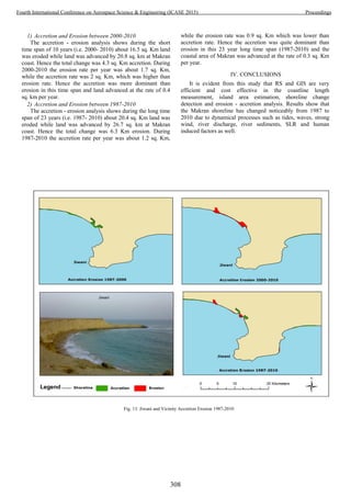
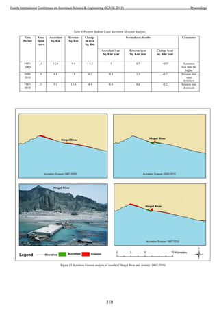

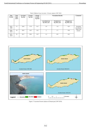


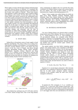
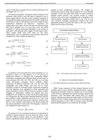
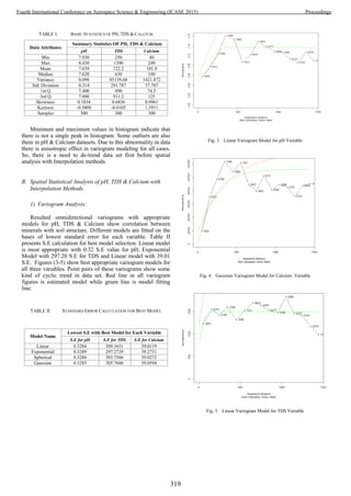
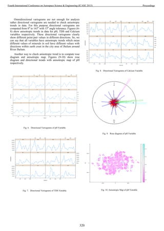
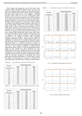
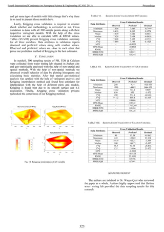


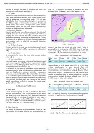


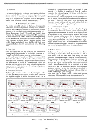
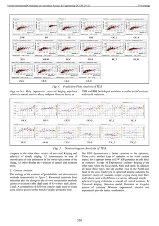
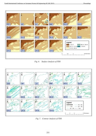


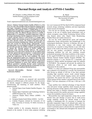
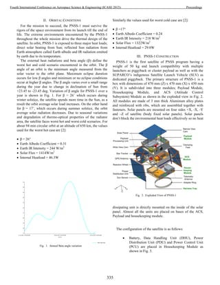
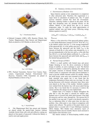
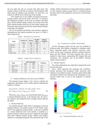
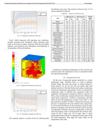


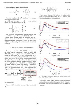
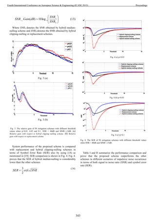


This document summarizes a study that compares the performance of two state observers - a sliding mode observer with super-twisting algorithm (STSMO) and a high gain observer (HGO) - for estimating unmeasured states of a quadrotor UAV. The paper designs each observer and then applies a second order sliding mode control technique using the estimated states to control the quadrotor. Simulations show the performance of each observer under the same control scheme and perturbations. The study aims to compare the observers' characteristics for state estimation of the quadrotor system to determine the best observer for real-time applications given system uncertainties and noise.