


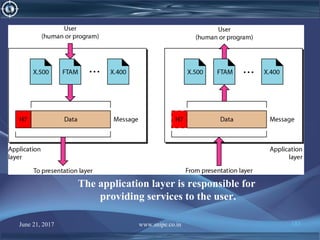
![June 21, 2017 www.snipe.co.in 22
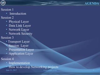
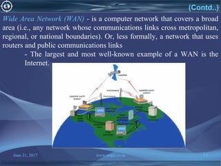
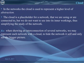
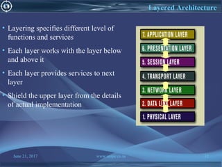
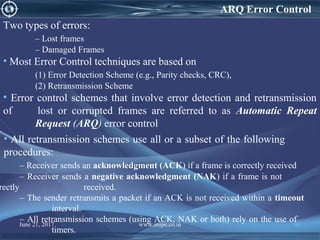
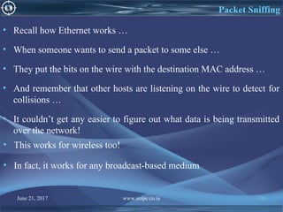
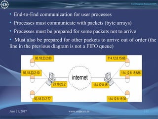
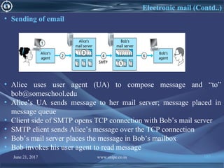
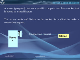
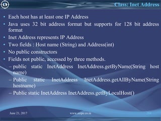
Types of nodes:
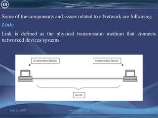
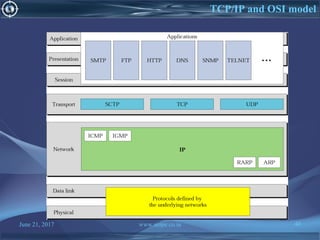
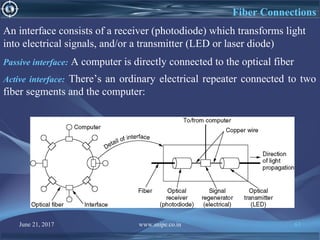
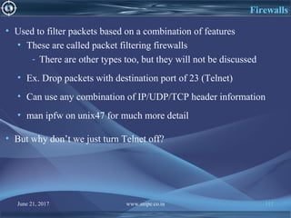
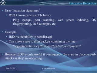
There are two types of nodes:
1. Nodes that use the network (Hosts)
It is the node that it does not participate in routing or packet switching.
They support users and run application programs.
2. Nodes that implement the Network (Switches/Routers/ Hubs/ Repeaters)
These are the networks nodes whose function is to implement the
functionality of the network (such as receiving data from end hosts and
forwarding to the other hosts [potentially through other network
implementing nodes]).](https://image.slidesharecdn.com/computernetwork-170621151237/85/Computer-network-22-320.jpg)


![June 21, 2017 www.snipe.co.in 75
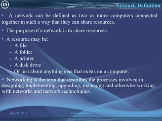
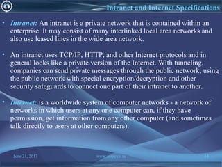
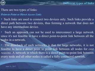
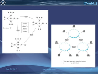
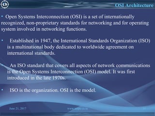
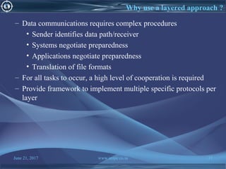
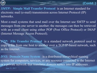
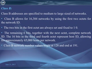
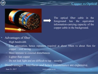
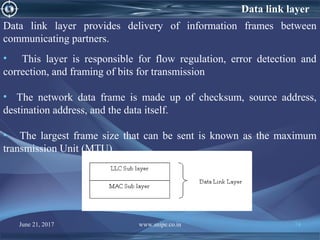
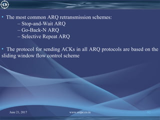
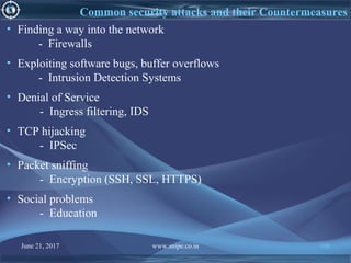
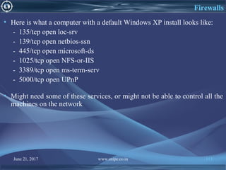
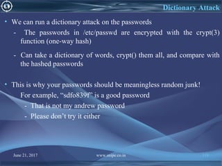
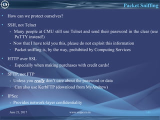
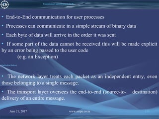
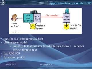
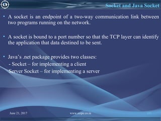
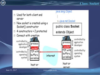
• Assembles bits into frames, making them ready for transmission over
the network.
• Provides error detection, and correction to transmitted frames. If the
checksum is not correct, it asks for retransmission. (Send a control
message).
• Consists of two sub layers:
- Logical Link Control (LLC): Defines how data is transferred over
the cable and provides data link service to the higher layers.
- Medium Access Control (MAC): Controls media access by
regulating the communicating nodes using pre-defined set of rules.
(i.e. Token passing, Ethernet [CSMA/CD] all have MAC sub-layer
protocol).
Features of Data Link Layer](https://image.slidesharecdn.com/computernetwork-170621151237/85/Computer-network-75-320.jpg)


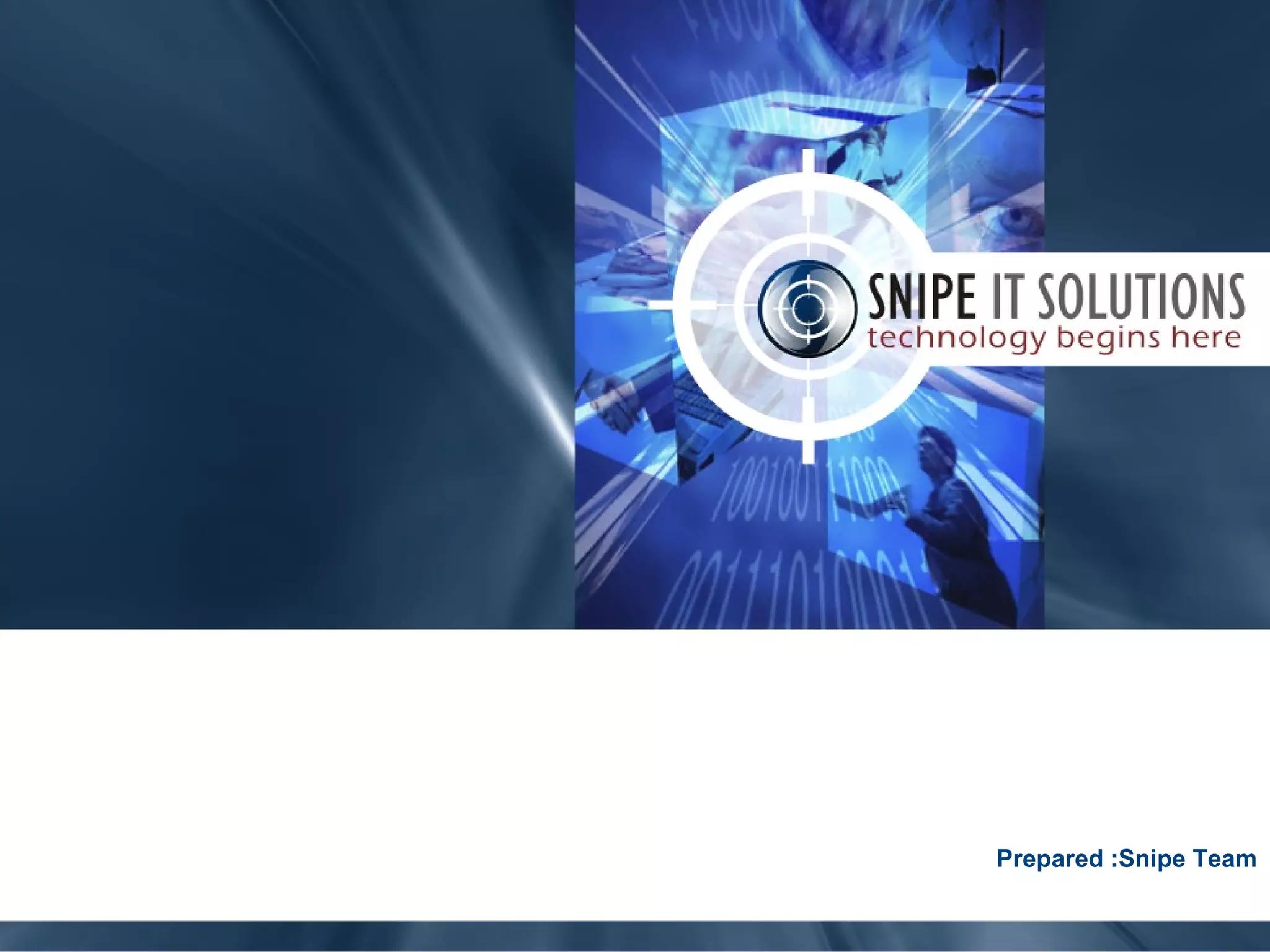
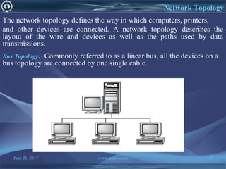
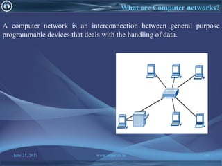
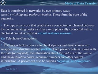
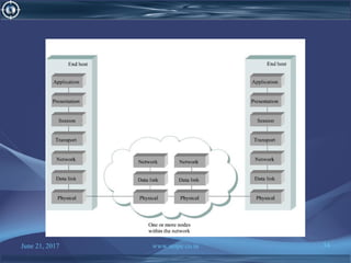
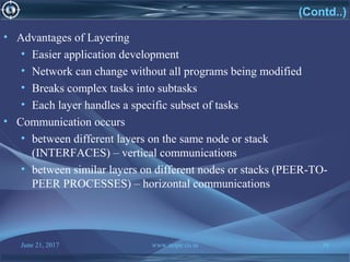
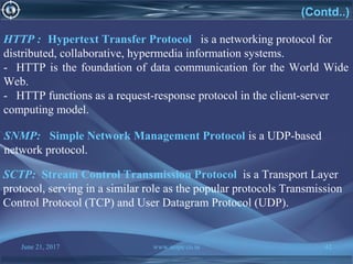
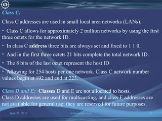
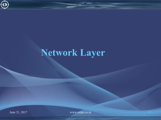
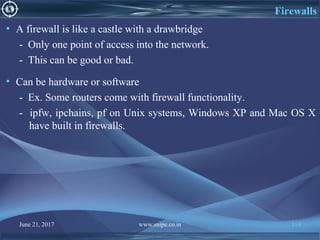
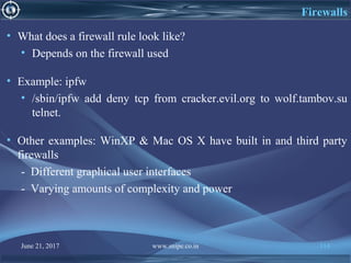
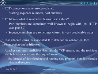
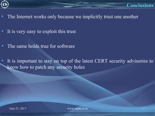
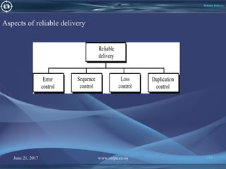
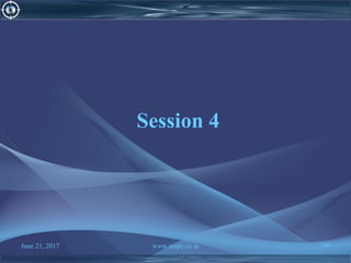
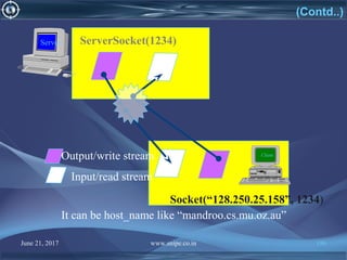
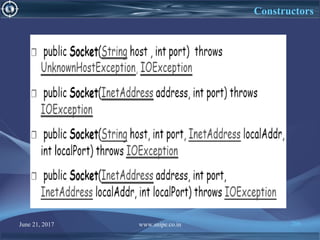
![Sliding Window Flow Control
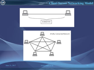
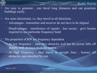
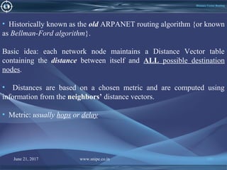
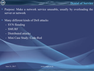
• Major Drawback of Stop-and-Wait Flow Control:
– Only one frame can be in transmission at a time
– This leads to inefficiency if a>1
• Sliding Window Flow Control
– Allows transmission of multiple frames
– Assigns each frame a k-bit sequence number
– Range of sequence number is [0..2k-1], i.e., frames are counted
modulo 2k
June 21, 2017 www.snipe.co.in 87](https://image.slidesharecdn.com/computernetwork-170621151237/85/Computer-network-87-320.jpg)


![June 21, 2017 www.snipe.co.in 215
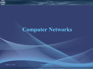
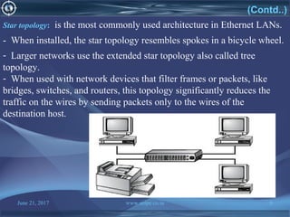
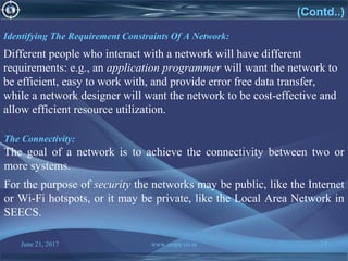
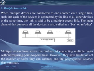
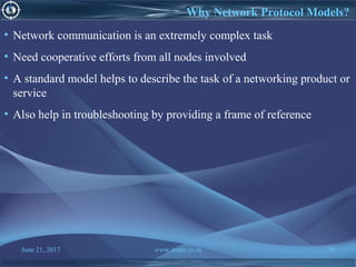
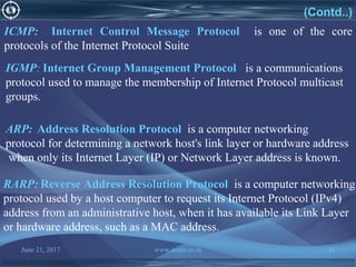
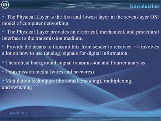
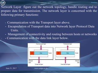
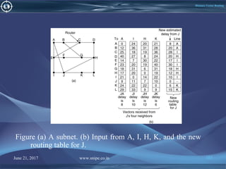
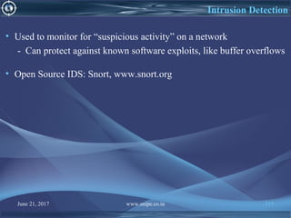
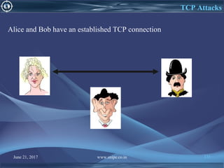
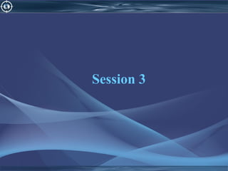
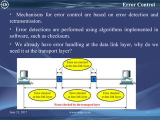
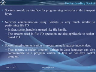
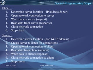
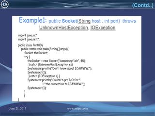
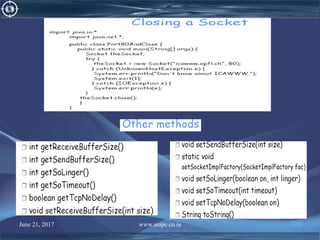
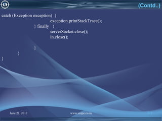
Server Code
import java.io.BufferedReader;
import java.io.IOException;
import java.io.InputStreamReader;
import java.io.PrintWriter;
import java.net.ServerSocket;
import java.net.Socket;
public class Server extends Thread{
public static void main(String[] args) throws IOException {
ServerSocket serverSocket = new ServerSocket(4444);
PrintWriter out = null;
BufferedReader in = null;
BufferedReader buffer = null;
String fromClient = null;
String input = null;
Socket client = null;](https://image.slidesharecdn.com/computernetwork-170621151237/85/Computer-network-215-320.jpg)
![June 21, 2017 www.snipe.co.in 218
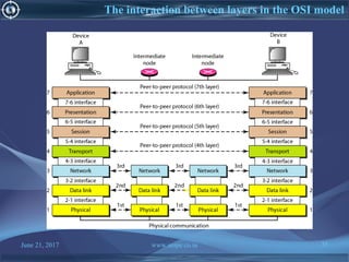
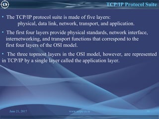
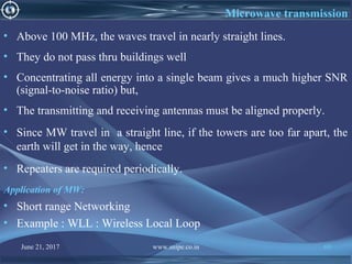
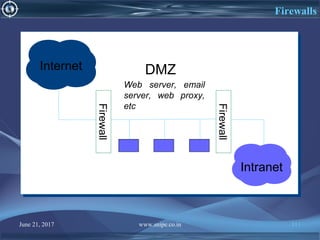
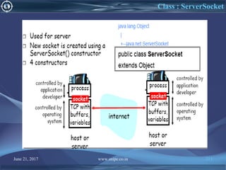
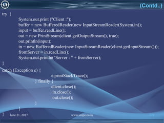
Client Code
import java.io.BufferedReader;
import java.io.IOException;
import java.io.InputStreamReader;
import java.io.PrintStream;
import java.net.Socket;
public class Client extends Thread {
public static void main(String[] args) throws IOException {
Socket client = new Socket ("localhost", 4444);
BufferedReader in = null;
BufferedReader buffer = null;
PrintStream out = null;
String fromServer = null;
String input = null;](https://image.slidesharecdn.com/computernetwork-170621151237/85/Computer-network-218-320.jpg)


![June 21, 2017 www.snipe.co.in 228
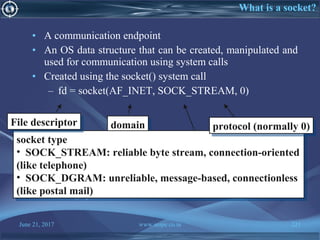
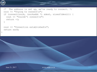
/* Name the socket
* (required before receiving connections)
*/
struct sockaddr_in s1;
bzero((char *) &s1, sizeof(s1)); /* They say to do this */
s1.sin_family = AF_INET;
s1.sin_addr.s_addr = INADDR_ANY; /* Use any of host’s addresses. */
s1.sin_port = 0; /* Have a port number assigned to us. */
if (bind(listener, (sockaddr *) &s1, sizeof(s1)) < 0) {
cerr << "Couldn't bind address to socketn";
return -1;
}
/* Get the host name. */
char hostname[48];
gethostname(hostname, 48);
/* Name the socket
* (required before receiving connections)
*/
struct sockaddr_in s1;
bzero((char *) &s1, sizeof(s1)); /* They say to do this */
s1.sin_family = AF_INET;
s1.sin_addr.s_addr = INADDR_ANY; /* Use any of host’s addresses. */
s1.sin_port = 0; /* Have a port number assigned to us. */
if (bind(listener, (sockaddr *) &s1, sizeof(s1)) < 0) {
cerr << "Couldn't bind address to socketn";
return -1;
}
/* Get the host name. */
char hostname[48];
gethostname(hostname, 48);](https://image.slidesharecdn.com/computernetwork-170621151237/85/Computer-network-228-320.jpg)
![June 21, 2017 www.snipe.co.in 230
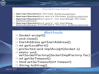
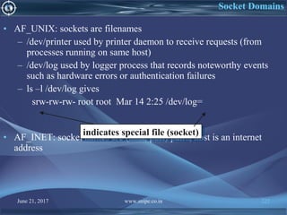
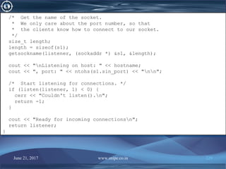
int main()
{
int listener = MakeListener();
if (listener < 0) return -1;
for (;;) {
/* Wait for, and then accept an incoming connection. */
cout << "Server waiting for connectionsn";
struct sockaddr_in s2;
size_t length = sizeof(s2);
int conn = accept(listener, (sockaddr *) &s2, &length);
/* We now have a connection to a client via
* file descriptor "conn".
*/
cout << "Server accepted connectionn";
/* Get a message from the client. */
char data[128];
int msglen = read(conn, data, 128);
cout << "Server got " << msglen << " byte message: " << data << "n";
int main()
{
int listener = MakeListener();
if (listener < 0) return -1;
for (;;) {
/* Wait for, and then accept an incoming connection. */
cout << "Server waiting for connectionsn";
struct sockaddr_in s2;
size_t length = sizeof(s2);
int conn = accept(listener, (sockaddr *) &s2, &length);
/* We now have a connection to a client via
* file descriptor "conn".
*/
cout << "Server accepted connectionn";
/* Get a message from the client. */
char data[128];
int msglen = read(conn, data, 128);
cout << "Server got " << msglen << " byte message: " << data << "n";](https://image.slidesharecdn.com/computernetwork-170621151237/85/Computer-network-230-320.jpg)

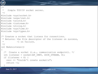
![June 21, 2017 www.snipe.co.in 233
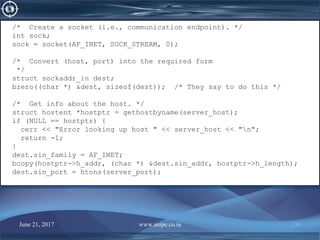
/*
* Simple TCP/IP socket client.
*/
#include <sys/socket.h>
#include <netdb.h>
#include <arpa/inet.h>
#include <unistd.h>
#include <stdio.h>
#include <string.h>
#include <iostream.h>
int ServerConnect() {
/* Establishes a TCP/IP connection with the server.
* The user is prompted for the hostname and port number.
* Returns: the file descriptor of the socket on success,
* -1 on failure
*/
char server_host[80];
u_short server_port;
cout << "Enter the hostname the server is running onn";
cin.getline(server_host, 80);
cout << "Enter the port number the server is listening onn";
cin >> server_port;
cin.ignore(1,'n');
/*
* Simple TCP/IP socket client.
*/
#include <sys/socket.h>
#include <netdb.h>
#include <arpa/inet.h>
#include <unistd.h>
#include <stdio.h>
#include <string.h>
#include <iostream.h>
int ServerConnect() {
/* Establishes a TCP/IP connection with the server.
* The user is prompted for the hostname and port number.
* Returns: the file descriptor of the socket on success,
* -1 on failure
*/
char server_host[80];
u_short server_port;
cout << "Enter the hostname the server is running onn";
cin.getline(server_host, 80);
cout << "Enter the port number the server is listening onn";
cin >> server_port;
cin.ignore(1,'n');](https://image.slidesharecdn.com/computernetwork-170621151237/85/Computer-network-233-320.jpg)
![June 21, 2017 www.snipe.co.in 236
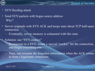
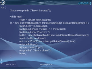
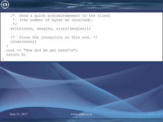
int main()
{
int conn = ServerConnect();
if (conn < 0) return -1;
char message[128];
int ack;
cout << "Enter message for server:n";
cin.getline(message, 128);
/* Send the message to the server. */
write(conn, message, 1+strlen(message));
/* Get the ack from the server. */
read(conn, &ack, sizeof(ack));
cout << "The server got " << ack << " bytesn";
/* Close the connection on this end. */
close(conn);
return 0;
}
int main()
{
int conn = ServerConnect();
if (conn < 0) return -1;
char message[128];
int ack;
cout << "Enter message for server:n";
cin.getline(message, 128);
/* Send the message to the server. */
write(conn, message, 1+strlen(message));
/* Get the ack from the server. */
read(conn, &ack, sizeof(ack));
cout << "The server got " << ack << " bytesn";
/* Close the connection on this end. */
close(conn);
return 0;
}](https://image.slidesharecdn.com/computernetwork-170621151237/85/Computer-network-236-320.jpg)

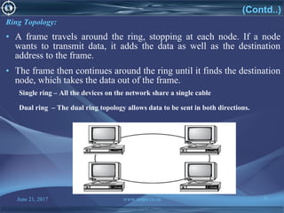
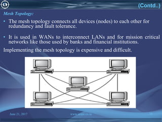
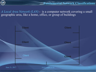
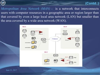
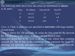
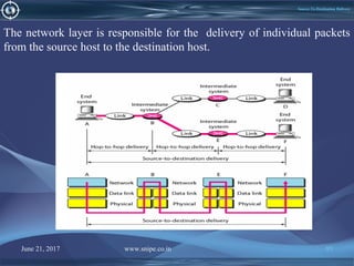
This document provides an overview of computer networks. It discusses the agenda and definitions of networks, advantages of networking, common network topologies including bus, star, ring and mesh. It also describes fundamental network classifications like LAN, MAN and WAN. The document outlines applications of networks and defines key components like links, nodes, switches, routers and hubs. It concludes with a discussion of cloud computing and modes of data transfer in networks.