Hardcopy Technologies
• Hardcopyis a printed copy of information from a computer.
Sometimes it refer to as a printout, so it called hardcopy because it
exists as a physical object. Hardcopy is tangible output that
usually printed. The principal examples are printouts, whether text
or graphics, form printers and also films including microfilms and
microfiche is also considered as hardcopy output. Output Devices
It is an electromechanical device, which accepts data from a
computer and translates them into form understand by users.
Following are Output Devices:
1. Printers
2. Plotters
3.
Printers:
A printer isa peripheral device which is used to represent the graphics or text on paper. The quality is
measured by its resolution. The resolution of any printer is measured in dot per inch (dpi). The printer
usually works with the computer and connected via a cable. In present, many digital device support
printer features so that we can use Bluetooth, Wi-fi, and cloud technology to print.
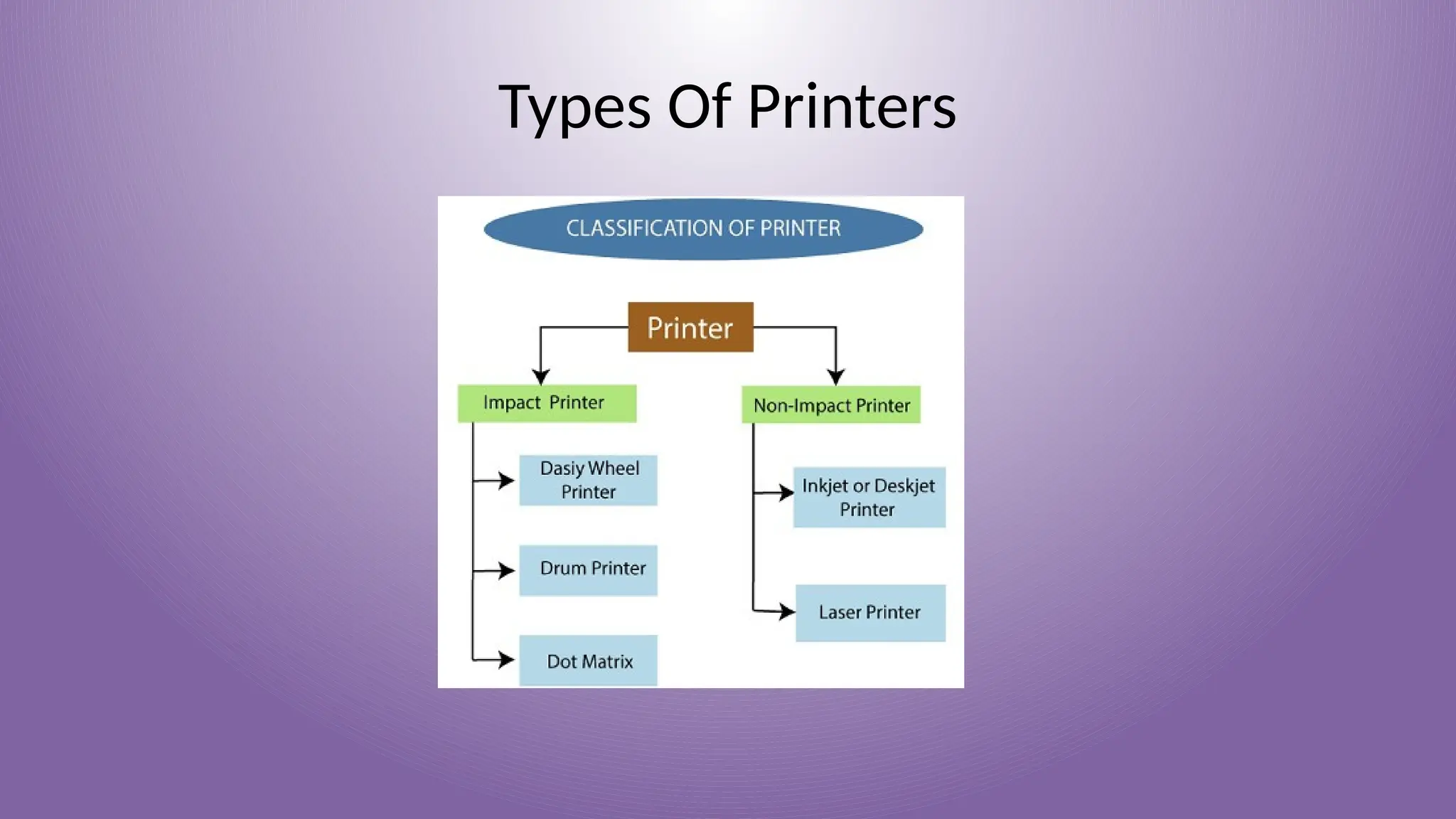
Some types of printers are:
➢ Impact Printers
➢ Non-impact Printers
Impact Printers In impact printers, there is a physical contact established between the print head, ribbon,
ink-cartridge, and paper. The printers hit print head on an ink-filled ribbon than the letter prints on the
paper. Impact printers are works like a typewriter.
These printers have three types:
➢ Daisy Wheel Printers
➢ Drum Printers
➢ Dot Matrix Printer
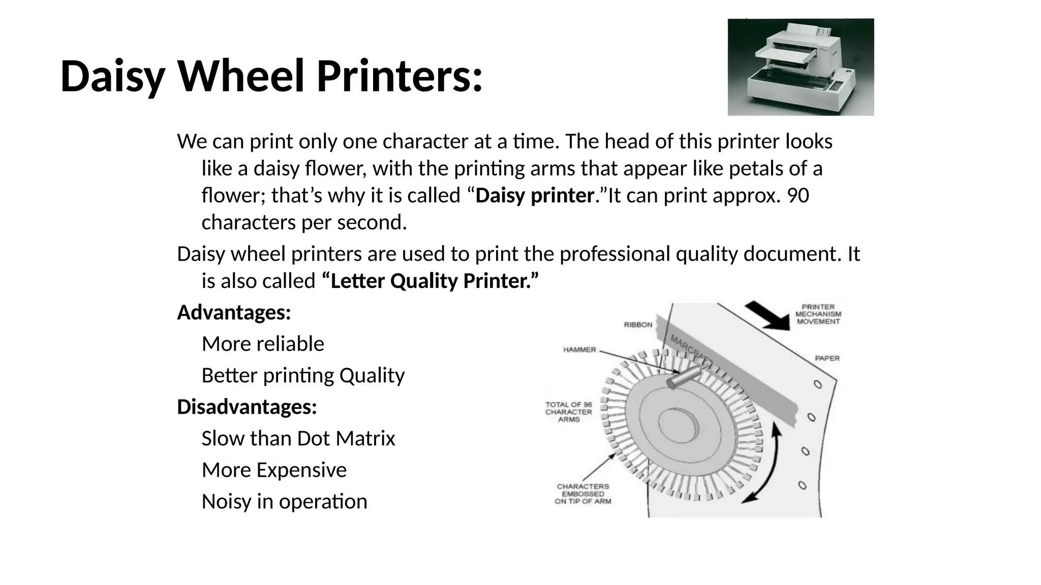
Daisy Wheel Printers:
Wecan print only one character at a time. The head of this printer looks
like a daisy flower, with the printing arms that appear like petals of a
flower; that’s why it is called “Daisy printer.”It can print approx. 90
characters per second.
Daisy wheel printers are used to print the professional quality document. It
is also called “Letter Quality Printer.”
Advantages:
More reliable
Better printing Quality
Disadvantages:
Slow than Dot Matrix
More Expensive
Noisy in operation
6.
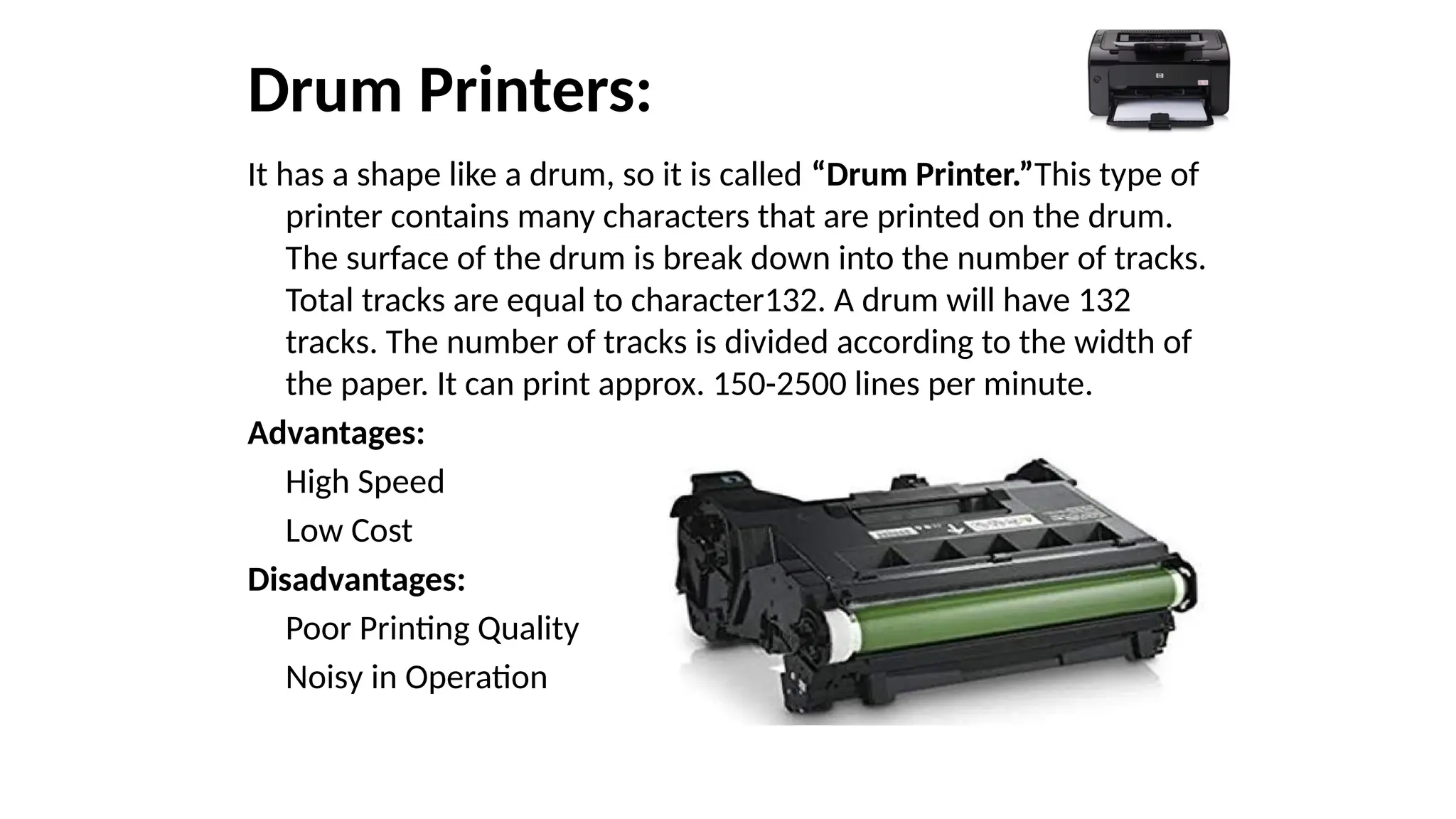
Drum Printers:
It hasa shape like a drum, so it is called “Drum Printer.”This type of
printer contains many characters that are printed on the drum.
The surface of the drum is break down into the number of tracks.
Total tracks are equal to character132. A drum will have 132
tracks. The number of tracks is divided according to the width of
the paper. It can print approx. 150-2500 lines per minute.
Advantages:
High Speed
Low Cost
Disadvantages:
Poor Printing Quality
Noisy in Operation
7.
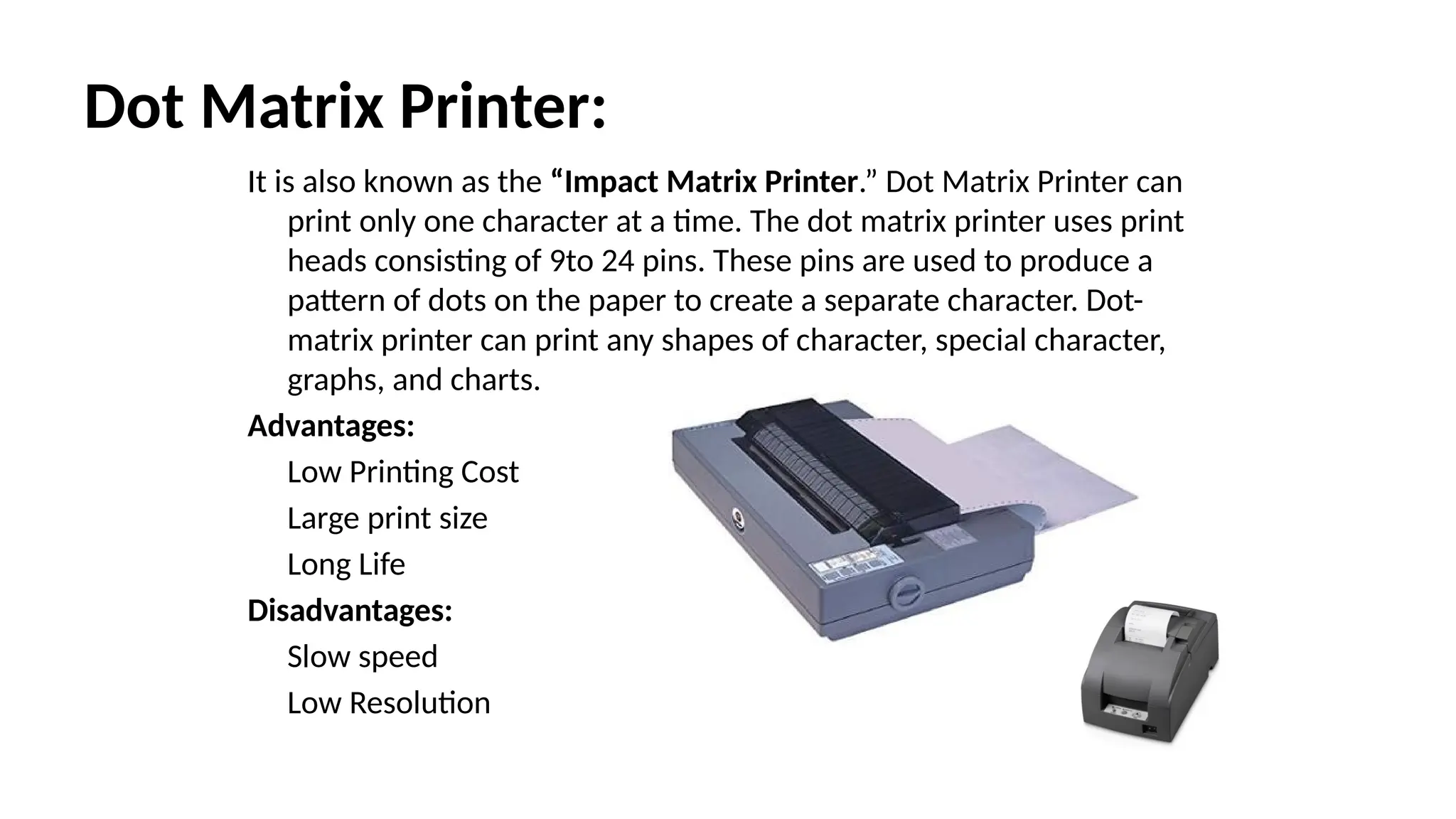
Dot Matrix Printer:
Itis also known as the “Impact Matrix Printer.” Dot Matrix Printer can
print only one character at a time. The dot matrix printer uses print
heads consisting of 9to 24 pins. These pins are used to produce a
pattern of dots on the paper to create a separate character. Dot-
matrix printer can print any shapes of character, special character,
graphs, and charts.
Advantages:
Low Printing Cost
Large print size
Long Life
Disadvantages:
Slow speed
Low Resolution
8.
Non-impact Printers
• InNon-impact printers, there is no physical contact between the print
head or paper head. A non-impact printer prints a complete page at a
time. The Non-impact printers spray ink on the paper through nozzles
to form the letters and patterns. The printers that print the letters
without the ribbon and on papers are called Non-impact printer. Non-
impact printers are also known as “Page Printer.”
These printer shave two types:
• Inkjet Printer
• Laser Printer
9.
Inkjet Printer:
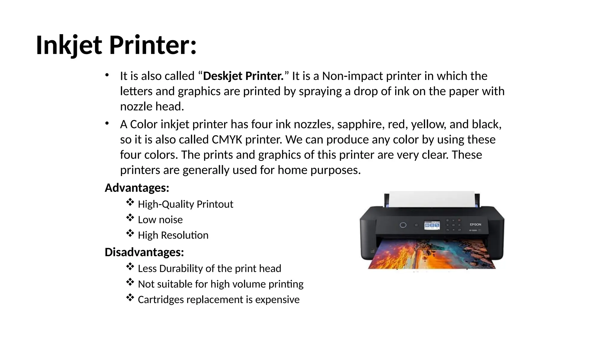
• Itis also called “Deskjet Printer.” It is a Non-impact printer in which the
letters and graphics are printed by spraying a drop of ink on the paper with
nozzle head.
• A Color inkjet printer has four ink nozzles, sapphire, red, yellow, and black,
so it is also called CMYK printer. We can produce any color by using these
four colors. The prints and graphics of this printer are very clear. These
printers are generally used for home purposes.
Advantages:
High-Quality Printout
Low noise
High Resolution
Disadvantages:
Less Durability of the print head
Not suitable for high volume printing
Cartridges replacement is expensive
10.
Laser Printer:
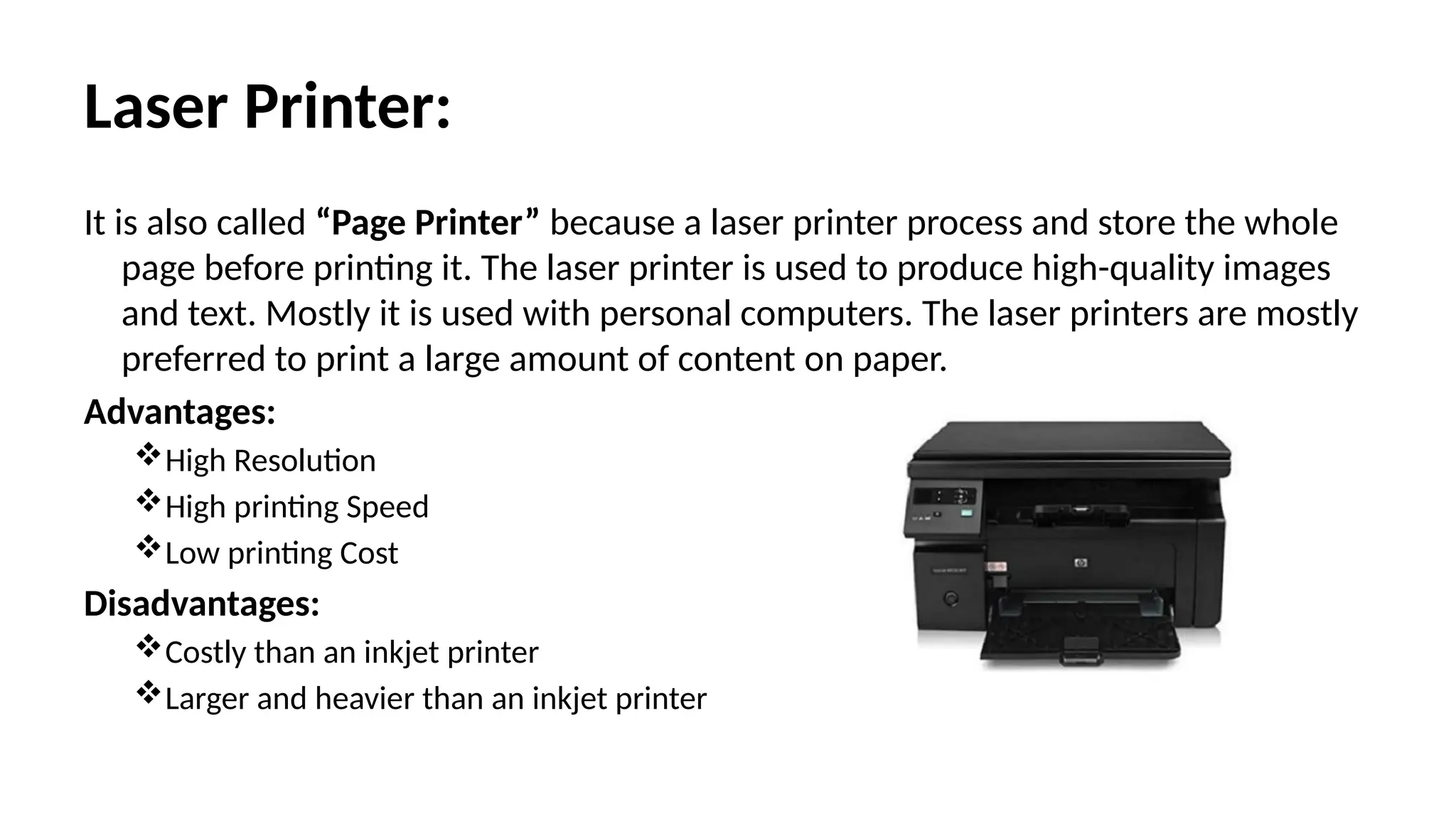
It isalso called “Page Printer” because a laser printer process and store the whole
page before printing it. The laser printer is used to produce high-quality images
and text. Mostly it is used with personal computers. The laser printers are mostly
preferred to print a large amount of content on paper.
Advantages:
High Resolution
High printing Speed
Low printing Cost
Disadvantages:
Costly than an inkjet printer
Larger and heavier than an inkjet printer
11.
Plotters:
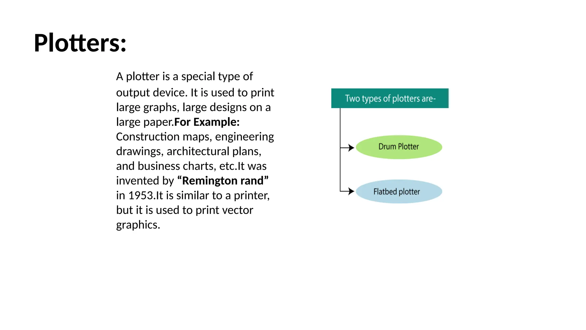
A plotter isa special type of
output device. It is used to print
large graphs, large designs on a
large paper.For Example:
Construction maps, engineering
drawings, architectural plans,
and business charts, etc.It was
invented by “Remington rand”
in 1953.It is similar to a printer,
but it is used to print vector
graphics.
12.
Flatbed Plotter:
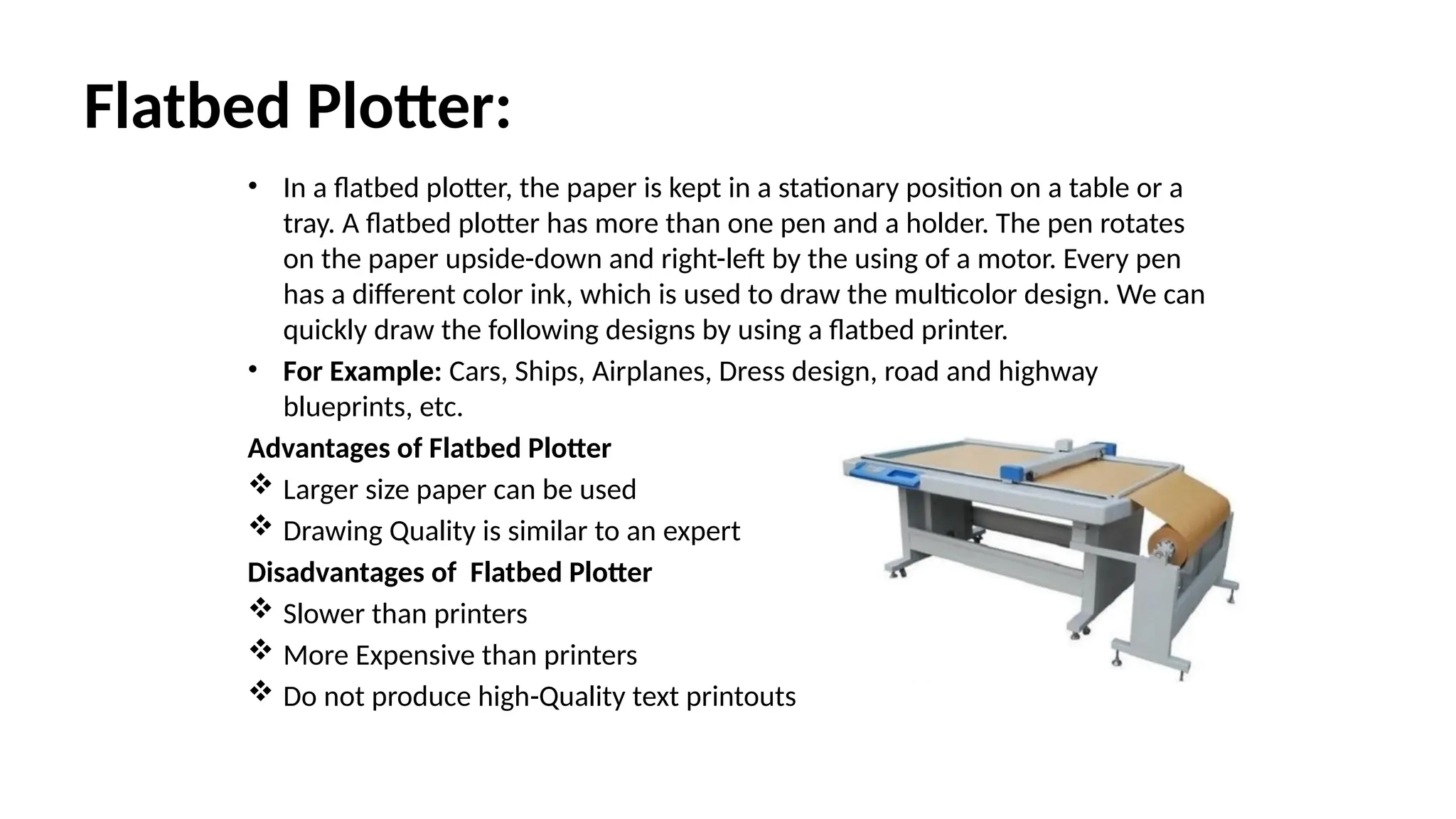
• Ina flatbed plotter, the paper is kept in a stationary position on a table or a
tray. A flatbed plotter has more than one pen and a holder. The pen rotates
on the paper upside-down and right-left by the using of a motor. Every pen
has a different color ink, which is used to draw the multicolor design. We can
quickly draw the following designs by using a flatbed printer.
• For Example: Cars, Ships, Airplanes, Dress design, road and highway
blueprints, etc.
Advantages of Flatbed Plotter
Larger size paper can be used
Drawing Quality is similar to an expert
Disadvantages of Flatbed Plotter
Slower than printers
More Expensive than printers
Do not produce high-Quality text printouts
13.
Drum Plotter:
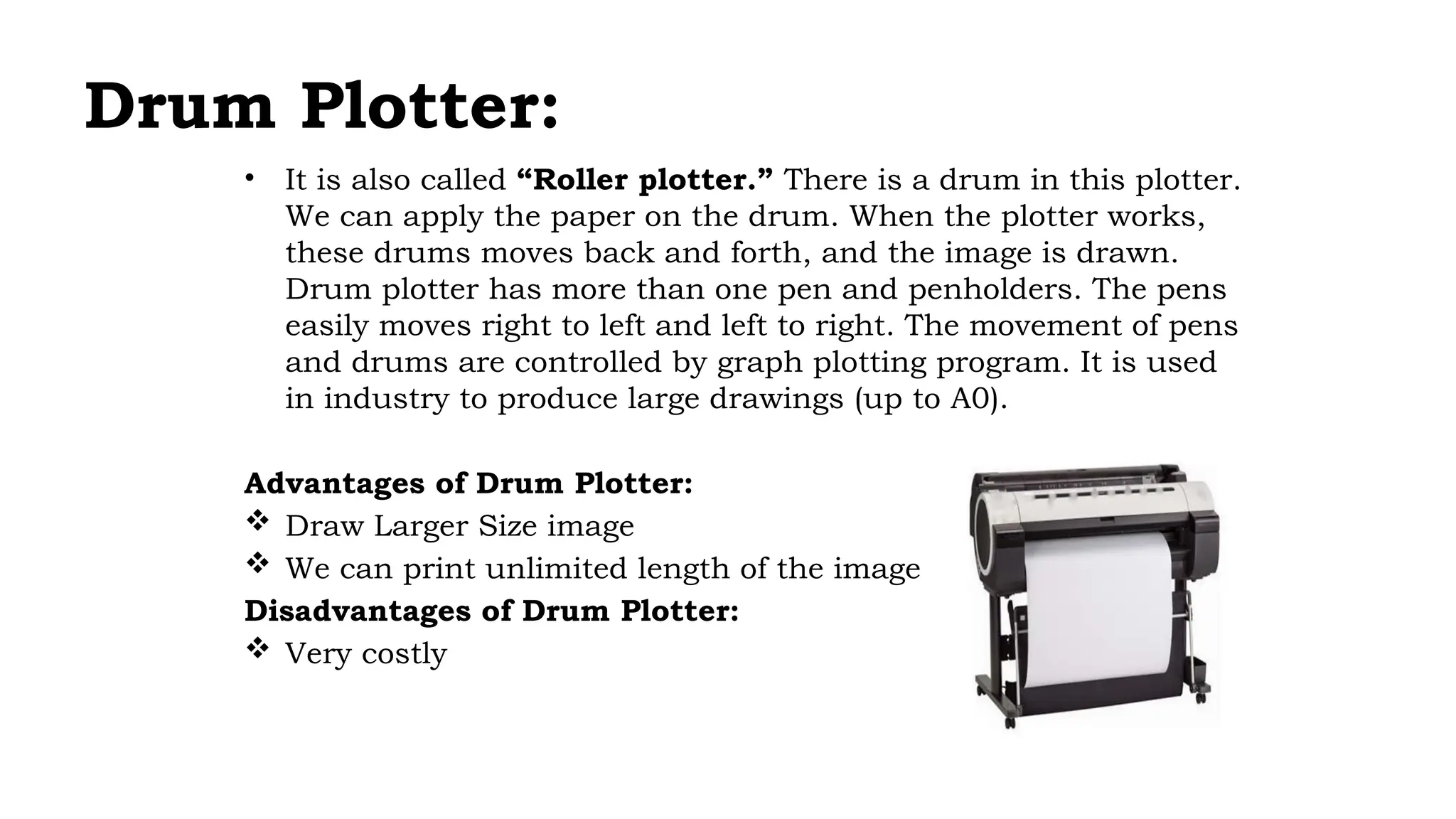
• Itis also called “Roller plotter.” There is a drum in this plotter.
We can apply the paper on the drum. When the plotter works,
these drums moves back and forth, and the image is drawn.
Drum plotter has more than one pen and penholders. The pens
easily moves right to left and left to right. The movement of pens
and drums are controlled by graph plotting program. It is used
in industry to produce large drawings (up to A0).
Advantages of Drum Plotter:
Draw Larger Size image
We can print unlimited length of the image
Disadvantages of Drum Plotter:
Very costly
14.
Visual Display Devices:
Theprimary output device in a graphics system is a video monitor. Although many
technologies exist, but the operation of most video monitors is based on the standard
Cathode Ray Tube (CRT) design.
Cathode Ray Tubes (CRT):
A cathode ray tube (CRT) is a specialized vacuum tube in which images are produced when an
electron beam strikes a phosphorescent surface. It modulates, accelerates, and deflects
electron beam(s) onto the screen to create the images. Most desktop computer displays
make use of CRT for image displaying purposes.
Construction of a CRT:
1. The primary components are the heated metal cathode and a control grid.
2. The heat is supplied to the cathode (by passing current through the filament).
3. This way the electrons get heated up and start getting ejected out of the cathode
filament.
4. This stream of negatively charged electrons is accelerated towards the phosphor screen
by supplying a high positive voltage.
5. This acceleration is generally produced by means of an accelerating a node.
15.
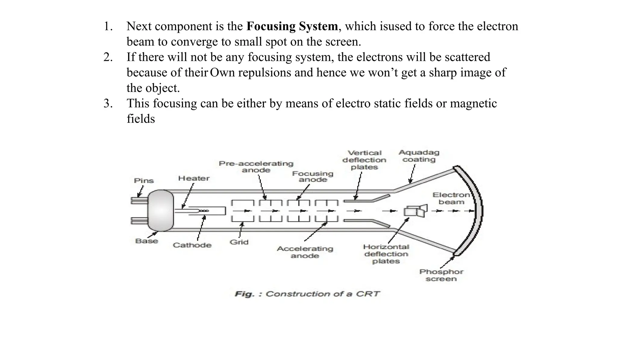
1. Next componentis the Focusing System, which isused to force the electron
beam to converge to small spot on the screen.
2. If there will not be any focusing system, the electrons will be scattered
because of theirOwn repulsions and hence we won’t get a sharp image of
the object.
3. This focusing can be either by means of electro static fields or magnetic
fields
16.
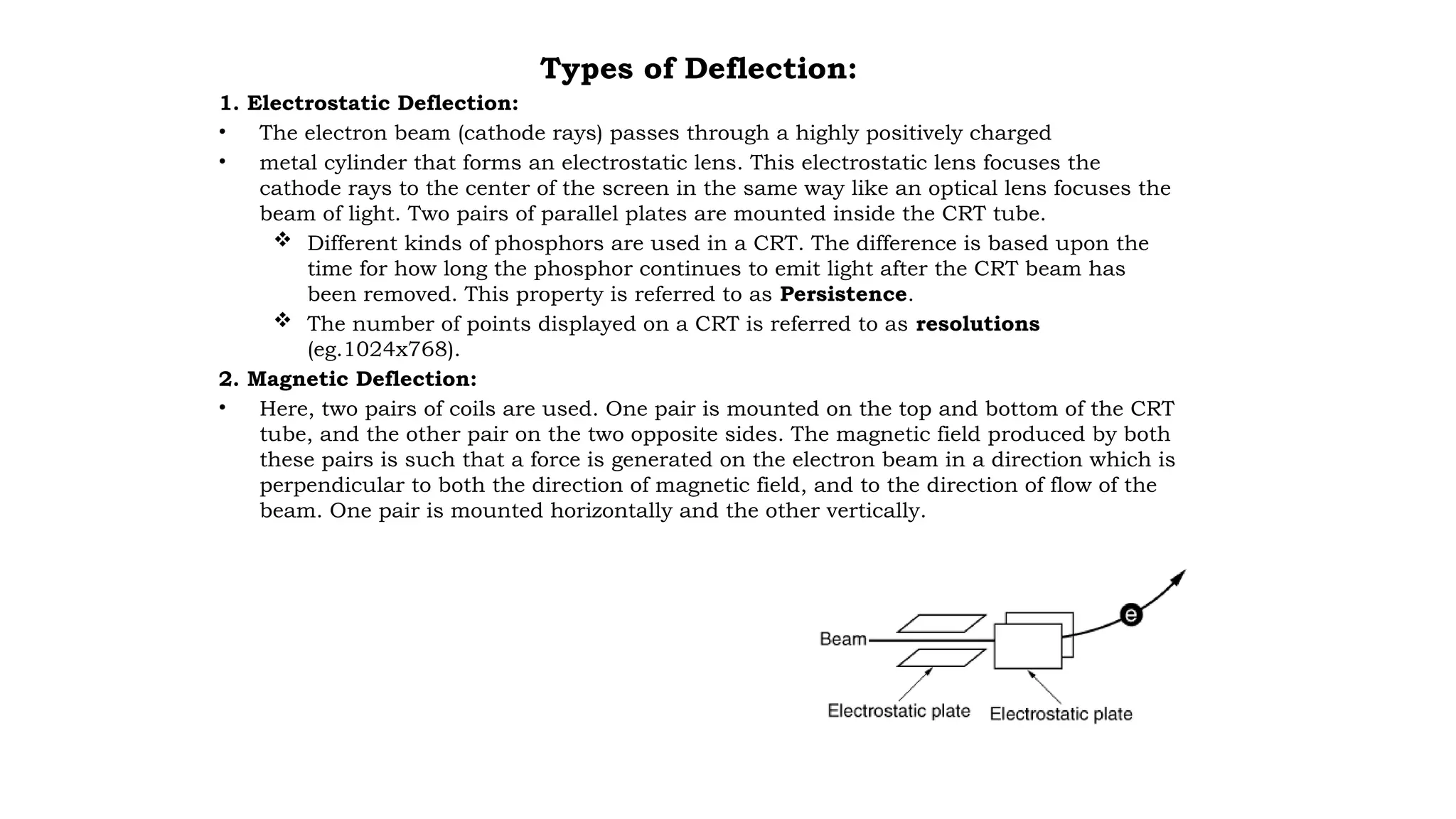
Types of Deflection:
1.Electrostatic Deflection:
• The electron beam (cathode rays) passes through a highly positively charged
• metal cylinder that forms an electrostatic lens. This electrostatic lens focuses the
cathode rays to the center of the screen in the same way like an optical lens focuses the
beam of light. Two pairs of parallel plates are mounted inside the CRT tube.
Different kinds of phosphors are used in a CRT. The difference is based upon the
time for how long the phosphor continues to emit light after the CRT beam has
been removed. This property is referred to as Persistence.
The number of points displayed on a CRT is referred to as resolutions
(eg.1024x768).
2. Magnetic Deflection:
• Here, two pairs of coils are used. One pair is mounted on the top and bottom of the CRT
tube, and the other pair on the two opposite sides. The magnetic field produced by both
these pairs is such that a force is generated on the electron beam in a direction which is
perpendicular to both the direction of magnetic field, and to the direction of flow of the
beam. One pair is mounted horizontally and the other vertically.
17.
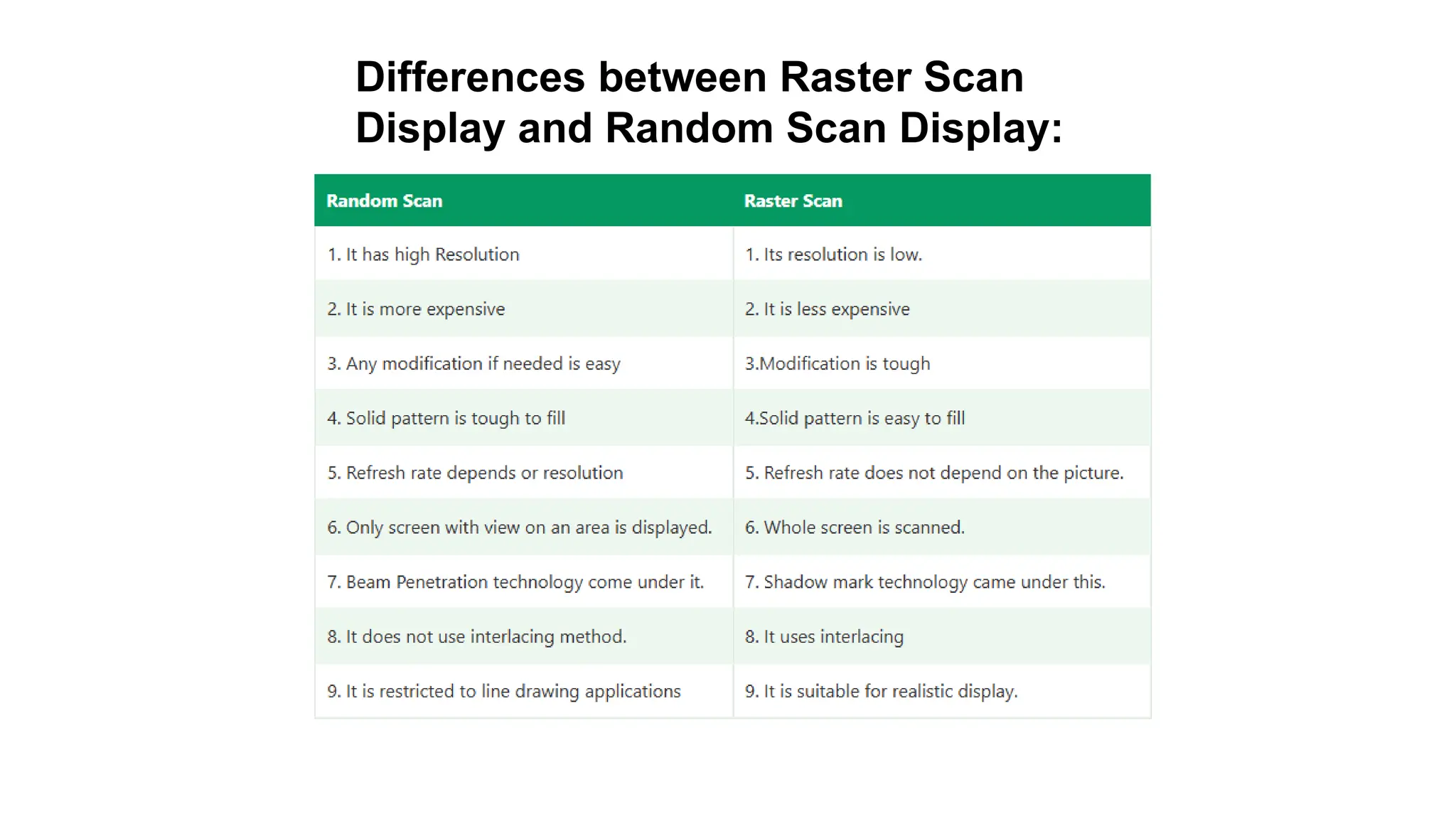
Raster-Scan Display
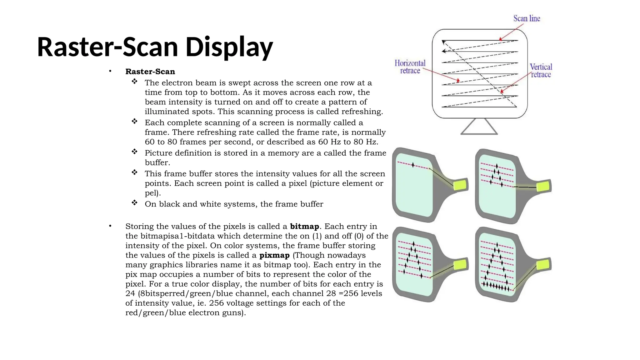
• Raster-Scan
The electron beam is swept across the screen one row at a
time from top to bottom. As it moves across each row, the
beam intensity is turned on and off to create a pattern of
illuminated spots. This scanning process is called refreshing.
Each complete scanning of a screen is normally called a
frame. There refreshing rate called the frame rate, is normally
60 to 80 frames per second, or described as 60 Hz to 80 Hz.
Picture definition is stored in a memory are a called the frame
buffer.
This frame buffer stores the intensity values for all the screen
points. Each screen point is called a pixel (picture element or
pel).
On black and white systems, the frame buffer
• Storing the values of the pixels is called a bitmap. Each entry in
the bitmapisa1-bitdata which determine the on (1) and off (0) of the
intensity of the pixel. On color systems, the frame buffer storing
the values of the pixels is called a pixmap (Though nowadays
many graphics libraries name it as bitmap too). Each entry in the
pix map occupies a number of bits to represent the color of the
pixel. For a true color display, the number of bits for each entry is
24 (8bitsperred/green/blue channel, each channel 28 =256 levels
of intensity value, ie. 256 voltage settings for each of the
red/green/blue electron guns).
18.
Random-Scan(Vector Display)or stroke-writingor
calligraphic displays:
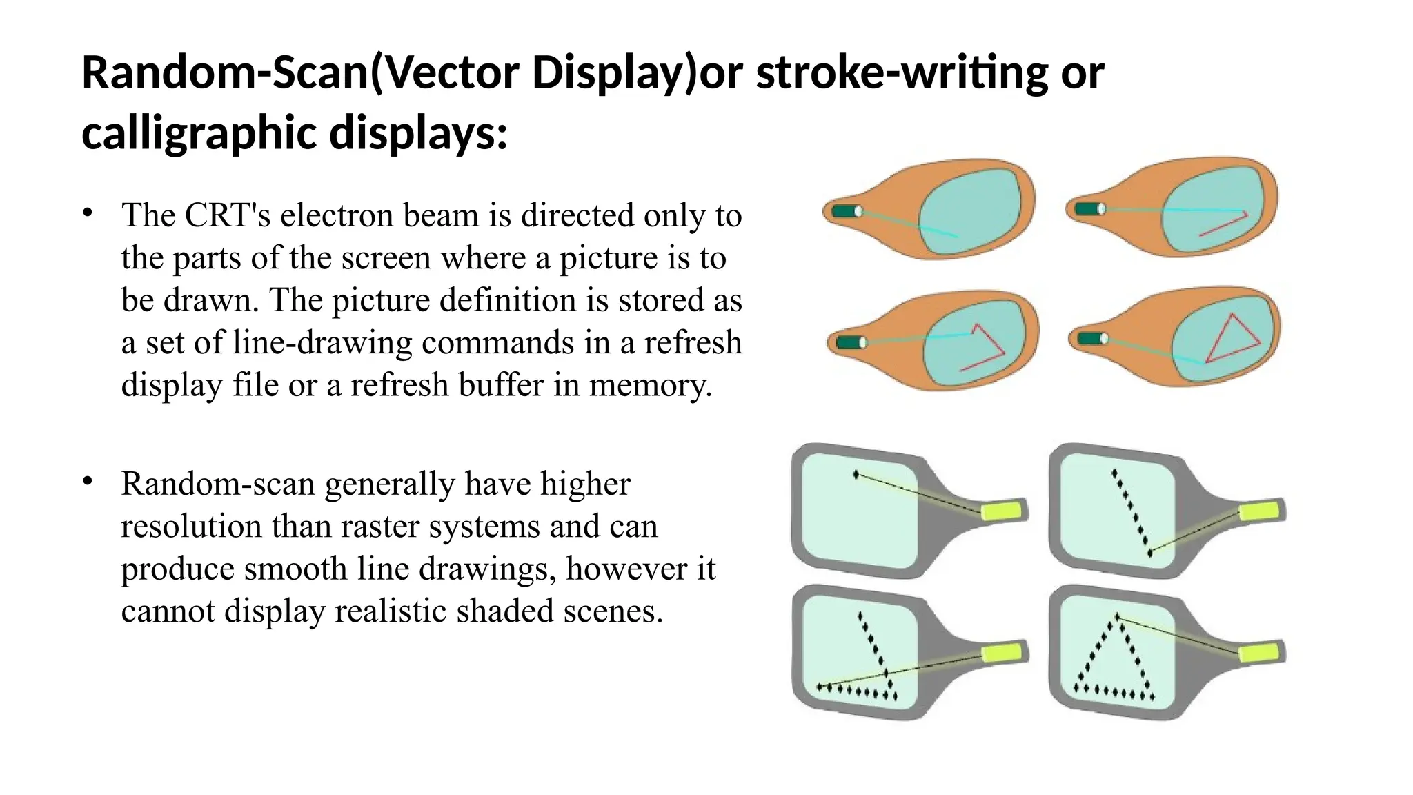
• The CRT's electron beam is directed only to
the parts of the screen where a picture is to
be drawn. The picture definition is stored as
a set of line-drawing commands in a refresh
display file or a refresh buffer in memory.
• Random-scan generally have higher
resolution than raster systems and can
produce smooth line drawings, however it
cannot display realistic shaded scenes.
19.
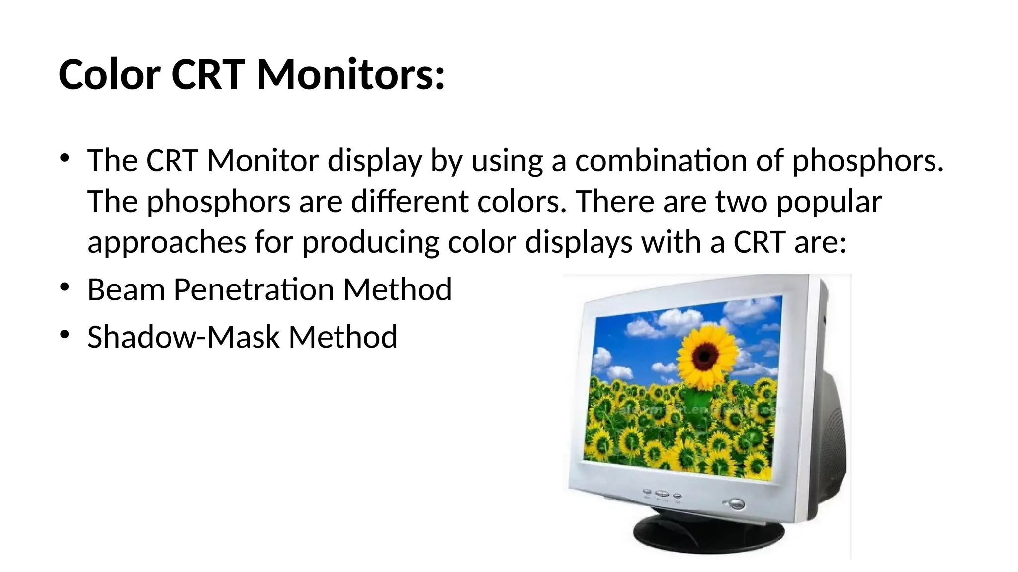
Color CRT Monitors:
•The CRT Monitor display by using a combination of phosphors.
The phosphors are different colors. There are two popular
approaches for producing color displays with a CRT are:
• Beam Penetration Method
• Shadow-Mask Method
20.
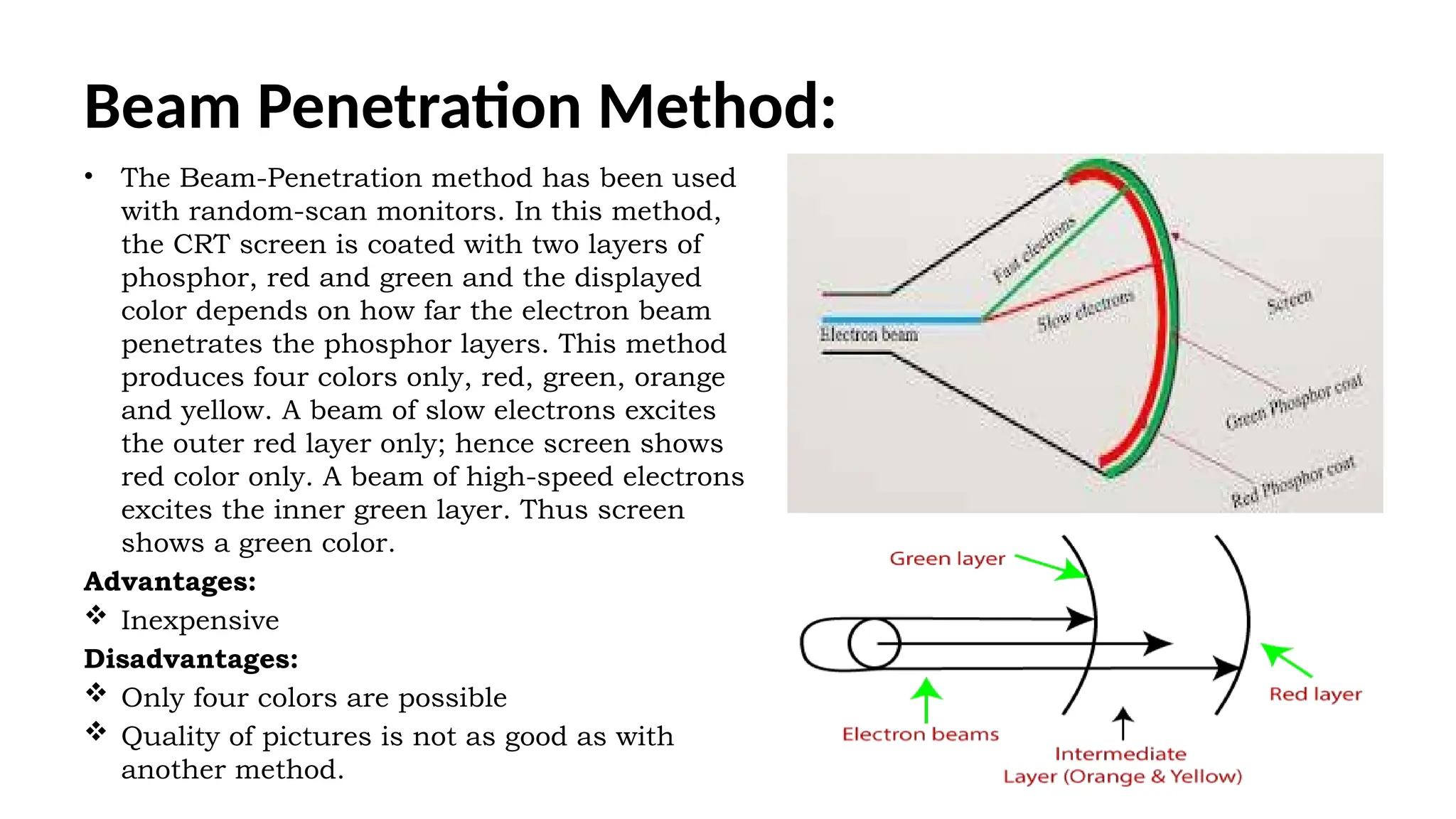
Beam Penetration Method:
•The Beam-Penetration method has been used
with random-scan monitors. In this method,
the CRT screen is coated with two layers of
phosphor, red and green and the displayed
color depends on how far the electron beam
penetrates the phosphor layers. This method
produces four colors only, red, green, orange
and yellow. A beam of slow electrons excites
the outer red layer only; hence screen shows
red color only. A beam of high-speed electrons
excites the inner green layer. Thus screen
shows a green color.
Advantages:
Inexpensive
Disadvantages:
Only four colors are possible
Quality of pictures is not as good as with
another method.
21.
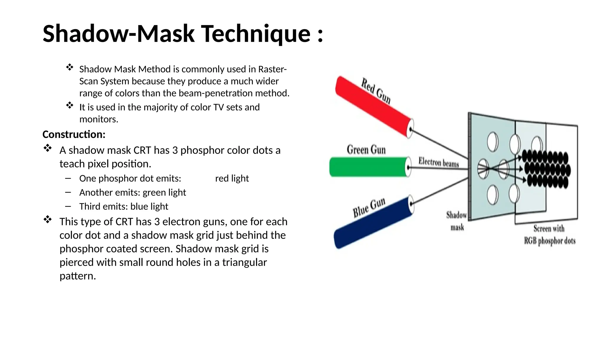
Shadow-Mask Technique :
Shadow Mask Method is commonly used in Raster-
Scan System because they produce a much wider
range of colors than the beam-penetration method.
It is used in the majority of color TV sets and
monitors.
Construction:
A shadow mask CRT has 3 phosphor color dots a
teach pixel position.
– One phosphor dot emits: red light
– Another emits: green light
– Third emits: blue light
This type of CRT has 3 electron guns, one for each
color dot and a shadow mask grid just behind the
phosphor coated screen. Shadow mask grid is
pierced with small round holes in a triangular
pattern.
22.
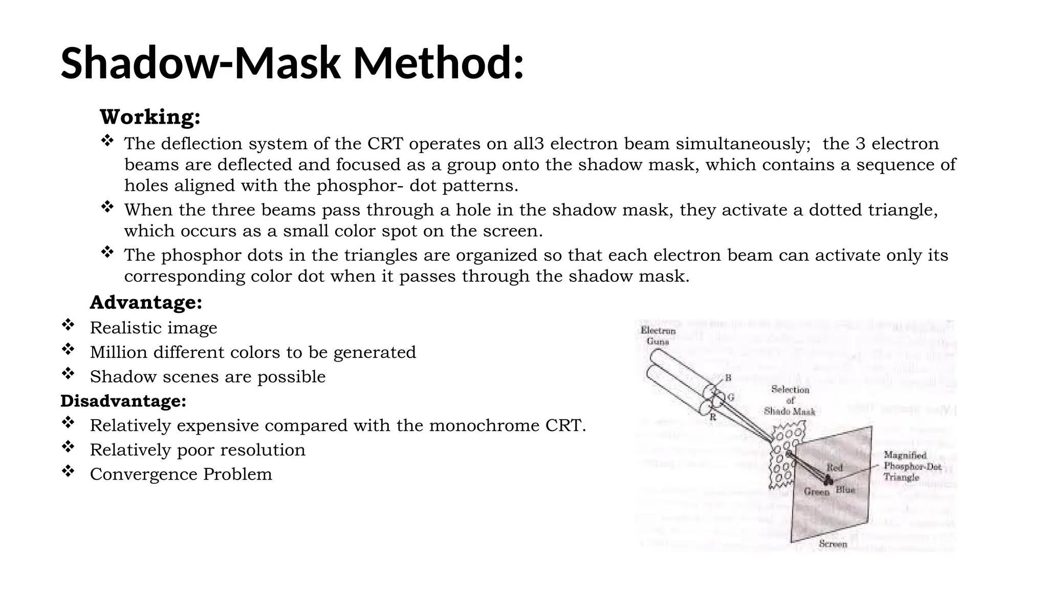
Shadow-Mask Method:
Working:
Thedeflection system of the CRT operates on all3 electron beam simultaneously; the 3 electron
beams are deflected and focused as a group onto the shadow mask, which contains a sequence of
holes aligned with the phosphor- dot patterns.
When the three beams pass through a hole in the shadow mask, they activate a dotted triangle,
which occurs as a small color spot on the screen.
The phosphor dots in the triangles are organized so that each electron beam can activate only its
corresponding color dot when it passes through the shadow mask.
Advantage:
Realistic image
Million different colors to be generated
Shadow scenes are possible
Disadvantage:
Relatively expensive compared with the monochrome CRT.
Relatively poor resolution
Convergence Problem
23.
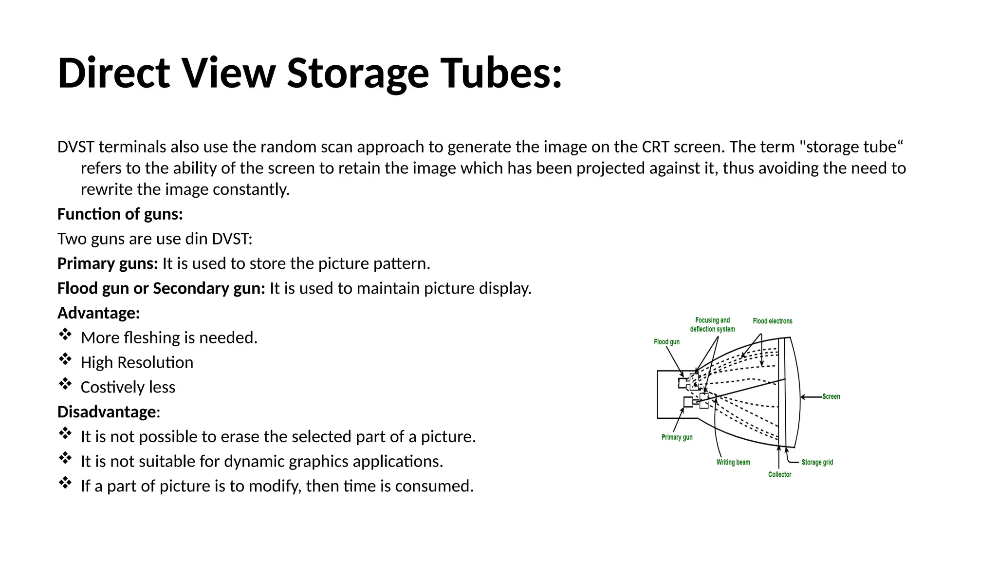
Direct View StorageTubes:
DVST terminals also use the random scan approach to generate the image on the CRT screen. The term "storage tube“
refers to the ability of the screen to retain the image which has been projected against it, thus avoiding the need to
rewrite the image constantly.
Function of guns:
Two guns are use din DVST:
Primary guns: It is used to store the picture pattern.
Flood gun or Secondary gun: It is used to maintain picture display.
Advantage:
More fleshing is needed.
High Resolution
Costively less
Disadvantage:
It is not possible to erase the selected part of a picture.
It is not suitable for dynamic graphics applications.
If a part of picture is to modify, then time is consumed.
24.
Flat Panel Display:
TheFlat-Panel display refers to a class of video devices that have reduced
volume, weight and power requirement compare to CRT.
Example: Small T.V. monitor, calculator, pocket video games, laptop
computers, an advertisement board in elevator.
Emissive Display:
• The emissive displays are devices that convert electrical energy into light.
Examples are Plasma Panel, thin film electroluminescent display and LED
(Light Emitting Diodes).
• Non-Emissive Display:
• The Non-Emissive displays use optical effects to convert sunlight or light
from some other source into graphics patterns. Examples are LCD (Liquid
Crystal Device).
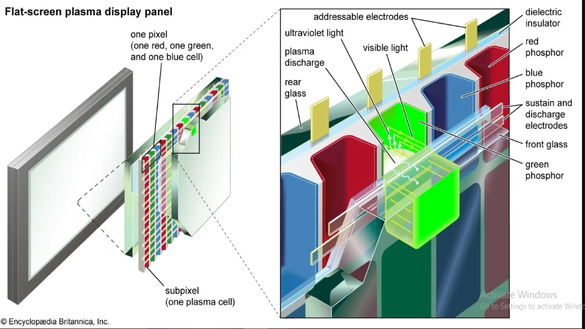
• Plasma Panel Display:
• Plasma-Panels are also called as Gas-Discharge Display. It consists of an
array of small lights. Lights are fluorescent in nature.
26.
The essential componentsof the plasma-panel display are:
Cathode: It consists of fine wires. It delivers negative voltage to gas cells. The voltage is released along with the
negative axis.
Anode: It also consists of line wires. It delivers positive voltage. The voltage is supplied along positive axis.
Fluorescent cells: It consists of small pockets of gas liquids when the voltage is applied to this liquid (neon gas) it
emits light.
Glass Plates: These plates act as capacitors. The voltage will be applied, the cell will glow continuously. The gas will
slow when there is a significant voltage difference between horizontal and vertical wires. The voltage level is kept
between 90 volts to 120 volts. Plasma level does not require refreshing. Erasing is done by reducing the voltage to
90 volts.
Each cell of plasma has two states, so cell is said to be stable. Displayable point in plasma panel is made by the
crossing of the horizontal and vertical grid. The resolution of the plasma panel can be up to 512 * 512 pixels.
Advantage:
High Resolution
Large screen size is also possible.
Less Volume
Less weight
Flicker Free Display
Disadvantage:
Poor Resolution
Wiring requirement anode and the cathode is complex.
Its addressing is also complex.
27.
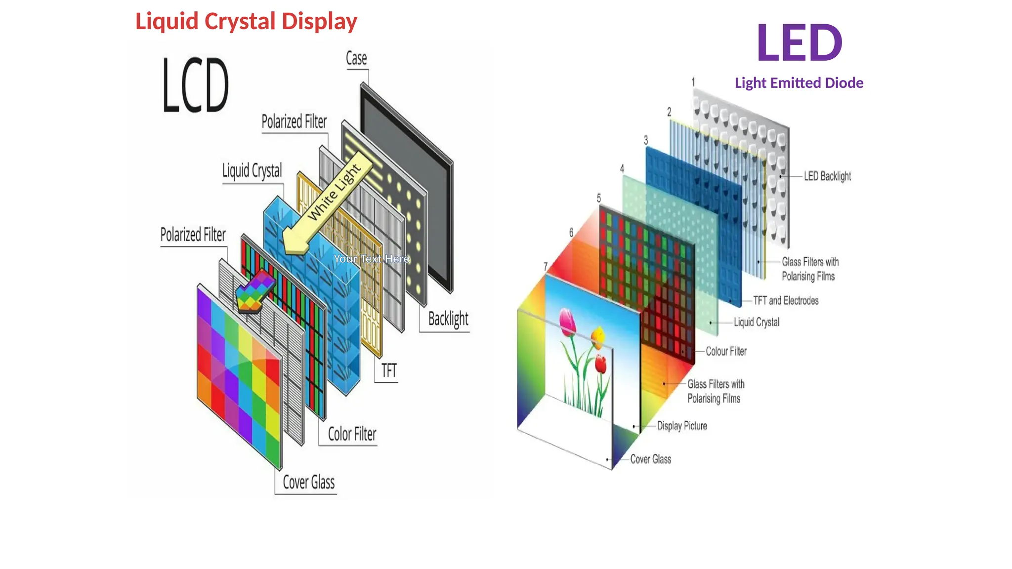
LED(Light Emitting Diode):
–In an LED, a matrix of diodes is organized to form the pixel positions in the display and picture
definition is stored in a refresh buffer. Data is read from the refresh buffer and converted to voltage
levels that are applied to the diodes to produce the light pattern in the display.
– LCD (Liquid Crystal Display):Liquid Crystal Displays are the devices that produce a picture by
passing polarized light from the surroundings or from an internal light source through a liquid-crystal
material that transmits the light.
– LCD uses the liquid-crystal material between two glass plates; each plate is the right angle to each
other between plates liquid is filled. One glass plate consists of rows of conductors arranged in
vertical direction. Another glass plate is consisting of a row of conductors arranged in horizontal
direction. The pixel position is determined by the intersection of the vertical & horizontal conductor.
This position is an active part of the screen.
– Liquid crystal display is temperature dependent. It is between zero to seventy degree Celsius. It is flat
and requires very little power to operate.
Advantage:
Low power consumption.
Small Size
Low Cost
Disadvantage:
LCDs are temperature-dependent(0-70°C)
LCDs do not emit light; as a result, the image has very little contrast.
LCDs have color capability.
There solution is not as good as that of a CRT.
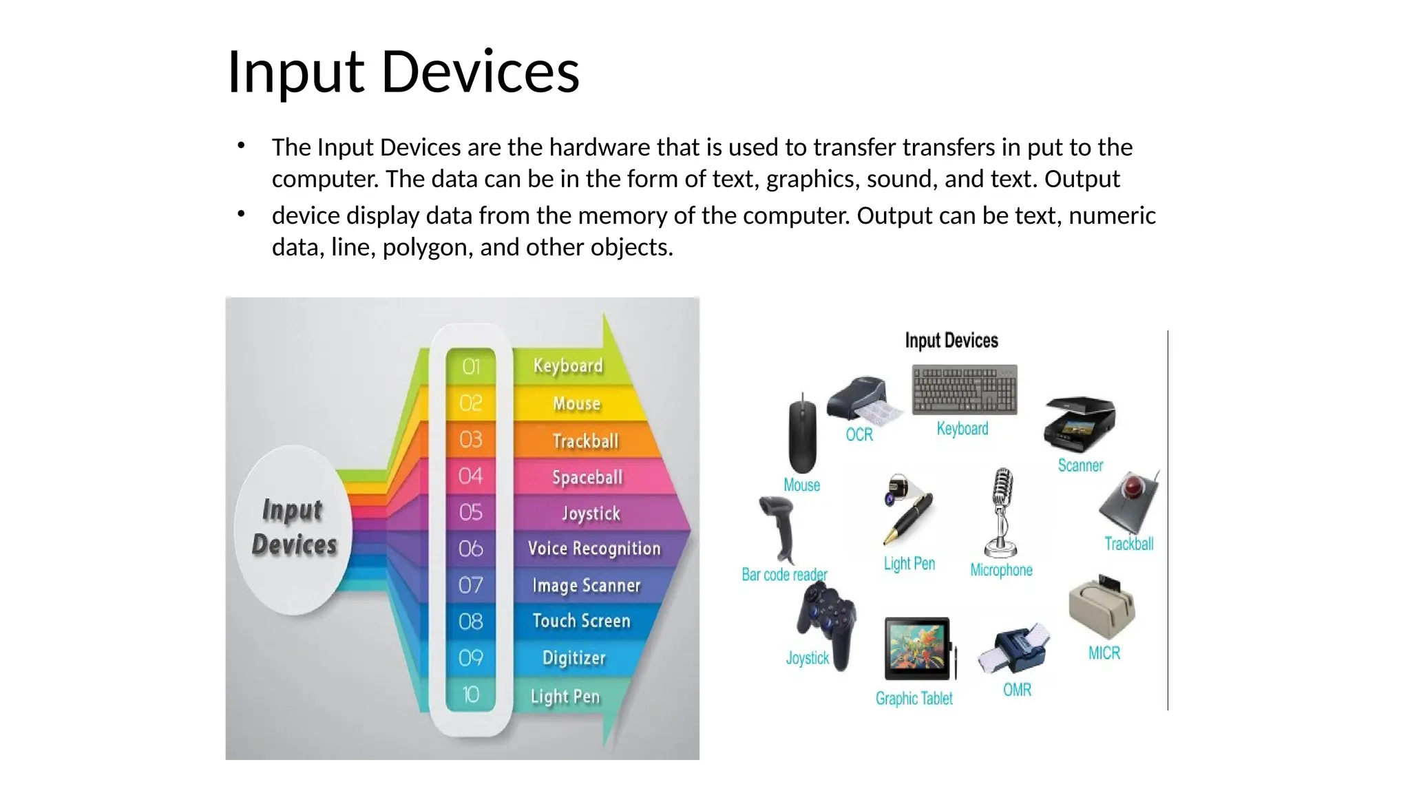
Input Devices
• TheInput Devices are the hardware that is used to transfer transfers in put to the
computer. The data can be in the form of text, graphics, sound, and text. Output
• device display data from the memory of the computer. Output can be text, numeric
data, line, polygon, and other objects.
32.
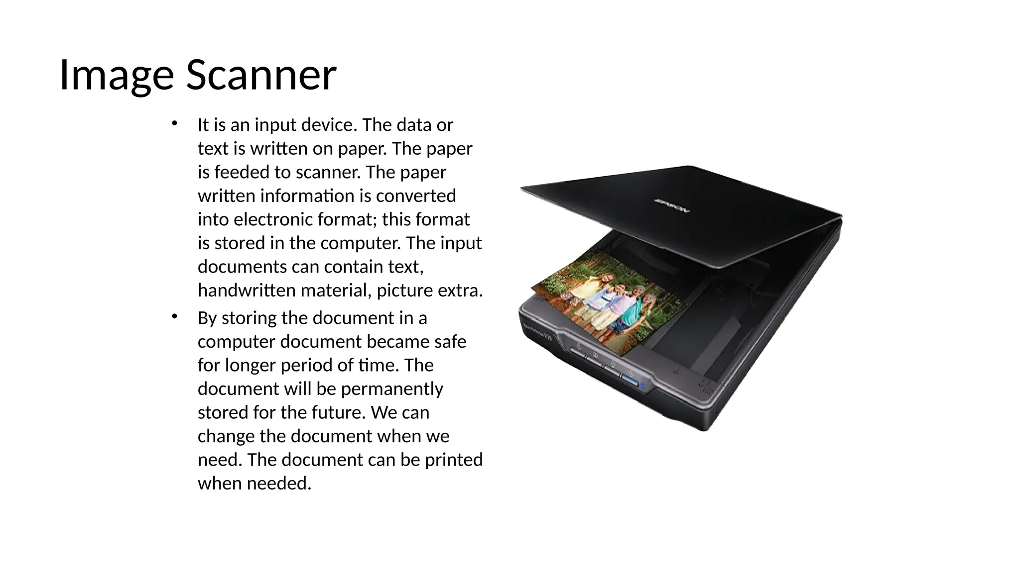
Image Scanner
• Itis an input device. The data or
text is written on paper. The paper
is feeded to scanner. The paper
written information is converted
into electronic format; this format
is stored in the computer. The input
documents can contain text,
handwritten material, picture extra.
• By storing the document in a
computer document became safe
for longer period of time. The
document will be permanently
stored for the future. We can
change the document when we
need. The document can be printed
when needed.
33.
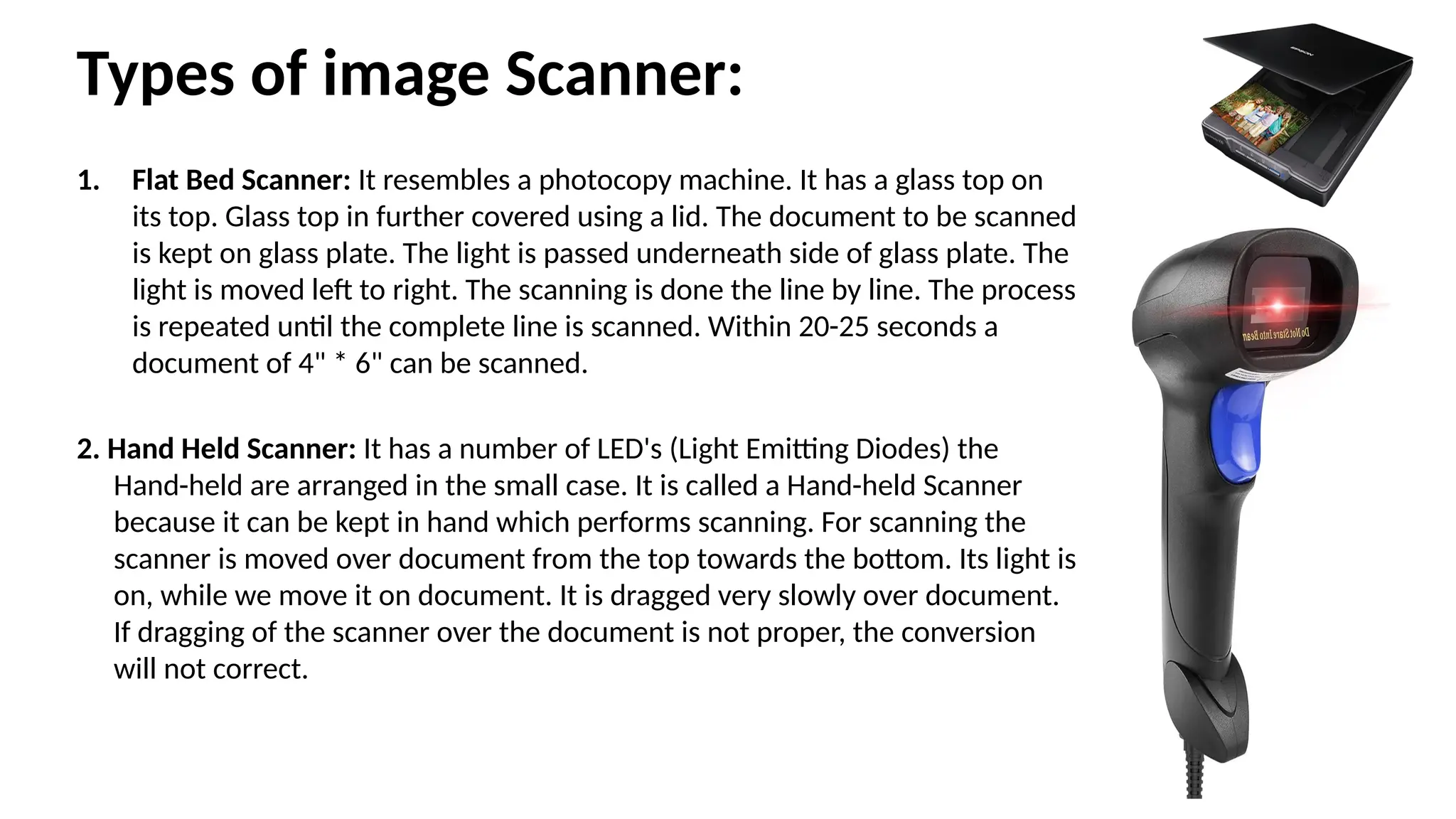
Types of imageScanner:
1. Flat Bed Scanner: It resembles a photocopy machine. It has a glass top on
its top. Glass top in further covered using a lid. The document to be scanned
is kept on glass plate. The light is passed underneath side of glass plate. The
light is moved left to right. The scanning is done the line by line. The process
is repeated until the complete line is scanned. Within 20-25 seconds a
document of 4" * 6" can be scanned.
2. Hand Held Scanner: It has a number of LED's (Light Emitting Diodes) the
Hand-held are arranged in the small case. It is called a Hand-held Scanner
because it can be kept in hand which performs scanning. For scanning the
scanner is moved over document from the top towards the bottom. Its light is
on, while we move it on document. It is dragged very slowly over document.
If dragging of the scanner over the document is not proper, the conversion
will not correct.
34.
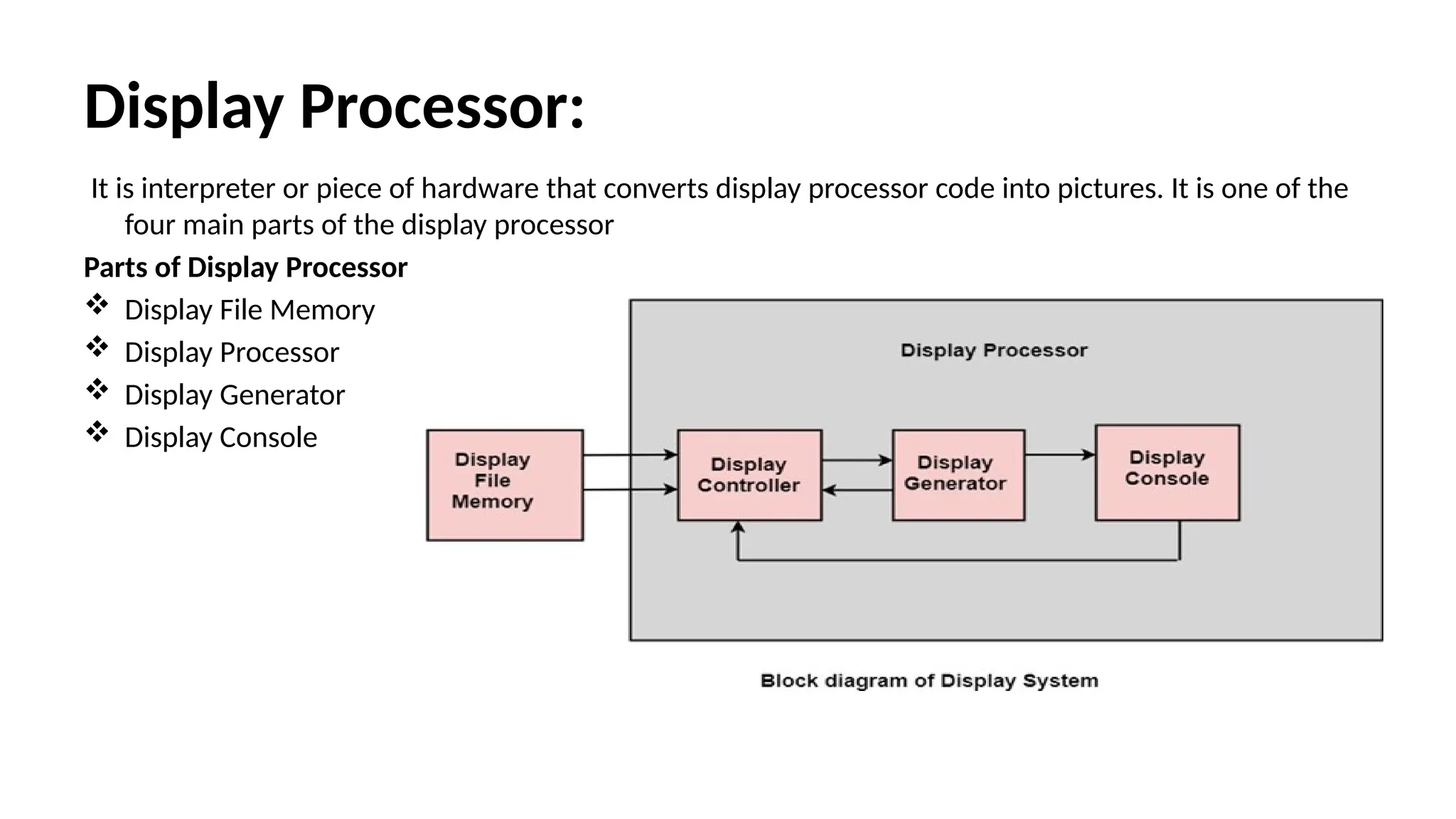
Display Processor:
It isinterpreter or piece of hardware that converts display processor code into pictures. It is one of the
four main parts of the display processor
Parts of Display Processor
Display File Memory
Display Processor
Display Generator
Display Console
35.
Parts of DisplayProcessor
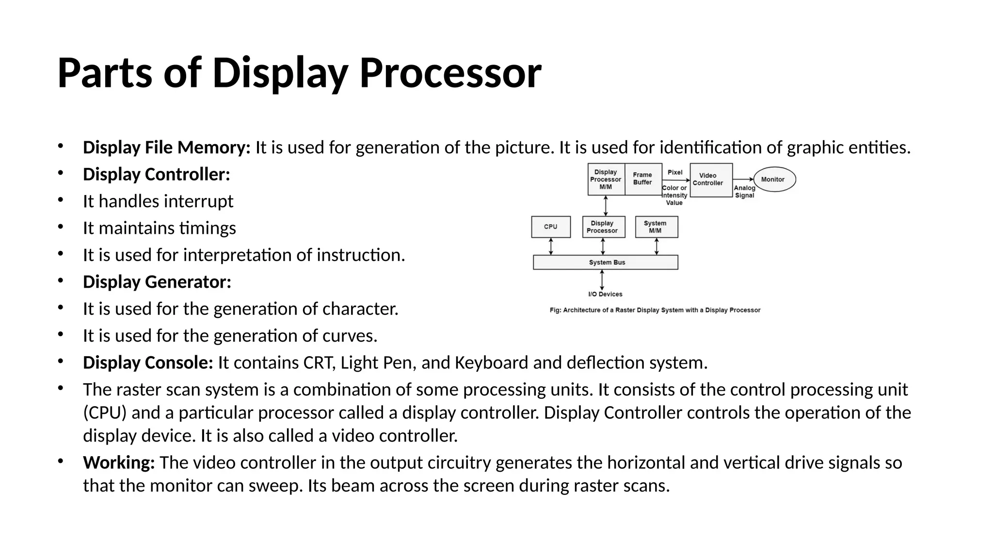
• Display File Memory: It is used for generation of the picture. It is used for identification of graphic entities.
• Display Controller:
• It handles interrupt
• It maintains timings
• It is used for interpretation of instruction.
• Display Generator:
• It is used for the generation of character.
• It is used for the generation of curves.
• Display Console: It contains CRT, Light Pen, and Keyboard and deflection system.
• The raster scan system is a combination of some processing units. It consists of the control processing unit
(CPU) and a particular processor called a display controller. Display Controller controls the operation of the
display device. It is also called a video controller.
• Working: The video controller in the output circuitry generates the horizontal and vertical drive signals so
that the monitor can sweep. Its beam across the screen during raster scans.
36.
Video Controller
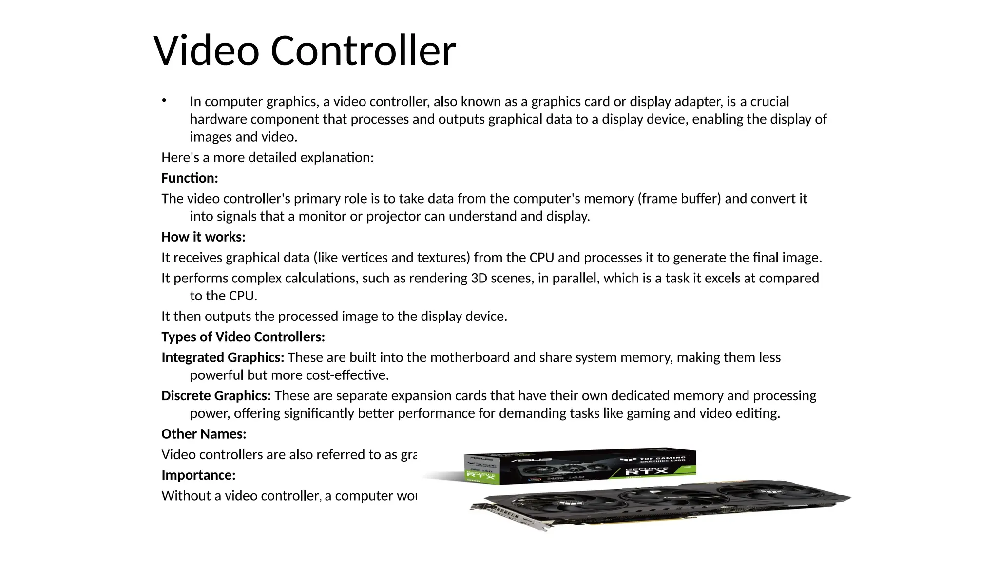
• Incomputer graphics, a video controller, also known as a graphics card or display adapter, is a crucial
hardware component that processes and outputs graphical data to a display device, enabling the display of
images and video.
Here's a more detailed explanation:
Function:
The video controller's primary role is to take data from the computer's memory (frame buffer) and convert it
into signals that a monitor or projector can understand and display.
How it works:
It receives graphical data (like vertices and textures) from the CPU and processes it to generate the final image.
It performs complex calculations, such as rendering 3D scenes, in parallel, which is a task it excels at compared
to the CPU.
It then outputs the processed image to the display device.
Types of Video Controllers:
Integrated Graphics: These are built into the motherboard and share system memory, making them less
powerful but more cost-effective.
Discrete Graphics: These are separate expansion cards that have their own dedicated memory and processing
power, offering significantly better performance for demanding tasks like gaming and video editing.
Other Names:
Video controllers are also referred to as graphics cards, video adapters, video boards, or display adapters.
Importance:
Without a video controller, a computer would not be able to display any graphical output.
37.
Clipping
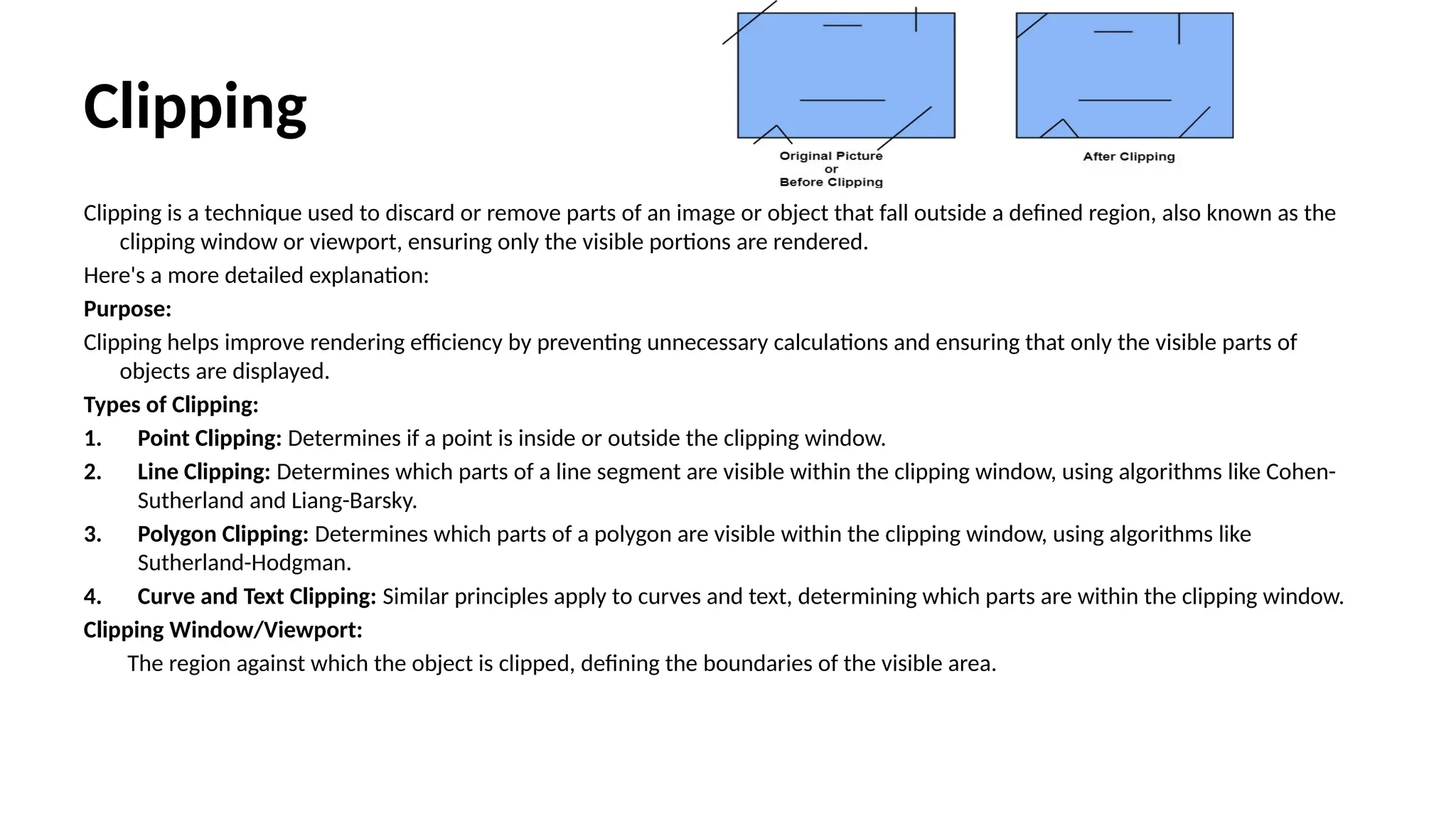
Clipping is atechnique used to discard or remove parts of an image or object that fall outside a defined region, also known as the
clipping window or viewport, ensuring only the visible portions are rendered.
Here's a more detailed explanation:
Purpose:
Clipping helps improve rendering efficiency by preventing unnecessary calculations and ensuring that only the visible parts of
objects are displayed.
Types of Clipping:
1. Point Clipping: Determines if a point is inside or outside the clipping window.
2. Line Clipping: Determines which parts of a line segment are visible within the clipping window, using algorithms like Cohen-
Sutherland and Liang-Barsky.
3. Polygon Clipping: Determines which parts of a polygon are visible within the clipping window, using algorithms like
Sutherland-Hodgman.
4. Curve and Text Clipping: Similar principles apply to curves and text, determining which parts are within the clipping window.
Clipping Window/Viewport:
The region against which the object is clipped, defining the boundaries of the visible area.
38.
Applications:
Applications:
Clipping is usedto display parts of a scene within a defined area, like a window on
a screen, and to improve rendering performance.
Algorithms:
1. Cohen-Sutherland: A line clipping algorithm that uses region codes to
determine if a line segment is entirely inside, outside, or intersects the
clipping window.
2. Liang-Barsky: Another line clipping algorithm that uses parametric
representation of lines to efficiently determine if a line segment lies inside
the clipping window.
3. Sutherland-Hodgeman: A polygon clipping algorithm that iteratively clips a
polygon against the edges of the clipping window.
4. Cyrus-Beck: A line clipping algorithm that uses parametric line representation
and dot products to efficiently determine if a line segment lies inside the
clipping window.
39.
Cohen-Sutherland
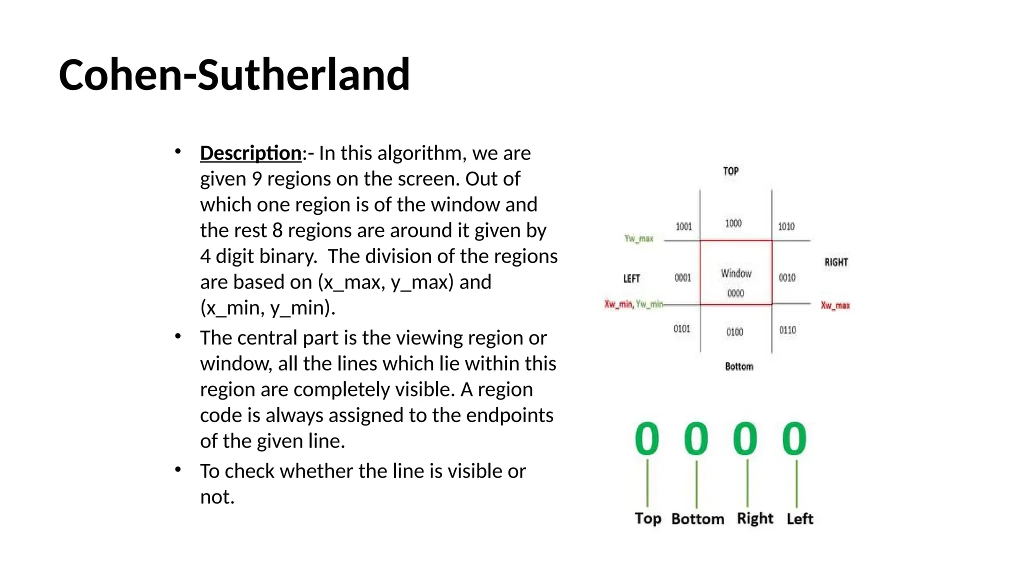
• Description:- Inthis algorithm, we are
given 9 regions on the screen. Out of
which one region is of the window and
the rest 8 regions are around it given by
4 digit binary. The division of the regions
are based on (x_max, y_max) and
(x_min, y_min).
• The central part is the viewing region or
window, all the lines which lie within this
region are completely visible. A region
code is always assigned to the endpoints
of the given line.
• To check whether the line is visible or
not.
40.
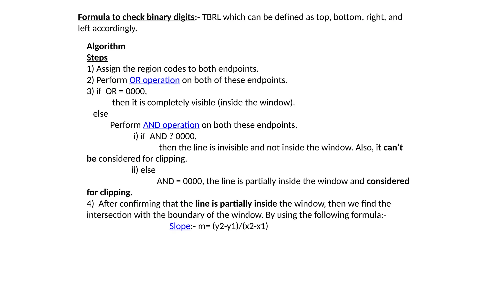
Formula to checkbinary digits:- TBRL which can be defined as top, bottom, right, and
left accordingly.
Algorithm
Steps
1) Assign the region codes to both endpoints.
2) Perform OR operation on both of these endpoints.
3) if OR = 0000,
then it is completely visible (inside the window).
else
Perform AND operation on both these endpoints.
i) if AND ? 0000,
then the line is invisible and not inside the window. Also, it can’t
be considered for clipping.
ii) else
AND = 0000, the line is partially inside the window and considered
for clipping.
4) After confirming that the line is partially inside the window, then we find the
intersection with the boundary of the window. By using the following formula:-
Slope:- m= (y2-y1)/(x2-x1)
41.
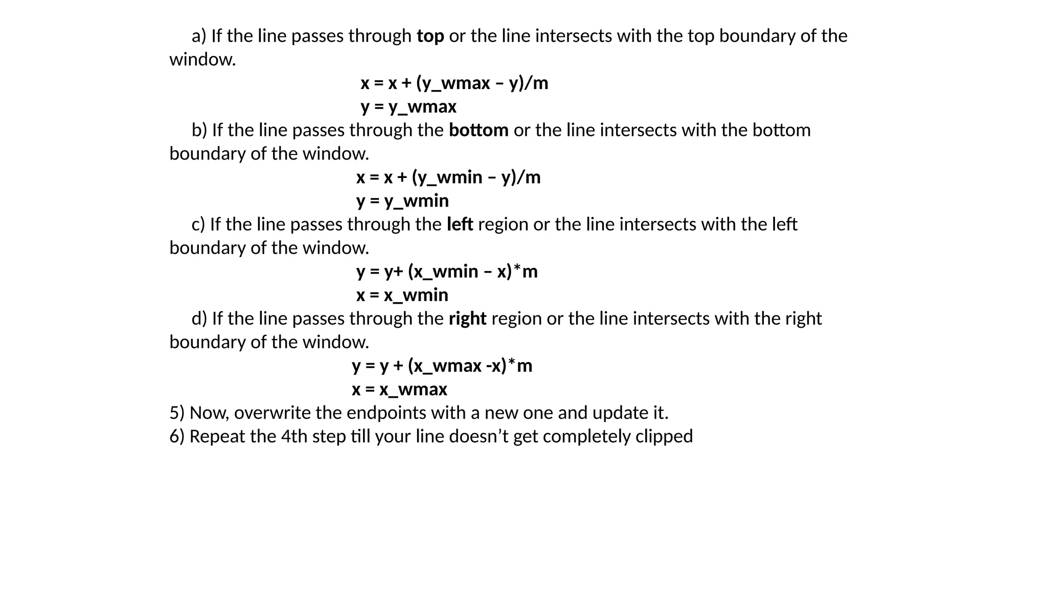
a) If theline passes through top or the line intersects with the top boundary of the
window.
x = x + (y_wmax – y)/m
y = y_wmax
b) If the line passes through the bottom or the line intersects with the bottom
boundary of the window.
x = x + (y_wmin – y)/m
y = y_wmin
c) If the line passes through the left region or the line intersects with the left
boundary of the window.
y = y+ (x_wmin – x)*m
x = x_wmin
d) If the line passes through the right region or the line intersects with the right
boundary of the window.
y = y + (x_wmax -x)*m
x = x_wmax
5) Now, overwrite the endpoints with a new one and update it.
6) Repeat the 4th step till your line doesn’t get completely clipped
42.
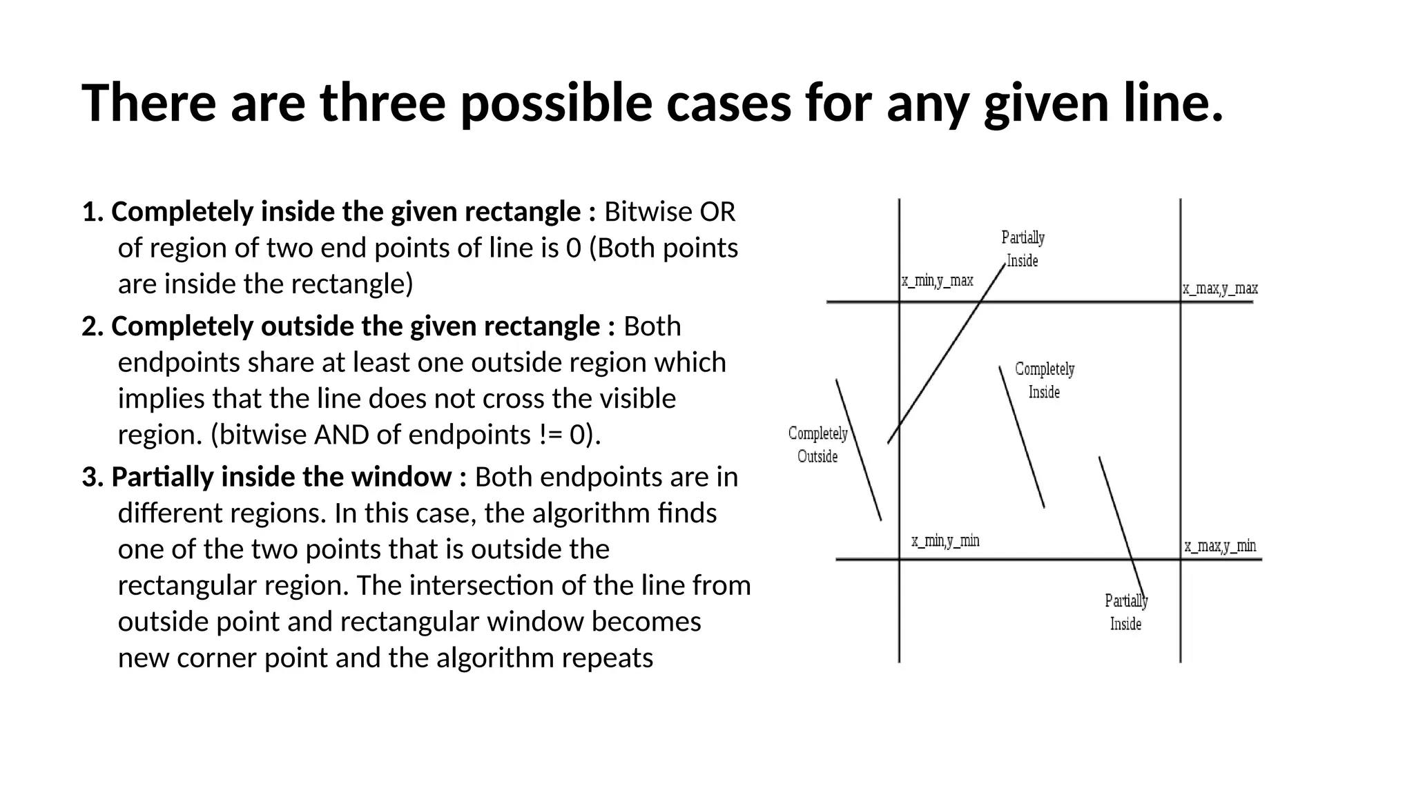
There are threepossible cases for any given line.
1. Completely inside the given rectangle : Bitwise OR
of region of two end points of line is 0 (Both points
are inside the rectangle)
2. Completely outside the given rectangle : Both
endpoints share at least one outside region which
implies that the line does not cross the visible
region. (bitwise AND of endpoints != 0).
3. Partially inside the window : Both endpoints are in
different regions. In this case, the algorithm finds
one of the two points that is outside the
rectangular region. The intersection of the line from
outside point and rectangular window becomes
new corner point and the algorithm repeats
43.
Cyrus Beck AlgorithmLine Clipping
• Cyrus Beck is a line clipping algorithm that is made for convex polygons. It
allows line clipping for non-rectangular windows, unlike Cohen Sutherland
. It also removes the repeated clipping needed in Cohen Sutherland.
• Input:
1. Convex area of interest which is defined by a set of coordinates given in a
clockwise fashion.
2. vertices which are an array of coordinates: consisting of pairs (x, y)
3. n which is the number of vertices
4. A line to be clipped given by a set of coordinates. 5. line which is an array
of coordinates: consisting of two pairs, (x0, y0) and (x1, y1)
Output:
1. Coordinates of line clipping which is the Accepted clipping
2. 2. Coordinates (-1, -1) which is the Rejected clipping
44.
Algorithm:
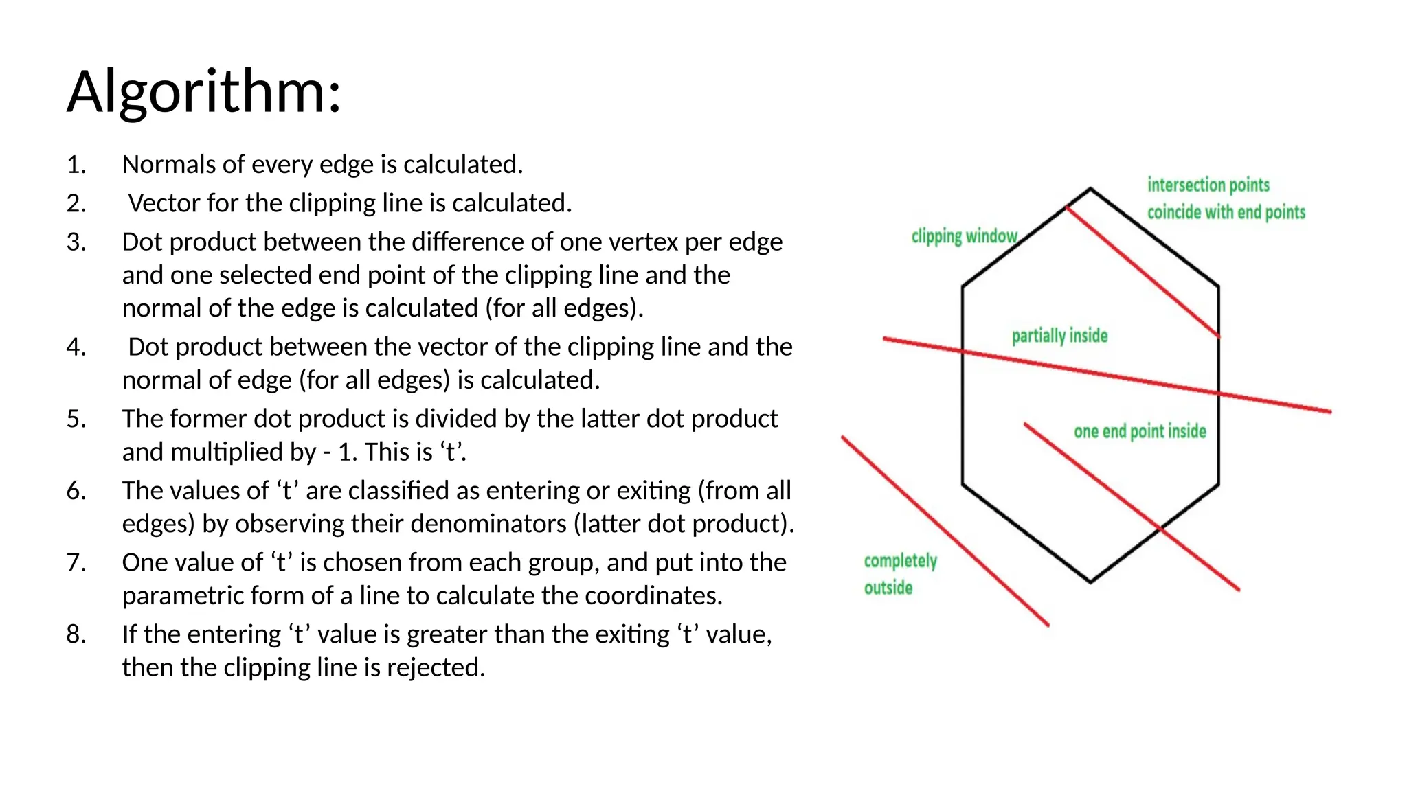
1. Normals ofevery edge is calculated.
2. Vector for the clipping line is calculated.
3. Dot product between the difference of one vertex per edge
and one selected end point of the clipping line and the
normal of the edge is calculated (for all edges).
4. Dot product between the vector of the clipping line and the
normal of edge (for all edges) is calculated.
5. The former dot product is divided by the latter dot product
and multiplied by - 1. This is ‘t’.
6. The values of ‘t’ are classified as entering or exiting (from all
edges) by observing their denominators (latter dot product).
7. One value of ‘t’ is chosen from each group, and put into the
parametric form of a line to calculate the coordinates.
8. If the entering ‘t’ value is greater than the exiting ‘t’ value,
then the clipping line is rejected.
45.
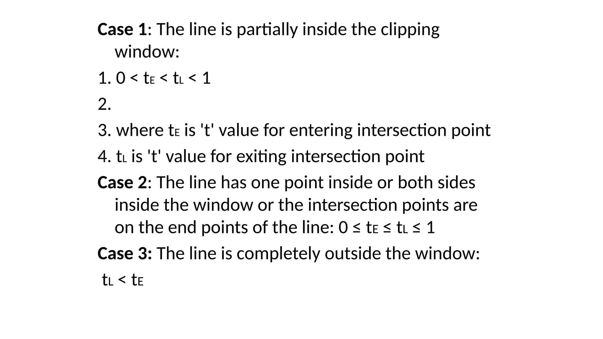
Case 1: Theline is partially inside the clipping
window:
1. 0 < tE < tL < 1
2.
3. where tE is 't' value for entering intersection point
4. tL is 't' value for exiting intersection point
Case 2: The line has one point inside or both sides
inside the window or the intersection points are
on the end points of the line: 0 ≤ tE ≤ tL ≤ 1
Case 3: The line is completely outside the window:
tL < tE
46.
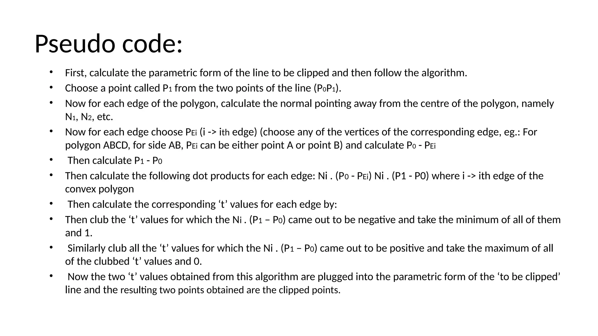
Pseudo code:
• First,calculate the parametric form of the line to be clipped and then follow the algorithm.
• Choose a point called P1 from the two points of the line (P0P1).
• Now for each edge of the polygon, calculate the normal pointing away from the centre of the polygon, namely
N1, N2, etc.
• Now for each edge choose PEi (i -> ith edge) (choose any of the vertices of the corresponding edge, eg.: For
polygon ABCD, for side AB, PEi can be either point A or point B) and calculate P0 - PEi
• Then calculate P1 - P0
• Then calculate the following dot products for each edge: Ni . (P0 - PEi) Ni . (P1 - P0) where i -> ith edge of the
convex polygon
• Then calculate the corresponding ‘t’ values for each edge by:
• Then club the ‘t’ values for which the Ni . (P1 – P0) came out to be negative and take the minimum of all of them
and 1.
• Similarly club all the ‘t’ values for which the Ni . (P1 – P0) came out to be positive and take the maximum of all
of the clubbed ‘t’ values and 0.
• Now the two ‘t’ values obtained from this algorithm are plugged into the parametric form of the ‘to be clipped’
line and the resulting two points obtained are the clipped points.