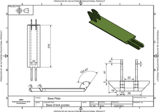
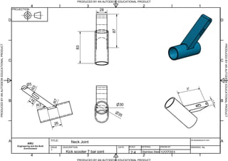
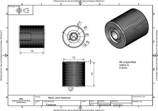
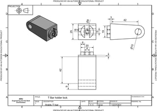
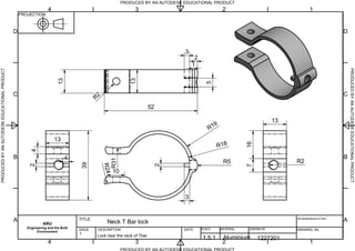
The document provides details on the design and assembly of a kids' kick scooter using Autodesk Inventor software. It includes summaries of the key steps: part designs were created using 2D sketches, extrusion, fillets, holes, and other tools; parts were assembled using mating and constraints; presentations and animations were created; and 2D projections including drawings, dimensions, and balloons were generated. The summary concludes the report provides an overview of complex design generation, assembly, and design constraints using Inventor.
Designing paper straw bridge (lightest at ARU - 2.1g). Designing in inventor, Finite Element Modelling and Analysis - ANSYS , Stiffness matrix and constructing a final product.
Adaptive Control strategies helps to get desirable output for system with partial unknown dynamics or systems having unknown and unmodeled load variation. DC servo motors are useful to track rapid speed trajectory for various applications, particularly with need of high starting torque and low inertia. Model Reference Adaptive Control (MRAC) parameter data of results with Lyapunov stability MRAC has been used to generate adaptation parameter for DC motor speed controller.
Finite element analysis of center pin and bracket of jig fixture assembly ijm...Dr.Vikas Deulgaonkar
The manufacturing industry caters the range of products to satisfy the ever changing market needs.
To overcome the increasing production demands, the industry implies various techniques. We need a technique for
increasing the production of drilling two holes on a Railway Pinion, improve the quality of product and reduce the
operation time. This project aims to design the Jig and Fixture for the same. The 3-dimensional Computer Aided Model
of the components is made using CATIA V5-R21 software. To study the behavior of component, simulation is carried out.
Preprocessing of the CAD model is carried in Hypermesh software. Boundary conditions are applied using physical
situations of the components. Finite element analysis of the components is done, and the results obtained are compared
with the theoretical analysis and also with the available literature. The stresses and deformations are found within desired limits. Using FE analysis, the parts are manufactured and assembled.
COMPUTATIONAL ENGINEERING OF FINITE ELEMENT MODELLING FOR AUTOMOTIVE APPLICAT...IAEME Publication
Modals with complicated geometry, complex loads and boundary condition are difficult to analyse and evaluate in the terms of strain, stress, displacement and reaction forces by using theoretical methods. A given modal can be analysed by using Finite Element Method easily with the help of computer software ABAQUS CAE and can get approximate solutions. This report is about modelling two dimensional and three dimensional analyses with the ABAQUS CAE for plane stress, plane strain, shell, and beam and 3d solid modal elements.
IJRET : International Journal of Research in Engineering and Technology is an international peer reviewed, online journal published by eSAT Publishing House for the enhancement of research in various disciplines of Engineering and Technology. The aim and scope of the journal is to provide an academic medium and an important reference for the advancement and dissemination of research results that support high-level learning, teaching and research in the fields of Engineering and Technology. We bring together Scientists, Academician, Field Engineers, Scholars and Students of related fields of Engineering and Technology
Finite element optimization of stator by casted and welded structureseSAT Publishing House
IJRET : International Journal of Research in Engineering and Technology is an international peer reviewed, online journal published by eSAT Publishing House for the enhancement of research in various disciplines of Engineering and Technology. The aim and scope of the journal is to provide an academic medium and an important reference for the advancement and dissemination of research results that support high-level learning, teaching and research in the fields of Engineering and Technology. We bring together Scientists, Academician, Field Engineers, Scholars and Students of related fields of Engineering and Technology
Simulation of Deep-Drawing Process of Large Panelstheijes
The article deals with the analysis of formability of deep-drawing DC06 steel sheets. The aim of the investigations is to verify possibilities of formability of sheet metal with thickness of 0.85 mm. The mechanical parameters of the sheets have been determined in uniaxial tensile and bulge tests. The numerical simulations using AUTOFORM has been carried out for two drawpiece models. Obtained results can be used during the simulation of real forming process.
Operations management in business assignment sampleElite Assignment
Here is the an assignment writing help sample on operations management, this should help writing an assignment and learning to write an assignment on this topic.
Automatic Computer-Aided Design (AutoCAD 2D) engineering drawing is an important
component in BFPD courses. This software is commonly practiced by students for the product
design process as part of the project development. However, there is a lack of quality in 2D
engineering drawing that affects the students’ prototype making process and project progression.
This paper intends to identify the problems that weakened the students' performances of the
AutoCAD 2D engineering drawings. Data were collected from the students’ examinations,
assignments, and independent projects. Semi-structured interviews were also conducted with the
students.
Top 5 Indian Style Modular Kitchen DesignsFinzo Kitchens
Get the perfect modular kitchen in Gurgaon at Finzo! We offer high-quality, custom-designed kitchens at the best prices. Wardrobes and home & office furniture are also available. Free consultation! Best Quality Luxury Modular kitchen in Gurgaon available at best price. All types of Modular Kitchens are available U Shaped Modular kitchens, L Shaped Modular Kitchen, G Shaped Modular Kitchens, Inline Modular Kitchens and Italian Modular Kitchen.
Between Filth and Fortune- Urban Cattle Foraging Realities by Devi S Nair, An...Mansi Shah
This study examines cattle rearing in urban and rural settings, focusing on milk production and consumption. By exploring a case in Ahmedabad, it highlights the challenges and processes in dairy farming across different environments, emphasising the need for sustainable practices and the essential role of milk in daily consumption.
White wonder, Work developed by Eva TschoppMansi Shah
White Wonder by Eva Tschopp
A tale about our culture around the use of fertilizers and pesticides visiting small farms around Ahmedabad in Matar and Shilaj.
Can AI do good? at 'offtheCanvas' India HCI preludeAlan Dix
Invited talk at 'offtheCanvas' IndiaHCI prelude, 29th June 2024.
https://www.alandix.com/academic/talks/offtheCanvas-IndiaHCI2024/
The world is being changed fundamentally by AI and we are constantly faced with newspaper headlines about its harmful effects. However, there is also the potential to both ameliorate theses harms and use the new abilities of AI to transform society for the good. Can you make the difference?
Dive into the innovative world of smart garages with our insightful presentation, "Exploring the Future of Smart Garages." This comprehensive guide covers the latest advancements in garage technology, including automated systems, smart security features, energy efficiency solutions, and seamless integration with smart home ecosystems. Learn how these technologies are transforming traditional garages into high-tech, efficient spaces that enhance convenience, safety, and sustainability.
Ideal for homeowners, tech enthusiasts, and industry professionals, this presentation provides valuable insights into the trends, benefits, and future developments in smart garage technology. Stay ahead of the curve with our expert analysis and practical tips on implementing smart garage solutions.
Hello everyone! I am thrilled to present my latest portfolio on LinkedIn, marking the culmination of my architectural journey thus far. Over the span of five years, I've been fortunate to acquire a wealth of knowledge under the guidance of esteemed professors and industry mentors. From rigorous academic pursuits to practical engagements, each experience has contributed to my growth and refinement as an architecture student. This portfolio not only showcases my projects but also underscores my attention to detail and to innovative architecture as a profession.
2. Table of Contents
Contents Leaf No.
Introduction 1
Literature Review 1
PDS 1
Method 1
Part Design 2
2D Sketch
Trim
Extend
Extrude
Fillet 3
Hole 4
Circular Pattern
Loft
Work Planes 5
Ribs
Sweep 6
Coil
Thread
Assembly 6
Mate or Flush 7
Presentation 8
Animate 9
2D Projections 9
Conclusion 12
References 13
2D Presentations blue print 14
3. 1
Introduction:
Every successful product that is in world market has to go on basic generation of concept designing. In the 19th Century
and early 20th the engineers used to the sets of 2D drafters to draw a projection of their ideal drawing. Things have
changed in the modern era. Much of the anticipated products that are launched have to go under the rigorous development
in the designing software’s. One of this most widely used software is Inventor, from Auto Desk. The report is on a kid Kick
scooter designed on the inventor. The designs are made on the 2D sketch. There have been multiple tools used to get the
product live and robust in look. The multiple applications include the extrusion, filleting the sharp edges, using and moving
the profile plane, mirroring the same products, projections, using a swap and loop to create typical complicated parts.
Every part has been separately designed and final product has been assembled. The product has been explained in the 2D
charts with ballooning every minute detail highlighted along with the presentation and the explosion video.
By the end, the report shall give us a brief idea about the generation of complex designs, assembling and the constraints of
designing.
Literature Review:
Inventor offers a range of the library functions and tools to design produce and animate
the product. Whilst the user can change the preference of the materials and structural
appearance it offers one click function to complete the function.
The Kids' Kick Scooter is one such product designed by the user. It is a playful kit for the
children especially for the age group 7 -13 ages of years. The user has made the product
out of assembling 18 small parts excluding the fasteners and the rib-bets. The user has
provided PDS to explain the product's specifications.
Figure 0 (Right) : Kids Kick Scooter
PDS -
Features Dimensions.
Detailed Specification Ages: 3-5
Wheel Size: 120mm
Wheel Material: Hard Rubber (PU)
Storage: TBar is fold able
Weight: 44lbs
Length/width of scooter 21" x 4.5"
Length/width of standing
deck
12 x 4.5"
The product has an age restriction of 5 years of above. For the ease of the use and manufacture the user has opted to use
the combination of Aluminium, Stainless steel, Plastic covers and use of rubber as the raw material for the product. The
product can be easily manufactured by a CNC machine and using standard process of manufacture – machining, drilling,
facing and injection moulding.
Method:
The whole product is assembled out of 18 important parts and rounding of roughly 22 small parts together. The vivid
steps involved are described with their images and the steps involved in it.
1. Part Designs 2. Assembly or Parts Assembly 3. Presentation 4. Animate
5. 2D presentation and projections
4. 2
Part Work PlanesDesigns:
2d Sketch- Every design starts with the two sketches. The user needs to select one of the planes out of the X,Y& Z. With
basic geometrical application the sketch is completed as drawn on sheet. These include, line, arc (multiple options : arc
with three points, arc with two points and many more), rectangle, circle with centre and etc. All the sketches were fully
constrained as shown in the figure 1.
Figure 1 – Shows the 2D Sketch of the neck lock of the scooter
Trim – An important aspect of the 2D drawing is the option of trim. This allows to delete the extended sketches that is not
needed
Extend – The option allows the user to connect by extending the area of the sketch up to the desired point.
Extrude – This allows giving a solid shape to the 2D figure sketched earlier in the step. The dimensions are fed along with
the option of symmetric/ throughout the length. Demonstrated on Figure 2,3 & 4.
Figure 2: Extrude of the 2D sketch
Figure 3: Extrude to create hollow
5. 3
Figure 4: Completed extrusion.
Fillet – To smoother the edges the fillet option is used. A variable fillet can be used on the specified edge and length. The
user can even feed the intermediate points to get variable radius. The image below shows filleting
Figure 5: Filleting of the sharp corner of the design
6. 4
Hole – It is a 3D application to create a hole pattern as per the user fed. Generally used for a drill and other factor
applications.
Figure 6:
Creating a hole
Circular Pattern – It is the creation of the solid feature. The user needs to feed the angle and dimension. Figure 7.
Figure 7: Creating a circular pattern.
Loft – The loft application gives the user the freedom to draw on two different work planes and merge them together. It
has variable sketched residing on two different planes can used together in this function shown in figure 8
7. 5
Figure 8: Creating a circular pattern.
Work Planes – Construction of the sketches on complex or beyond origin needs to assign an artificial plane as reference
called the work planes as shown in figure 9.
Figure 9: Using an artificial work plane.
Ribs – Ribs are the thin wall support shapes which can be created on the open or closed profile. Thickness of ribs planar to
the sketch can be fed by the user. The constructed thickness can be specified and projected. Illustrated on figure 10.
8. 6
Figure 10: Illustrating the use of ribs to generate lock structure.
Sweep - Construction of the sweep solid feature requires two sketches a profile sketch and a path sketch to specify the
path of the sweep operation. In a 3D sweep feature, the path is three dimensional.
Coil- The coil offers the user a a helical spring like structural feature. The specific parameters of the coils starting and ends
can be fed.
Thread- This allows the user, to simulate the appearance of threads on the curved surfaces of either a cylinder or a hole.
The only important parameter is that the dimensions and the diameter should match. Displayed on figure 11.
Figure 11: Below demonstrating the thread creation in inventor
Assembly:
Assembling products is quiet simple operation. These allow to constraint the user’s product and look like live. To assemble
the user needs to open the inventor and change the operation to standard (mm).iam. To place the parts, it is essential to
click on place and have all the standard parts in the same work place. This eases the use of operation and allows user to
quickly sort the design assemble.
9. 7
Clicking the parts selects them and places them. In a typical modelling process, some component designs are known and
some standard components are used. Create the designs to meet specific objectives. Refer figure 12 below
Figure 12: Displaying how to use the option of assembly
Assembly constraints establish the orientation of the components in the assembly and simulate mechanical relationships
between components. It can be done in the following ways:
Mating two planes.
Specify that cylindrical features on two parts remain concentric.
Constrain a spherical face on one component to remain tangent to a planar face on another component.
Each time the user updates the assembly, the assembly constraints are enforced.
Mate or Flush - when using origin planes to position a part, user needs to know that the final constraint will need to be
either a mate or a flush. It is important to observe the selection vector previews to determine if user wants arrows
pointing towards each other (mate) or pointing in the same direction (flush).
10. 8
Step 1: Select the products and click on constraint. The user decides to phase the constraints first (Figure 13)
Figure 13: Using constrain with faces.
Step 2: As soon as the faces are constrained, the user feeds to align it in to axis.
Step 3: The scooter handle with the side guards are ready on design. (Refer figure 14)
Figure 14: Using constraint along with Axis.
Presentation: (Refer Figure 15)
User can create a presentation document using the default template or a custom template. Presentation templates set the
file properties for assembly presentations.
11. 9
Figure 15: Use of the presentation in Inventor.
Step 1 Click on your Inventor Icon, Click on New, and Click on Presentation.
Step 2 Click on Create View, Open the folder Icon, and Find your Assemble file.
Step 3 Click Tweak Components.
Step 4 Select your IPT or Sub-assemblies from your browser window.
Step 5 Click on the surface of the part you want to move and place it.
Animate: (Figure 16)
Animation is the final stage of the design.
By clicking animation the assembly of
each component can be watched. Each
sequence is shown in a list. The camera
angles can be changed and alter a
sequence view which enables to focus on
a particular part being assembled.
Figure 16: Use of animation with camera
angles.
2D Projections:
It include basic views, dimensions, part lists, balloons, hole table information, and so on. The following image shows an
automatically generated 2-D drawing. (Refer Figure 17)
12. 10
Figure 17: Use of the 2D projections.
The User can create drawings for all the product part models. The user can configure the drawing setting for it, including
the Sheet Format, Dimension Style, Centre Mark, and so on. You can export Drawing groups and their drawing settings to
other mould Design documents.
If automatically generated drawing documents are unsatisfactory even the user can modify drawings manually in the
Inventor Drawing environment.
Procedures to create a 2D projected views :
1. It needs to be confirmed if the version of the Inventor has the 2D template. The user needs to open the inventor in a
drawing template ie. .'.idw'.
2. The user should follow clicking the option on the toolbar – base and select the component from the specific folder. (refer
figure 18.
Figure 18: How to operate the function of 2D templete
13. 11
3. The user can select the product according to choice and place either as an orthogonal or isometric projection. The figure
below shows how to proceed in placing the drawing. Refer figure 19
Figure 19: Proper use of the projections.
4. Proper scaling and orientation can also be to change the zoom effect of the product if it is too small. The figure shows
below. Refer figure 21.
Figure 21: Use of the orientation.
5. To start with the 2D projections, it is preferable to start with the main explosion figure. The user can use the ballooning
to list the details of the products. As shown in the figure. Refer figure 22.
14. 12
Figure 22:
Use of the ballooning.
6. Subsequently the user can place the right or left view of the projection and then insert the dimensions to show the
measurements of the part products. The figure below shows the dimensions. Refer figure 23.
Figure 23: Use of the dimensioning.
7. Finally when the labelling is done the details are documented.
Conclusion:
With the study of the Inventor from Auto desk it is well clear that a product goes on vivid stages of designs where it is
presented tested and formulated on the computer. The module Computer aided solid designing helps the user to
understand the important aspects of designing, making 2D constrained drawings, extrusion, filleting, looping, creating
complex structures like ribs. No soon once the 2D drawing is made, the product can be illustrated with the 3D features of
animating and exploding the part view.
In a small line to brief up, designing is a important aspect of our lifestyle products without which an accurate design is
really hard to generate.
15. 13
References:
Lecturer Dilen, 2014. Vle. [Online]
Available at: http://vle.anglia.ac.uk/modules/2013/MOD002610/SEM2-A-1/Pages/Home3.aspx
[Accessed 3 April 2014].
Auto Desk, 2014. [Online]
Available at: http://help.autodesk.com/view/INVNTOR/2014/ENU/
[Accessed 4th April 2014]
Anon., n.d. IIT Delhi. [Online]
Available at: http://web.iitd.ac.in/~hirani/Inventor%20Notes.pdf
[Accessed 4 April 2014].
16. Parts List
PART NUMBERQTYITEM
kick scooter body11
kick scooter12
kick scooter frount part two13
wheel lock14
kick scooter brake15
tyre26
fastener27
Flip inside Handle28
handle corner cover29
handle210
Lock 1 ROD111
Lock 1112
ROD IN LOCK113
main handle114
neck joint115
screw116
NF E 25-109 - M6 x 40117
NF E 25-109 - M6 x 50118
NF E 25-109 - M4 x 40119
ANSI B18.3 - 10-24 UNC - 1.75120
BS EN 24 036 - M6221
BS EN 24 036 - M4122
ISO 4036 - M4123
PRODUCED BY AN AUTODESK EDUCATIONAL PRODUCT
PRODUCED BY AN AUTODESK EDUCATIONAL PRODUCTPRODUCEDBYANAUTODESKEDUCATIONALPRODUCT
PRODUCEDBYANAUTODESKEDUCATIONALPRODUCT
1
1
2
2
3
3
4
4
A A
B B
C C
D D
PROJECTION
ARU
Engineering and the Built
Environment
TITLE:
DESCRIPTION DATE: SCALE MATERIAL DRAWN BY
All dimensions in mm.
DRAWING No.ISSUE
1
Kids Kick Scooter
0.17:1 1227201 1Kick Scooter Explosion
19
7
14
10
9
15
3
12
13
22
1
11
4
2
21
6 17
16
8
23
20
18
5
17. PRODUCED BY AN AUTODESK EDUCATIONAL PRODUCT
PRODUCED BY AN AUTODESK EDUCATIONAL PRODUCTPRODUCEDBYANAUTODESKEDUCATIONALPRODUCT
PRODUCEDBYANAUTODESKEDUCATIONALPRODUCT
1
1
2
2
3
3
4
4
A A
B B
C C
D D
PROJECTION
ARU
Engineering and the Built
Environment
TITLE:
DESCRIPTION DATE: SCALE MATERIAL DRAWN BY
All dimensions in mm.
DRAWING No.ISSUE
1
9
415
19
316
122.43
8
5
10 58
22
3
22
Base Plate
Base of kick scooter 0.30 : 1 1227201Iron
18. PRODUCED BY AN AUTODESK EDUCATIONAL PRODUCT
PRODUCED BY AN AUTODESK EDUCATIONAL PRODUCTPRODUCEDBYANAUTODESKEDUCATIONALPRODUCT
PRODUCEDBYANAUTODESKEDUCATIONALPRODUCT
1
1
2
2
3
3
4
4
A A
B B
C C
D D
PROJECTION
ARU
Engineering and the Built
Environment
TITLE:
DESCRIPTION DATE: SCALE MATERIAL DRAWN BY
All dimensions in mm.
DRAWING No.ISSUE
1
30
35
83
14
28
5
R3
16
R7
26
R3
87
97
Neck Joint
Kick scooter T bar joint 2:4 Stainless Steel 1227201
19. PRODUCED BY AN AUTODESK EDUCATIONAL PRODUCT
PRODUCED BY AN AUTODESK EDUCATIONAL PRODUCTPRODUCEDBYANAUTODESKEDUCATIONALPRODUCT
PRODUCEDBYANAUTODESKEDUCATIONALPRODUCT
1
1
2
2
3
3
4
4
A A
B B
C C
D D
PROJECTION
ARU
Engineering and the Built
Environment
TITLE:
DESCRIPTION DATE: SCALE MATERIAL DRAWN BY
All dimensions in mm.
DRAWING No.ISSUE
1
4
5
6
8
13
7
1
13
0.19
15
15
All unspecified
radius is
0.5mm
Neck Joint fastener
Fastener 4:1 Aluminium 1227201
20. PRODUCED BY AN AUTODESK EDUCATIONAL PRODUCT
PRODUCED BY AN AUTODESK EDUCATIONAL PRODUCTPRODUCEDBYANAUTODESKEDUCATIONALPRODUCT
PRODUCEDBYANAUTODESKEDUCATIONALPRODUCT
1
1
2
2
3
3
4
4
A A
B B
C C
D D
PROJECTION
ARU
Engineering and the Built
Environment
TITLE:
DESCRIPTION DATE: SCALE MATERIAL DRAWN BY
All dimensions in mm.
DRAWING No.ISSUE
1
42
9
20
8
6
3
10
19
25
R10
5
8
42
3
T Bar holder lock
Holds T bar 1:1 Iron 1227201
21. PRODUCED BY AN AUTODESK EDUCATIONAL PRODUCT
PRODUCED BY AN AUTODESK EDUCATIONAL PRODUCTPRODUCEDBYANAUTODESKEDUCATIONALPRODUCT
PRODUCEDBYANAUTODESKEDUCATIONALPRODUCT
1
1
2
2
3
3
4
4
A A
B B
C C
D D
PROJECTION
ARU
Engineering and the Built
Environment
TITLE:
DESCRIPTION DATE: SCALE MATERIAL DRAWN BY
All dimensions in mm.
DRAWING No.ISSUE
1
R
2
5
1
2
3
13
13
52
4
39
13
42
R19
R18
R5
3
2
R31
R24
10
13
R2
716
Neck T Bar lock
Lock near the neck of Tbar
1.5:1 Aluminium 1227201