Download as PDF, PPTX
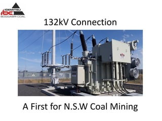


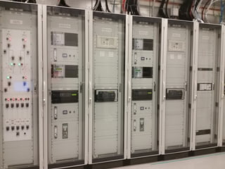
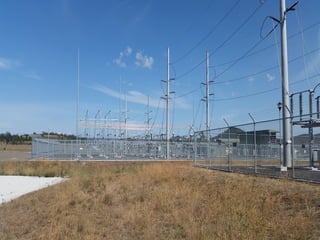


The 132kV transmission line connection to Boggabri Coal Operations was the first of its kind for a coal mine in NSW. It included a 15km transmission line, switching station, and substation to supply the mine's increased power demands of up to 8MVA. While innovative, the project faced challenges integrating the transmission-oriented design with the mine's operations. Collaboration between the transmission and mining industries was needed to address differences in design philosophies, protection schemes, and isolation procedures. Key outcomes included agreements on equipment isolation, communication protocols, and training to safely operate the shared infrastructure.


