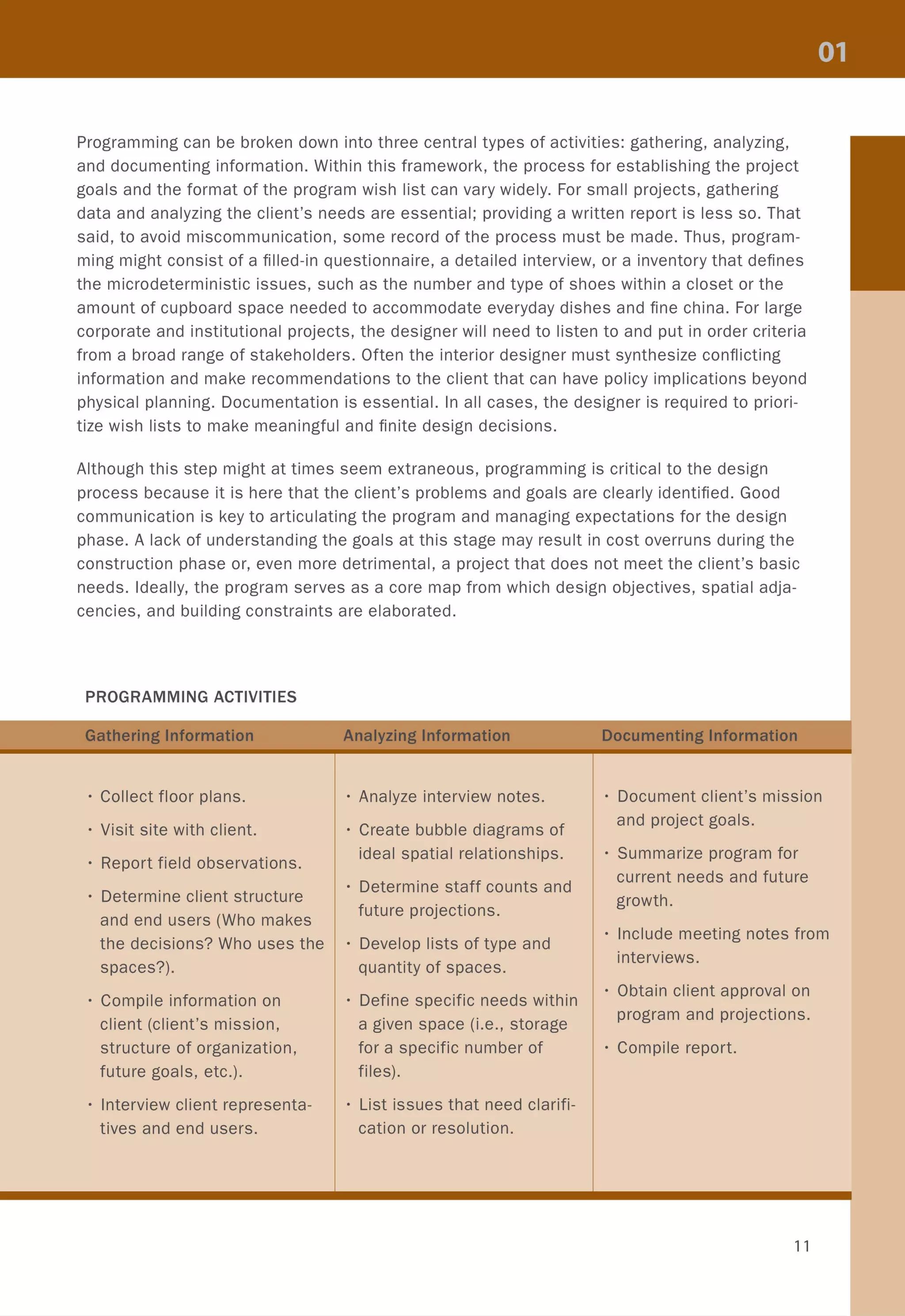
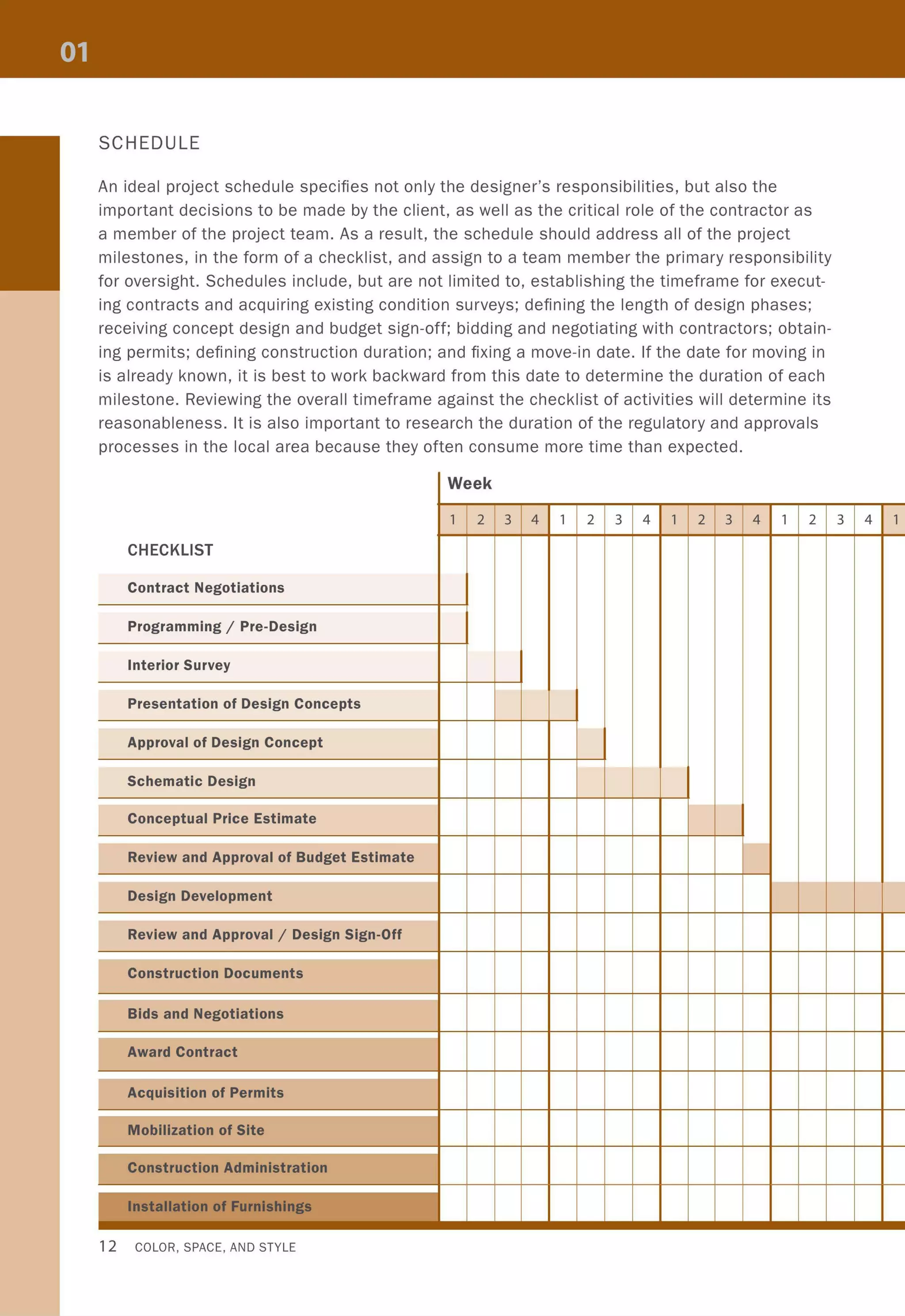
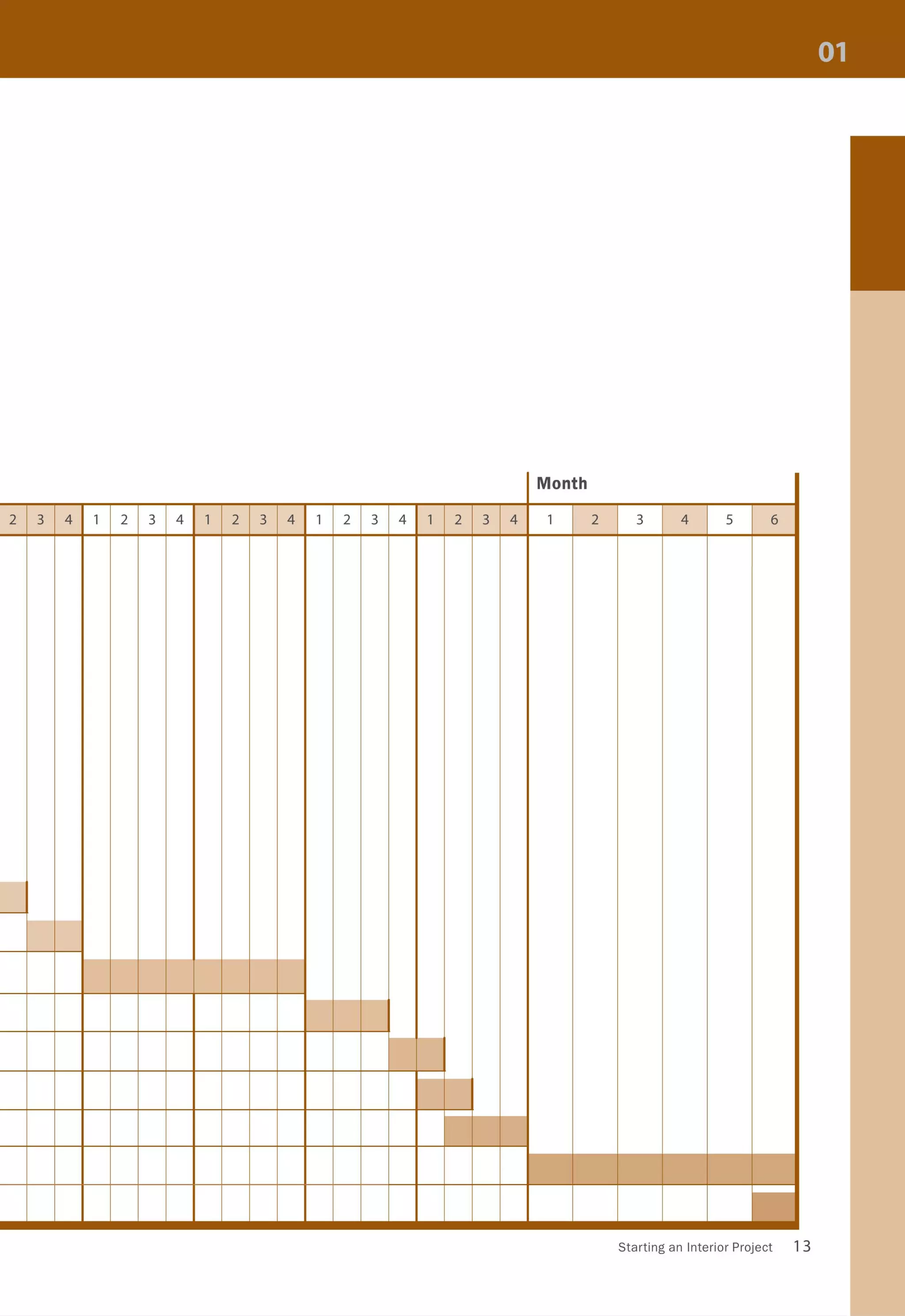
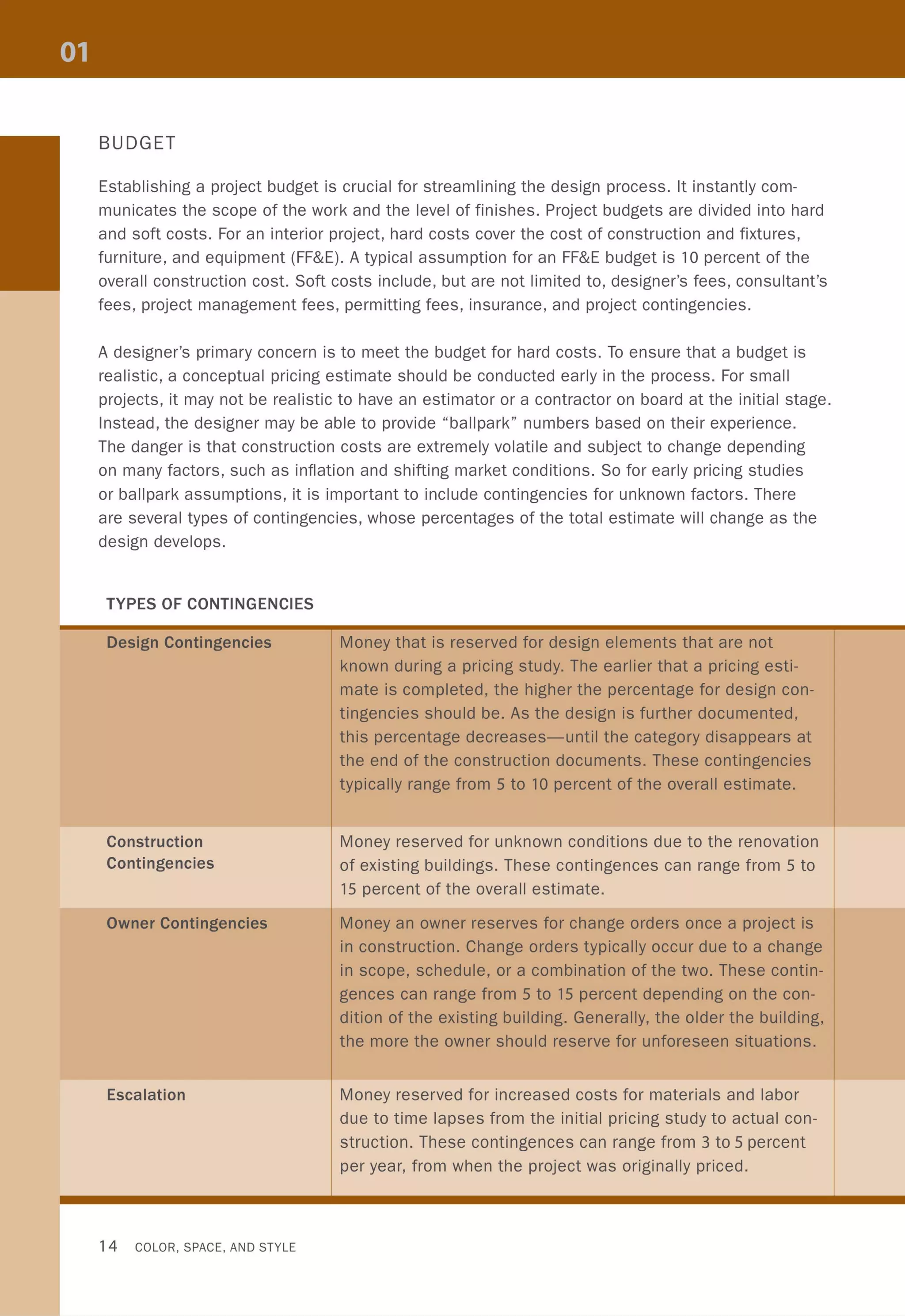
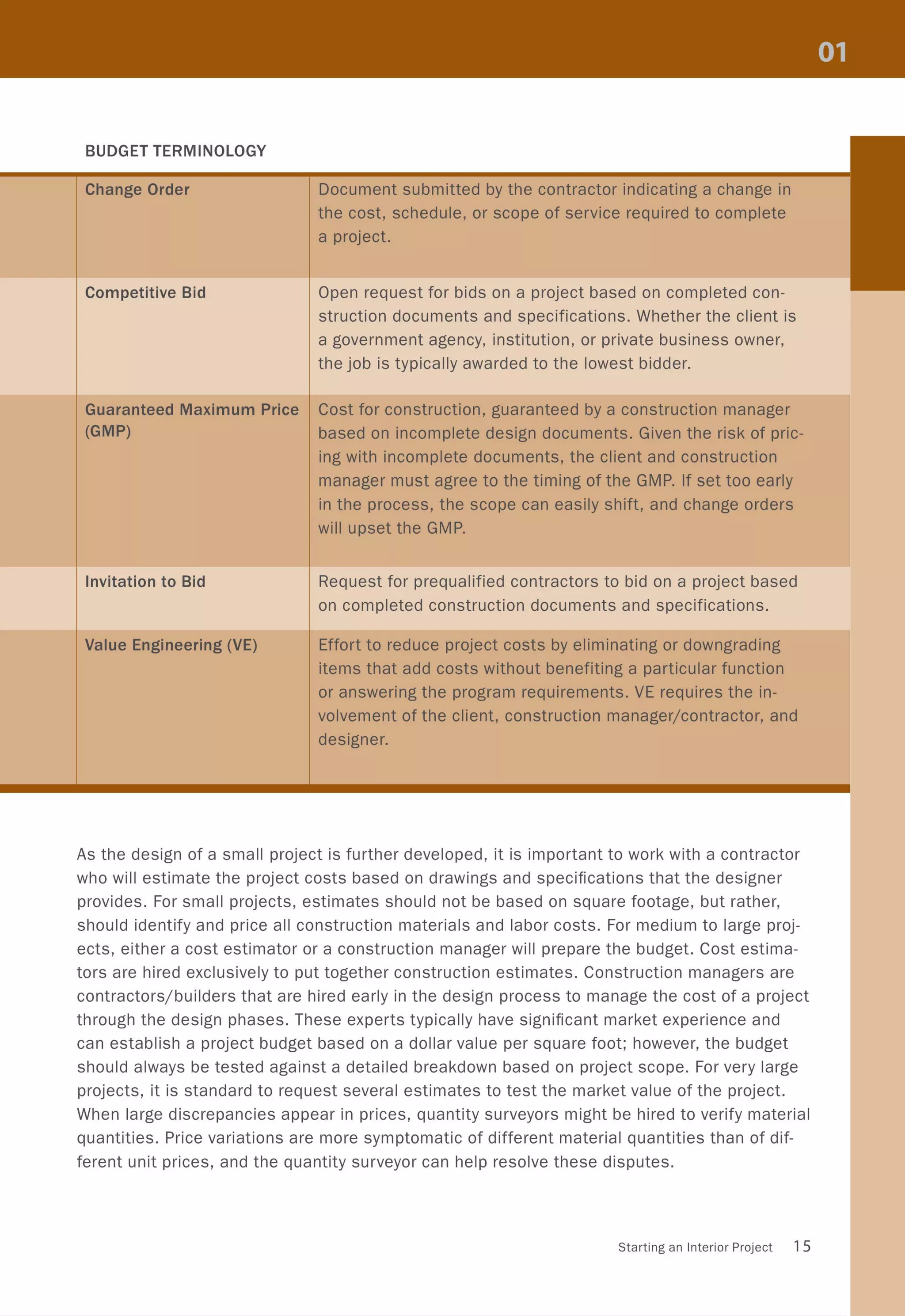
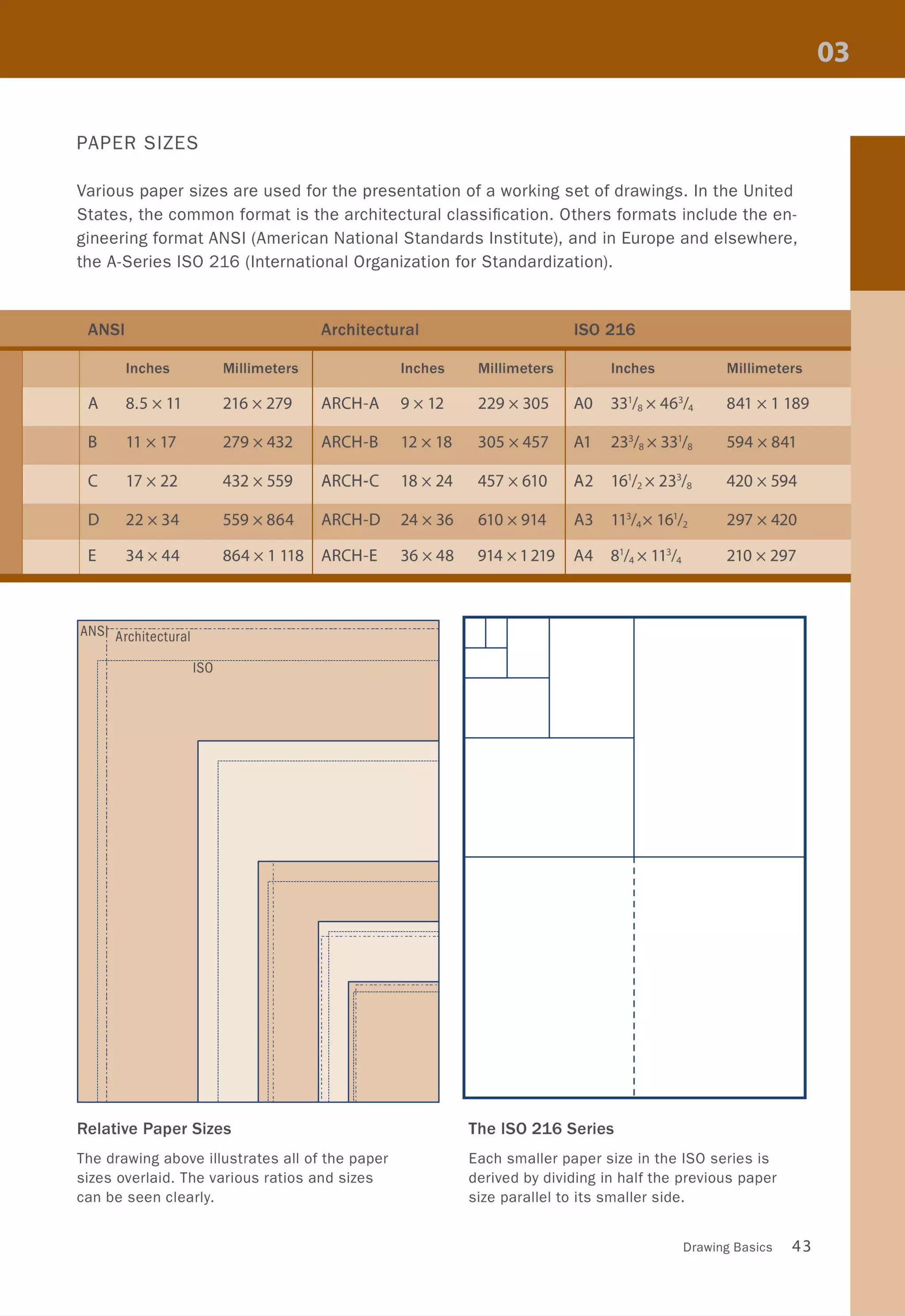
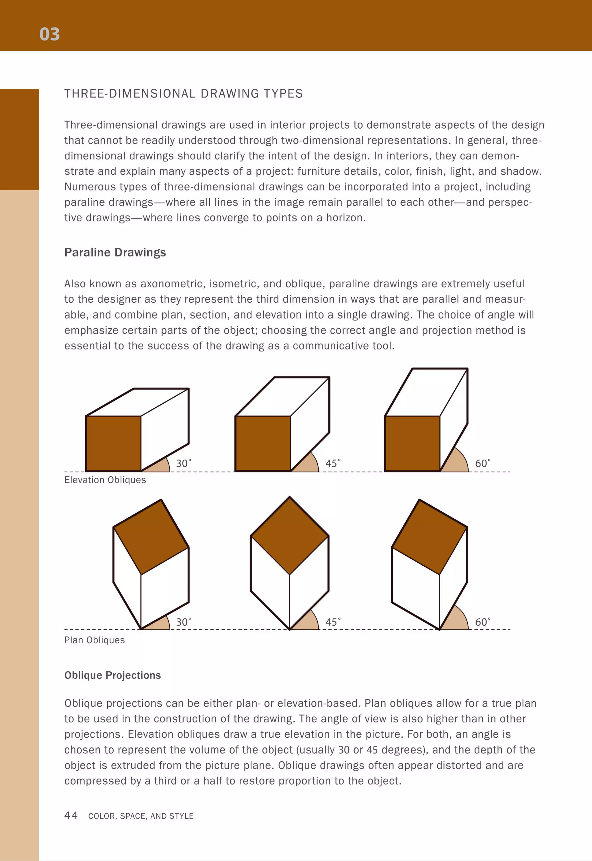
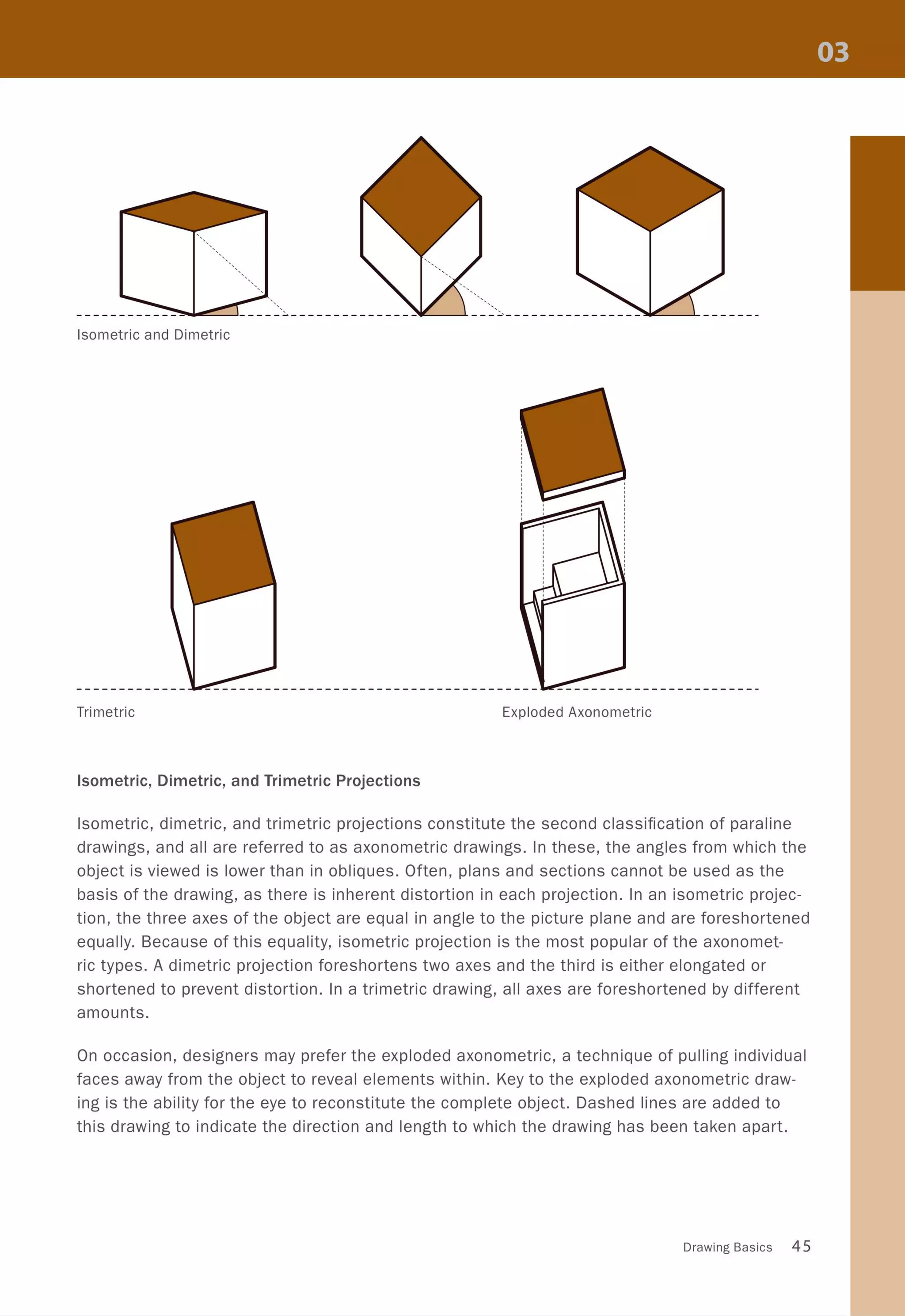
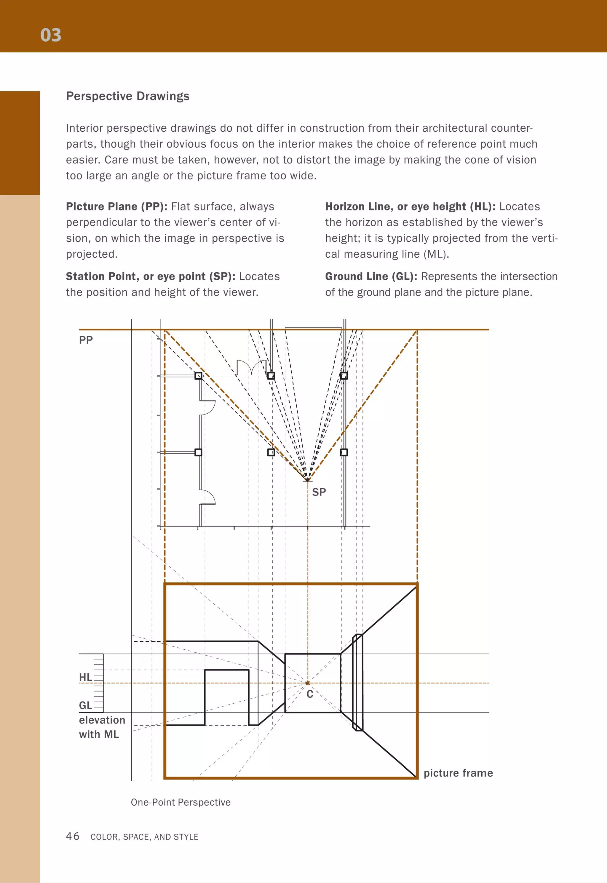
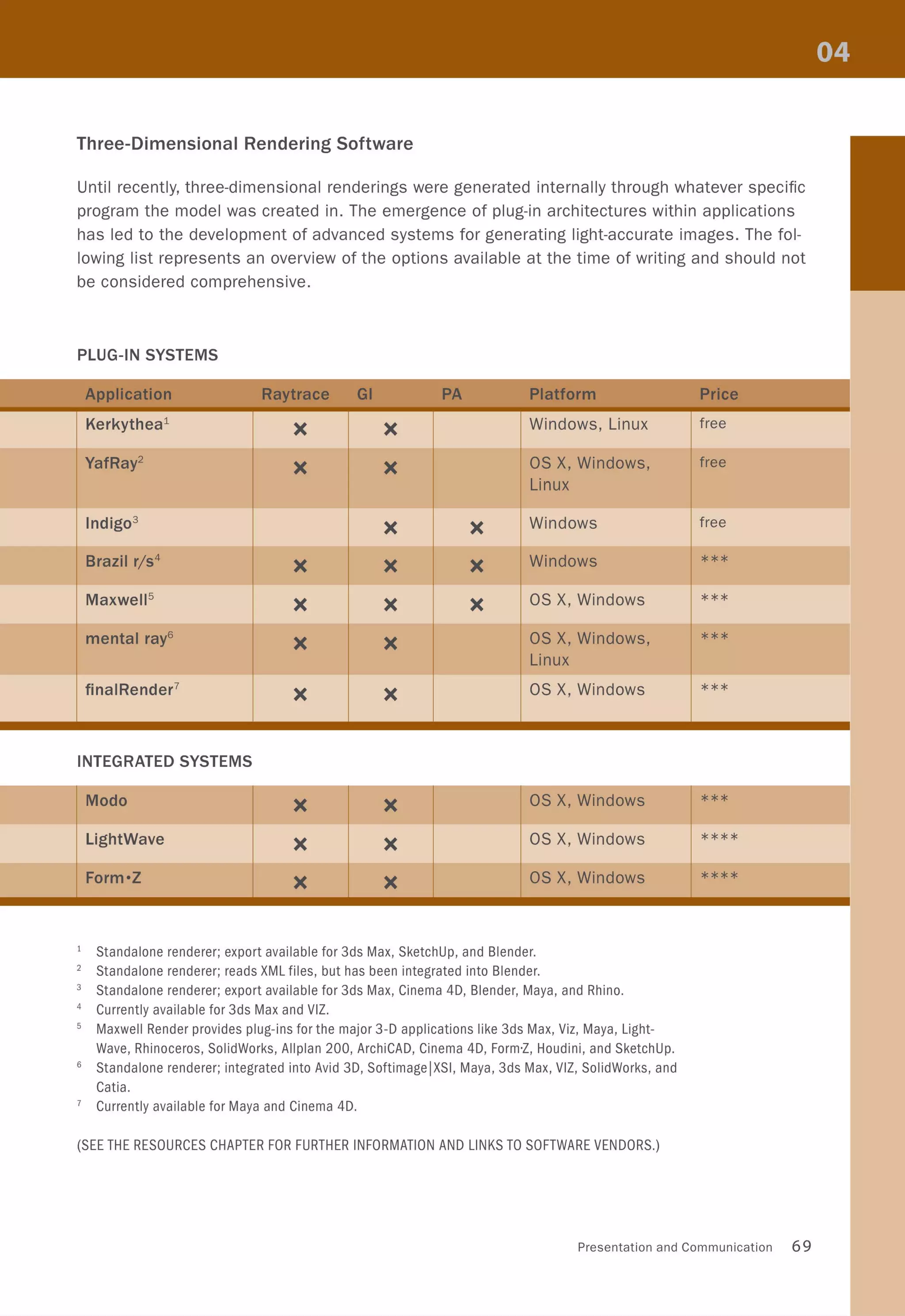
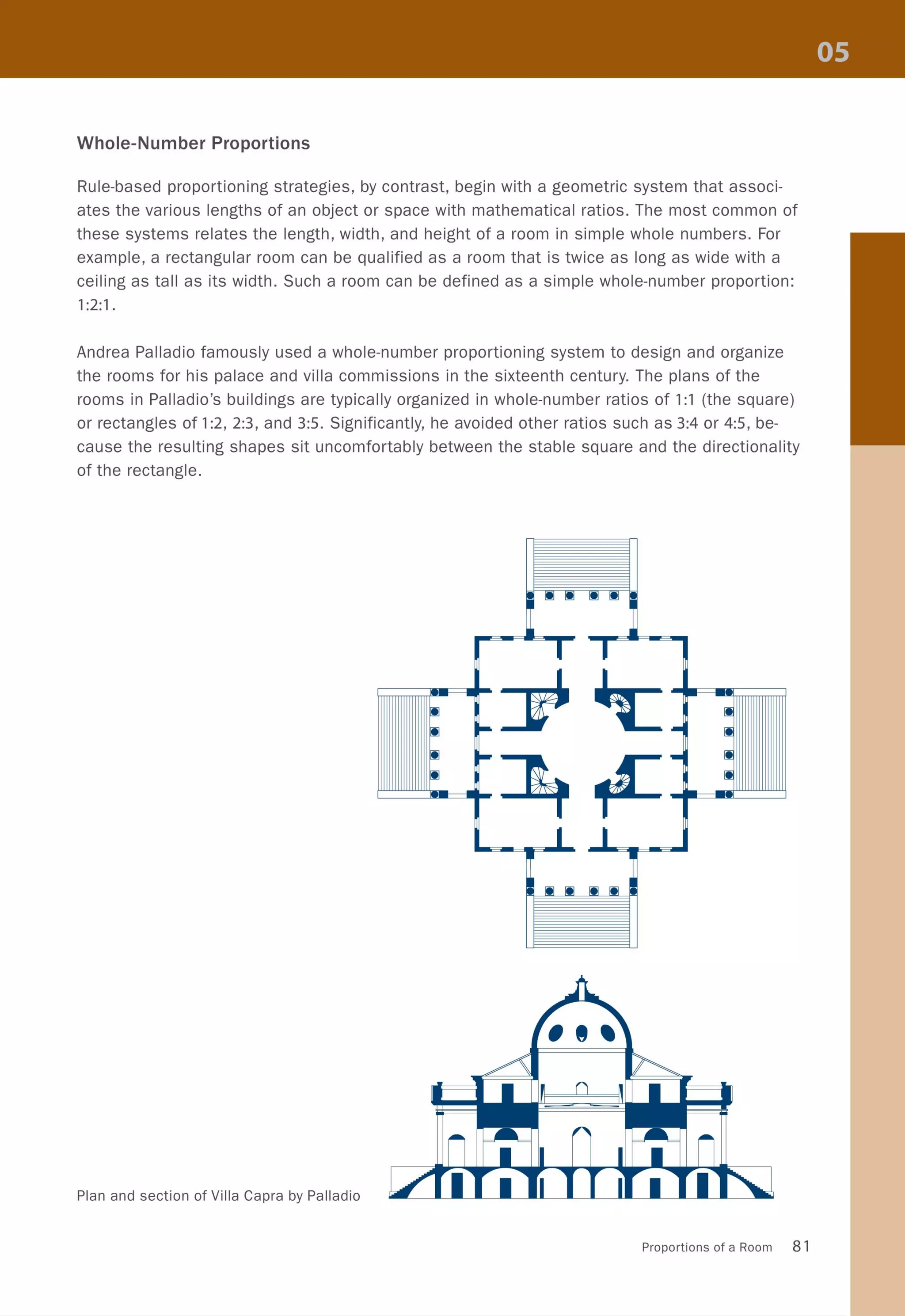
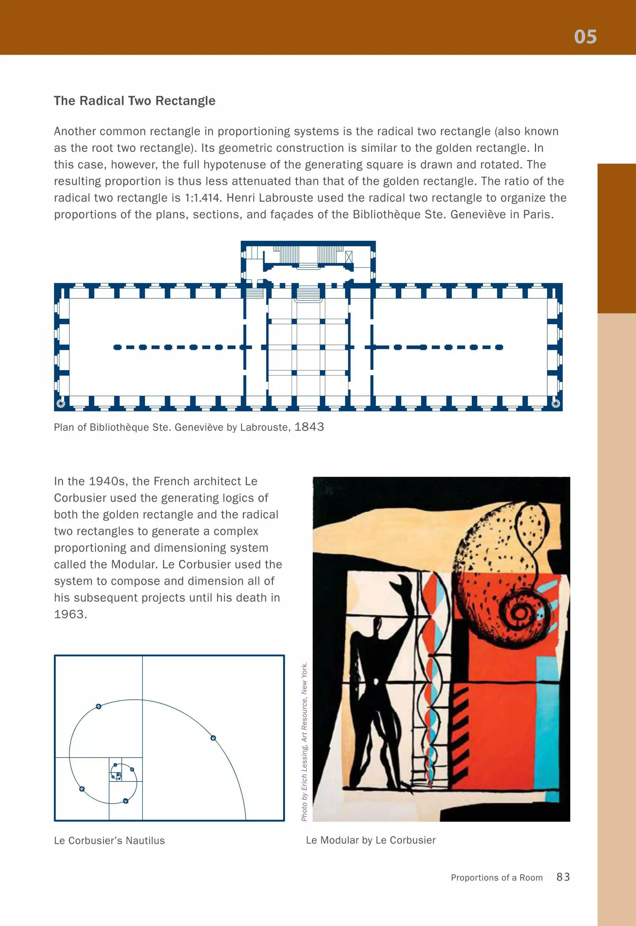
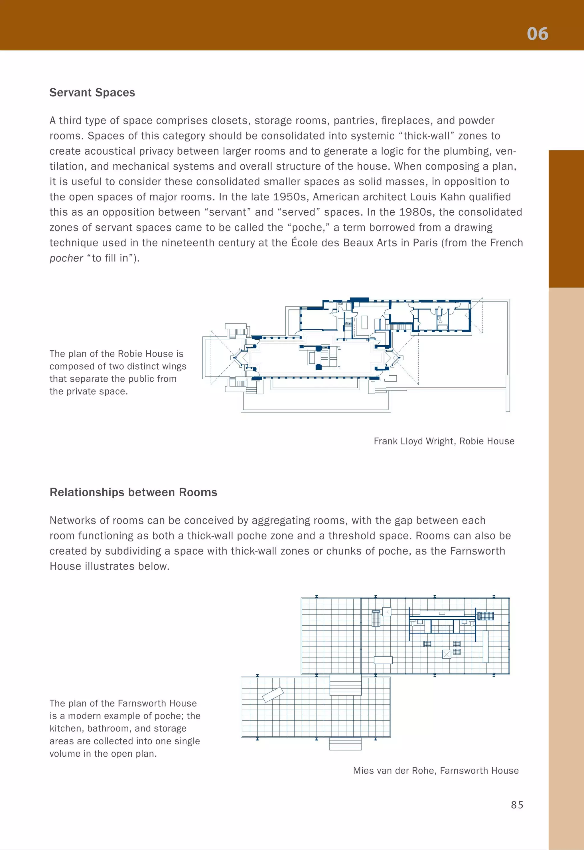
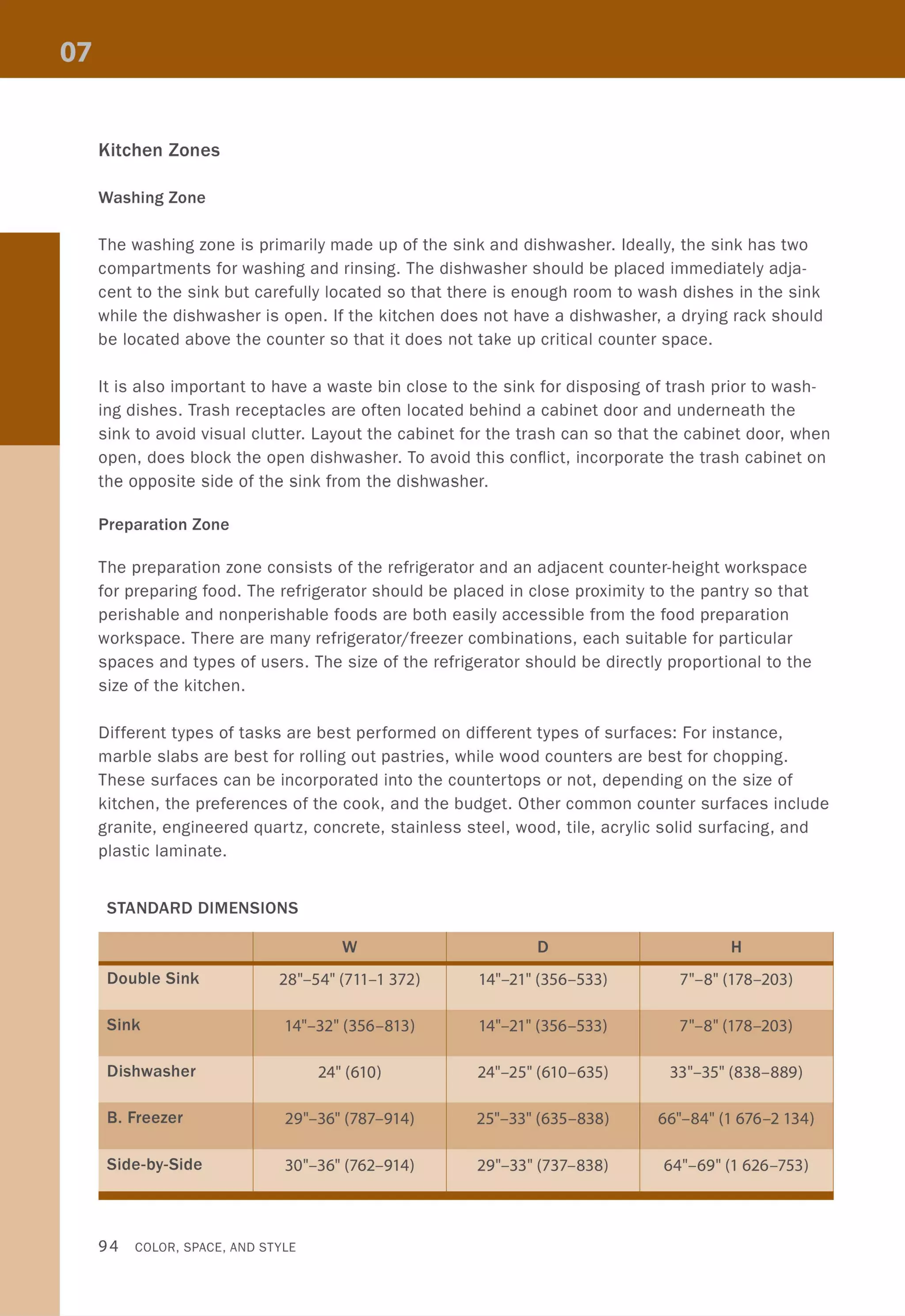
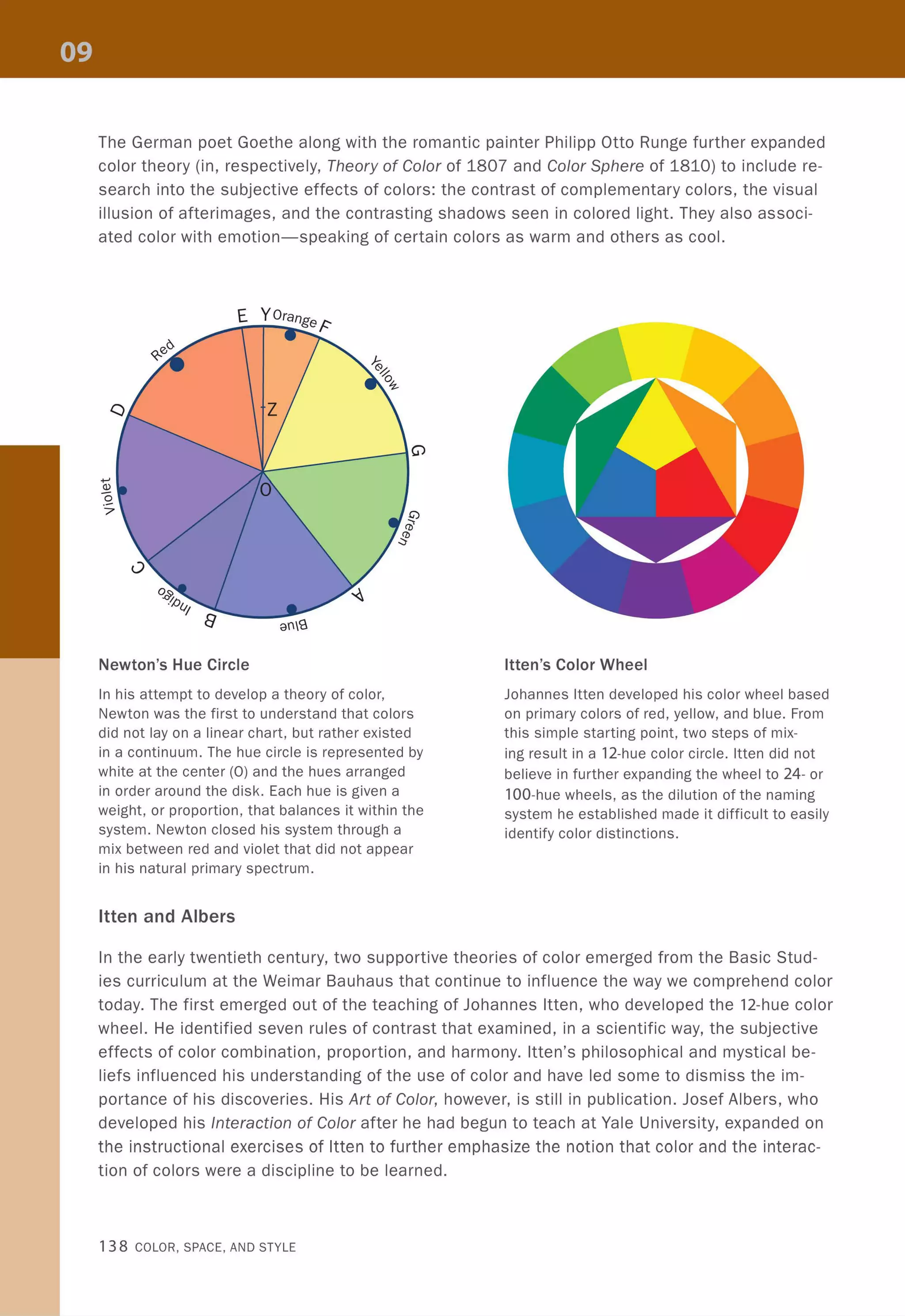
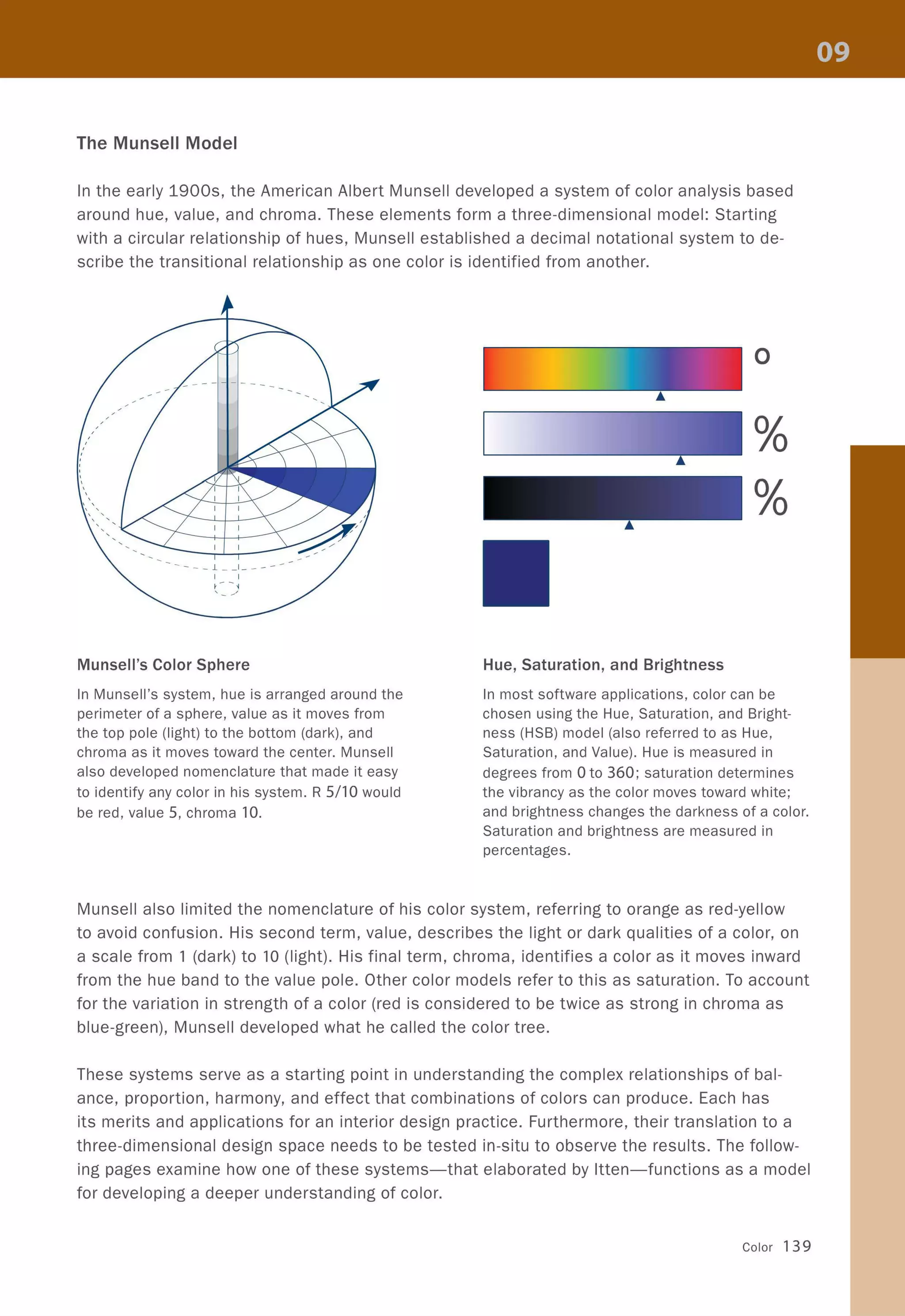
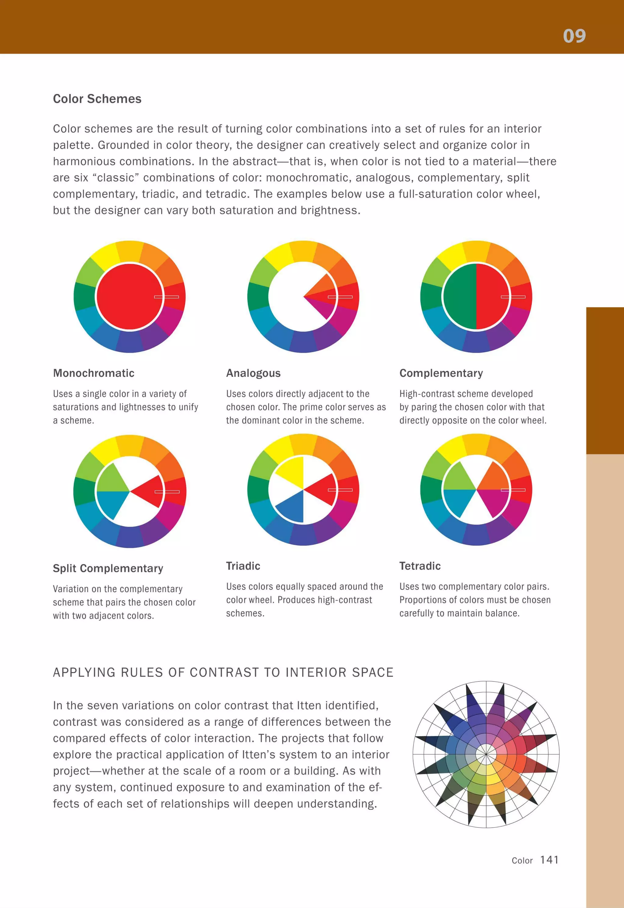
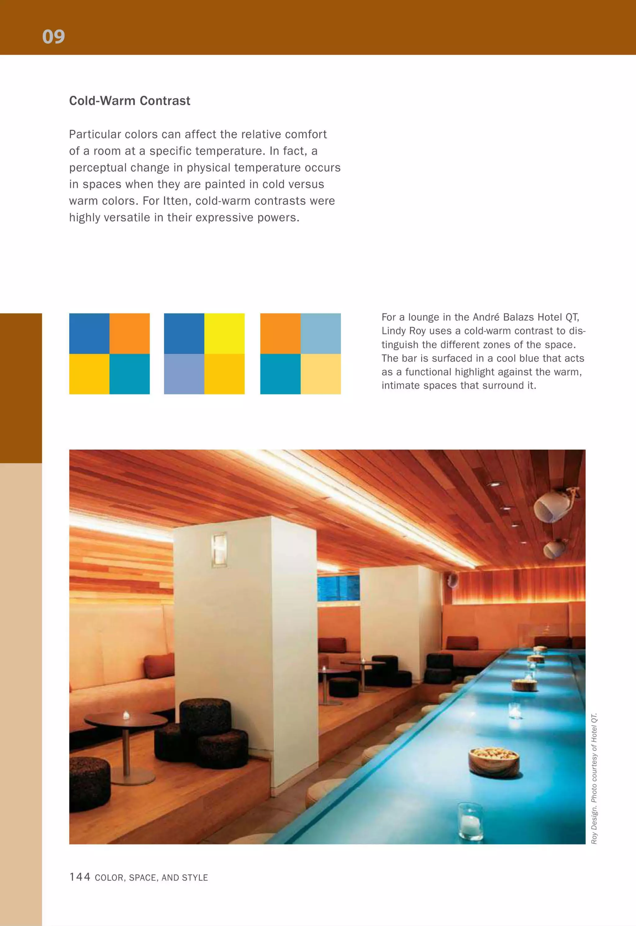
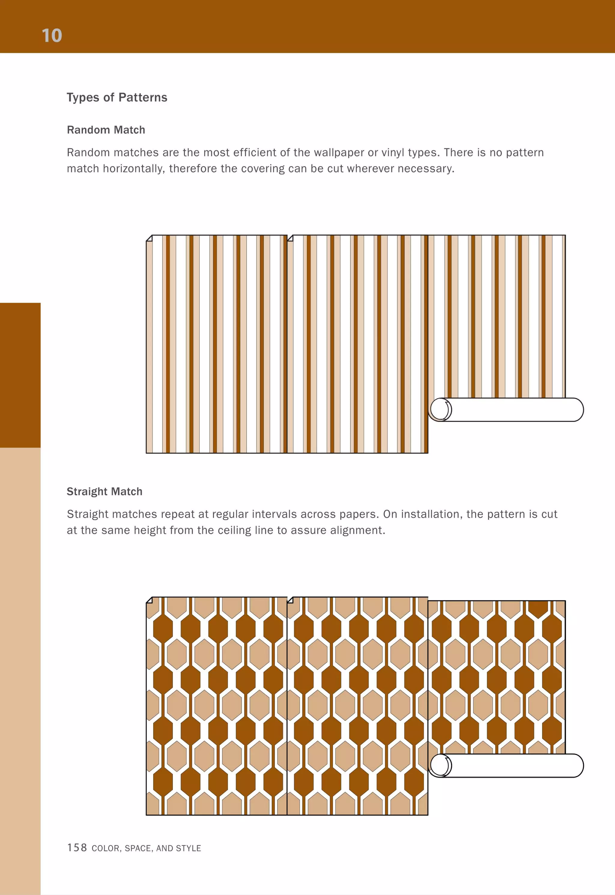
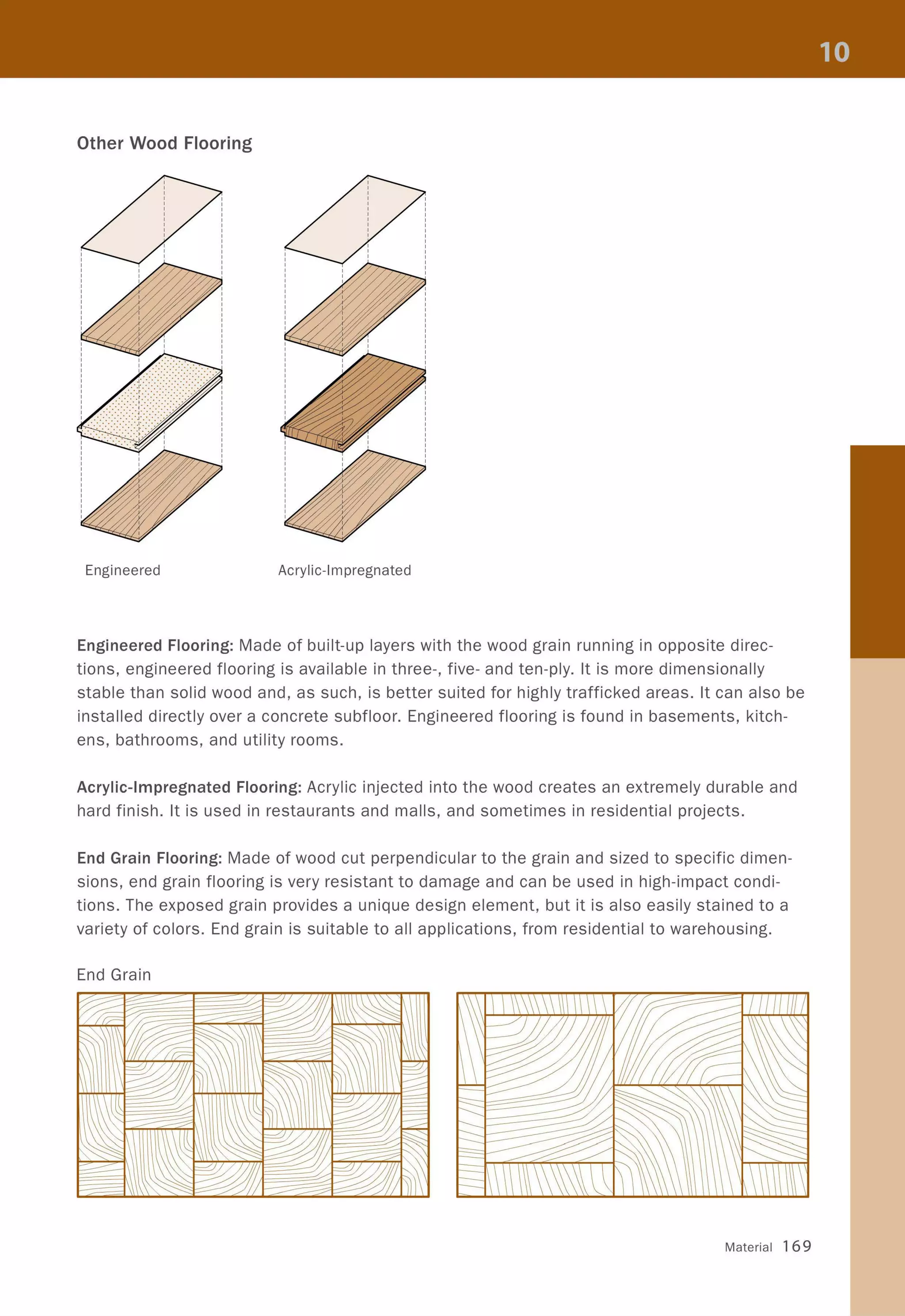
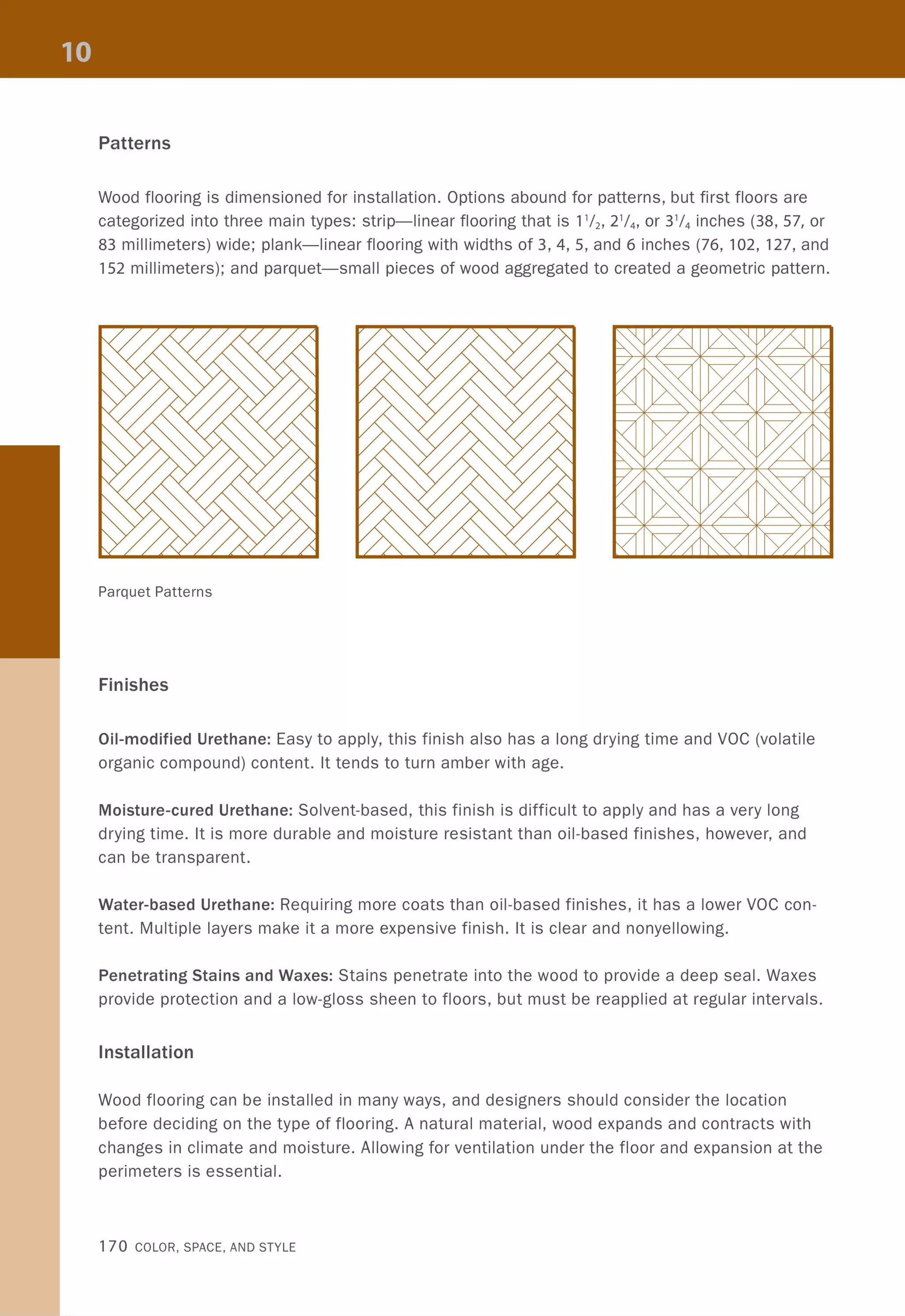
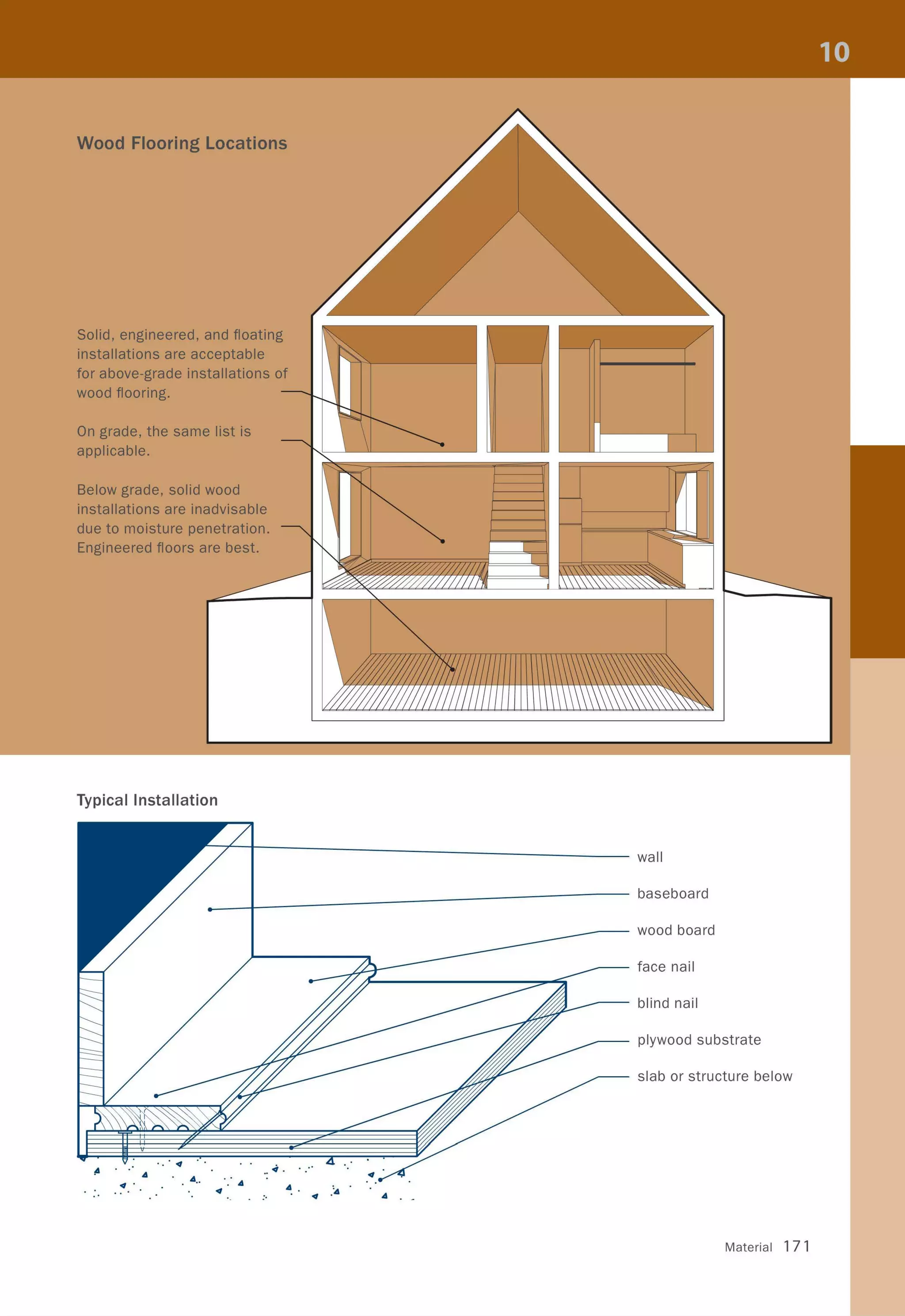
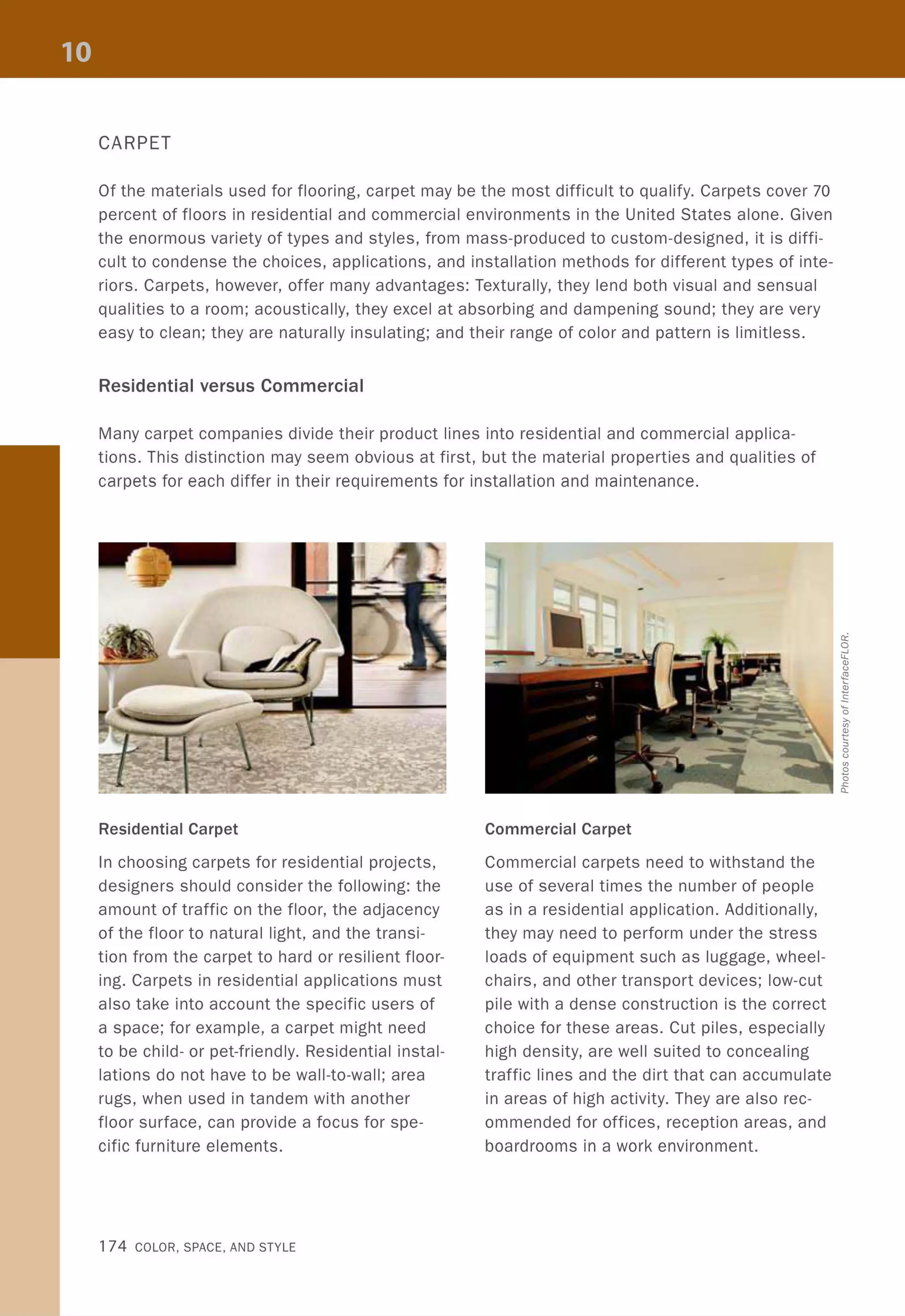
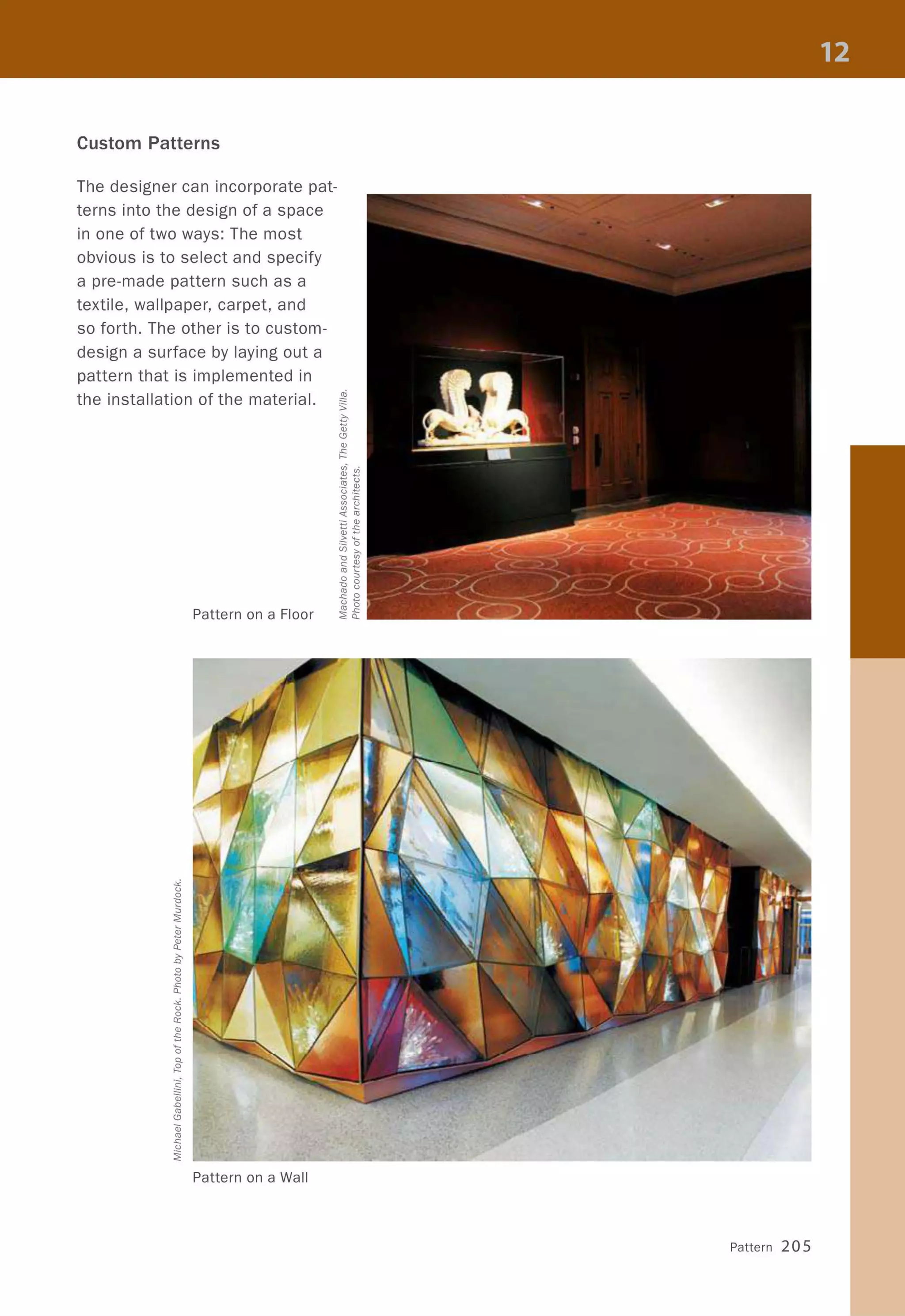
The document provides an overview of noithat101.com, a website for interior designers in Vietnam. It states that noithat101.com offers useful information for studying, researching, and working in interior design. The document encourages readers to provide feedback, support, and recommendations to help make noithat101.com the best forum for interior design in Vietnam. It thanks readers and wishes them success in exploring interior design through noithat101.com.


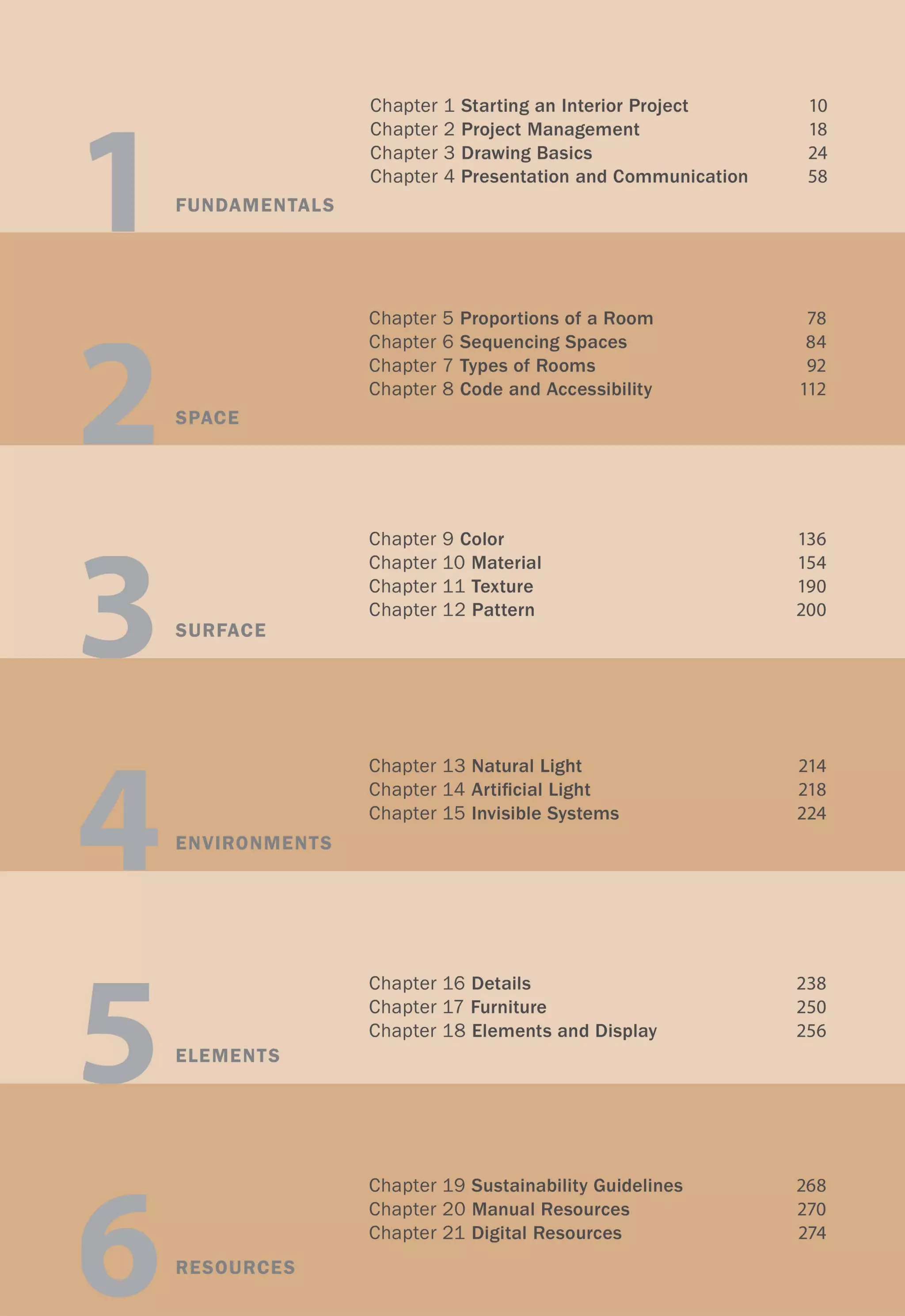


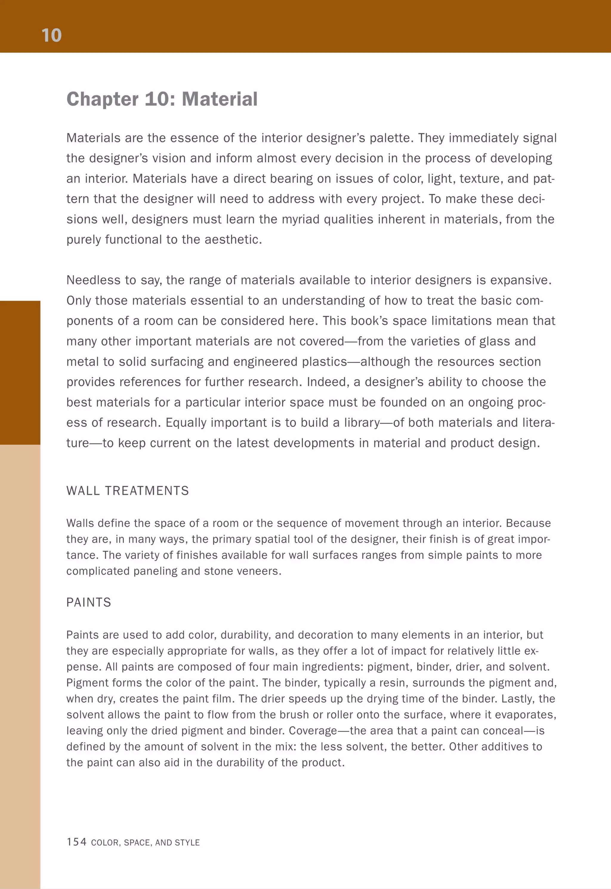
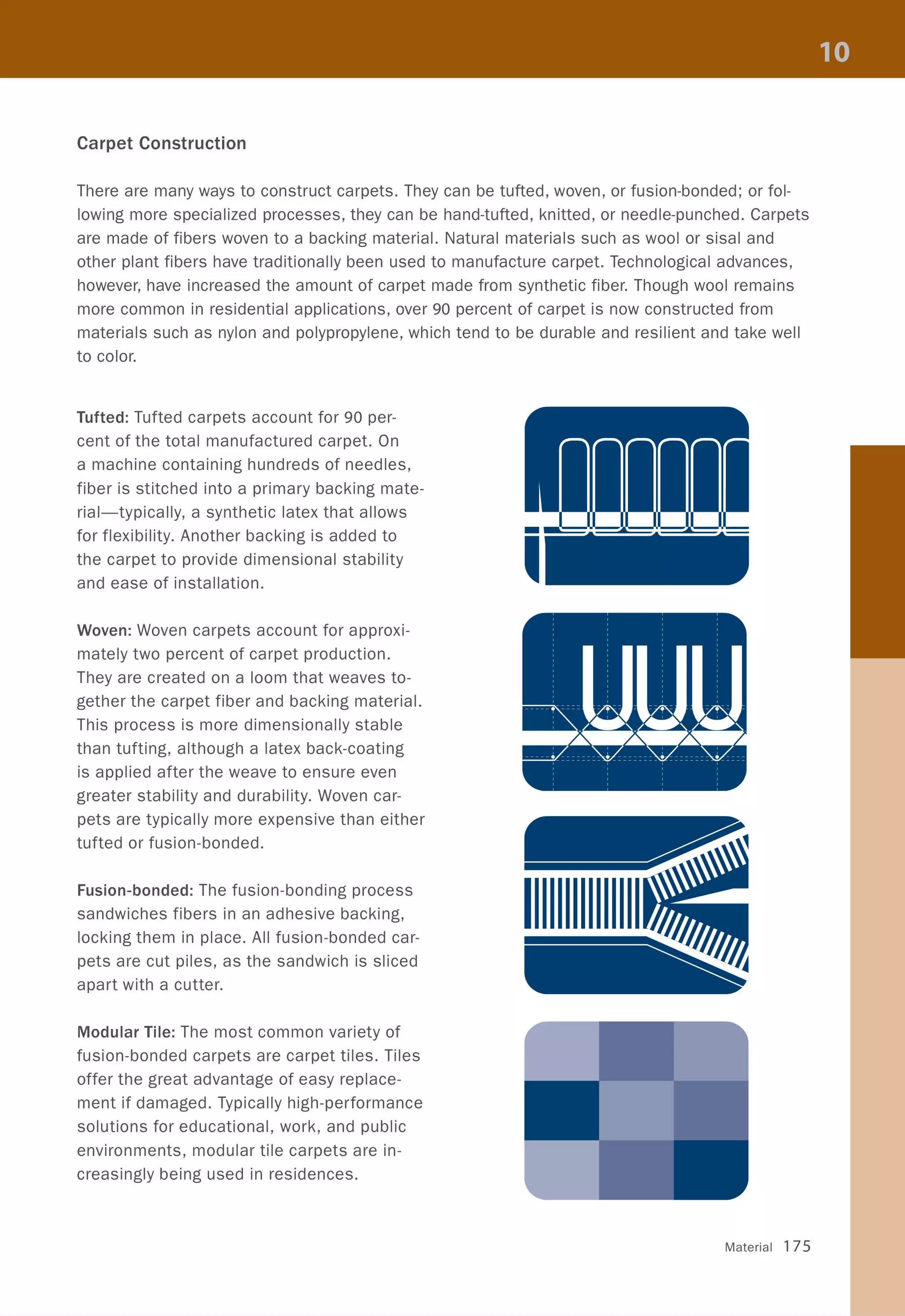
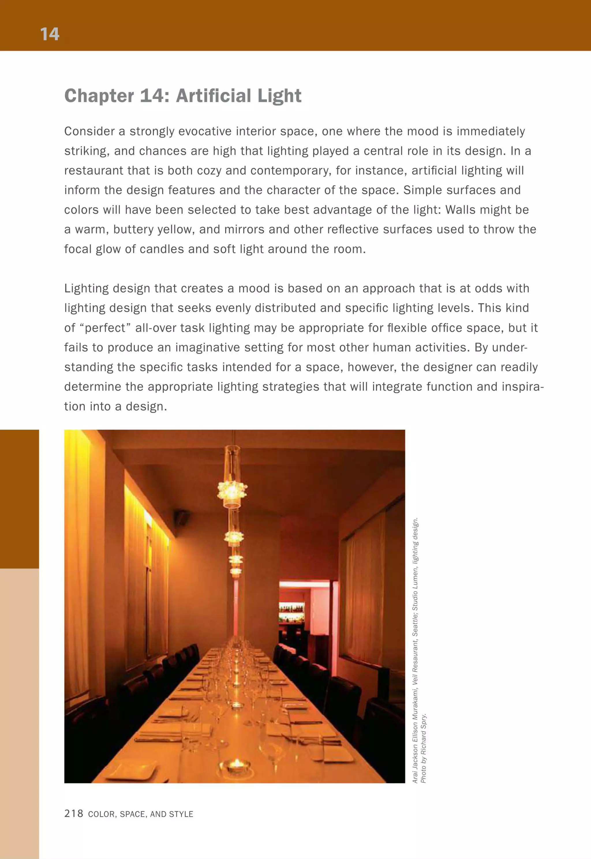
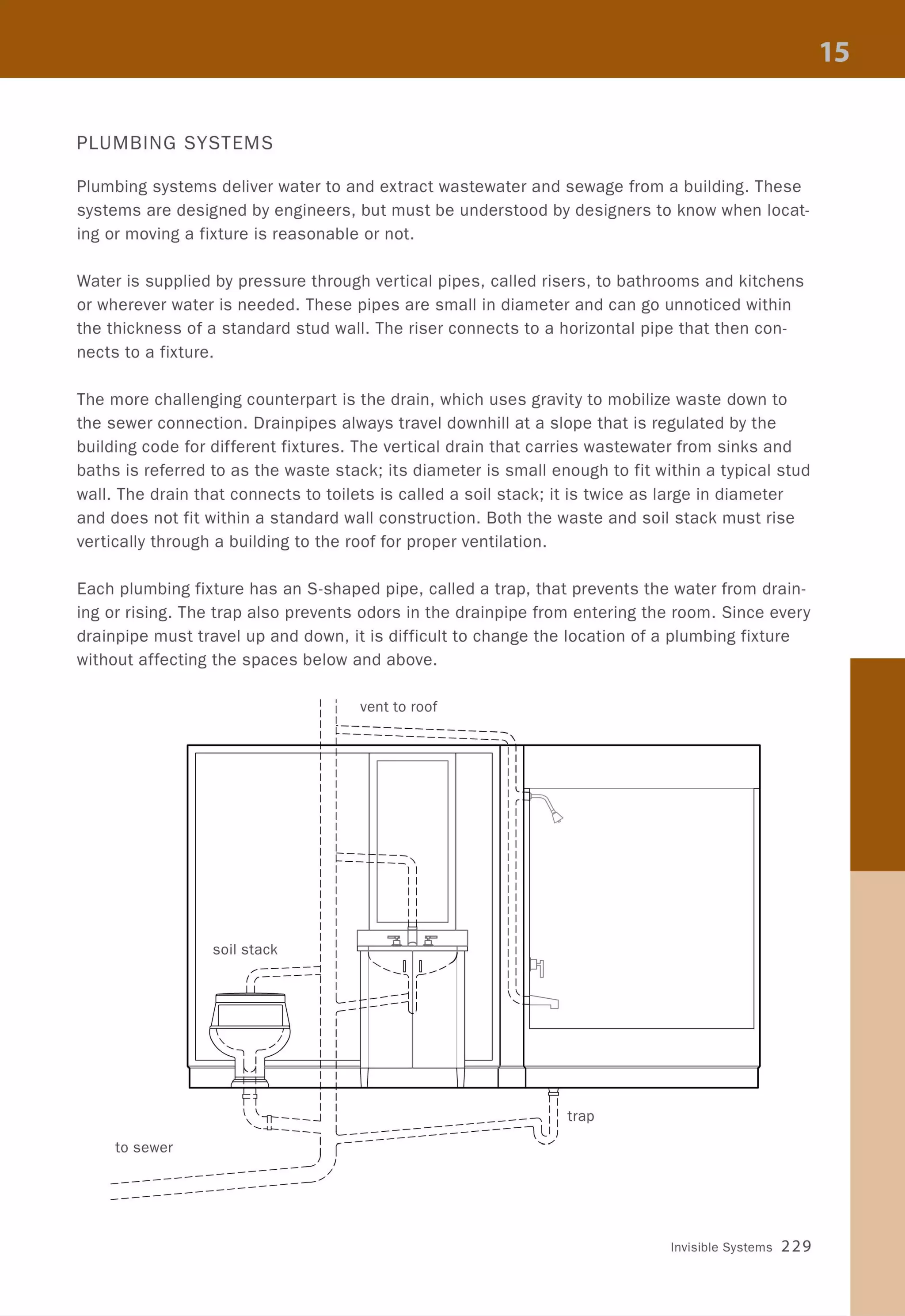
![Construction Calculators
Construction calculators provide easy access to a full range of conversions needed in the con-
struction-related industries. They can quickly convert feet and inches to their metric equiva-
lents, as well as translate units of weight and volume. Many models also calculate other data
that is useful to the interior designer, such as stair length and riser height, stringer length,
stud spacing, and material calculations, such as paint or wallpaper quantities.
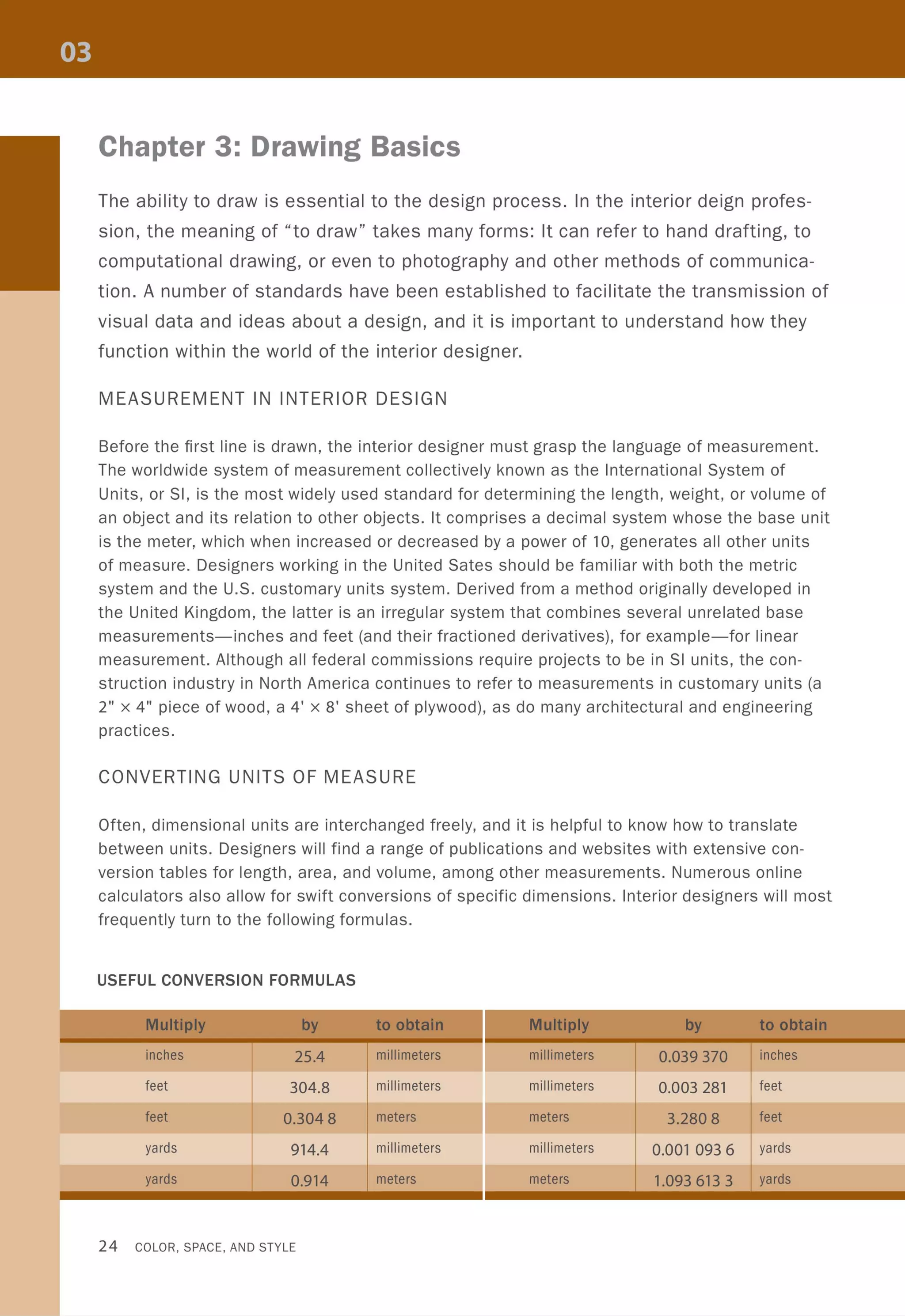
Every attempt has been made
in this book to represent accu-
rately the relationship between
customary and SI units. Except
where noted, soft conversions
are used throughout-rounding
up 12 inches to 305 millime-
ters rather than 304.8-and,
due to constraints of space,
are usually written as follows:
36" (914).
1,,· "..I ·' -.,~ ~
FEET INCH
~~) [~) [~) [~) [~)
~d F~) [Stair]) [eirc]) [R/wal~ [ JaCk])
GB8E3[o
[8[8808
~ m[[][2JG
8GJw[§J0
EHl]wwG
0@]Q~[±]
Drawing Basics 27](https://image.slidesharecdn.com/colorspaceandstyle-allthedetails-noithat101-170426124809/75/Color-Space-and-Style-29-2048.jpg)

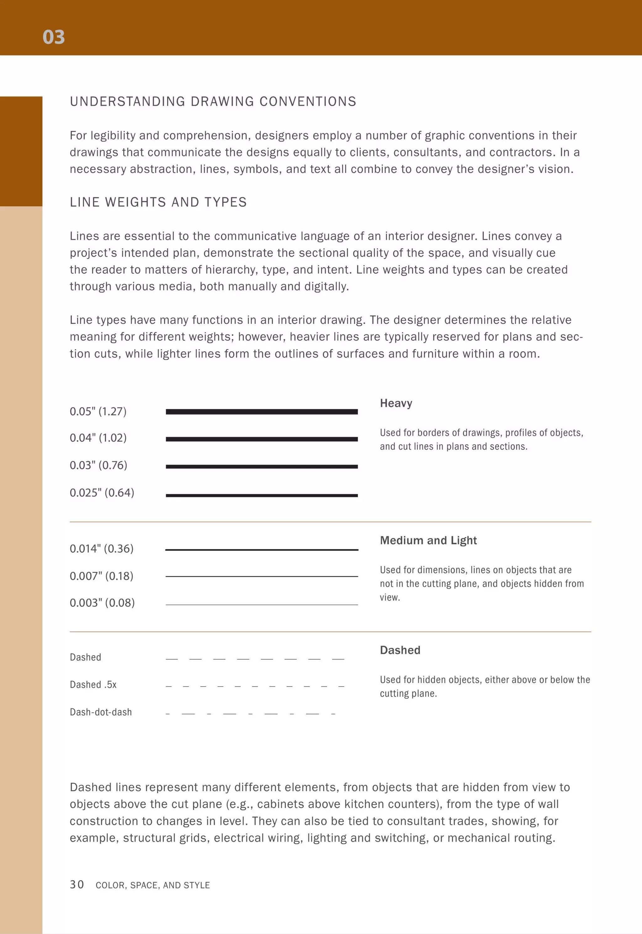


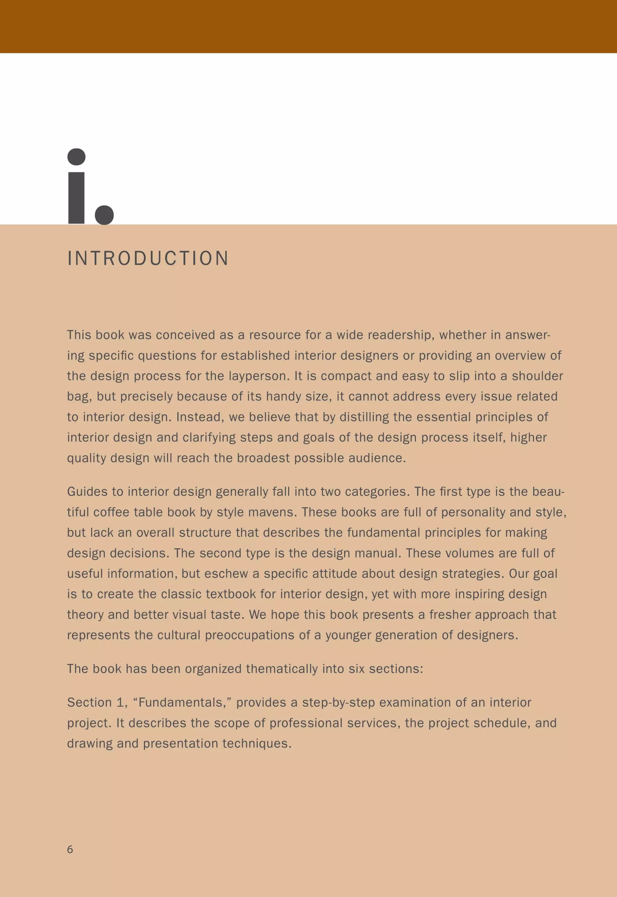
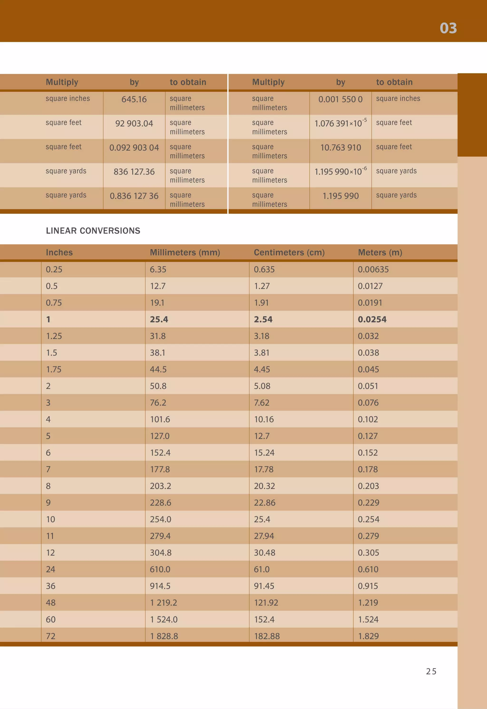
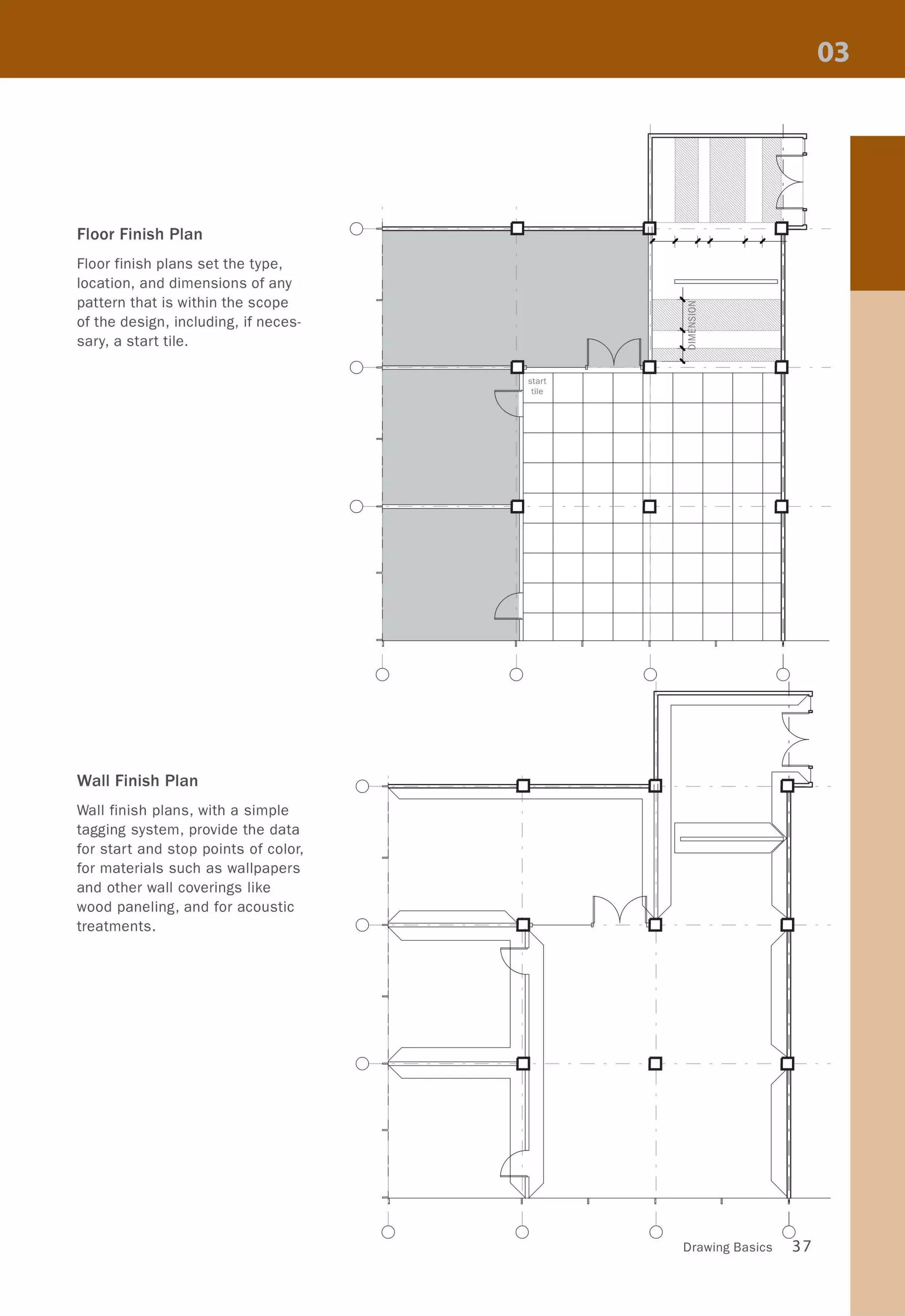
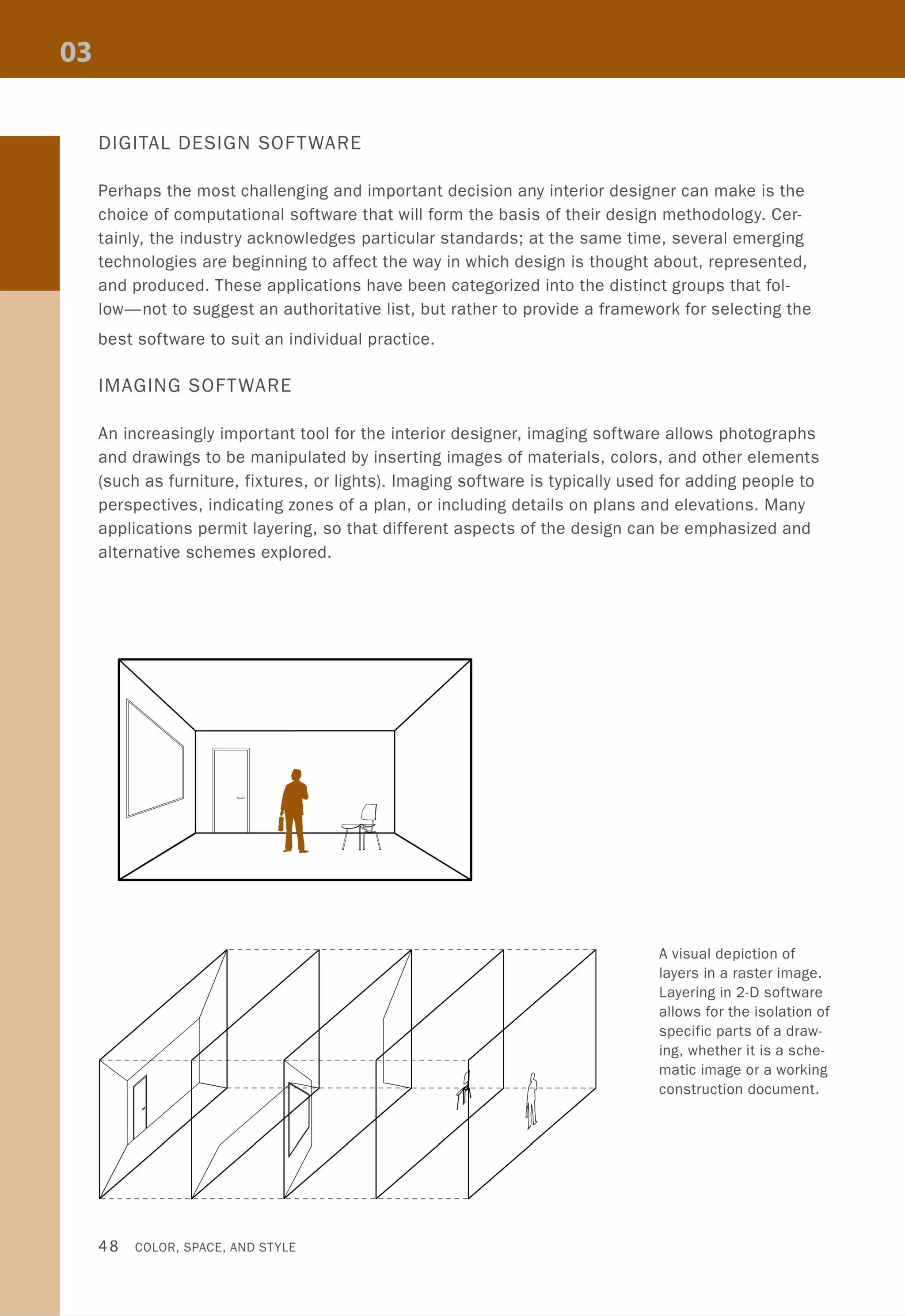
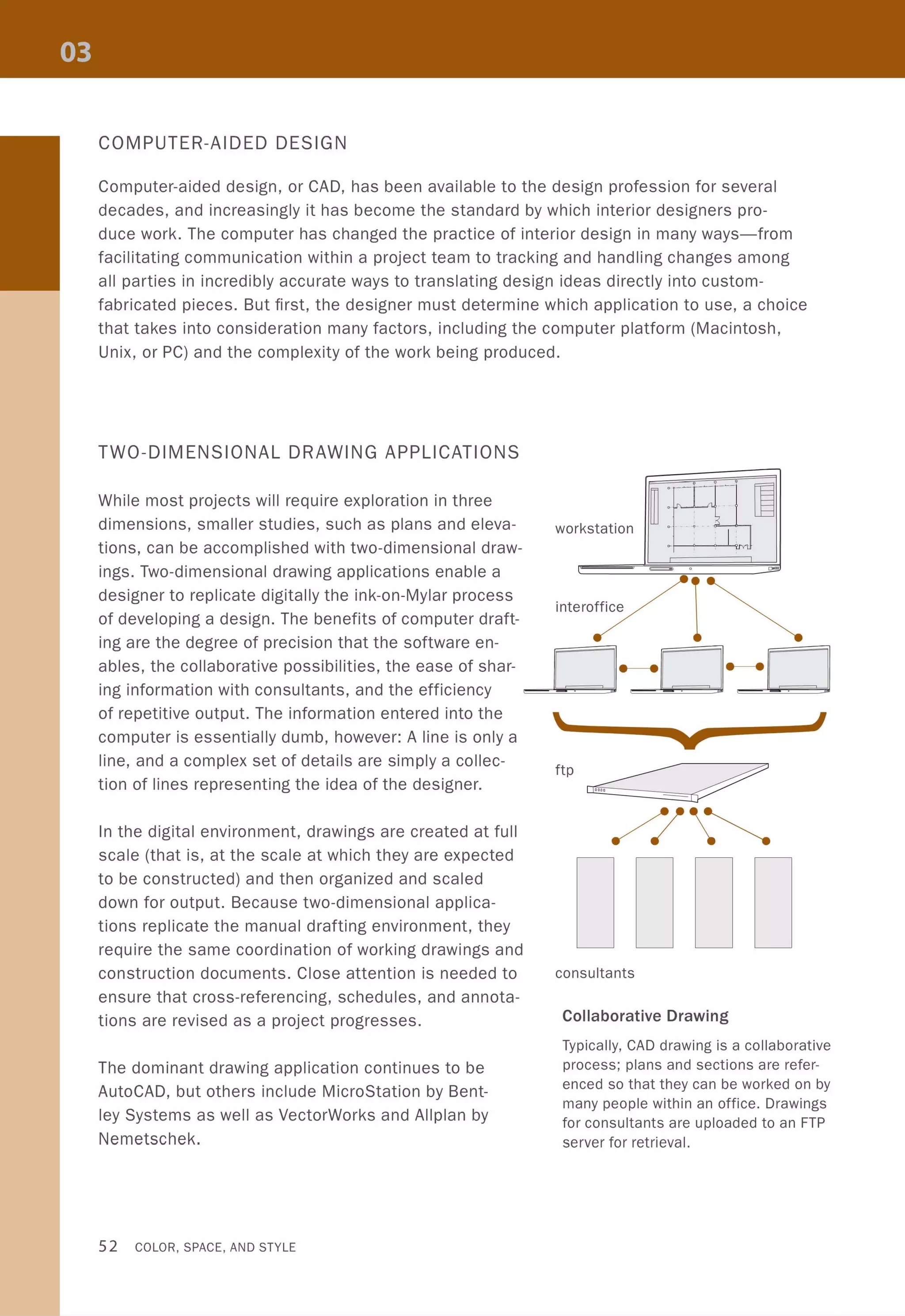
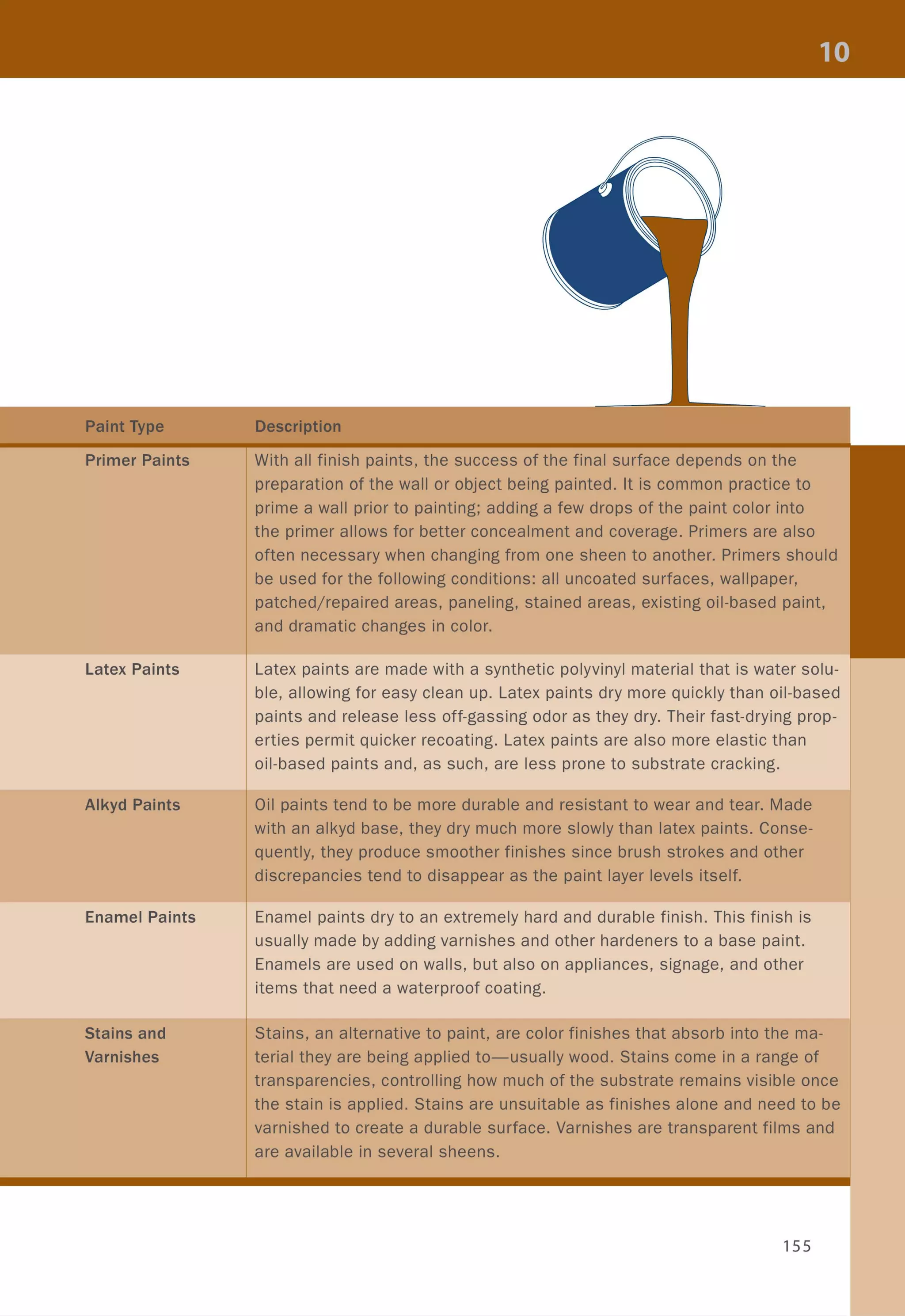
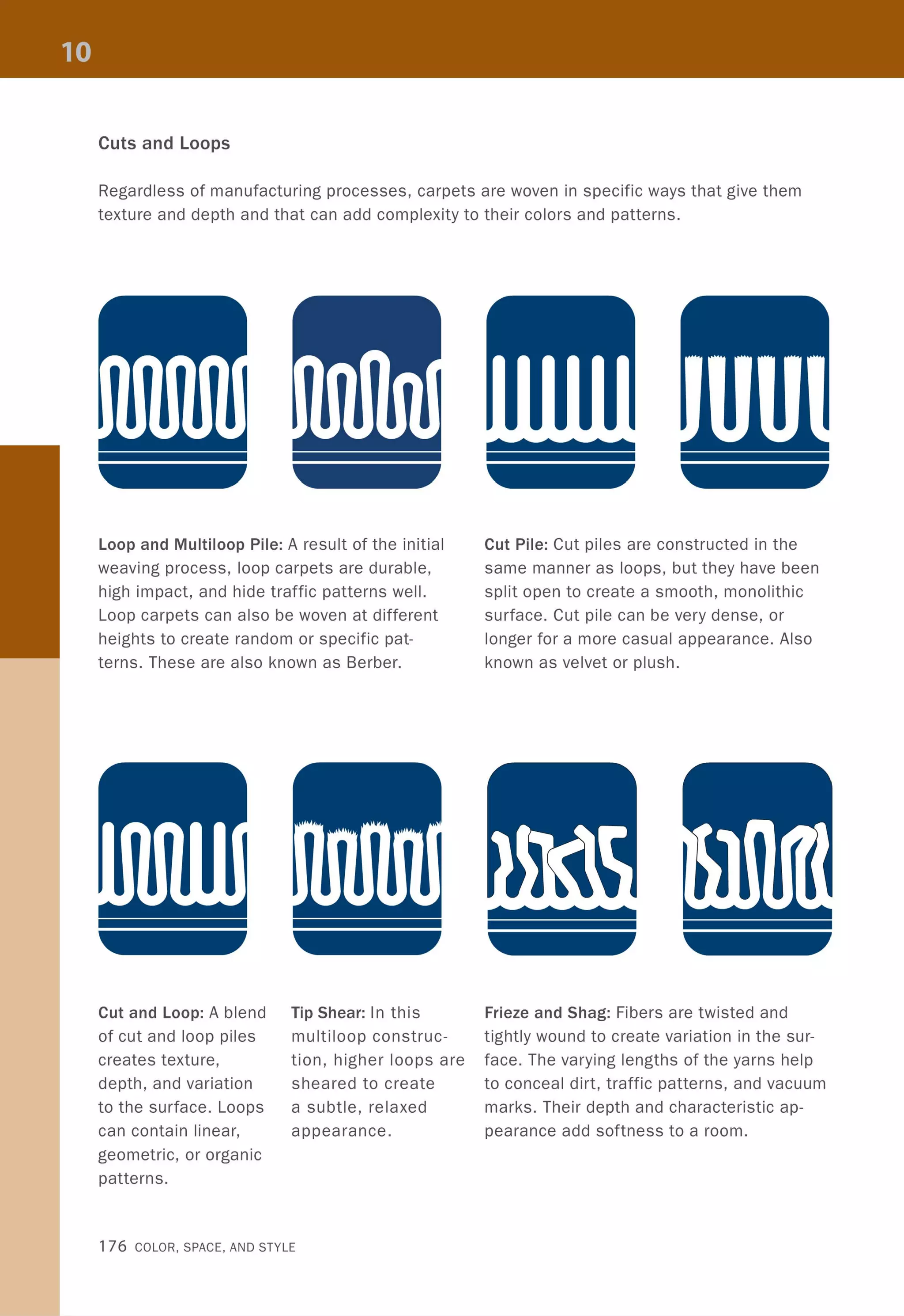
![Symbols on a plan drawing are keyed to other drawings in the set, including reflected ceiling
plans, elevations, sections, and details. Elements needed to implement a design are thus
easily read from drawing to drawing, and revisions are readily coordinated. Dimensions are
indicated in strings around the plan, or in some cases, within the plan itself. Legibility of text
and numbers is crucial to reading a plan.
@
-~==~~====~~~~~
CD- -- -- -- -- ~ - -- -- -- -- -- -- -- -_~I;;;;;;;;;;;;;;;;;;;;;;;;~Iu,.I~ ______ _L----I----#-_
,
I
I
,
,
I /
~
'I l
Y,
I
1 .;
zpo - - - --- I
,
00I
,
I,,,, ,,,
I,,,,
I,
[0
A
,
I I
~,
4 SHE~T. 2I ~,
I 31,
I I
, ,,
(
- f-- -t 1-- 1',
!NuM
, I
I
, ,,
I :
,
- - ---~
~ I ,
I
z
0
I
J ) U5
-- - - z, w
I
::<
'",
I- -- --------- ,
I,,
1
, INUMBER ]
I I NAM): I
, I
I,
I
I I
,
II I
I I,
,
-----
I------
,
I,
I I
1
I
I I, ------ I
I I ,
I
G)- -------- ------ r ----- r ---~--------------- r ------ _~
I' I I
oDRAWING NAME
SCALE
L LL
I I l
Drawing Basics 33](https://image.slidesharecdn.com/colorspaceandstyle-allthedetails-noithat101-170426124809/75/Color-Space-and-Style-35-2048.jpg)
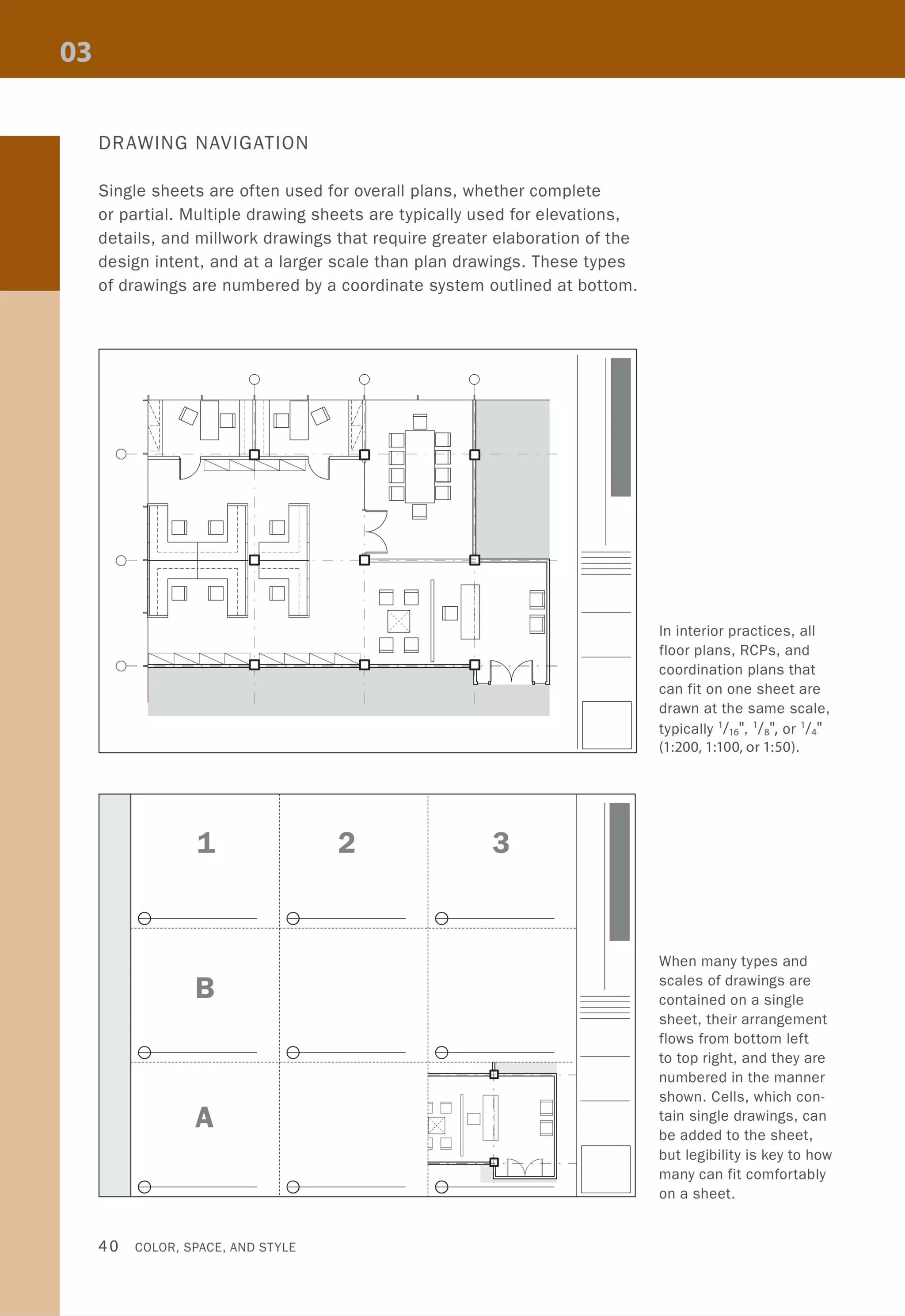
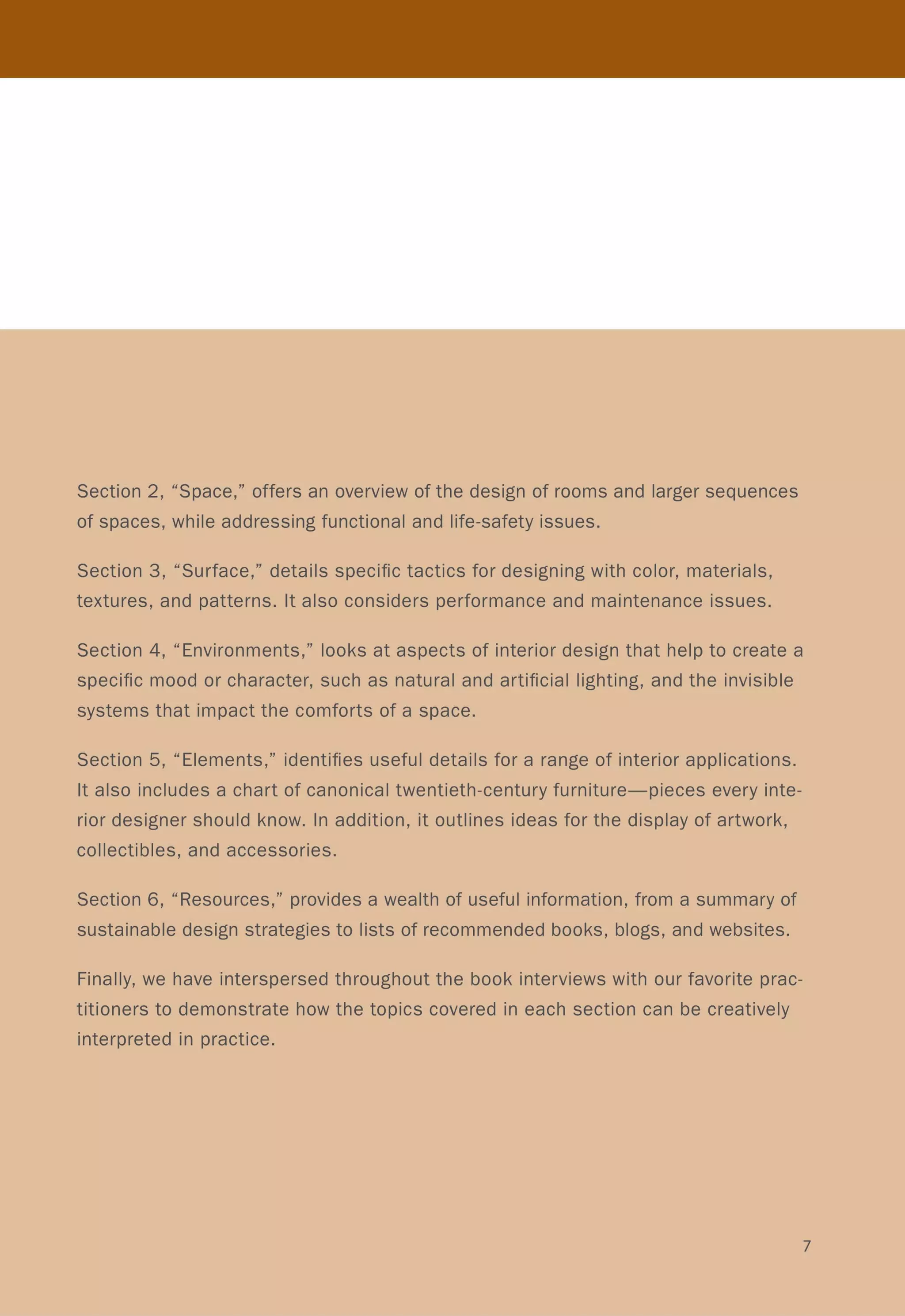
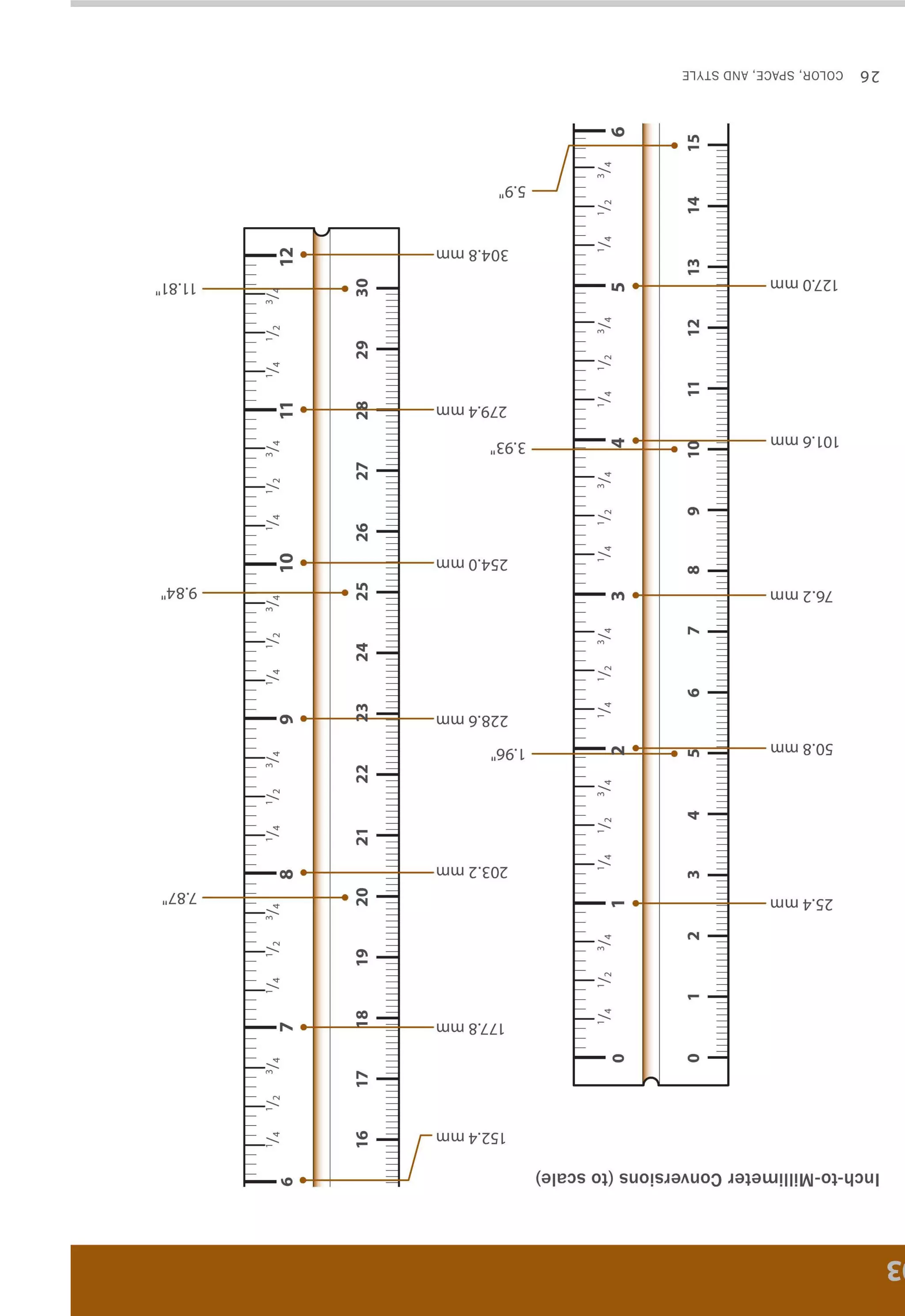
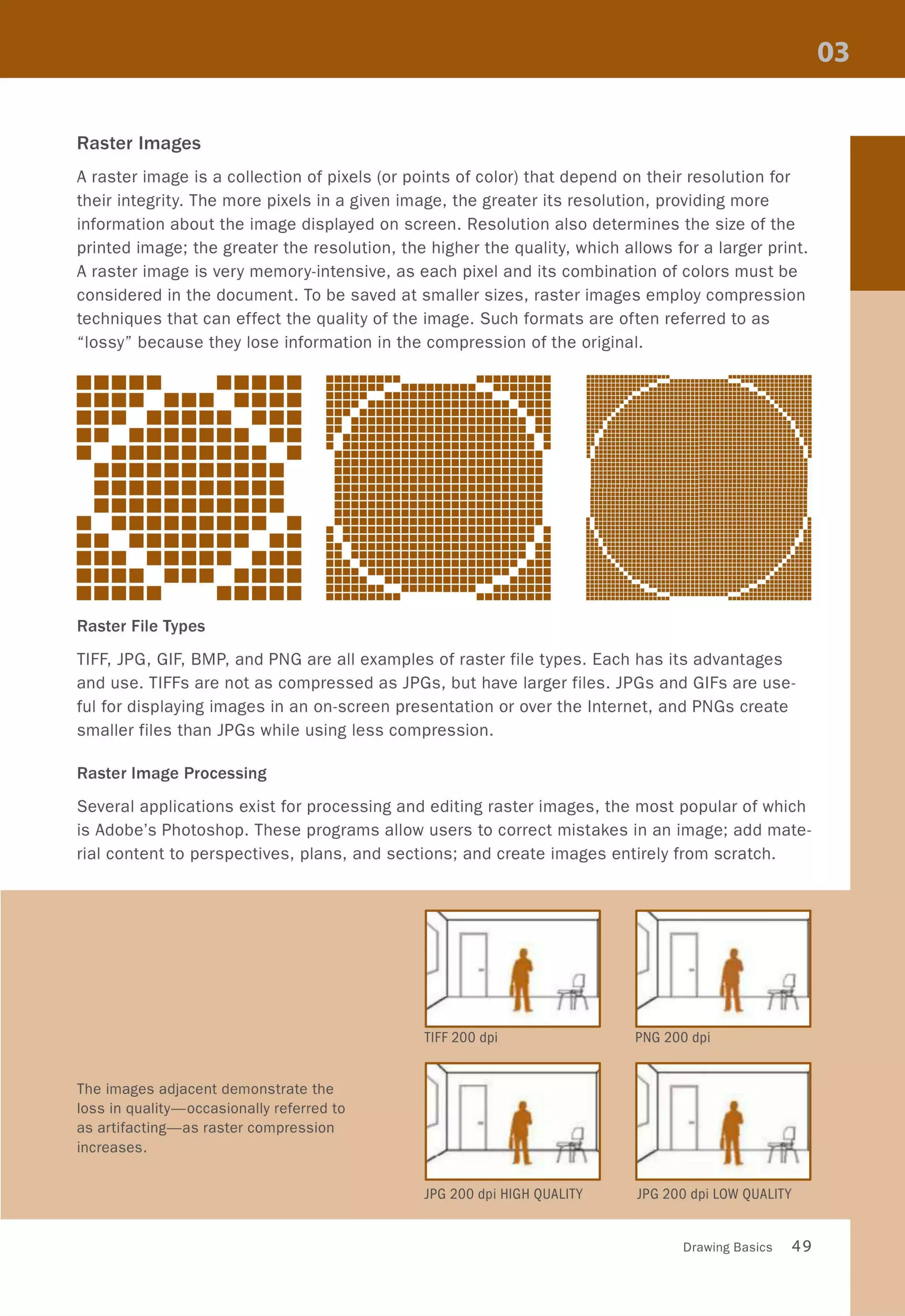
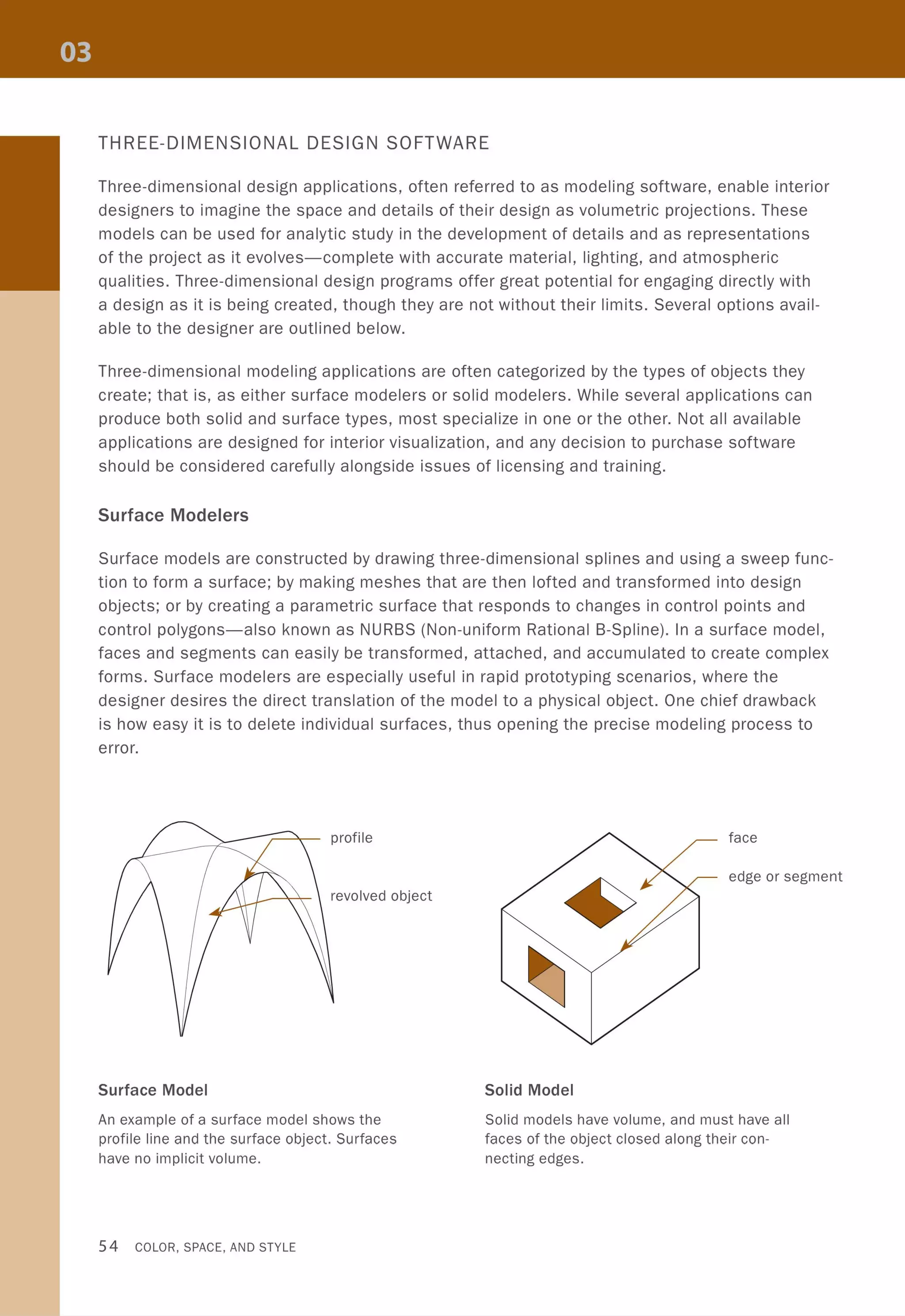
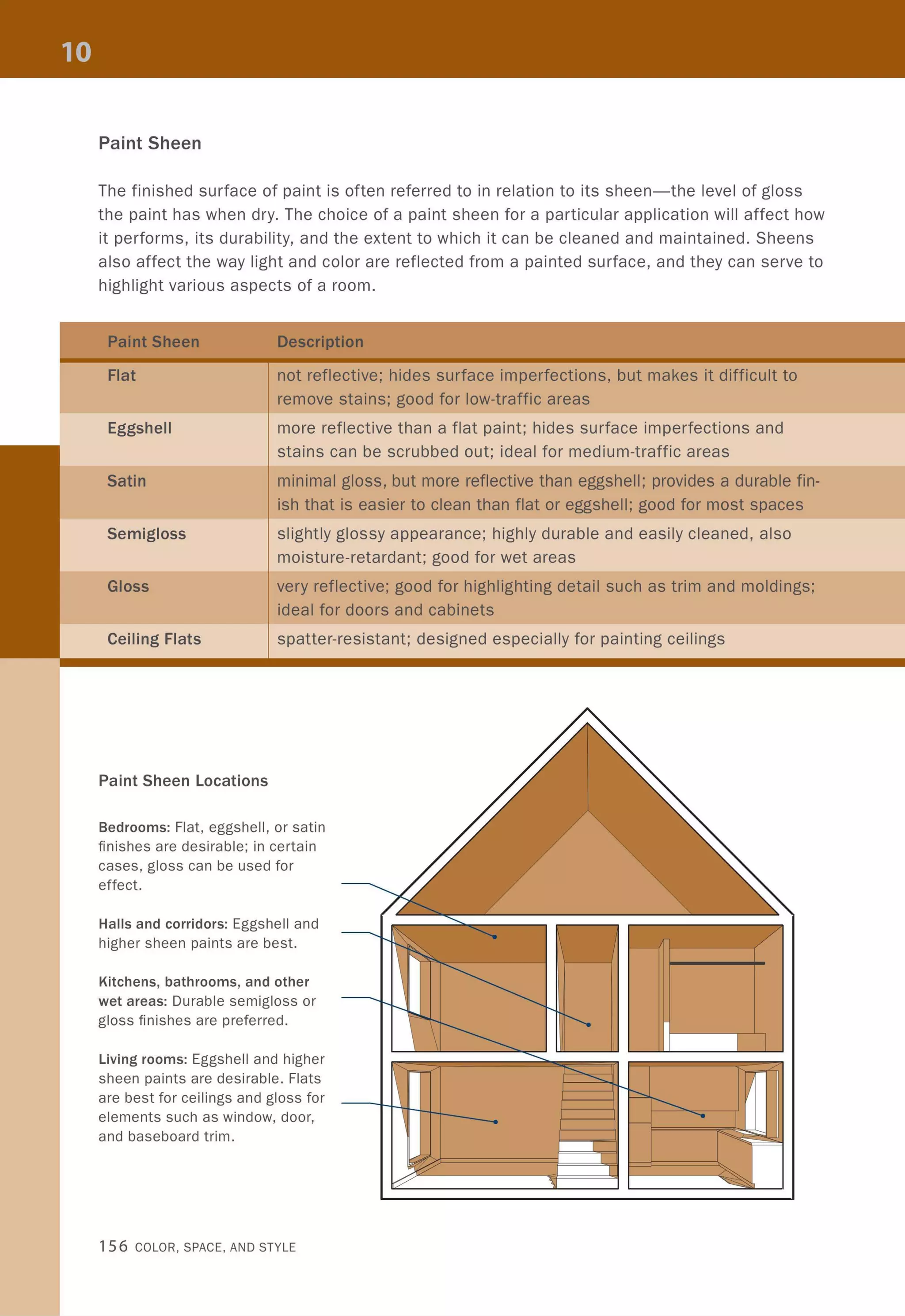
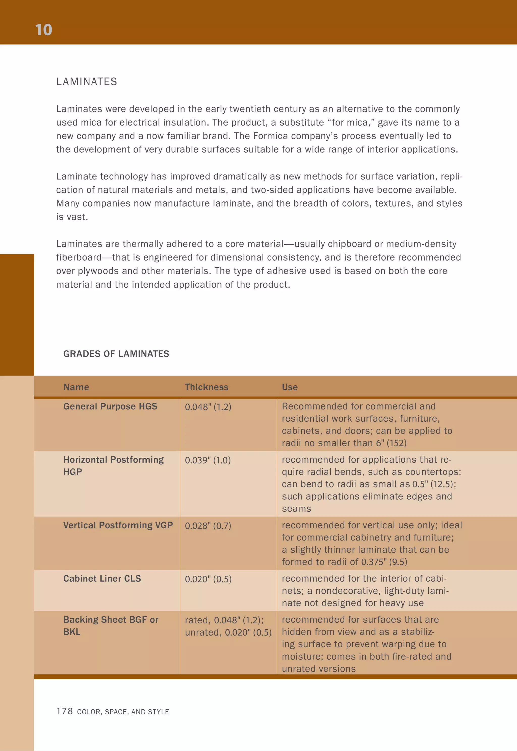
![Chasing the Details
A typical sequence for following the links in a drawing set is illustrated below. A plan drawing
(A) contains information regarding, among other things, an enlarged plan. Navigating to the
cross-referenced sheet (8) indicates a further link to room elevations (C), which are marked
with sectional information found on yet another sheet (D). As with the multidrawing sheet, the
gridded coordinate system allows for more details to be easily added as necessary.
I
A
, ,
I(, ,
"- ~
, ,
, '
,'
0-
- ~
iT,
0
,
,
,
,
-,
L _ _ _ _ _
0- r - - - - - -
,
, -
,
0
,
,
,
-I~
0-
~ J '--
@'SHr"""
c
... --
1
1
1 0
1
o 0 1
1
1
, - - - 1- - - - - -
D
-~--------------- ----------------------~~~~~~----
o o
B
o
I=~~W - - --
,
[[]
Drawing Basics 41](https://image.slidesharecdn.com/colorspaceandstyle-allthedetails-noithat101-170426124809/75/Color-Space-and-Style-43-2048.jpg)


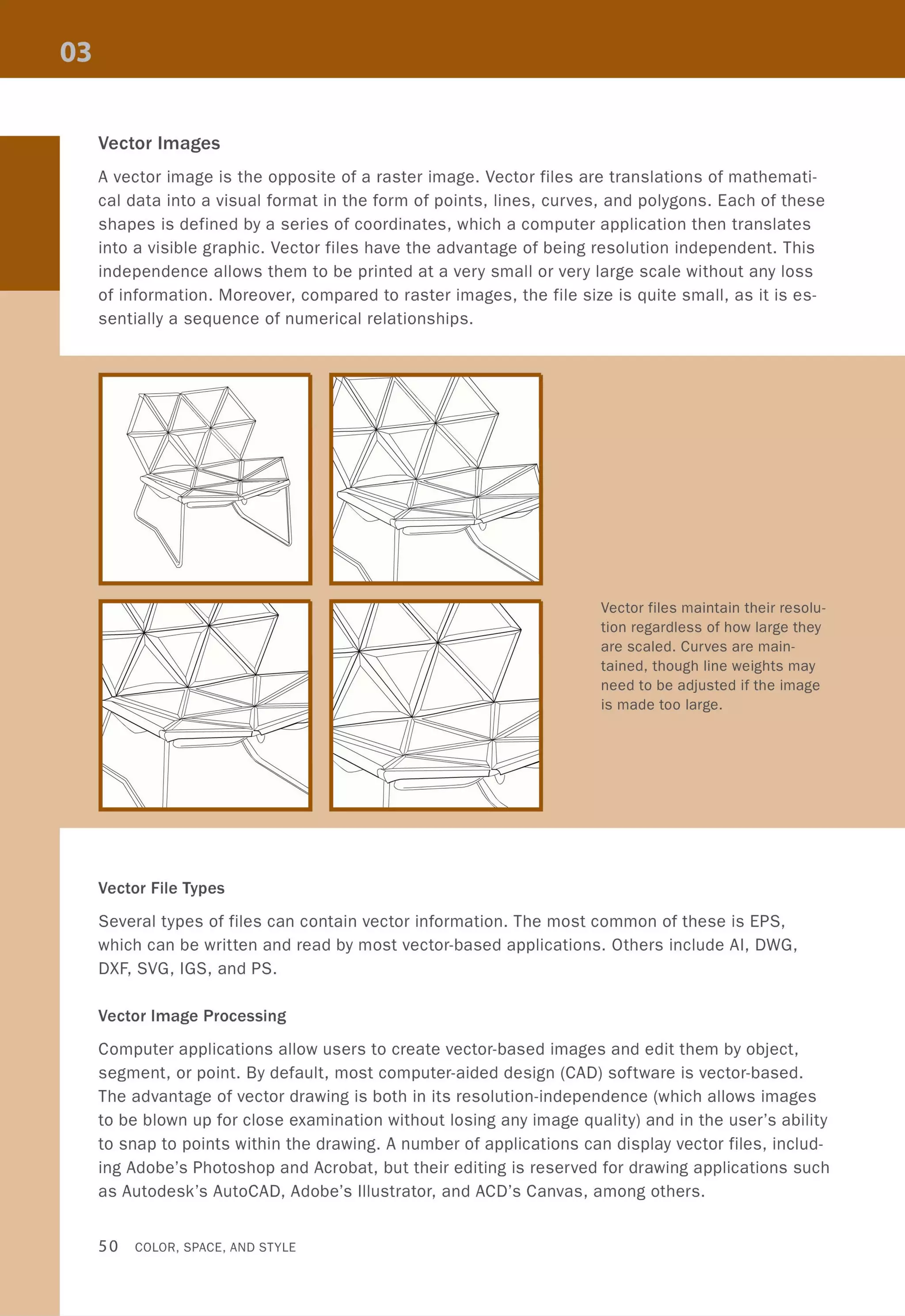

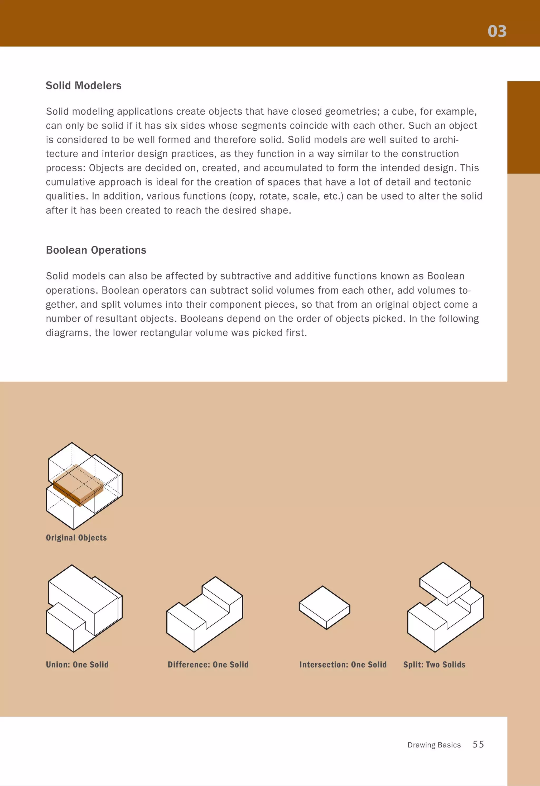


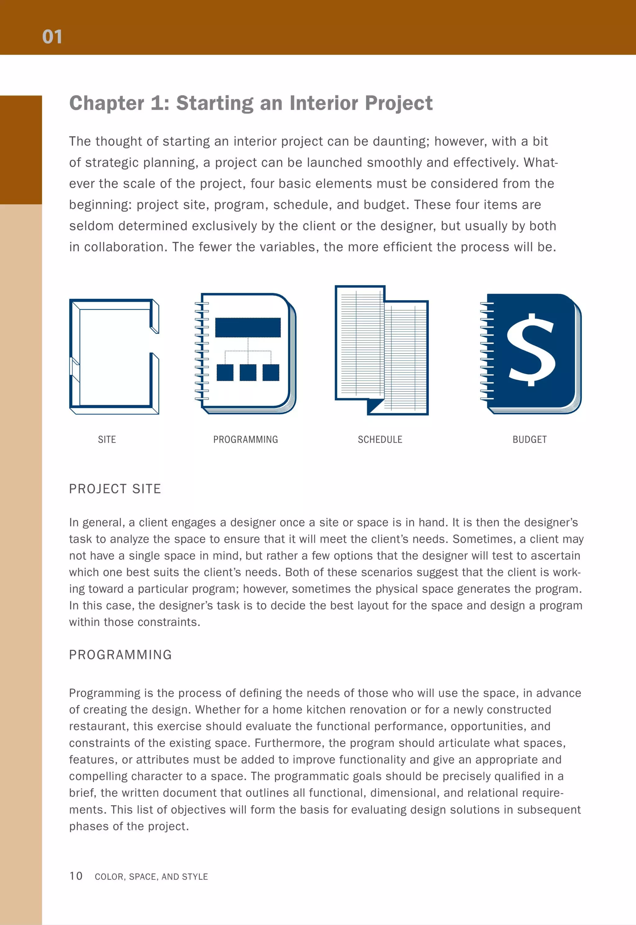
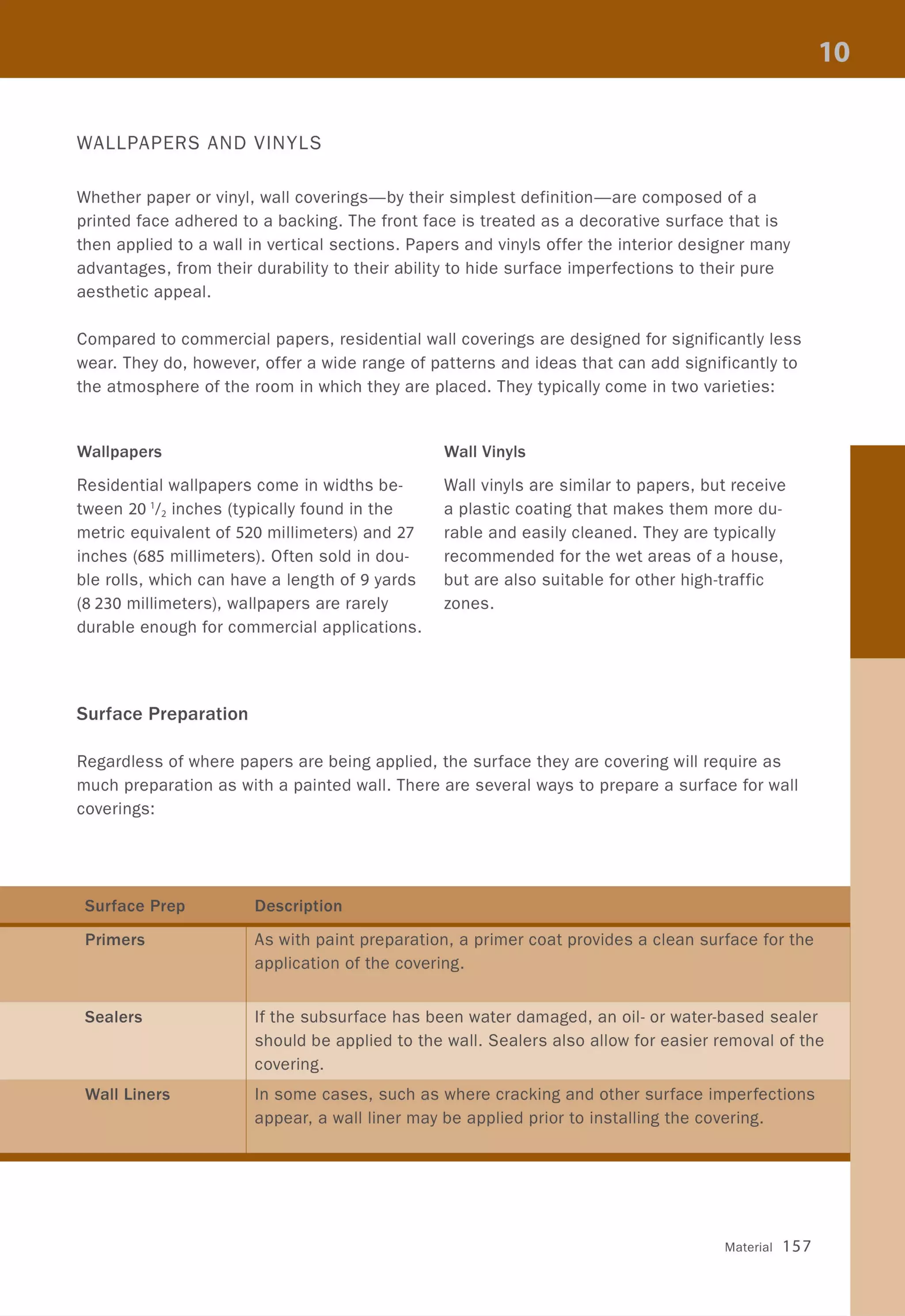
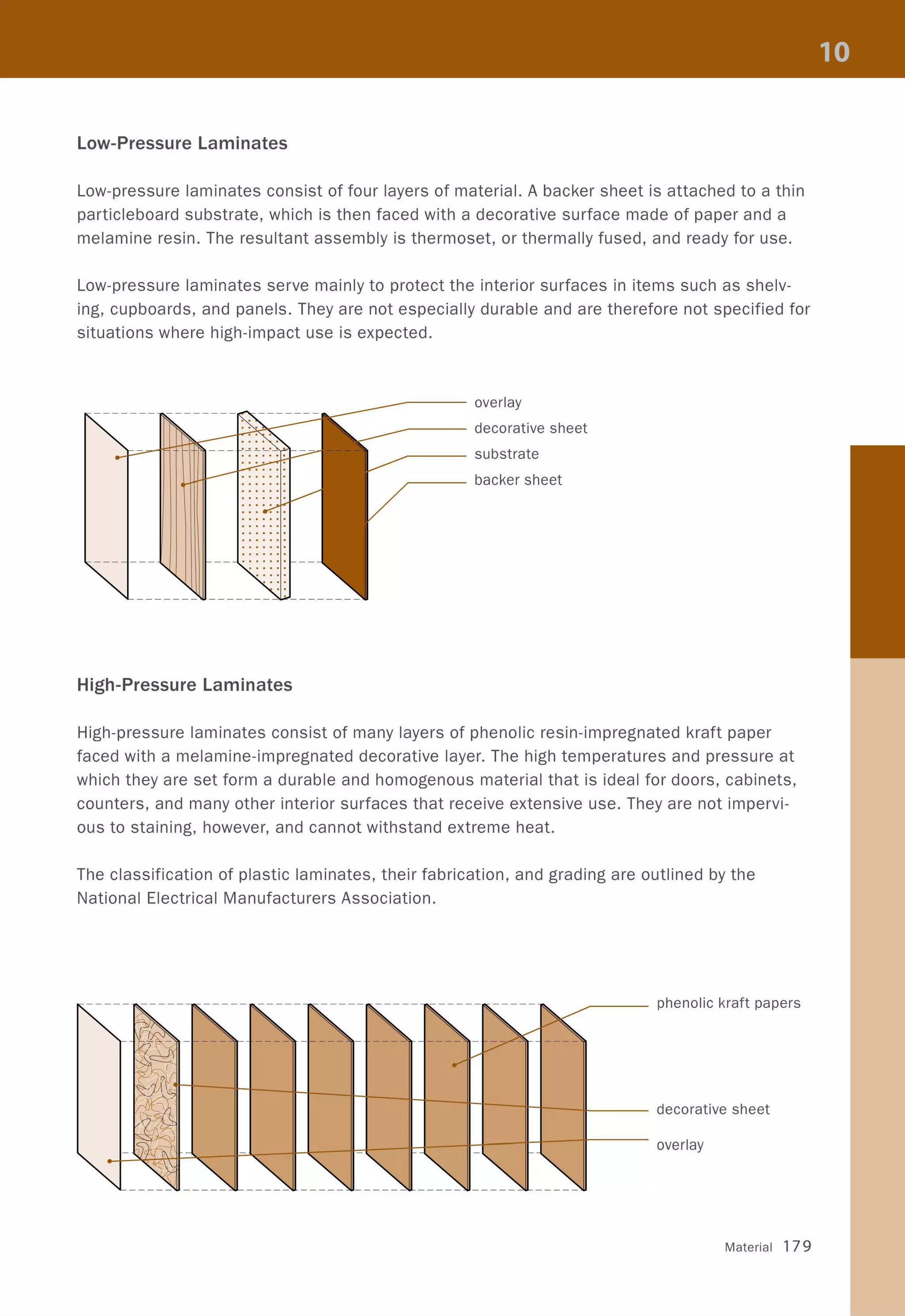
![Typical Office Layouts
Private Office at Window Wall
This layout is typically organized in three layers of functions; starting with a zone of private
offices at the window wall, followed by a zone of circulation, then a zone of back-to-back par-
tial-height cubicles for assistants, and a second zone of circulation against the building core.
Natural light typically reaches the middle of the plan through clearstory windows in the wall
that separates the private offices from the rest of the office space. This layout results in
a conventional dimension from building core to window wall of approximately 45 feet (13.7
meters), which has become the ideal industry standard for the minimum width of American
office buildings.
~ , ,
- LI
<s
~
bl
- LI
<s
,
,
,
~
<s
~
bl
LI
bl
o
, ~-----"-J'
, Y':---""-"
, bl,
,
,
: LI
, ~-----"-J',
, " " I I ' I I
, I , I
r--II---e:::i ~-r----I I-----;:::i ~_~L-_
[] [] [] []
~ ~LI LI
bl bl
LI LI
~ ~
~Y': ~Y': ~Y': ~ Y': ~
0 0 0 0 0 0 0 0 0
'~
,
, ,~~ _L ________________ L _____ _
r , ,
,
90 COLOR, SPACE, AND STYLE](https://image.slidesharecdn.com/colorspaceandstyle-allthedetails-noithat101-170426124809/75/Color-Space-and-Style-92-2048.jpg)


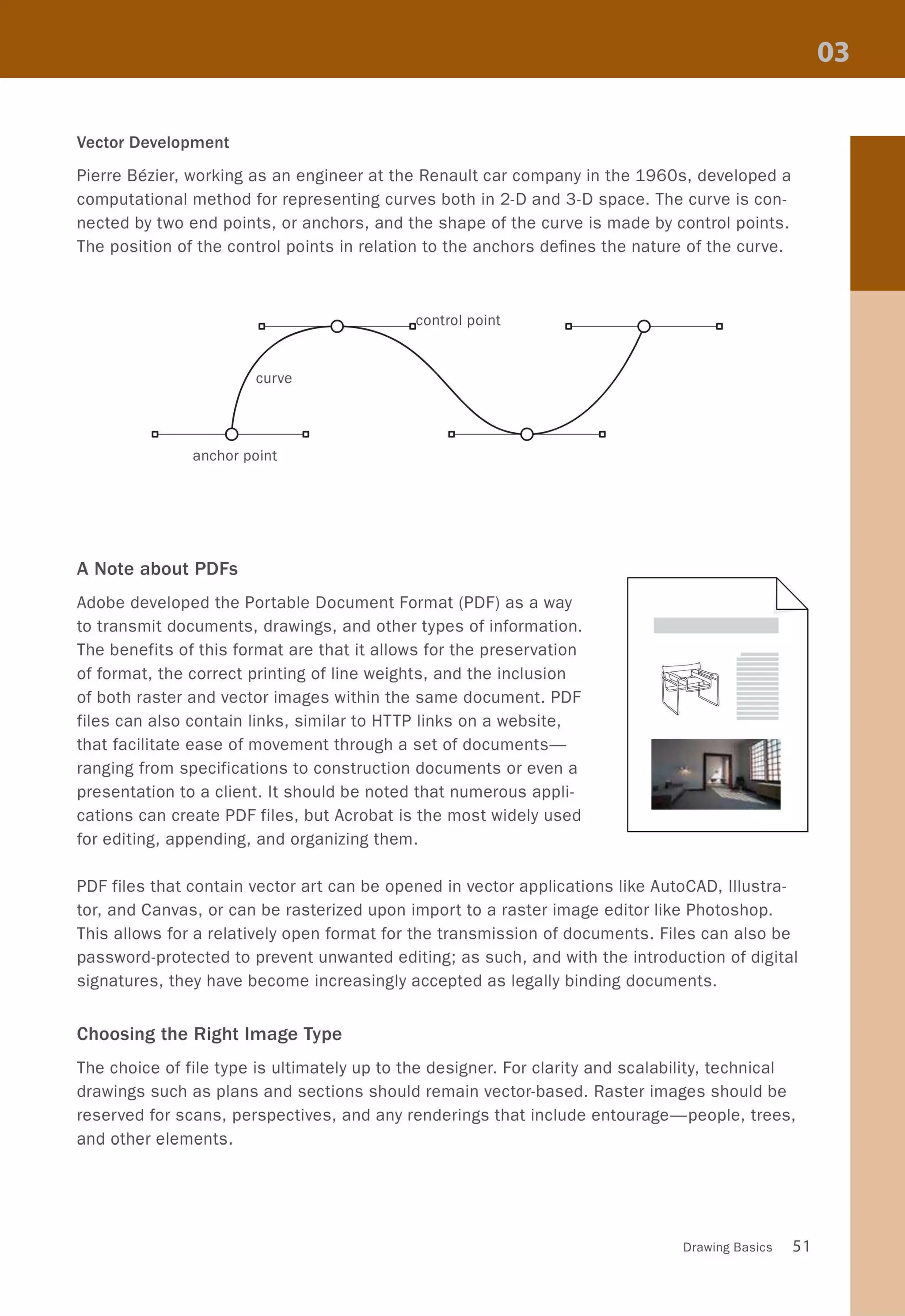
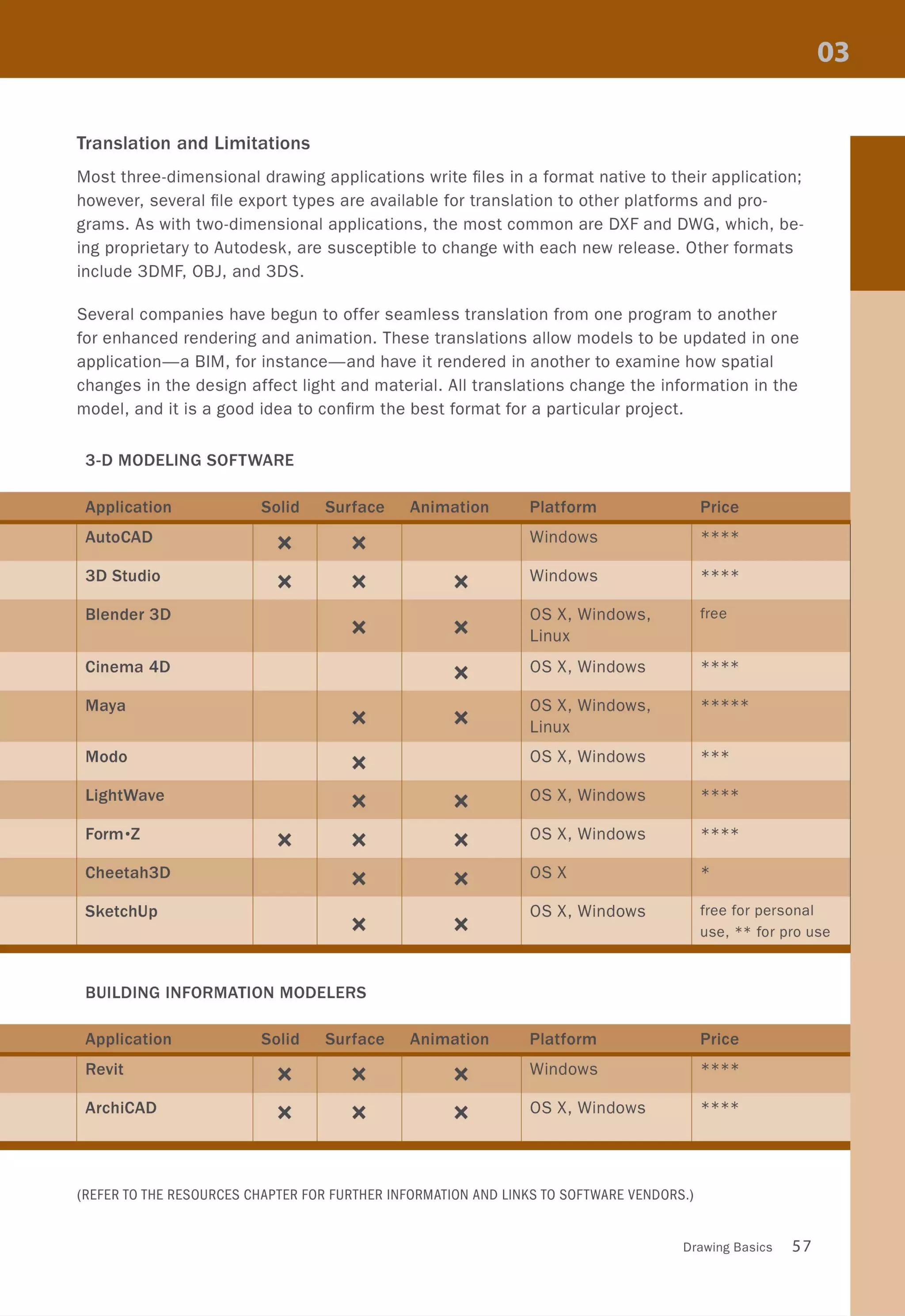
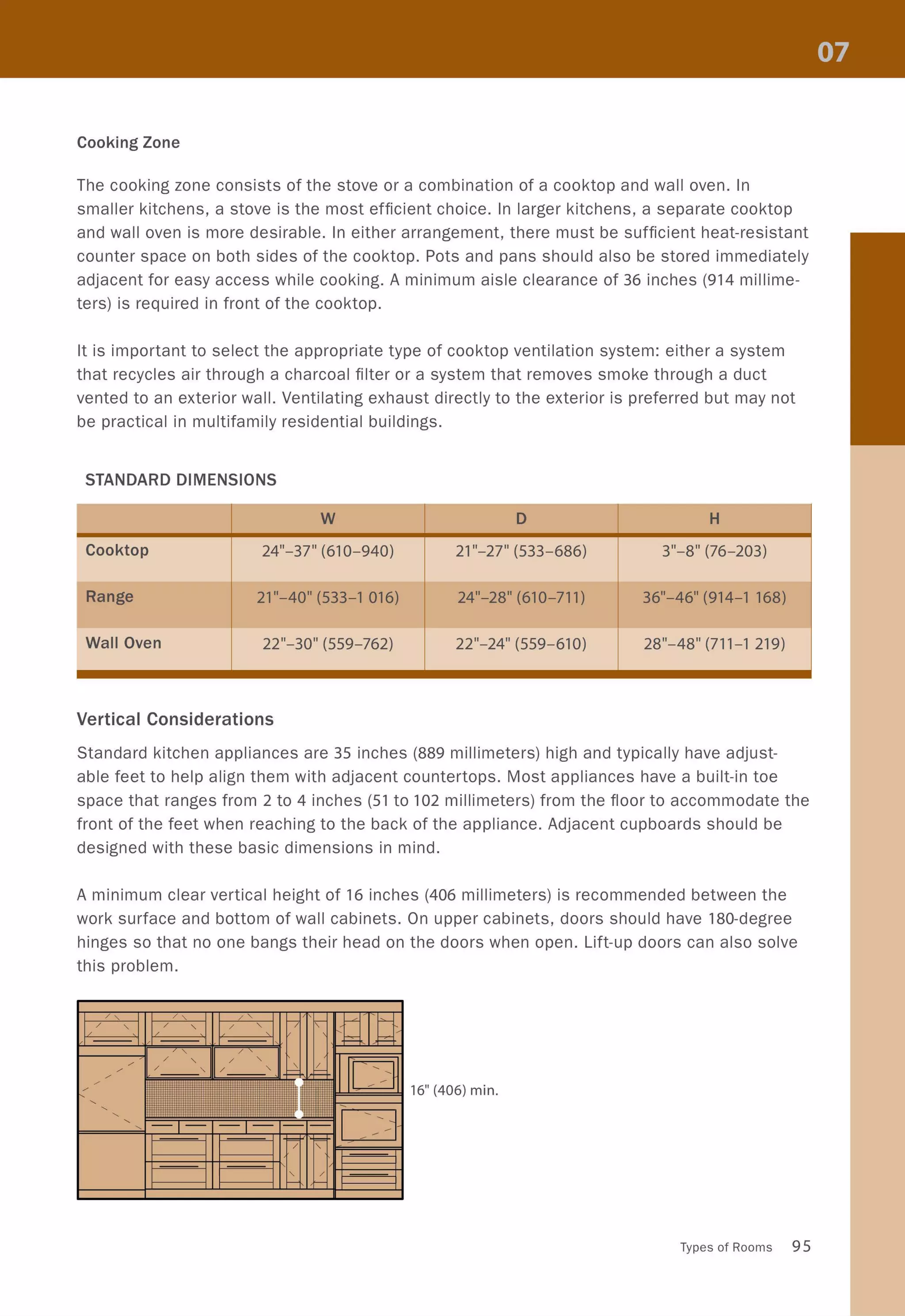
![Kitchen Layouts
Single-Wall Kitchen
The simplest kitchen organization is a single row of appliances and
counter space arranged against a wall. This layout is ideal for long
narrow rooms or one wall of a studio apartment where the kitchen
can either be screened off or made the central focus of the space.
The most practical plan should include counter space on both sides
of each major appliance. The refrigerator should be placed at one end
of the kitchen wall since it only needs counter space to one side-re-
member to specify a refrigerator with doors that open in the direction
of the adjacent counter space.
Galley Kitchen
A galley kitchen has two parallel runs of counters. The sink, dish-
washer, and stove should be located on the same side of the kitchen
(cooking and washing zones) and the refrigerator (the preparation
zone) should be located on the opposite wall. The counters should be
at least 4 feet (1 219 millimeters) apart to provide adequate room for
more than one cook; if the kitchen is designed for only one cook, the
space between counters can be reduced to 3 feet (914 millimeters).
This layout is not recommended if other rooms are accessed through
the kitchen.
L-shaped or U-shaped Kitchens
In these layouts, the counters and appliances are organized around
two or three walls. This arrangement can work in either small or large
spaces; however, in larger rooms the working triangle should be kept
within the optimal range of 12 to 22 feet (3658 to 6 705 millimeters).
Often in these arrangements, one leg of the L or the U forms a counter,
which is ideal for casual meals. In this scenario, it is best to design a
higher counter to separate the cooking zone from the eating zone.
Island Kitchen
A central workstation provides extra space for performing various culi-
nary tasks. Depending on the preferences of the cook, the island can
be designed for either preparing or cooking a meal. Of all the layouts,
this arrangement encourages the most socializing in the kitchen. It is
best used in large rooms that allow enough space between counters
and island.
••••
(]
~
••••
[]
••••
••••
93](https://image.slidesharecdn.com/colorspaceandstyle-allthedetails-noithat101-170426124809/75/Color-Space-and-Style-95-2048.jpg)

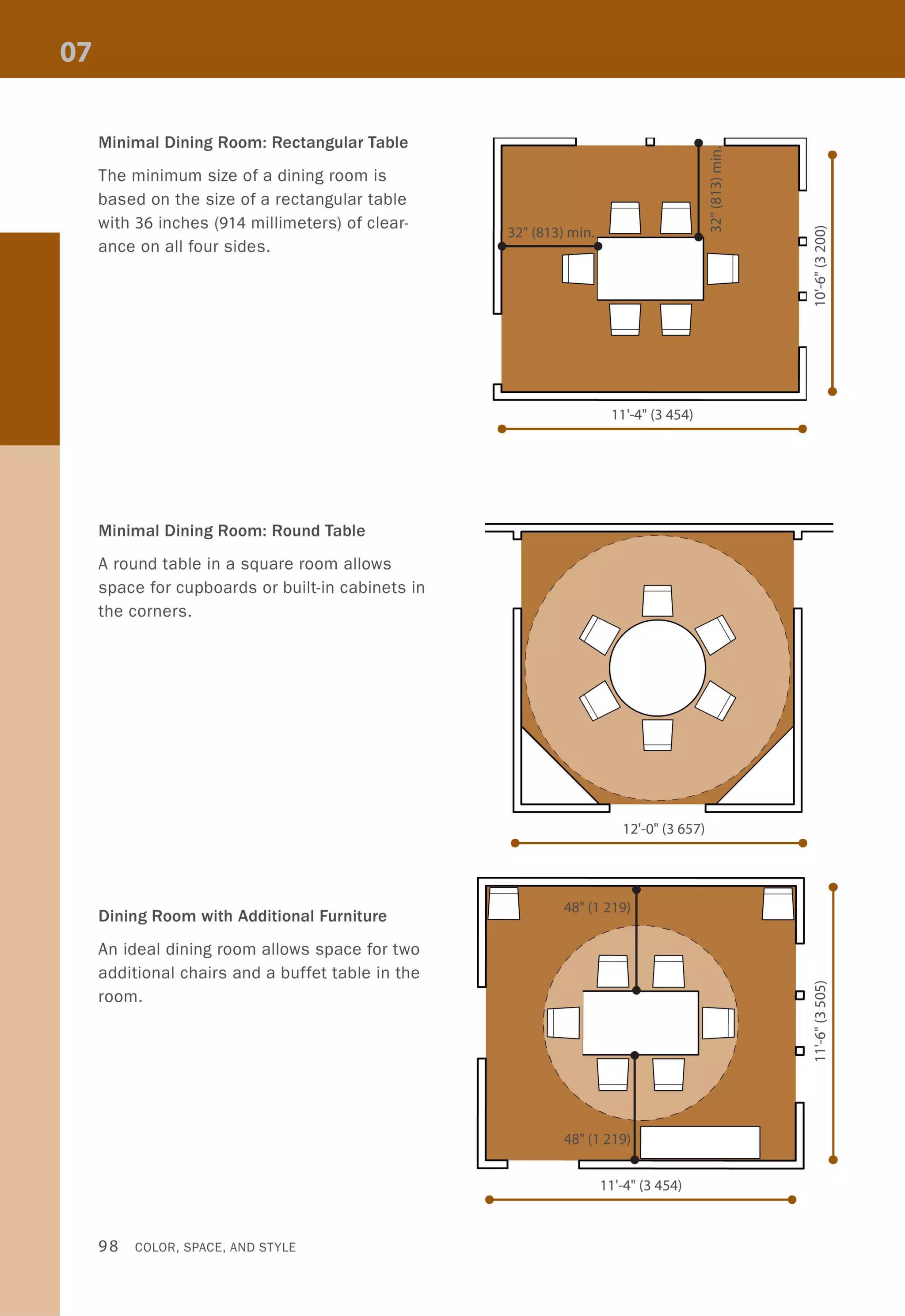
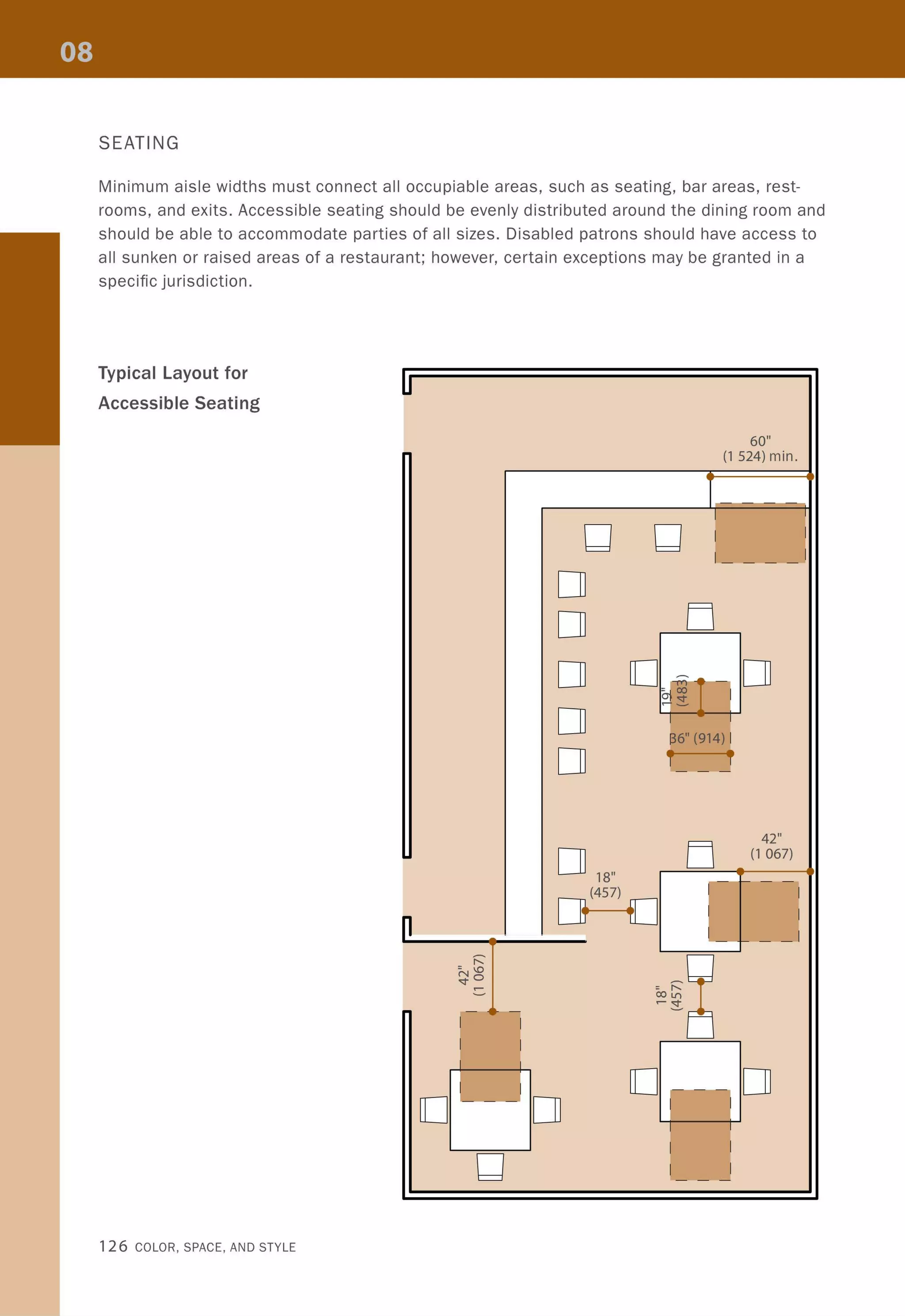
![Dining Room Layouts
The size and shape of a room can help to determine the best table configuration for a specific
situation. The diagrams that follow look at dining rooms combined with a living room or kitchen
as well as dining rooms of minimal dimensions. In addition to tables and loose furniture, in-
terior designers must consider the ambience of a room by including adjustable lighting above
the table and near the serving area.
[] []
32" min.
U U(813)
[J []
Cd Cd
D
48" min.
(1 219)
[]
00
00
[J
[J
Combined Dining and Kitchen
Kitchens with an eat-in dining table
require additional space adjacent to the
work zones.
Combined Dining and Living Room
When space is at a premium, combining
the dining and living rooms may be
better than isolating them into separate
smaller rooms.
[]
[]
Types of Rooms 97](https://image.slidesharecdn.com/colorspaceandstyle-allthedetails-noithat101-170426124809/75/Color-Space-and-Style-99-2048.jpg)
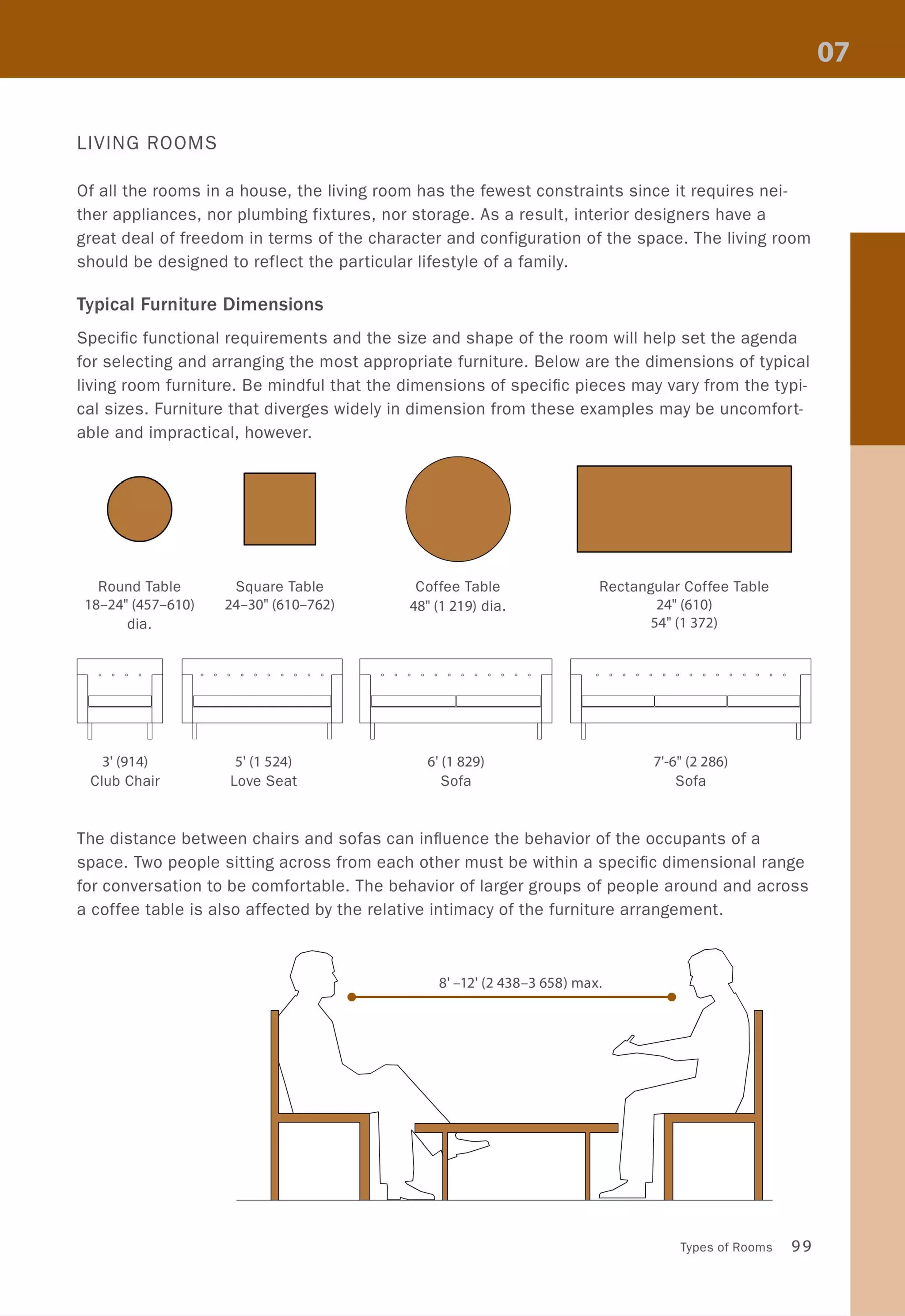
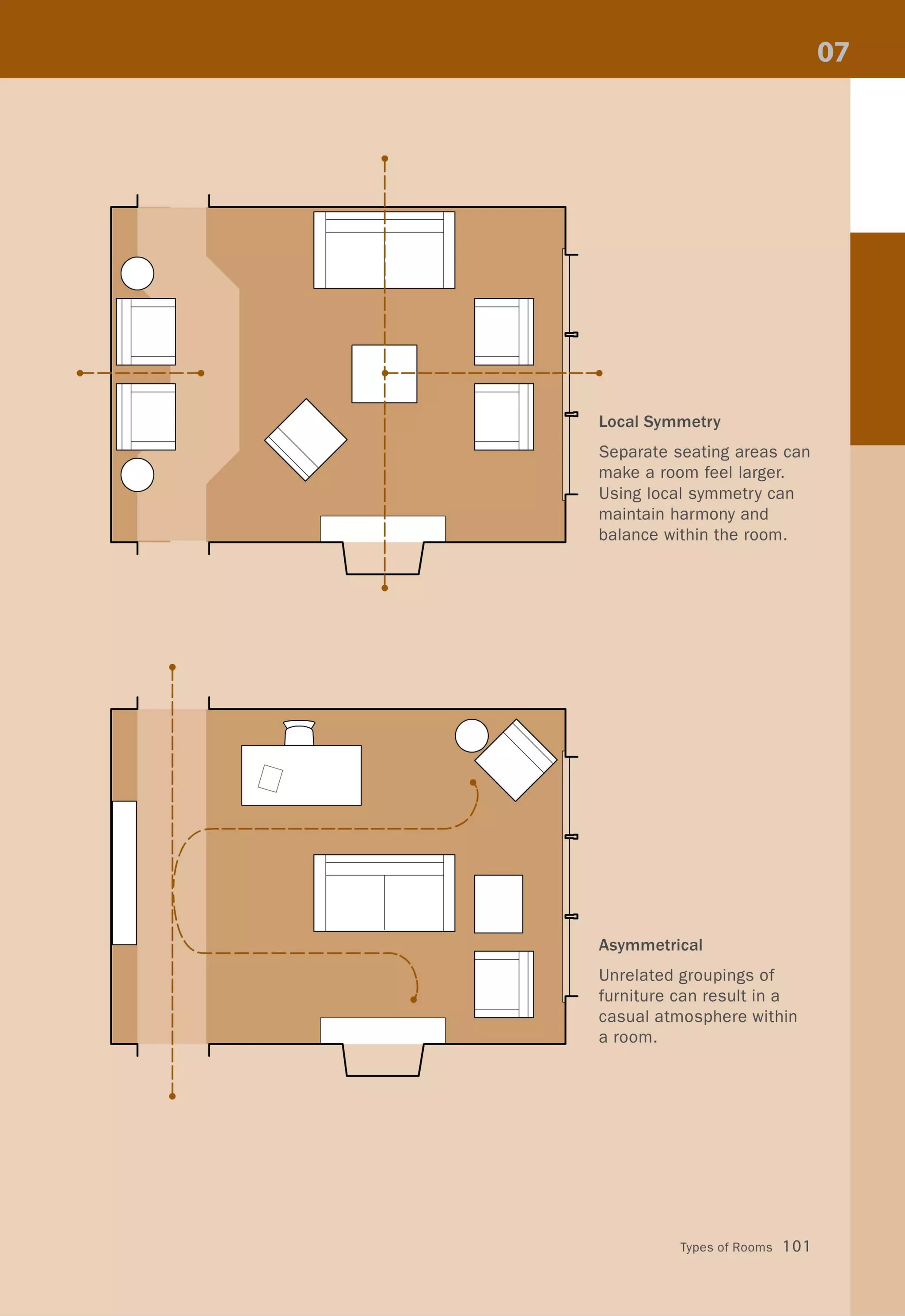
![Living Room Layouts
A typical living room can
function well when ar-
ranged according to sev-
eral alternative principals.
Symmetrical
Using the natural center of
a room, furniture is placed
around a common axis.
Dual Axis
A cross axis will focus at-
tention toward the center
of a room, while other fea-
tures become a backdrop.
100 COLOR, SPACE, AND STYLE
I
U
[]
[]
I
I
I
D
--- --.-
DI
T
II
iI
i
I
!
i
I
I
I
I
!
i
I
I
I
I
!I
T
I
II
i
I
-+-
I
!
i
I
I
I
I
I
I
~
U ;-
~
?
l-
I
I
I
D ;-
?
r - - -
-~
I-
l D](https://image.slidesharecdn.com/colorspaceandstyle-allthedetails-noithat101-170426124809/75/Color-Space-and-Style-102-2048.jpg)
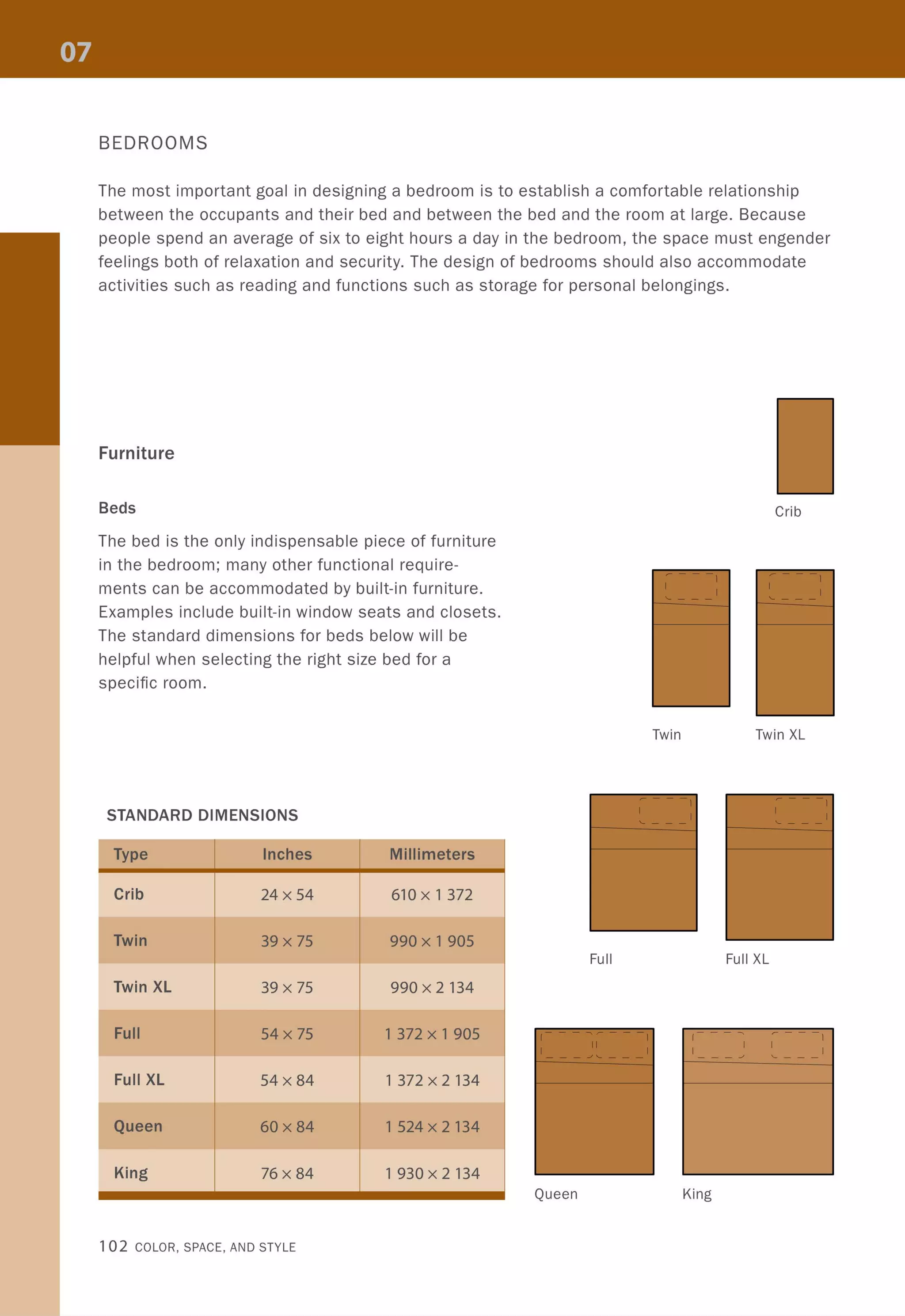


![MINIMUM TABLE DIMENSIONS
Shape
Square
Square
Round
Round
Round
Rectangular
Rectangular
Rectangular
24"(610)
• •
Seats
2
4
4
6
8-10
4 (2 per side)
6 (3 per side)
8 (2 per side)
b r - '
~4
~
1 (]'I
N
~
(]'IN (V")
1 1 = '<I"
~O = 00
I.I)~
(V") 00 r-..r-.. '<1"1
1 1 ~
_I r-..
= 0 ~ - 0
O~ NO
(V")~
T
'<I" ~
~
Working Counter
------,
I I
I
IL _ _ _ _ _ _
II
Standing Counter
---.....-"""''''''"~''''''''-
W L
24",30" (610, 762) 24",30" (610, 762)
36" (914) 36 (914)
36"-42" (914-1 067) dia.
42"-48" (1 067-219) dia.
66" (1 676) dia.
30" (762) 42"-48" (1 067-219)
30"-36" (762-914) 72"-84" (1 829-2134)
36" (914) 90"-106" (2 286-692)
28"-38"
(711-965)
• •n
~
, (V")
~
= '<I"0 I.I)~
~
'<1"1
0 _I r-..~
- 0
~
NO
~
'<I"
N ~
~
Dining Counter
60"-74" (1 524-880)
• • 4
24"-30" (610-762)
• •
r-.. a1.1) ~
'<I"
~
=00 0~
(V")
I
Banquette
These sections describe ideal vertical dimensions. Please note that all vertical dimensions
are subject to local building code and accessibility regulations.
Types of Rooms 109](https://image.slidesharecdn.com/colorspaceandstyle-allthedetails-noithat101-170426124809/75/Color-Space-and-Style-111-2048.jpg)
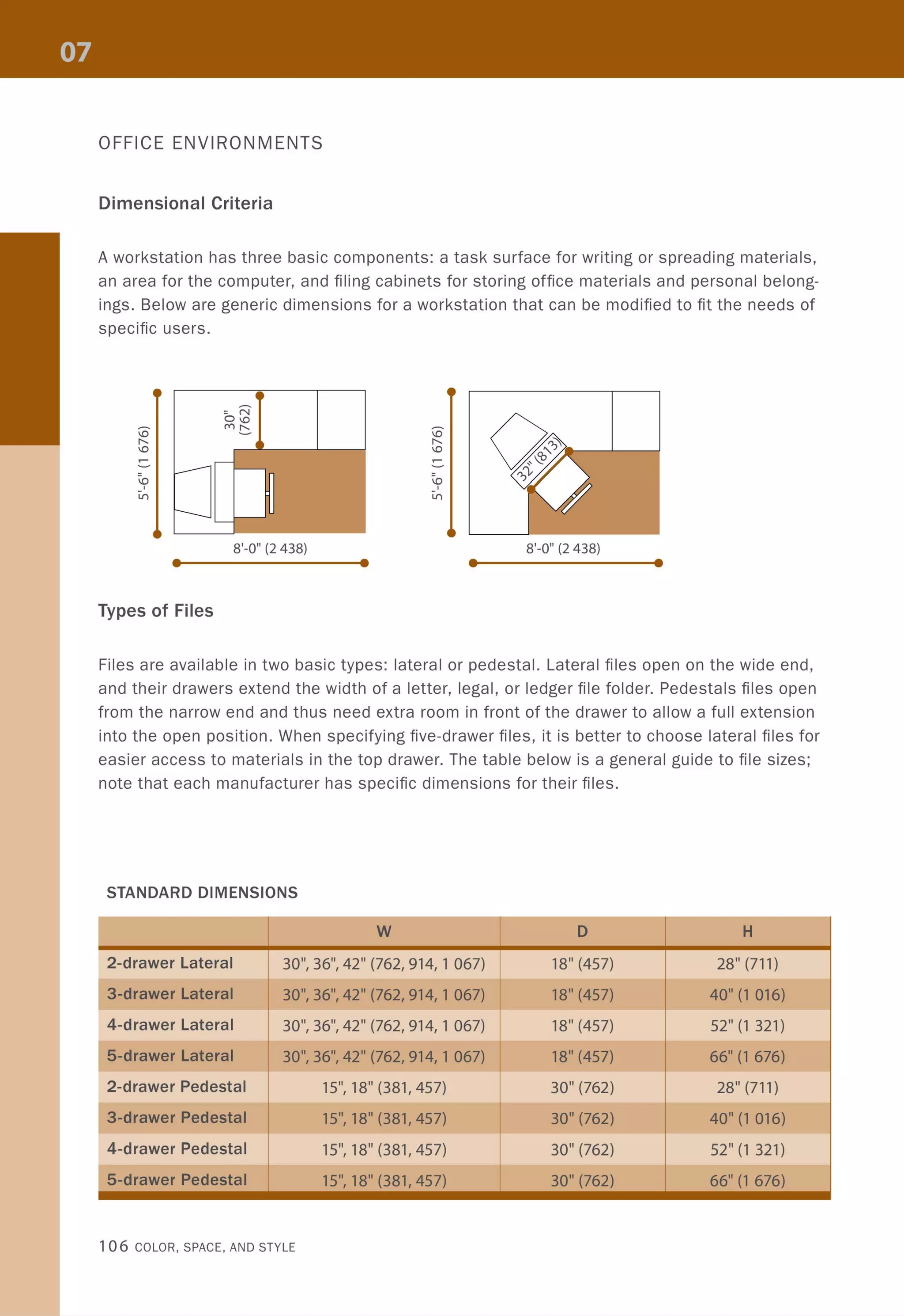
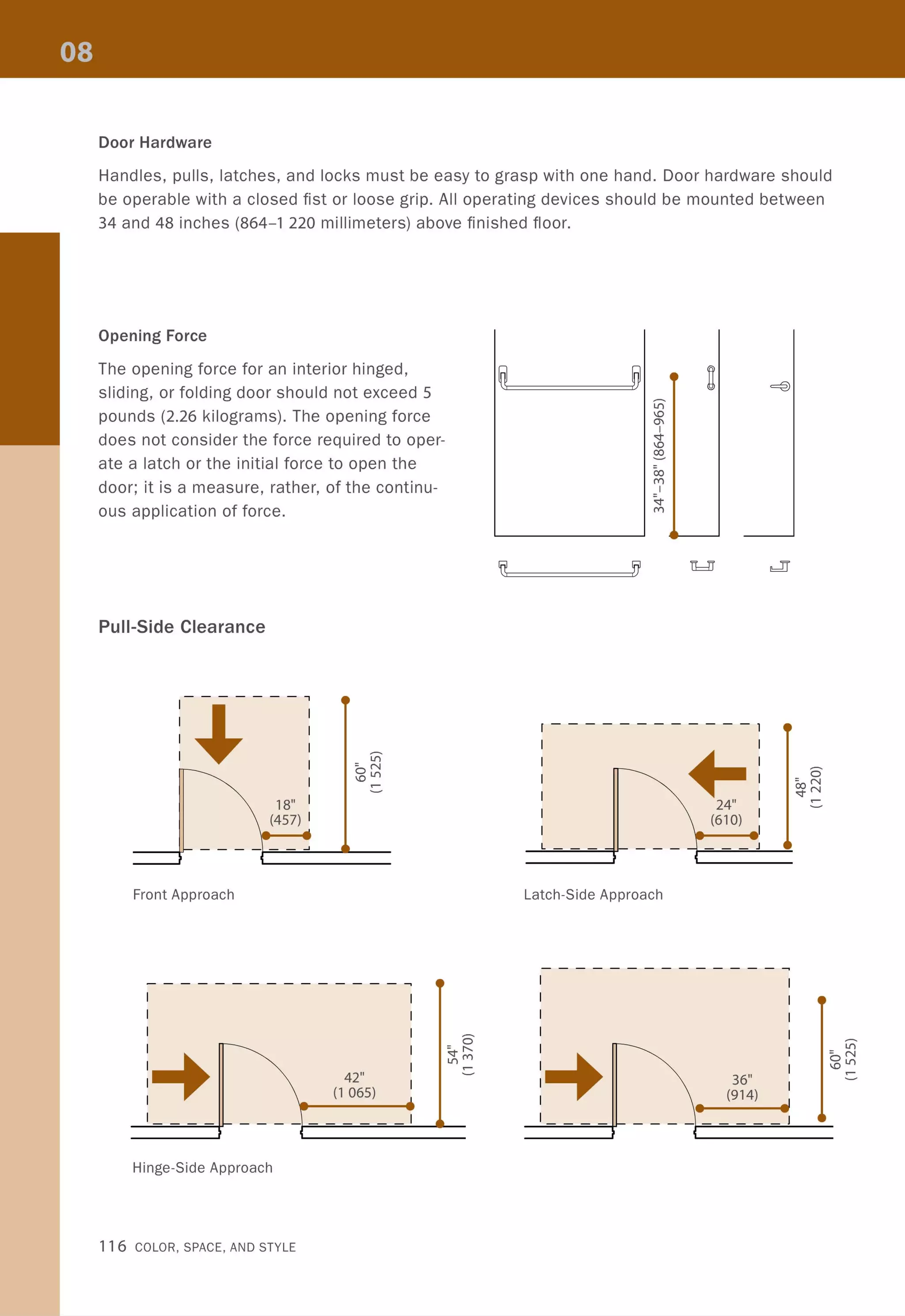
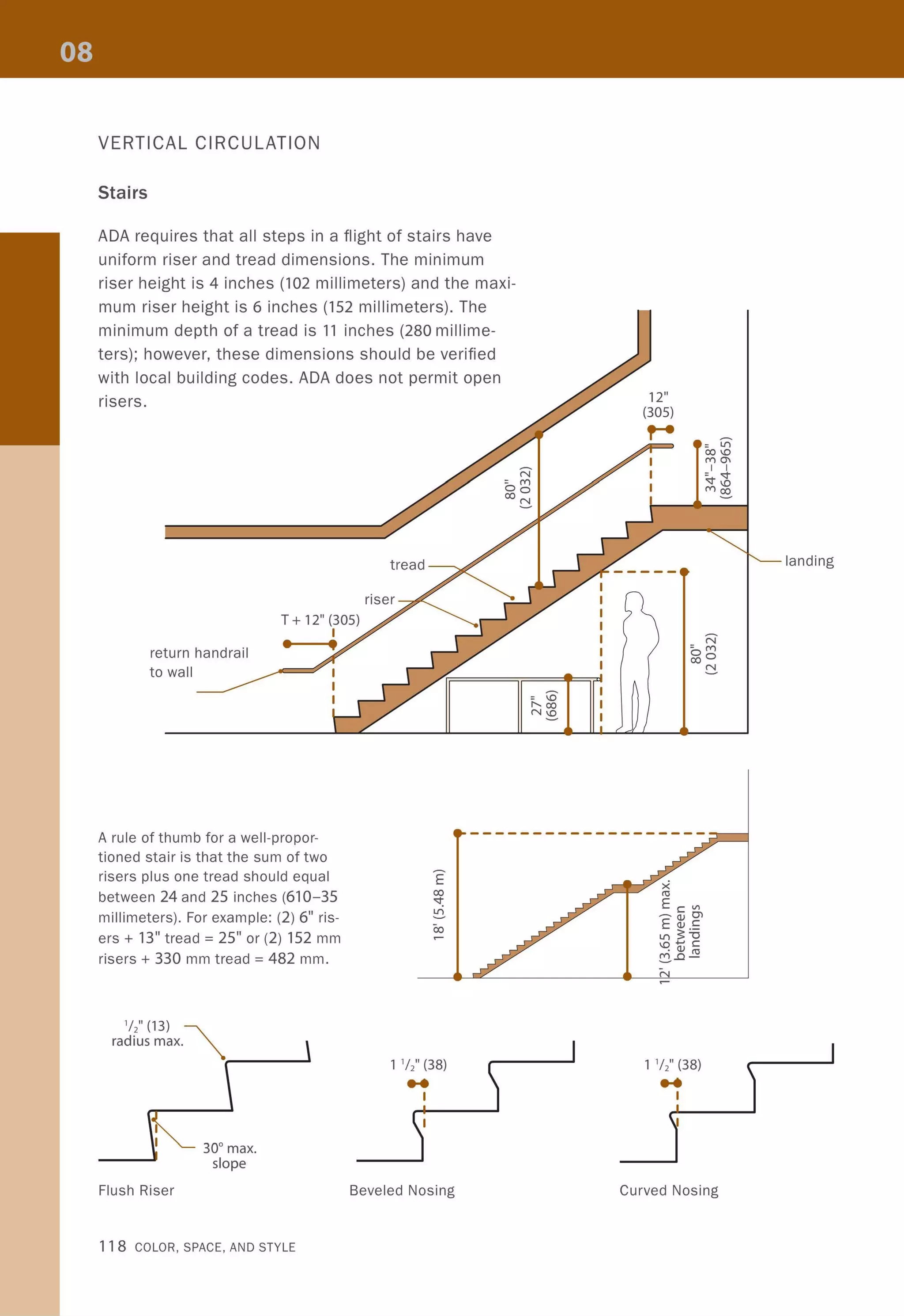
![DOORS
Clear Opening
The minimum clear opening width is 32 inches (813 millimeters) measured with the door open
in a 90-degree position. The measurement should be taken from the face of the door to the
stop on the strike jamb. For bifold, accordion, and pocket doors, the clear widths are mea-
sured when the doors are in a fully opened position. No projections are allowed in clear open-
ing space, with the exception of door hardware.
For double doors, one leaf must comply with the minimum clear opening. Shallow closets
that are less than 24 inches (610 millimeters) deep are exempt from the minimum clear width.
Doors that are recessed more than 6 inches (152 millimeters) from the door opening need to
comply with pull- or push-side requirements.
r-----' 32" (813)
I ••~I____~~__••
I I
--
I I
..:J'": -""'l :
~-~--~- ~
An offset pivot allows a door
to swing clear of the frame. Offset Hinged Door
•I
I
I
:::::J
32" (813)
Pivot Door
Thresholds
The maximum height for a threshold
is a half inch with a slope no greater
than 1:2. Half-inch (12.7-millimeter) pile
carpet is the maximum allowed.
•
• 32" (813)
•
Hinged Door
32" (813)
• •I I
I I
I I
~~__----{C~IC=
Pocket Door
32" (813)
• •I I
I I
:]11~~~~:: :~-----4C=
Sliding Door
2
1 CC~::~~~~~__________
"SJU11T'' S'' S' ''''1
W' (12.7)
Code and Accessibility 11 5](https://image.slidesharecdn.com/colorspaceandstyle-allthedetails-noithat101-170426124809/75/Color-Space-and-Style-117-2048.jpg)


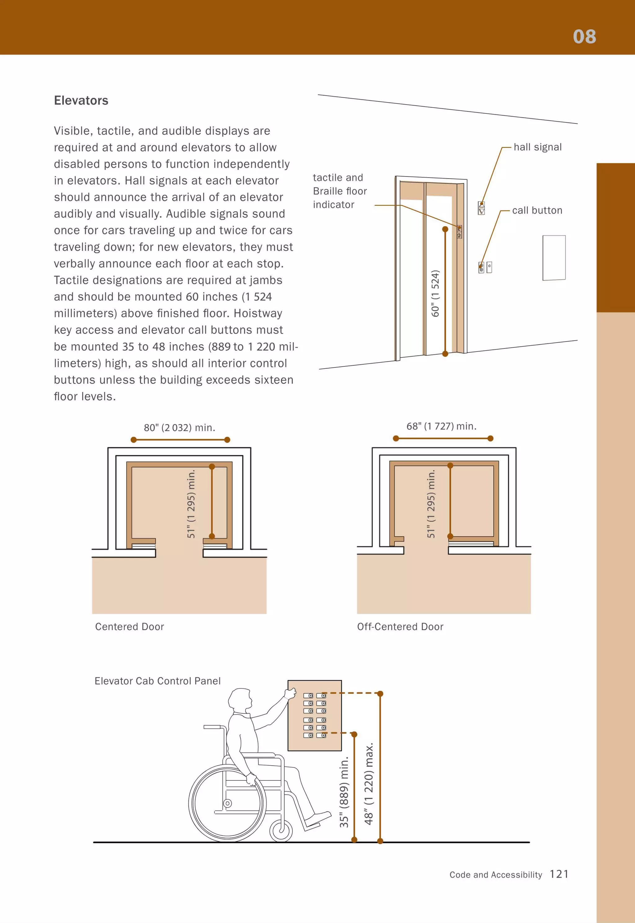

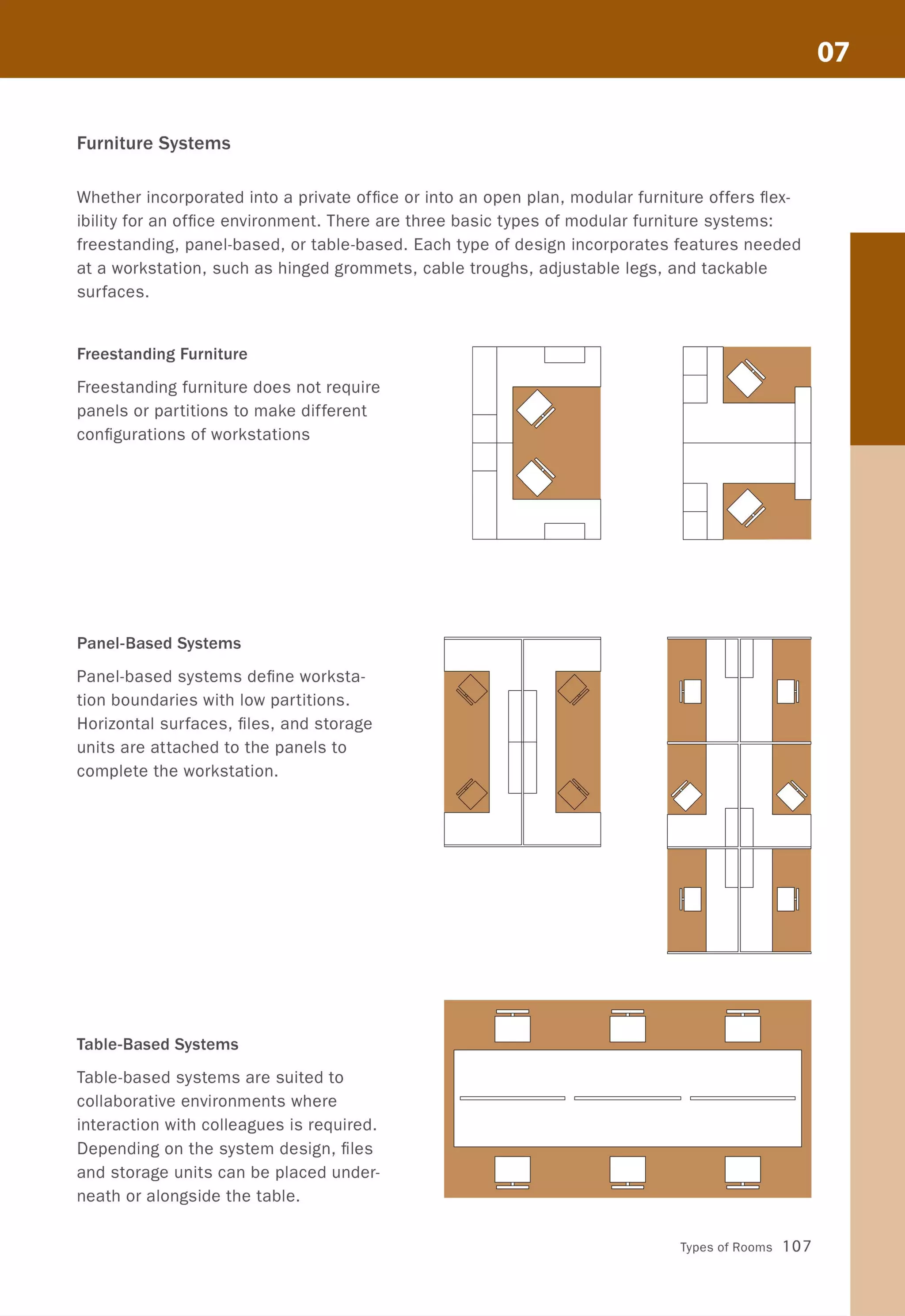
![Lavatories
L ____ :- _ ~
I I
I I
I I
I I
19" (483) max. I II I
• •
Showers
•I
Bathtubs
" 1If +-'
0 co
(])
I.....
U)
V
30" x 60" (762 x
1 524) min. clear
floor space
12" (305)
max.
24" (610)
min.
- -
~ <&
"
<!: :il
36" (914)
0
cr
(,
><
r----"-'I----------c::------~-- co
C .- co E
~'*' -.------E--- E
~~.).. E ~ ~
~ 0 M
0"1 00 0
_______......:::~~:::......~~--..:.7-----.f_-~f~]-~-- ;I : I I
...... ~ ~ 6" (152) max.
I ! 17" (432) min.v
.•- -........
6" (152) max.
• 60" (1 524) min .I
C
,
~
E
'<t ~
~ N
0"1 0
"-~
0
0M
M
"(
"+-'
0 co
(])
"--
U)
../
48" x 60" (1 220 x
1 524) min. clear
floor space
12" (305)
max.
=~O~
MO"I
I I
= 00
MM
MOO
~
~
o
-
«
<!:
•
"/
0
1"-.
15" (381)
• •
+-'
co
(])
U)
30" x 75" (762 x 1 905)
min. clear floor space
48" (1 220)
min.
-
:il
:il
Code and Accessibility 123](https://image.slidesharecdn.com/colorspaceandstyle-allthedetails-noithat101-170426124809/75/Color-Space-and-Style-125-2048.jpg)
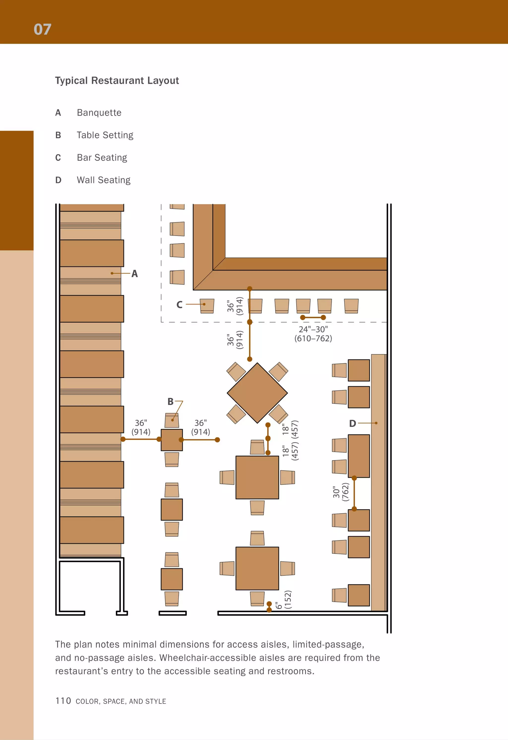
![KITCHENS
When designing a kitchen for a multifamily dwelling, interior designers must determine the
jurisdictional requirements for their specific project because they can vary depending on the
type of project and the number of units. The layout for an accessible kitchen follows the same
principles as that of a standard kitchen, with additional criteria regarding maneuverability. In
general, clear floor space is required at fixtures and appliances, and the shape and size will
depend on whether the approach is parallel or perpendicular.
• • 1
1
1 1
•• 1 1
I I
EJ 60" (1 524) min.
- - - -
40" (1 016) min.
[]- - - -
1- - - -
••••
- - -
Galley Kitchen U-Shaped Kitchen
1
136" (914) 1 1 60" (1 524) min.
1
I _______ J
Front Approach
124 COLOR, SPACE, AND STYLE](https://image.slidesharecdn.com/colorspaceandstyle-allthedetails-noithat101-170426124809/75/Color-Space-and-Style-126-2048.jpg)
![r-
/
]] ]]I']
]
1 I ~
-
.... :---:CIJ
c
0
FJ
:- :
.0 : --~
ro
u -'+-
0 iC.-
E I
0 = - I........0
.0
0
~
=--;T ---....
r,~ "~
~
Lf)
0-
N
~
~
=~
Lf)
'r ~ I~.L )-- c-
§ : ~'~ ,~. t ~ ---... =.J :!:, ~- ~
-"-----,J
- ® ~ ~/ '
~ "'--
Adaptable Kitchen Design
Depending on the specific project, a kitchen
might be designed as "adaptable," meaning
that certain features can be adapted for per-
sons with or without disabilities. Examples
of adaptable features are removable base
cabinets for clear knee space and adjust-
able counter heights.
/
]
I
34"
(864)
~
-
.....
-
hood controls
perpendicular
roachapp
retractable
ad boardbre
clear knee space
-
Code and Accessibility 125](https://image.slidesharecdn.com/colorspaceandstyle-allthedetails-noithat101-170426124809/75/Color-Space-and-Style-127-2048.jpg)


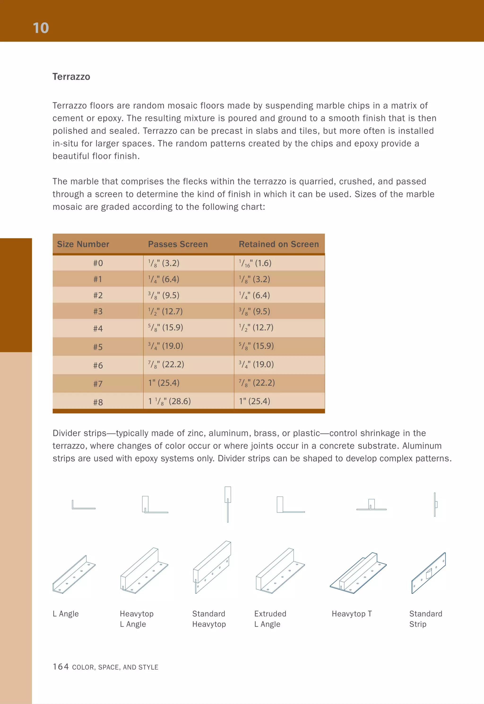
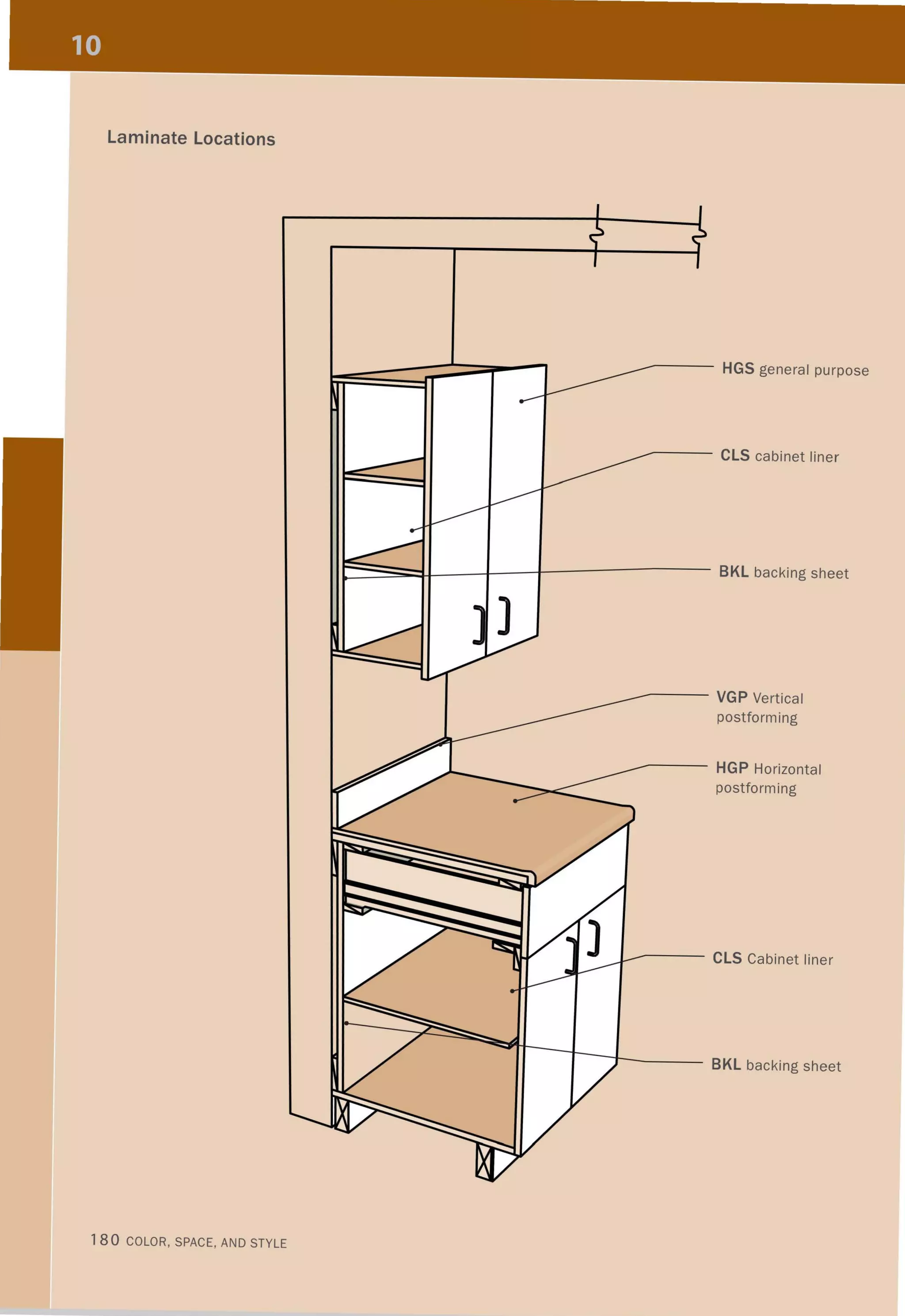
![TERRAZZO FINISHES
Description
Sand-Cushioned
Bonded
Monolithic
Thinset
~ - -- ---- ~
Sand-Cushioned
•
"<l ' . .II
..
•
•
"
•
"..
•
•
•
Monolithic
•
•
"•
•
•
•
•
•
"
Thickness
3" (76) (including
'/2" (13) terrazzo
topping)
1 3/4"-2 '/4" (45-57)
(including '/2" (13)
terrazzo topping)
'/2" (13)
'/4" (6) or 3/8" (9.5)
(#2 chips only for
3/8" [9.5])
------------ --
,., '.
• •
•
• ••
" ~
• ID
r-...• • •
~
• •
"
M
•
"• •• •
•
•
•
Divider Spacing Advantages
4' (1 219) ::; on interior floor use on lower
center levels of structure; separated
from substrate by an isolation
membrane; good for patterns
and colors
6'-8' (1 829-2438) wherever thickness needs to be
on center minimized, but a cementitious
matrix is desired; good for walls
and other vertical surfaces
20' x 20' (6096 x set directly on a level concrete
6096) spans and substrate; economical and
all locations of ideal for large areas
concrete substrate
joints
20' x 20' (6096 x set directly on a level concrete
6096) spans and substrate; ideal for multilevel
all locations of installations; wide range of
concrete substrate colors available; resistant to
joints chemical spills
"'."
. ". • ••
Bonded
~
M
~
=N
~ " •• • '"• •
• ~
• • E•
• •" .
" • E
"
~
• g
• • ID• • • r-...
• ~
". "• • • • " .• •
Thinset
Material 165](https://image.slidesharecdn.com/colorspaceandstyle-allthedetails-noithat101-170426124809/75/Color-Space-and-Style-167-2048.jpg)
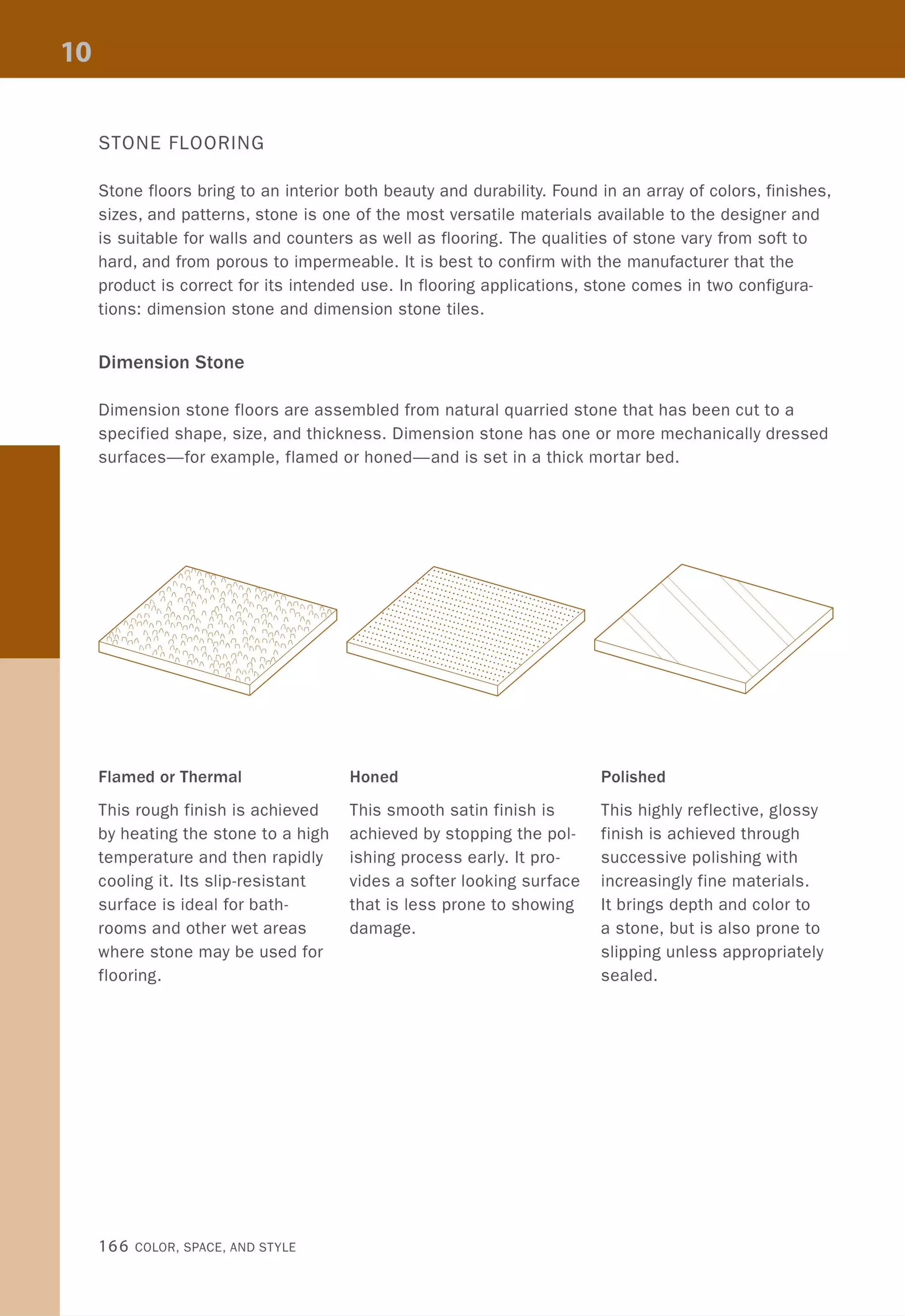


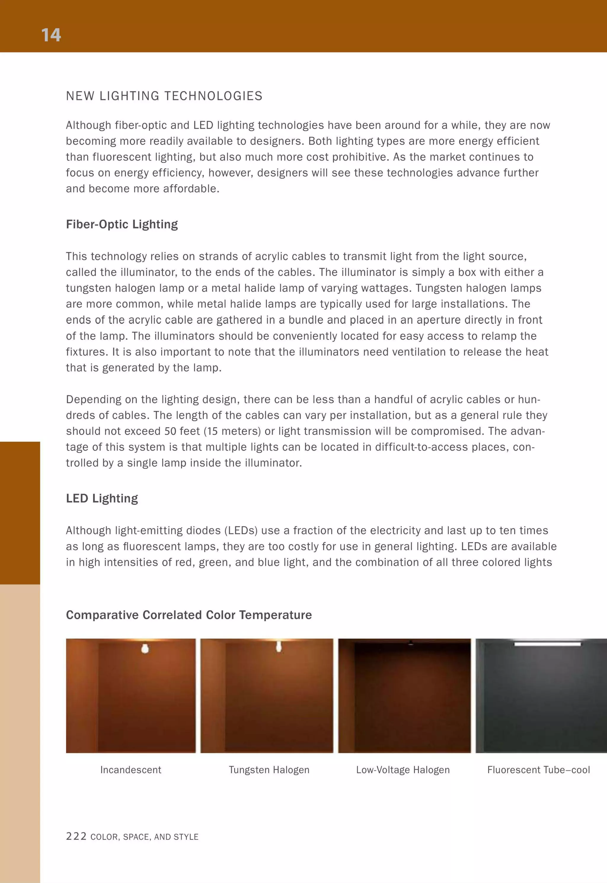
![Incandescent
Tungsten Halogen
Low-Voltage Halogen
~ I Ie
Fluorescent Tube
Compact Fluorescent
Metal Halide
High-Pressure Sodium
2600-3100K
I I I I +
Efficacy: 1 100
Lamp Life: 750-1,000 hours
Ballast/Transformer: no
Start-to-Full Output: instant
IIIII IIIIIII IIIIIIIII IIIIII
3000K
I I
Efficacy: 2
Lamp Life: 2,000-3,000 hours
Ballast/Transformer: no
Start-to-Full Output: instant
95
IIIIIIIIIIIIIIIIIIIII IIIIII
3000K
I I
Efficacy: 2
Lamp Life: 2,000-4,000 hours
Ballast/Transformer: yes
Start-to-Full Output: instant
95
1 1 111 1 11 [] 111111 1 111 1 II I II
3000-6000K
1 1 1 1 + 1
Efficacy: 5
75-85
Lamp Life: 18,000-24,000 hours
Ballast/Transformer: yes
Start-to-Full Output: nearly instant
1111111 1 1 111 1 11 1 11 1 11 IUIII
3000-5000K
1 1 1 1 1 1 1 1 + 1 1
Efficacy: 5 75-85
Lamp Life: 10,000-20,000 hours
Ballast/Transformer: yes
Start-to-Full Output: nearly instant
111 1 111 1 11111 1 11111 1 1 11 I 11
6000K
+ I I
Efficacy: 5
65
Lamp Life: 10,000-20,000 hours
Ballast/Transformer: yes
Start-to-Full Output: 5-10 minutes
_I 'll 11 11 1 1 11 11 11111 I 1 11 11 1
2100K
I I +
Efficacy: 5
65
Lamp Life: 24,000 hours
Ballast/Transformer: yes
Start-to-Full Output: 3-5 minutes
Artificial Light 221](https://image.slidesharecdn.com/colorspaceandstyle-allthedetails-noithat101-170426124809/75/Color-Space-and-Style-223-2048.jpg)


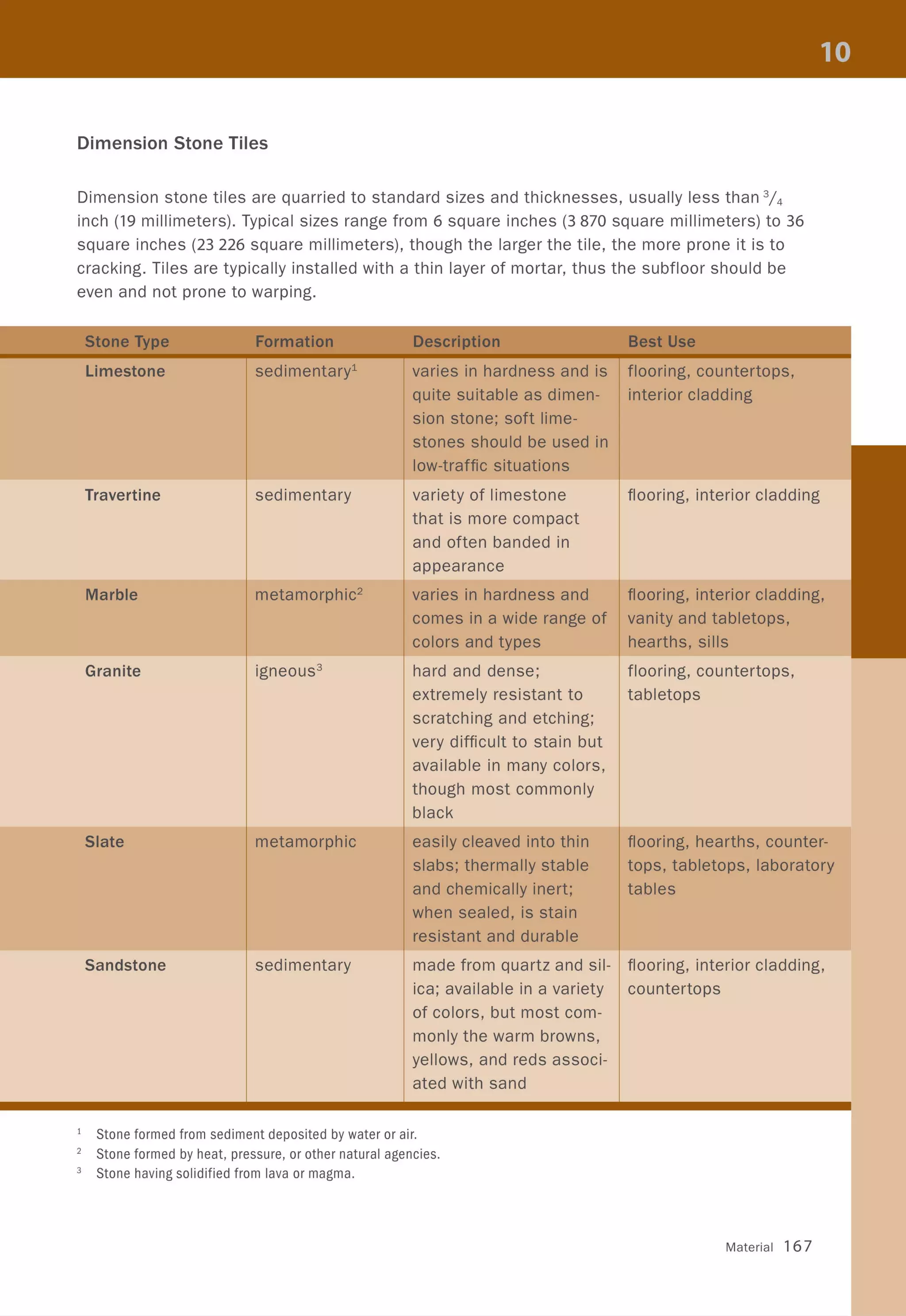
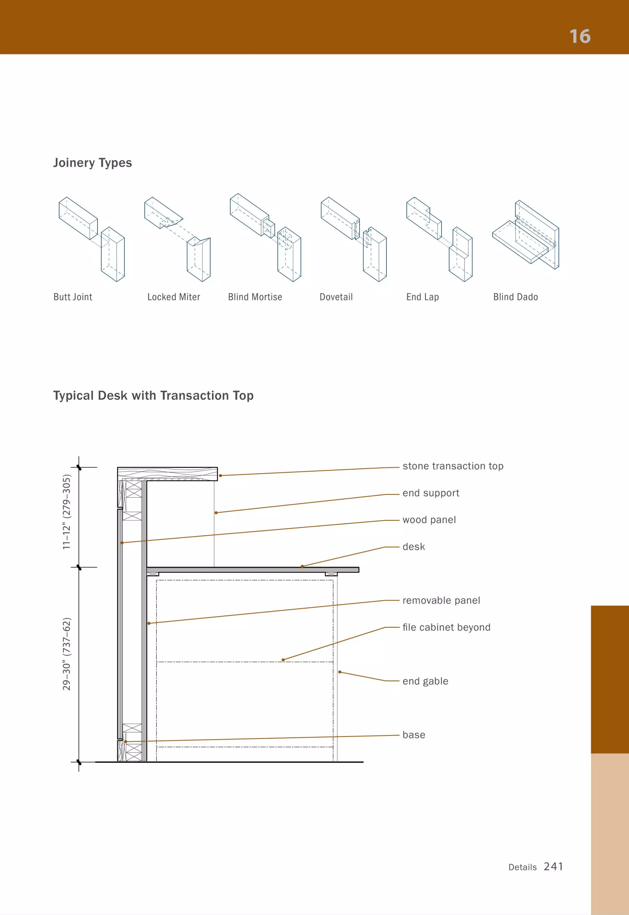
![Partitions over Existing Walls
Direct to Structure
Furring channel @ 16" (400).
1 layer Sfs" (16) GWB.
Corner Conditions
IX~
Inside Corner with Reveal
One Side
Base Conditions
><
Low- and High-Profile
Reveals
u
o
D°
o
DO
n
1------,1
I
I
I
I
Structure with Mechanical
1 layer Sfs" (16) GWB one side
of 2" x 4" (38 x 99) studs @ 16"
(400) ~C . Tie back to wall with
metal clips.
Typical Outside Corner
Recessed
Poured Base
Recessed
Wood Base
Corner Bead
]
J-Mold
J
Shadowline J-Mold
Control Joint
u
Reveal Mold
Direct
Applied
Vinyl
><
Direct
Applied
Wood
239](https://image.slidesharecdn.com/colorspaceandstyle-allthedetails-noithat101-170426124809/75/Color-Space-and-Style-241-2048.jpg)


![[BROCHURE] Italy Tour Project | @SlideON](https://cdn.slidesharecdn.com/ss_thumbnails/brochure8-251215152319-2805af68-thumbnail.jpg?width=640&height=640&fit=bounds)


