Download to read offline
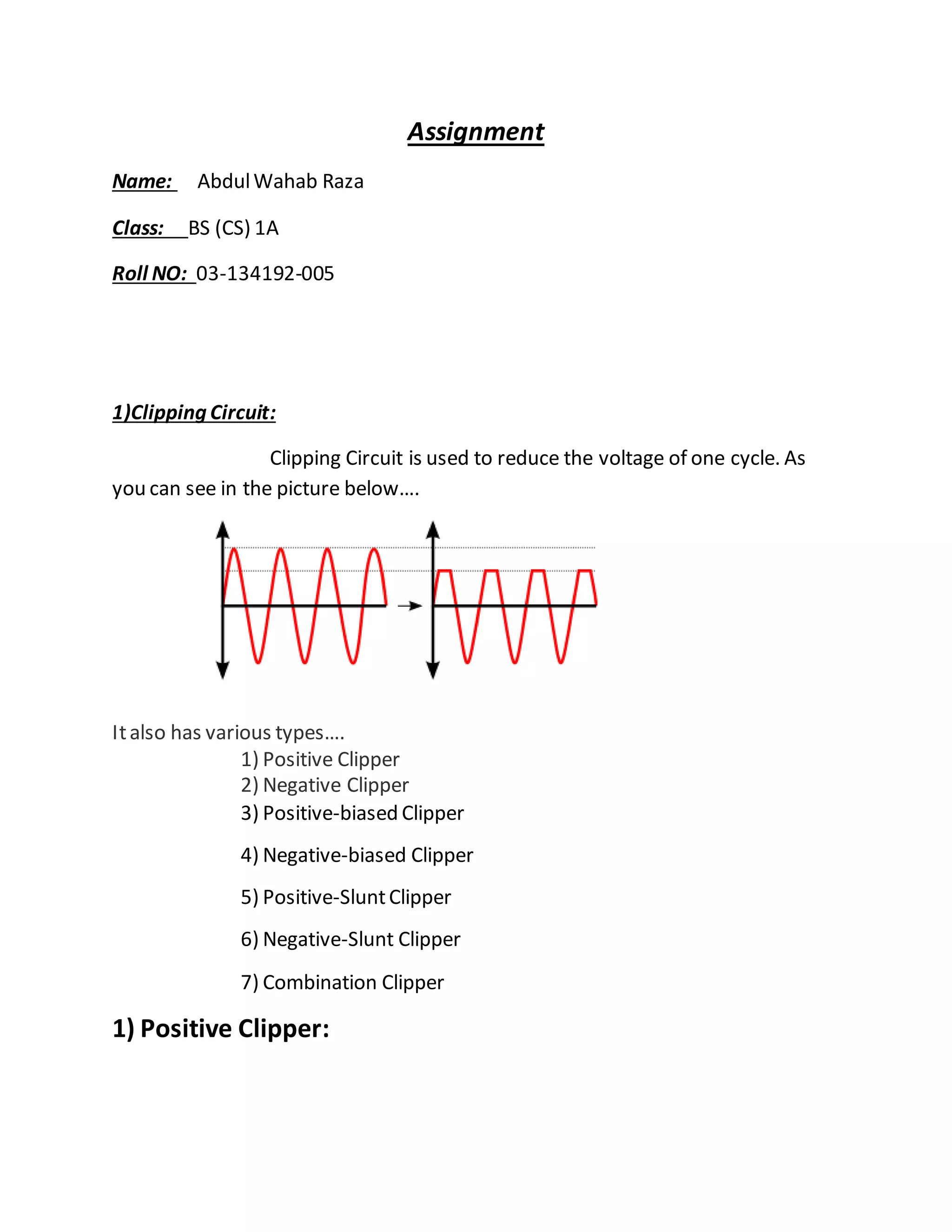
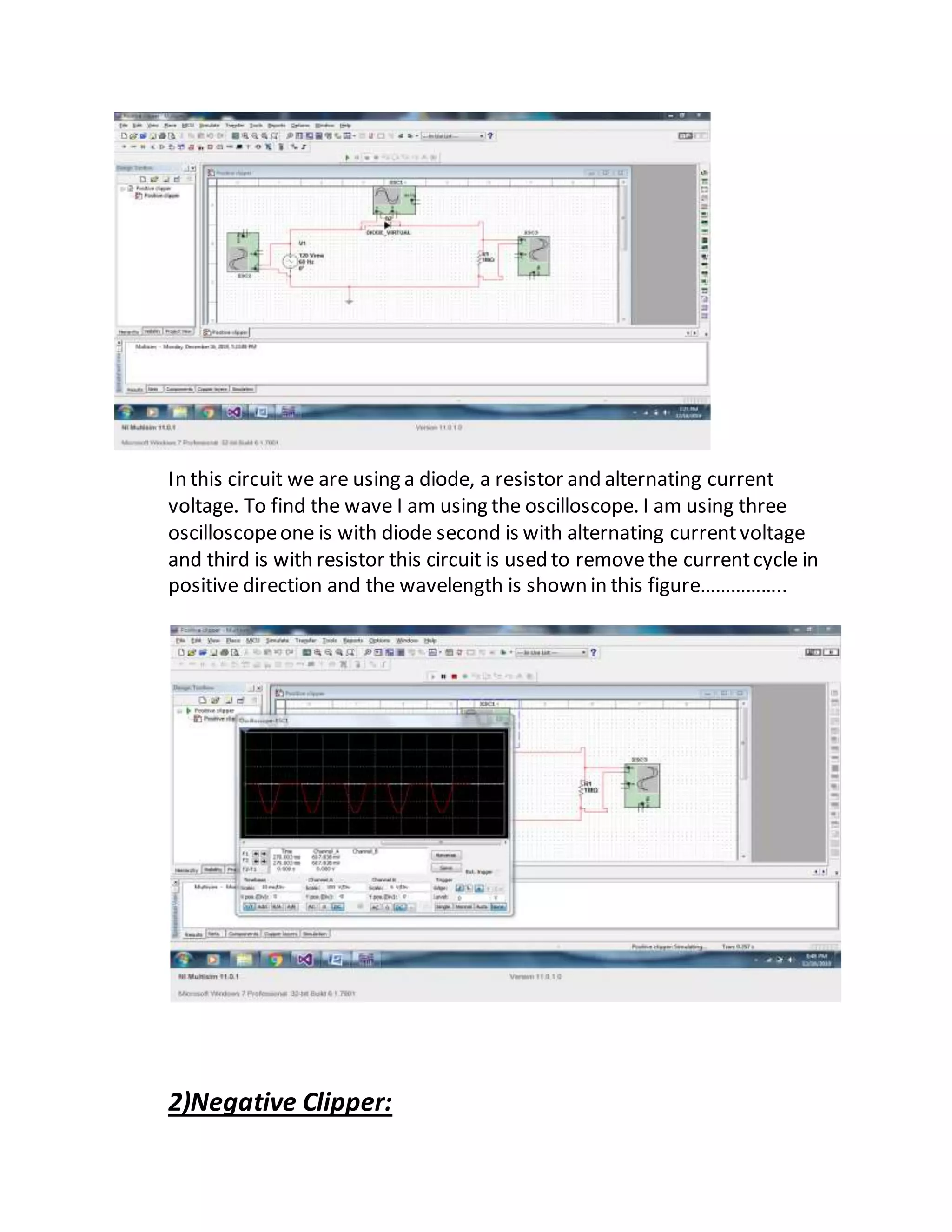
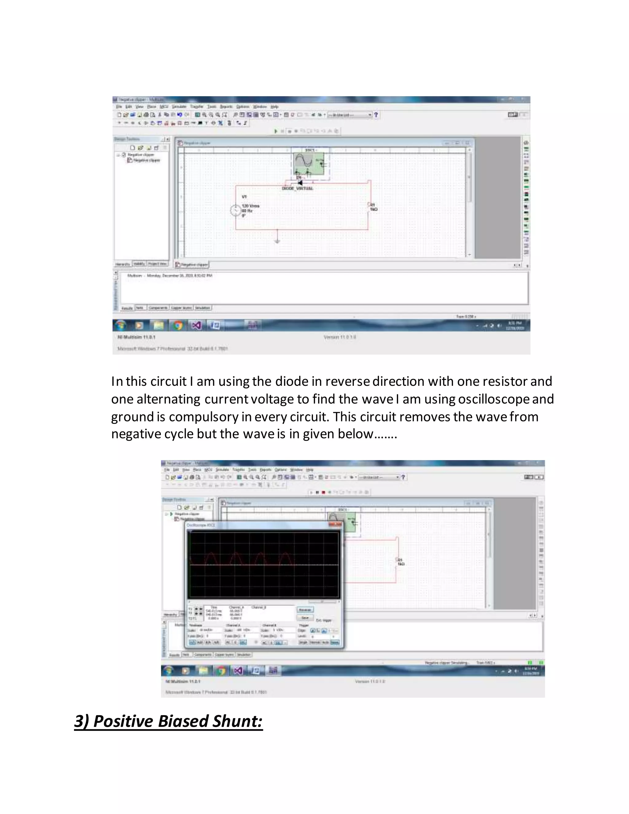
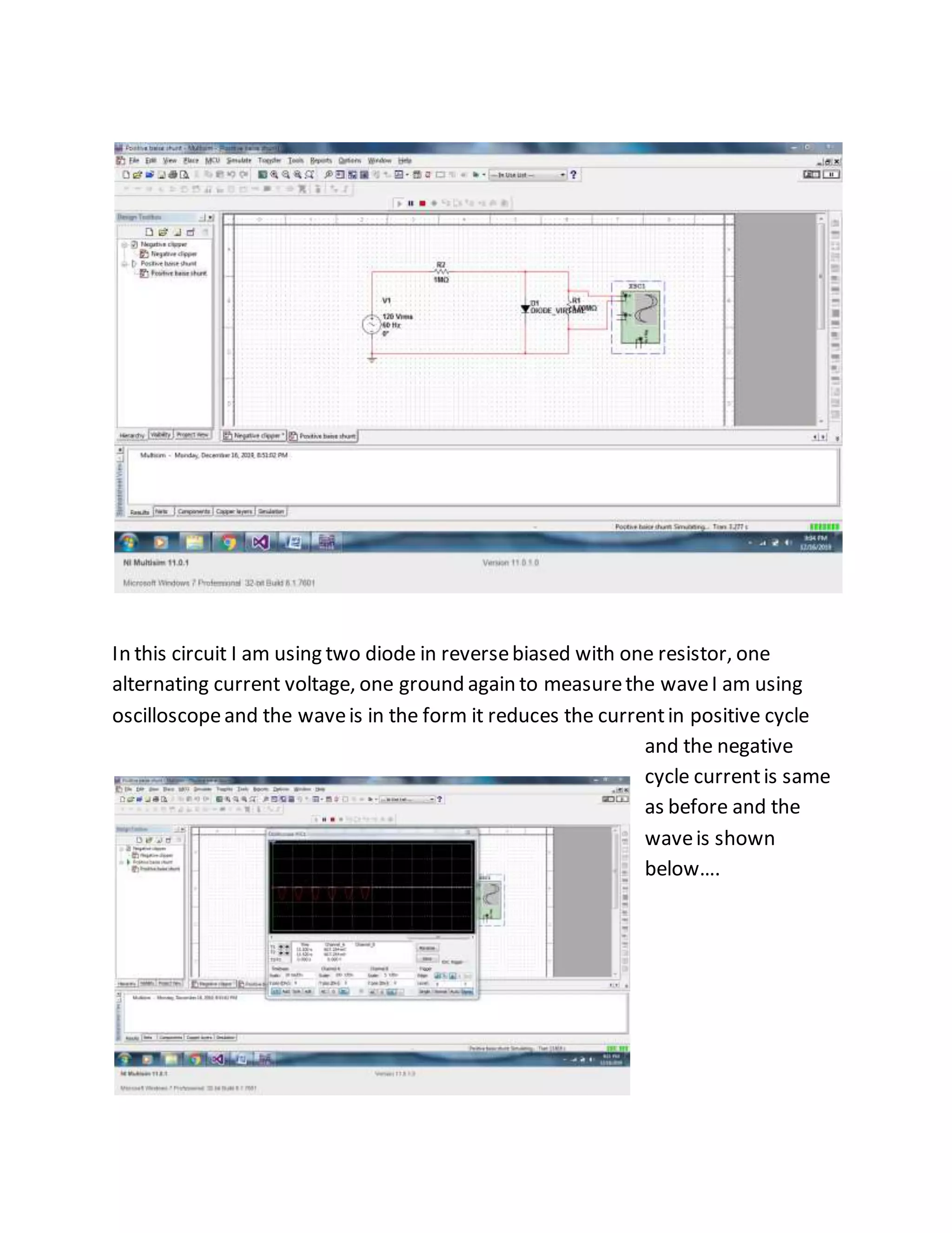
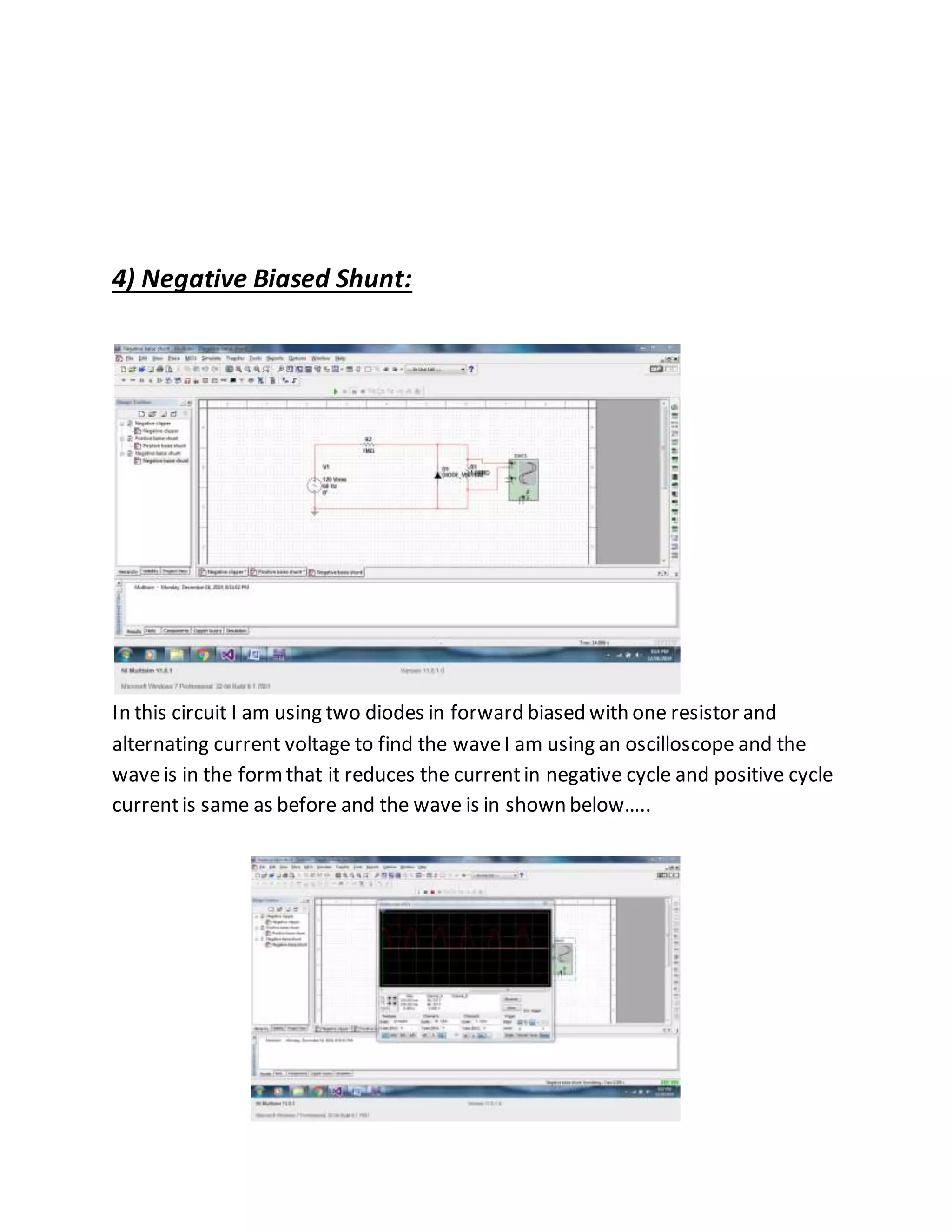
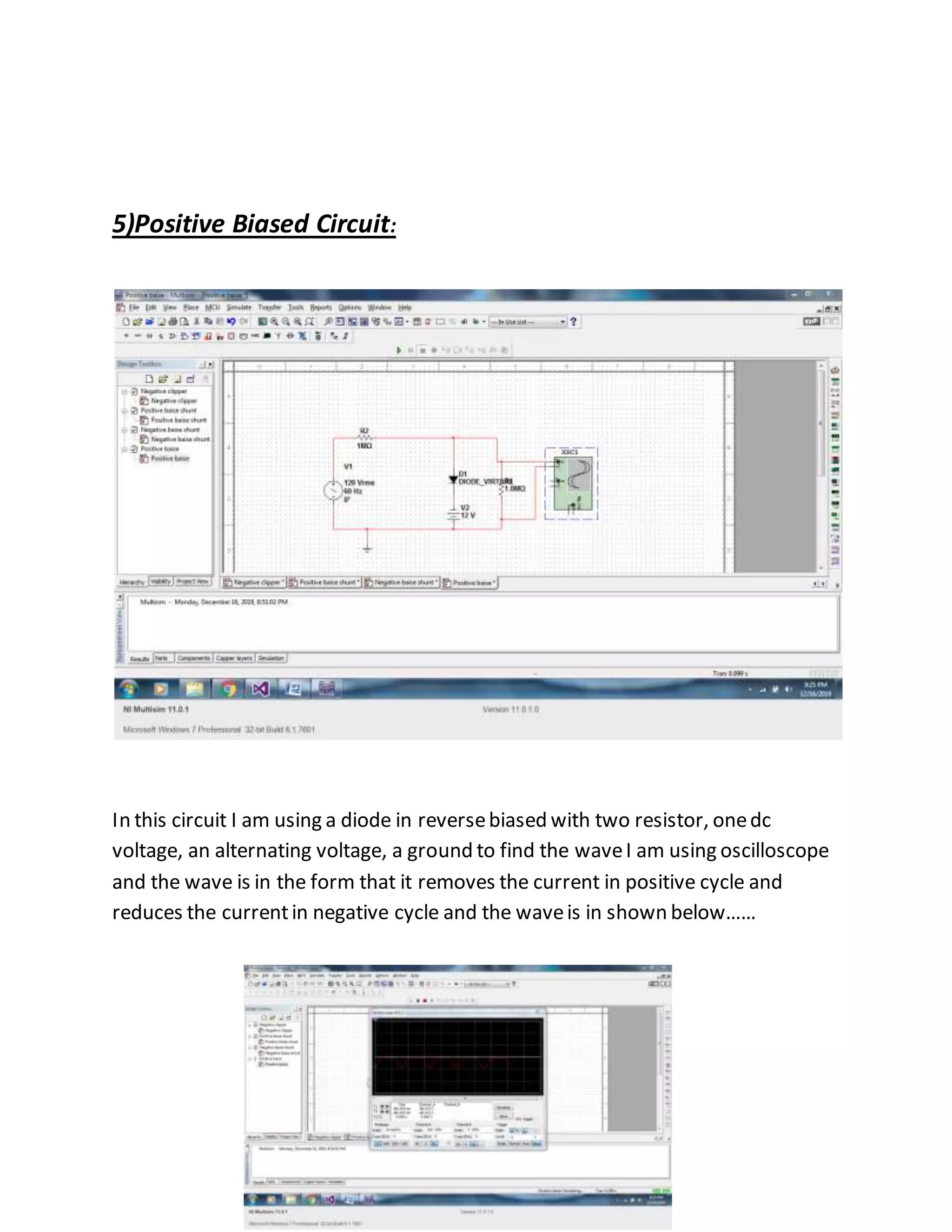
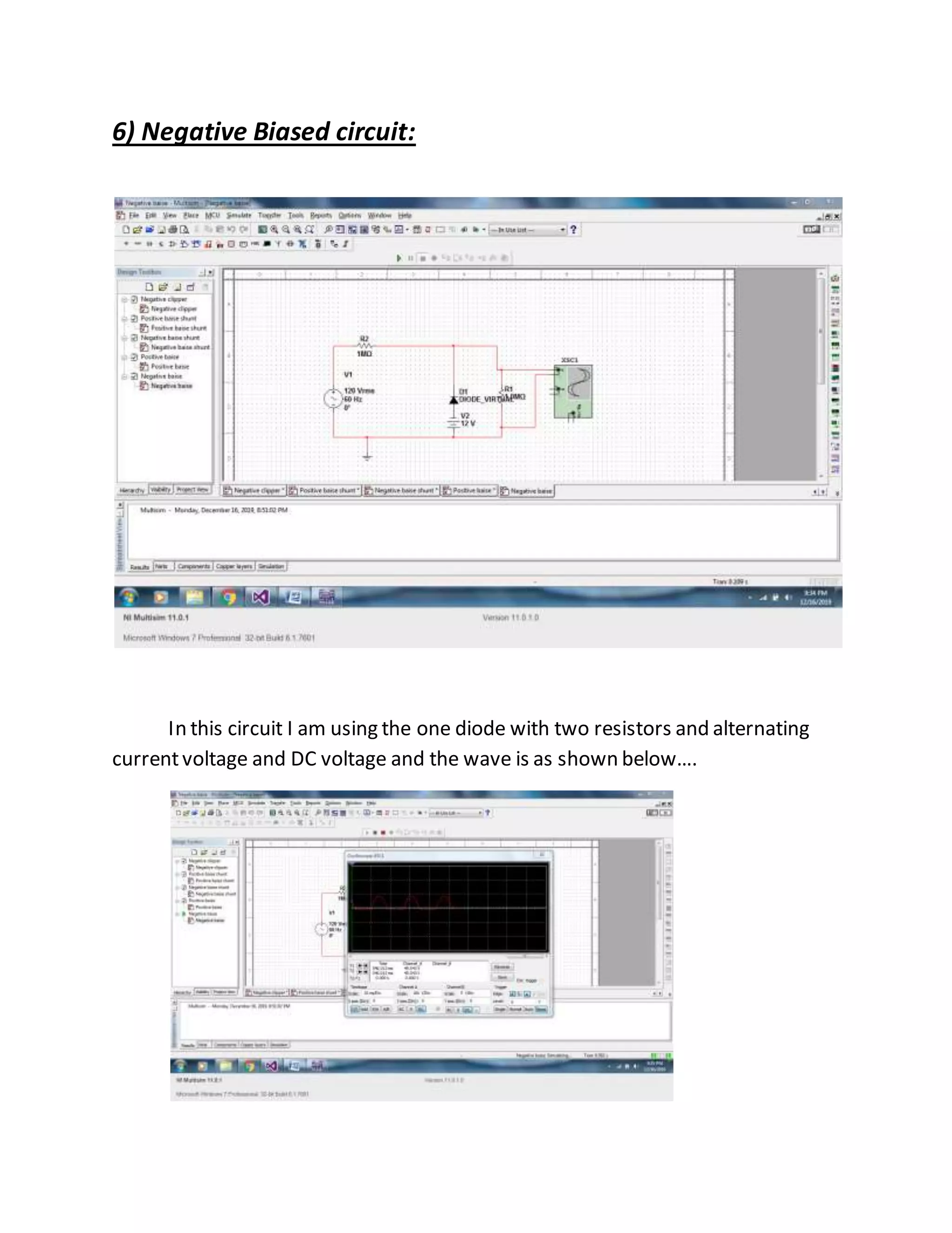

This document describes different types of clipping circuits that AbdulWahab Raza experimented with for his class assignment. It discusses positive, negative, positive-biased, and negative-biased clipper circuits. For each circuit, it explains the circuit components used and describes the resulting waveform observed on an oscilloscope. The circuits are designed to reduce or remove portions of an alternating current waveform in either the positive or negative cycle.


