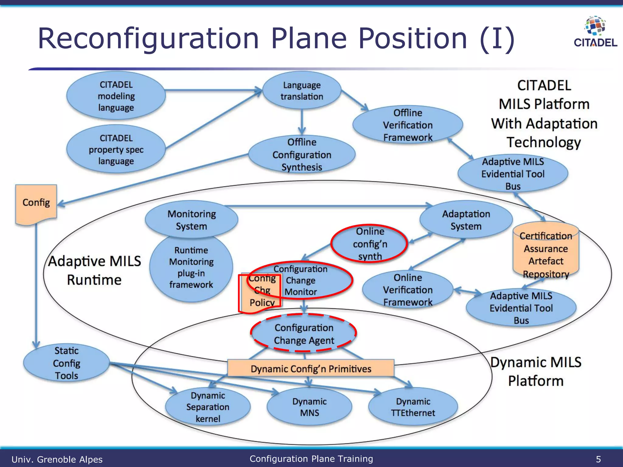
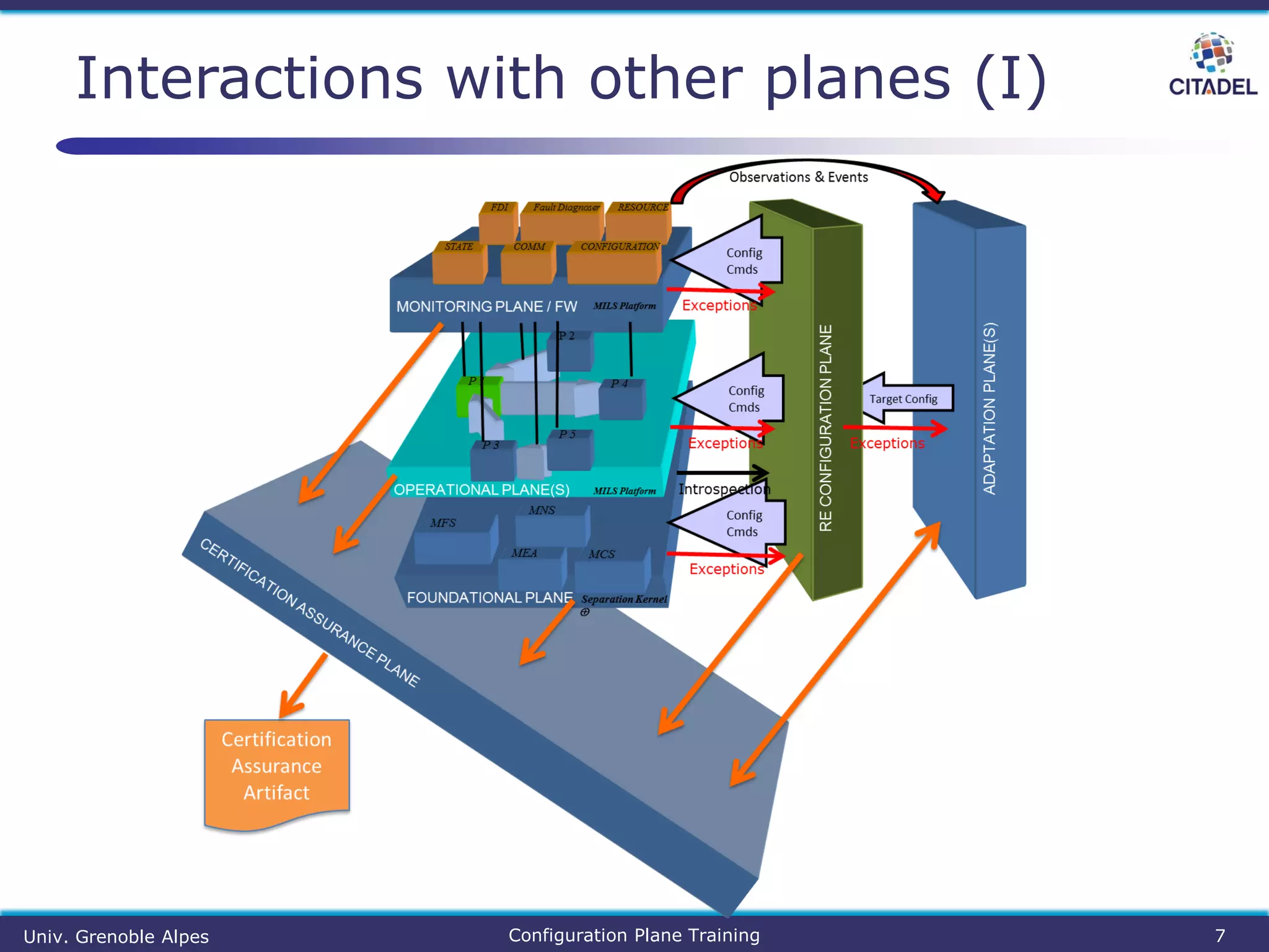
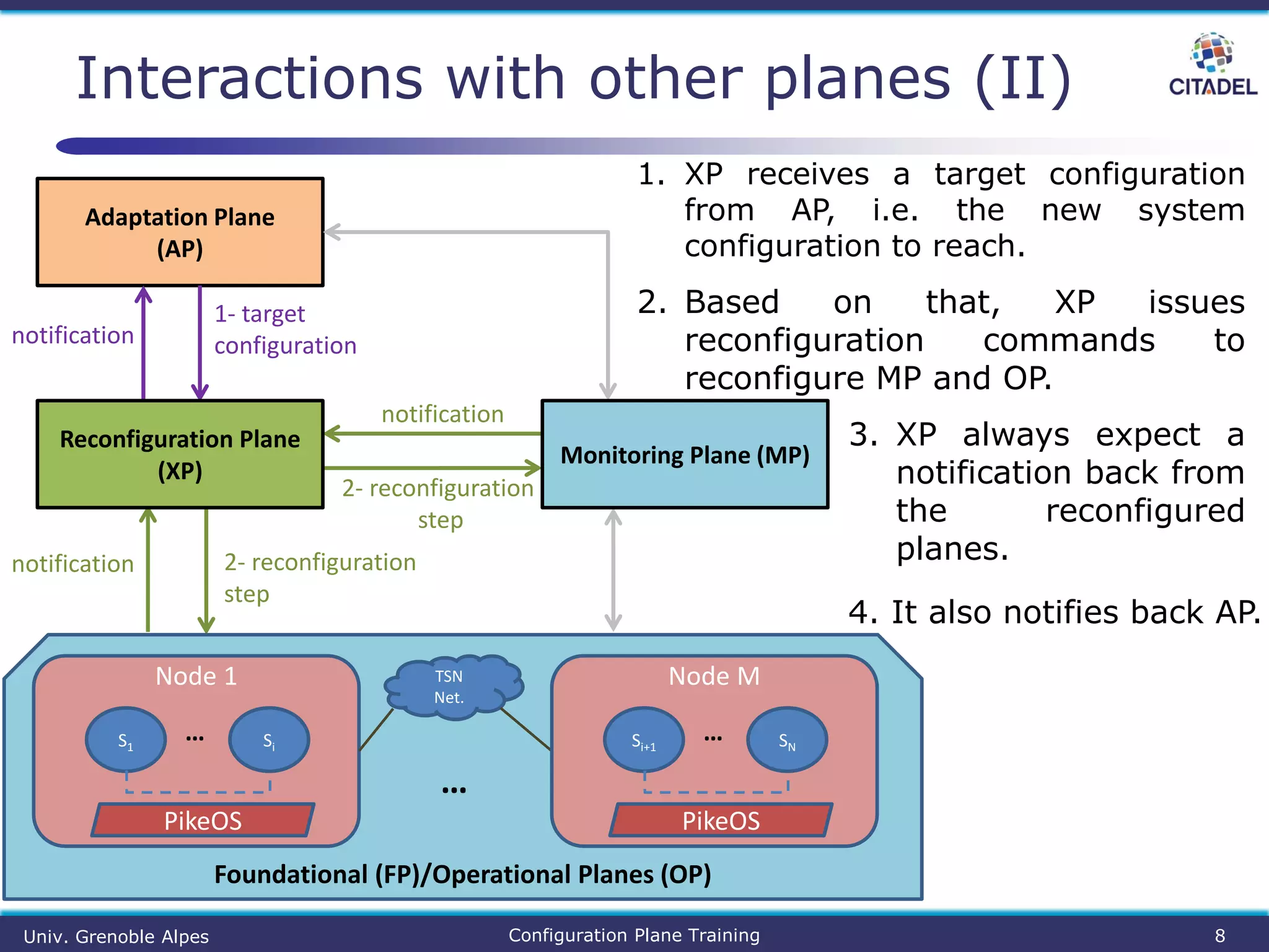
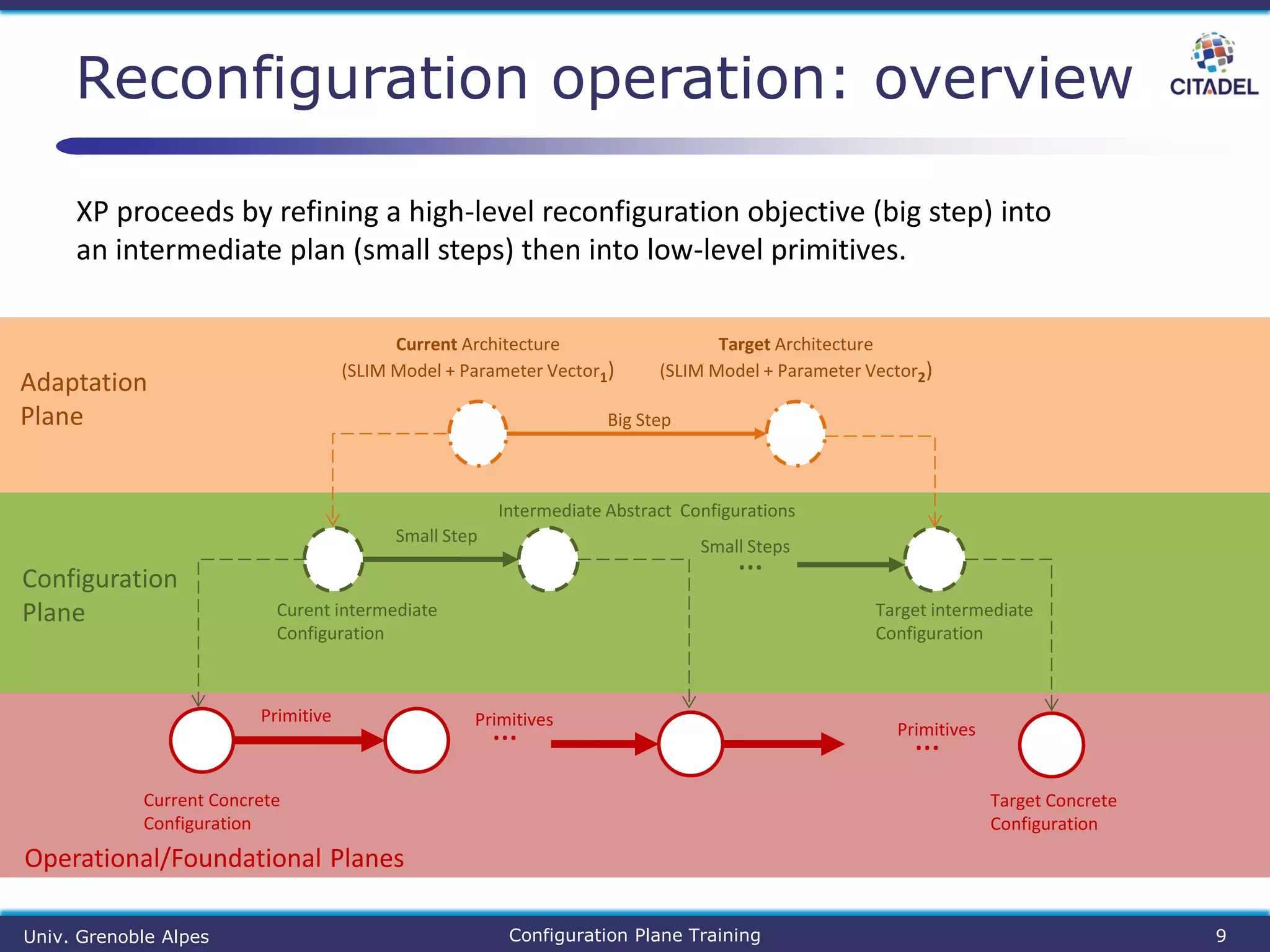
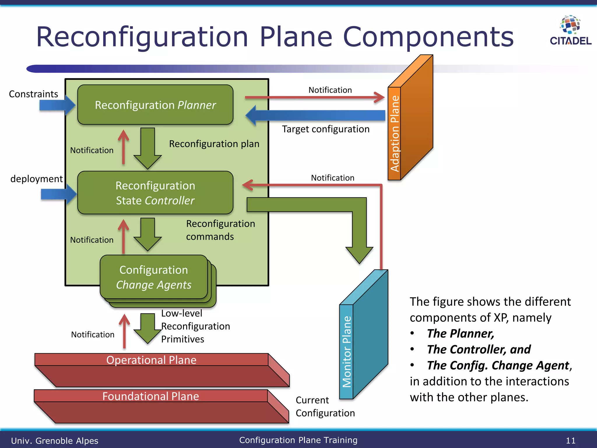
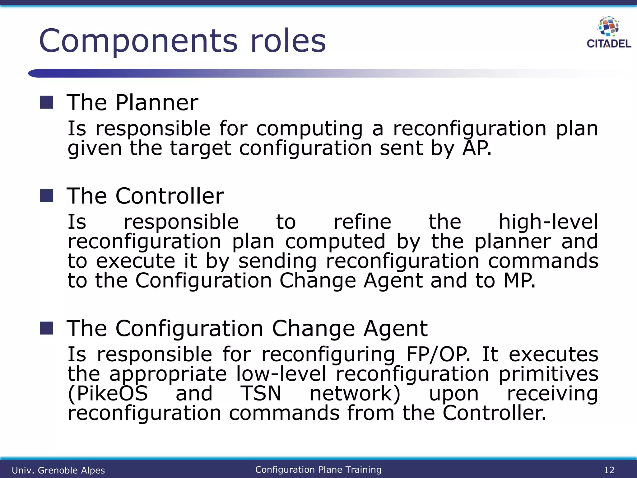
The document details the Citadel configuration plane, outlining its role in reconfiguring the adaptive Mils system through high-level design to low-level implementation on the Citadel platform. It provides training materials intended for system integrators, including the implementation components, interactions with other planes, and the reconfiguration process. A practical example illustrates the steps involved in reconfiguring a sender and receiver on the platform.
![ Back-end usage
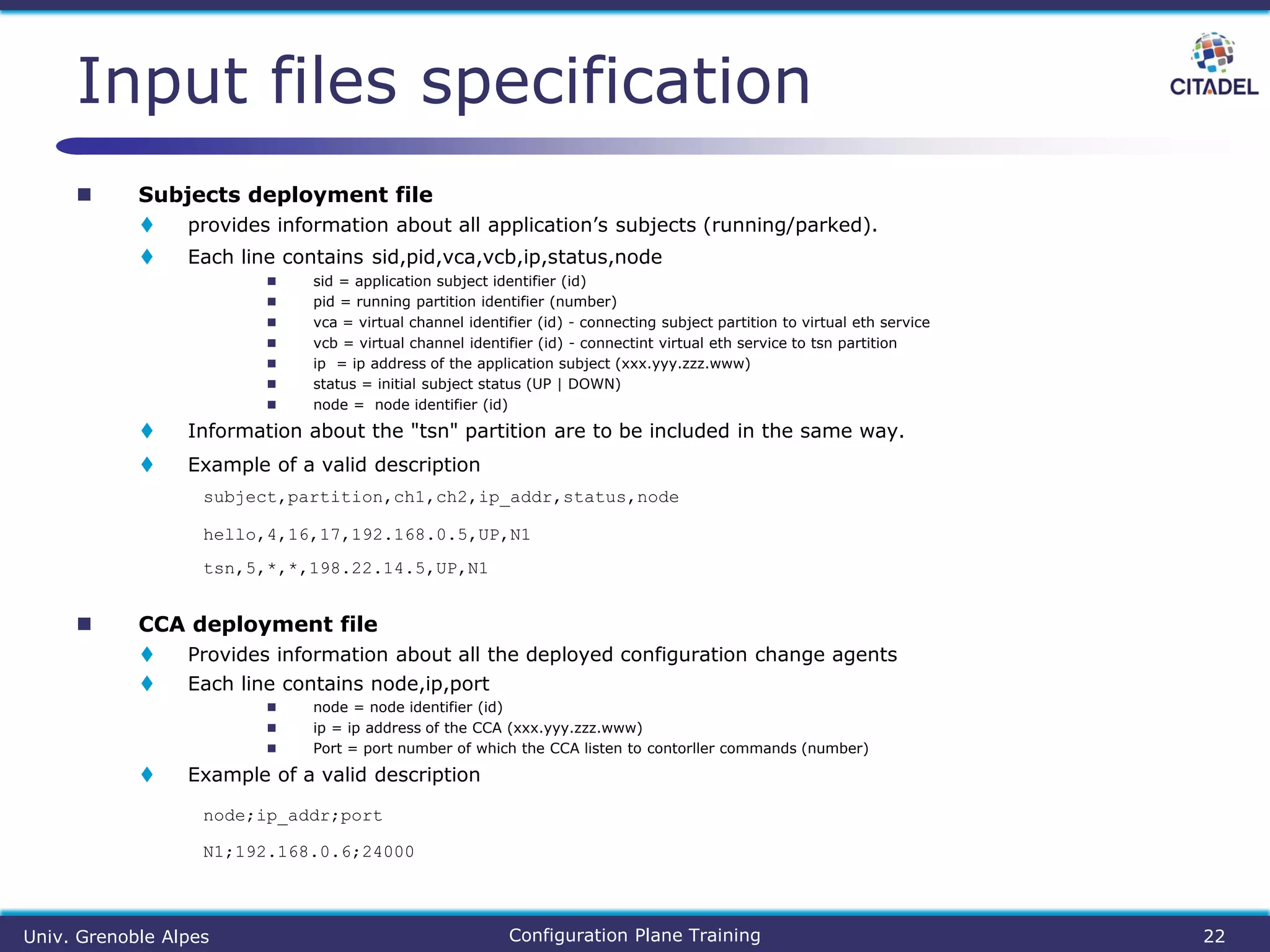
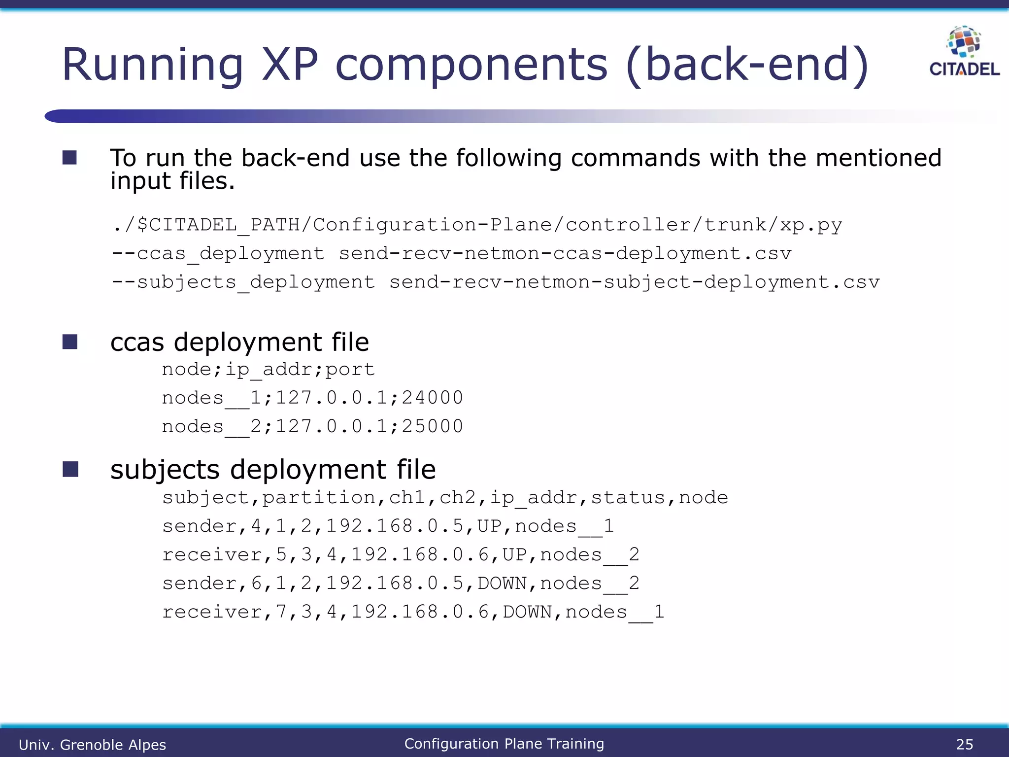
./xp.py --ccas_deployment <CCAS deployment file>
--subjects_deployment <subjects deployment file>
Requirements
● Python 2.7
● NetworkX Python library
● CITADEL Framework
● Compass tool
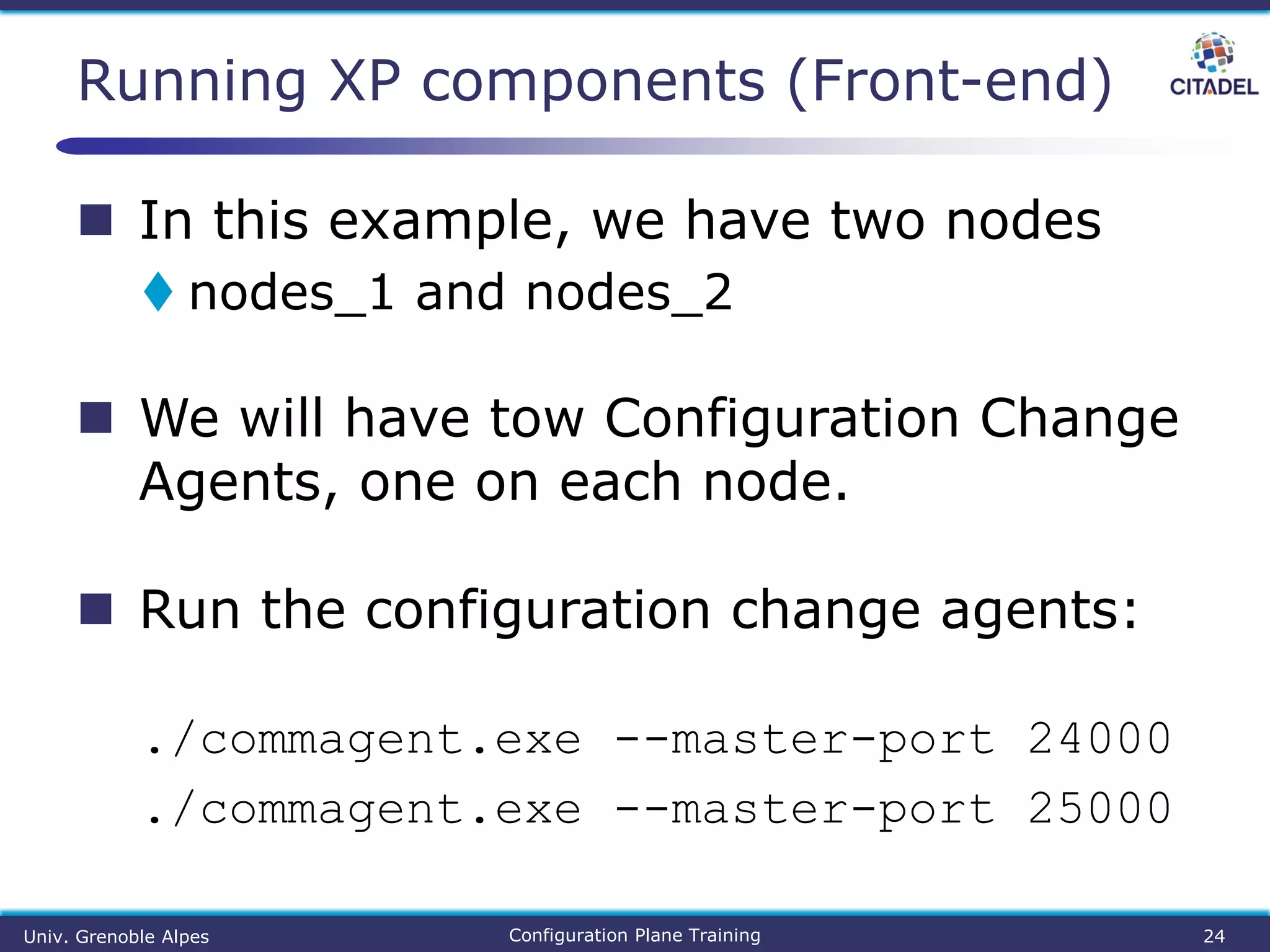
Front-end usage
Communication agent
Commagent [--master-port=PORT] [--interceptor-
port=PORT]
Core agent
● Automatically started (PikeOS process)
Usage
Univ. Grenoble Alpes Configuration Plane Training 21](https://image.slidesharecdn.com/citadel-config-reconfig-synthesis-training-191121115509/75/CITADEL-configuration-and-reconfiguration-synthesis-21-2048.jpg)


![[Capella Day 2019] Model execution and system simulation in Capella](https://cdn.slidesharecdn.com/ss_thumbnails/modelexecutionandsystemsimulationincapellav1-191001130117-thumbnail.jpg?width=640&height=640&fit=bounds)


