Cisco labs practical7
•
1 like•461 views

This document provides instructions for configuring VLAN trunking between two switches using the VLAN Trunking Protocol (VTP). The objectives are to create VLANs on a VTP server switch, configure one switch as the VTP server and the other as the client, establish an 802.1q trunk between the switches, and test connectivity across VLANs when moving a workstation between ports on different VLANs.

More Related Content
What's hot
What's hot (19)
Viewers also liked
Viewers also liked (20)
Similar to Cisco labs practical7
Similar to Cisco labs practical7 (20)
Cisco labs practical7
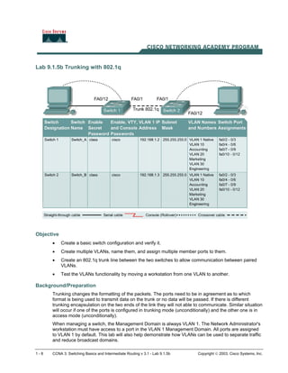
- 1. Lab 9.1.5b Trunking with 802.1q Objective • Create a basic switch configuration and verify it. • Create multiple VLANs, name them, and assign multiple member ports to them. • Create an 802.1q trunk line between the two switches to allow communication between paired VLANs. • Test the VLANs functionality by moving a workstation from one VLAN to another. Background/Preparation Trunking changes the formatting of the packets. The ports need to be in agreement as to which format is being used to transmit data on the trunk or no data will be passed. If there is different trunking encapsulation on the two ends of the link they will not able to communicate. Similar situation will occur if one of the ports is configured in trunking mode (unconditionally) and the other one is in access mode (unconditionally). When managing a switch, the Management Domain is always VLAN 1. The Network Administrator's workstation must have access to a port in the VLAN 1 Management Domain. All ports are assigned to VLAN 1 by default. This lab will also help demonstrate how VLANs can be used to separate traffic and reduce broadcast domains. 1 - 8 CCNA 3: Switching Basics and Intermediate Routing v 3.1 - Lab 9.1.5b Copyright 2003, Cisco Systems, Inc.
- 2. Cable a network similar to one of the diagram. The configuration output used in this lab is produced from 2950 series switch. Any other switch used may produce different output. The following steps are intended to be executed on each switch unless specifically instructed otherwise. Start a HyperTerminal session. Note: Go to the erase and reload instructions at the end of this lab. Perform those steps on all switches in this lab assignment before continuing. Step 1 Configure the switch Configure the Hostname, access and command mode passwords, as well as the management LAN settings. These values are shown in the chart. If problems occur while performing this configuration, refer to the “Basic Switch Configuration lab”. Do not configure VLANs and trunking yet. Step 2 Configure the hosts attached to the switch Configure the IP address, mask, and default gateway on each host. Be sure to choose addresses that are on the same subnet as the switch. Step 3 Verify connectivity a. To verify that the host and switch are correctly configured, ping the switch from the hosts. b. Were the pings successful? __________________________________________________ c. If the answer is no, troubleshoot the host and switches configurations. Step 4 Display the VLAN interface information On Switch_A, type the command show vlan at the Privileged EXEC prompt as follows: Switch_A#show vlan Note: There should be an entry for VLAN 1 and the default VLANs (1002 +). If other VLANs appear, they could be deleted as instructed in Step 2 of the Erasing and Reloading instructions at the end of this lab or refer to the Lab Exercise: Deleting VLAN Configurations. Step 5 Create and name three VLANs Enter the following commands to create and name three VLANs: Switch_A#vlan database Switch_A(vlan)#vlan 10 name Accounting Switch_A(vlan)#vlan 20 name Marketing Switch_A(vlan)#vlan 30 name Engineering Switch_A(vlan)#exit Use the show vlan command to verify that the VLANs have been created correctly. Step 6 Assign ports to a VLAN 10 Assigning ports to VLANs must be done from the interface mode. Enter the following commands to add ports 0/4 to 0/6 to VLAN 10: Switch_A#configure terminal Switch_A(config)#interface fastethernet 0/4 Switch_A(config-if)#switchport mode access Switch_A(config-if)#switchport access vlan 10 2 - 8 CCNA 3: Switching Basics and Intermediate Routing v 3.1 - Lab 9.1.5b Copyright 2003, Cisco Systems, Inc.
- 3. Switch_A(config-if)#interface fastethernet 0/5 Switch_A(config-if)#switchport mode access Switch_A(config-if)#switchport access vlan 10 Switch_A(config-if)#interface fastethernet 0/6 Switch_A(config-if)#switchport mode access Switch_A(config-if)#switchport access vlan 10 Switch_A(config-if)#end Step 7 Assign ports to VLAN 20 Enter the following commands to add ports 0/7 to 0/9 to VLAN 20: Switch_A#configure terminal Switch_A(config)#interface fastethernet 0/7 Switch_A(config-if)#switchport mode access Switch_A(config-if)#switchport access vlan 20 Switch_A(config-if)#interface fastethernet 0/8 Switch_A(config-if)#switchport mode access Switch_A(config-if)#switchport access vlan 20 Switch_A(config-if)#interface fastethernet 0/9 Switch_A(config-if)#switchport mode access Switch_A(config-if)#switchport access vlan 20 Switch_A(config-if)#end Step 8 Assign ports to VLAN 30 Enter the following commands to add ports 0/10 to 0/12 to VLAN 30: Switch_A#configure terminal Switch_A(config)#interface fastethernet 0/10 Switch_A(config-if)#switchport mode access Switch_A(config-if)#switchport access vlan 30 Switch_A(config-if)#interface fastethernet 0/11 Switch_A(config-if)#switchport mode access Switch_A(config-if)#switchport access vlan 30 Switch_A(config-if)#interface fastethernet 0/12 Switch_A(config-if)#switchport mode access Switch_A(config-if)#switchport access vlan 30 Switch_A(config-if)#end Step 9 Create VLANs on Switch_B Repeat Steps 5 through 9 on Switch_B to create its VLANs Step 10 Display the VLAN interface information a. On both switches, type the command show vlan at the Privileged EXEC prompt as follows: Switch_A#show vlan b. Are ports 0/10 through 0/12 assigned to VLAN 30? __________________________________________________________________________ 3 - 8 CCNA 3: Switching Basics and Intermediate Routing v 3.1 - Lab 9.1.5b Copyright 2003, Cisco Systems, Inc.
- 4. Step 11 Test the VLANs Ping from the host in Switch_A port 0/12 to the host in Switch_B port 0/12. a. Was the ping successful? ___________________________________________________ b. Why? __________________________________________________________________ Ping from the host in Switch_A port 0/12 to the switch IP 192.168.1.2. c. Was the ping successful? ___________________________________________________ d. Why? __________________________________________________________________ Step 12 Create the trunk On both switches, Switch_A and Switch_B, type the following command at the fastethernet 0/1 interface command prompt. Note that it is not necessary to specify the encapsulation on a 2950, since it only supports 802.1Q. Switch_A(config)#interface fastethernet 0/1 Switch_A(config-if)#switchport mode trunk Switch_A(config-if)#end Switch_B(config)#interface fastethernet 0/1 Switch_B(config-if)#switchport mode trunk Switch_B(config-if)#end 2900: Switch_A(config)#interface fastethernet0/1 Switch_A(config-if)#switchport mode trunk Switch_A(config-if)#switchport trunk encapsulation dot1q Switch_A(config-if)#end Switch_B(config)#interface fastethernet0/1 Switch_B(config-if)#switchport mode trunk Switch_B(config-if)#switchport trunk encapsulation dot1q Switch_B(config-if)#end Step 13 Verify the trunk a. To verify that port Fast Ethernet 0/1 has been established as a trunk port, type show interface fastethernet 0/1 switchport at the Privileged EXEC mode prompt. b. What type of trunking encapsulation is shown on the output results? __________________________________________________________________________ c. According to the output with show interface fastethernet 0/1 switchport on Switch_B, is there a difference from the Administrative Trunking Encapsulation from the Operational Trunking Encapsulation? __________________________________________________________________________ d. On the fragment “Trunking VLANs Enable” from the output, what does the word “ALL” mean? __________________________________________________________________________ e. What would happen if the two ports of the trunk were using different encapsulation? _________ f. Explain _________________________________________________________________ 4 - 8 CCNA 3: Switching Basics and Intermediate Routing v 3.1 - Lab 9.1.5b Copyright 2003, Cisco Systems, Inc.
- 5. Step 14 Test the VLANS and the trunk Ping from the host in Switch_A port 0/12 to the host in Switch_B port 0/12. a. Was the ping successful? ___________________________________________________ b. Why? __________________________________________________________________ Ping from the host in Switch_A port 0/12 to the switch IP 192.168.1.2. c. Was the ping successful? ___________________________________________________ d. Why? __________________________________________________________________ Step 15 Move host. Move the host in Switch_A from port 0/12 to port 0/8. Wait until the port LED goes green and then go to the next step. Step 16 Test the VLANS and the trunk Ping from the host in Switch_A port 0/8 to the host in Switch_B port 0/12. a. Was the ping successful? ___________________________________________________ b. Why? __________________________________________________________________ Ping from the host in Switch_A port 0/8 to the switch IP 192.168.1.2. c. Was the ping successful? ___________________________________________________ d. Why? __________________________________________________________________ Step 17 Move host Move the host in Switch_B from port 0/12 to port 0/7. Wait until the port LED goes green and then go to the next step. Step 18 Test the VLANS and the trunk Ping from the host in Switch_A port 0/8 to the host in Switch_B port 0/7. a. Was the ping successful? ___________________________________________________ b. Why? __________________________________________________________________ Ping from the host in Switch_A port 0/8 to the switch IP 192.168.1.2. c. Was the ping successful? ___________________________________________________ d. Why? __________________________________________________________________ Step 19 Move hosts Move the host in Switch_A from port 0/8 to port 0/2. Wait until the port LED goes green and then go to the next step. Step 20 Test the VLANS and the trunk Ping from the host in Switch_A port 0/2 to the host in Switch_B port 0/7. a. Was the ping successful? ___________________________________________________ Ping from the host in Switch_A port 0/2 to the switch IP 192.168.1.2. 5 - 8 CCNA 3: Switching Basics and Intermediate Routing v 3.1 - Lab 9.1.5b Copyright 2003, Cisco Systems, Inc.
- 6. b. Was the ping successful? ___________________________________________________ c. Why? __________________________________________________________________ Step 21 Move host Move the host in Switch_B from port 0/7 to port 0/3. Wait until the port LED goes green and then go to the next step. Step 22 Test the VLANS and the trunk Ping from the host in Switch_A port 0/2 to the host in Switch_B port 0/3. a. Was the ping successful? ___________________________________________________ b. Why? __________________________________________________________________ Ping from the host in Switch_B port 0/3 to the switch IP 192.168.1.2. c. Was the ping successful? ___________________________________________________ d. Why? __________________________________________________________________ Ping from the host in Switch_B port 0/3 to the switch IP 192.168.1.3. e. Was the ping successful? ___________________________________________________ f. Why? __________________________________________________________________ g. What conclusions can be drawn from the testing that was just performed in regards to VLAN membership and VLANs across a trunk? __________________________________________________________________________ __________________________________________________________________________ __________________________________________________________________________ Once the steps are complete, logoff by typing exit, and turn all the devices off. Then remove and store the cables and adapter. 6 - 8 CCNA 3: Switching Basics and Intermediate Routing v 3.1 - Lab 9.1.5b Copyright 2003, Cisco Systems, Inc.
- 7. Erasing and Reloading the Switch For the majority of the labs in CCNA 3 and CCNA 4 it is necessary to start with an unconfigured switch. Use of a switch with an existing configuration may produce unpredictable results. These instructions allow preparation of the switch prior to performing the lab so previous configuration options do not interfere. The following is the procedure for clearing out previous configurations and starting with an unconfigured switch. Instructions are provided for the 2900, 2950, and 1900 Series switches. 2900 and 2950 Series Switches 1. Enter into the Privileged EXEC mode by typing enable. Switch>enable If prompted for a password, enter class, if that does not work, ask the instructor. 2. Remove the VLAN database information file. Switch#delete flash:vlan.dat Delete filename [vlan.dat]?[Enter] Delete flash:vlan.dat? [confirm] [Enter] If there was no VLAN file, this message is displayed. %Error deleting flash:vlan.dat (No such file or directory) 3. Remove the switch startup configuration file from NVRAM. Switch#erase startup-config The responding line prompt will be: Erasing the nvram filesystem will remove all files! Continue? [confirm] Press Enter to confirm. The response should be: Erase of nvram: complete 4. Check that VLAN information was deleted. Verify that the VLAN configuration was deleted in Step 2 using the show vlan command. If previous VLAN configuration information (other than the default management VLAN 1) is still present it will be necessary to power cycle the switch (hardware restart) instead of issuing the reload command. To power cycle the switch, remove the power cord from the back of the switch or unplug it. Then plug it back in. If the VLAN information was successfully deleted in Step 2, go to Step 5 and restart the switch using the reload command. 5. Software restart (using the reload command) 7 - 8 CCNA 3: Switching Basics and Intermediate Routing v 3.1 - Lab 9.1.5b Copyright 2003, Cisco Systems, Inc.
- 8. Note: This step is not necessary if the switch was restarted using the power cycle method. a. At the Privileged EXEC mode enter the command reload. Switch(config)#reload The responding line prompt will be: System configuration has been modified. Save? [yes/no]: b. Type n and then press Enter. The responding line prompt will be: Proceed with reload? [confirm] [Enter] The first line of the response will be: Reload requested by console. After the switch has reloaded, the line prompt will be: Would you like to enter the initial configuration dialog? [yes/no]: c. Type n and then press Enter. The responding line prompt will be: Press RETURN to get started! [Enter] 1900 Series Switches 1. Remove VLAN Trunking Protocol (VTP) information. #delete vtp This command resets the switch with VTP parameters set to factory defaults. All other parameters will be unchanged. Reset system with VTP parameters set to factory defaults, [Y]es or [N]o? Enter y and press Enter. 2. Remove the switch startup configuration from NVRAM. #delete nvram This command resets the switch with factory defaults. All system parameters will revert to their default factory settings. All static and dynamic addresses will be removed. Reset system with factory defaults, [Y]es or [N]o? Enter y and press Enter. 8 - 8 CCNA 3: Switching Basics and Intermediate Routing v 3.1 - Lab 9.1.5b Copyright 2003, Cisco Systems, Inc.
- 9. 1 - 8 CCNA 3: Switching Basics and Intermediate Routing v 3.1 - Lab 9.2.5 Copyright 2003, Cisco Systems, Inc. Lab 9.2.5 VTP Client and Server Configurations Objective • Create a basic switch configuration and verify it. • Create multiple VLANs, name them and assign multiple member ports to them. • Configure the VTP protocol to establish Server and client switches. • Create an 802.1q trunk line between the two switches to allow communication between paired VLANs. • Then test the VLANs functionality by moving a workstation from one VLAN to another. Background/Preparation When managing a switch, the Management Domain is always VLAN 1. The Network Administrator's workstation must have access to a port in the VLAN 1 Management Domain. All ports are assigned to VLAN 1 by default. Cable a network similar to the one of in diagram. The configuration output used in this lab is produced from a 2950 series switch. Any other switch used may produce different output. The following steps are to be executed on each switch unless specifically instructed otherwise. Start a HyperTerminal session.
- 10. 2 - 8 CCNA 3: Switching Basics and Intermediate Routing v 3.1 - Lab 9.2.5 Copyright 2003, Cisco Systems, Inc. Note: Go to the erase and reload instructions at the end of this lab. Perform those steps on all switches in this lab assignment before continuing. Step 1 Configure the switch Configure the hostname, access, and command mode passwords, as well as the management LAN settings. These values are shown in the chart. If problems occur while performing this configuration, refer to the Basic Switch Configuration lab. Step 2 Configure the hosts attached to the switch Configure the IP address, mask, and default gateway on each host. Be sure to choose addresses that are on the same subnet as the switch. Step 3 Verify connectivity a. To verify that the host and switch are correctly configured, ping the switch from the hosts. b. Were the pings successful? __________________________________________________ c. If the answer is no, troubleshoot the host and switches configurations. Step 4 Display the VLAN interface information On Switch_A, type the command show vlan at the Privileged EXEC prompt as follows: Switch_A#show vlan Note: There should be an entry for VLAN 1 and the default VLANs (1002 +). If other VLANs appear, they could be deleted as instructed in Step 2 of the Erasing and Reloading instructions at the end of this lab or refer to the Lab Exercise: Deleting VLAN Configurations. Step 5 Configure VTP a. VLAN Trunking Protocol (VTP) needs to be configured on both switches. VTP is the protocol that will communicate information about which VLANs exist from one switch to another. If VTP did not provide this information, VLANs would have to be created on all switches individually. b. By default, the Catalyst switch series are configured as VTP servers. In the event that the server services are turned off, use the following command to turn it back on: Switch_A#vlan database Switch_A(vlan)#vtp server Switch_A(vlan)#vtp domain group1 Switch_A(vlan)#exit Step 6 Create and name three VLANs Enter the following commands to create and name three VLANs: Switch_A#vlan database Switch_A(vlan)#vlan 10 name Accounting Switch_A(vlan)#vlan 20 name Marketing Switch_A(vlan)#vlan 30 name Engineering Switch_A(vlan)#exit Use the show vlan command to verify that the VLANs have been created correctly.
- 11. 3 - 8 CCNA 3: Switching Basics and Intermediate Routing v 3.1 - Lab 9.2.5 Copyright 2003, Cisco Systems, Inc. Step 7 Assign ports to VLAN 10 Assigning ports to VLANs must be done from the interface mode. Enter the following commands to add ports 0/4 to 0/6 to VLAN 10: Switch_A#configure terminal Switch_A(config)#interface fastethernet 0/4 Switch_A(config-if)#switchport mode access Switch_A(config-if)#switchport access vlan 10 Switch_A(config-if)#interface fastethernet 0/5 Switch_A(config-if)#switchport mode access Switch_A(config-if)#switchport access vlan 10 Switch_A(config-if)#interface fastethernet 0/6 Switch_A(config-if)#switchport mode access Switch_A(config-if)#switchport access vlan 10 Switch_A(config-if)#end Step 8 Assign ports to VLAN 20 Enter the following commands to add ports 0/7 to 0/9 to VLAN 20: Switch_A#configure terminal Switch_A(config)#interface fastethernet 0/7 Switch_A(config-if)#switchport mode access Switch_A(config-if)#switchport access vlan 20 Switch_A(config-if)#interface fastethernet 0/8 Switch_A(config-if)#switchport mode access Switch_A(config-if)#switchport access vlan 20 Switch_A(config-if)#interface fastethernet 0/9 Switch_A(config-if)#switchport mode access Switch_A(config-if)#switchport access vlan 20 Switch_A(config-if)#end Step 9 Assign ports to VLAN 30 Enter the following commands to add ports 0/10 to 0/12 to VLAN 30: Switch_A#configure terminal Switch_A(config)#interface fastethernet 0/10 Switch_A(config-if)#switchport mode access Switch_A(config-if)#switchport access vlan 30 Switch_A(config-if)#interface fastethernet 0/11 Switch_A(config-if)#switchport mode access Switch_A(config-if)#switchport access vlan 30 Switch_A(config-if)#interface fastethernet 0/12 Switch_A(config-if)#switchport mode access Switch_A(config-if)#switchport access vlan 30 Switch_A(config-if)#end Step 10 Display the VLAN interface information a. On Switch_A, type the command show vlan at the Privileged EXEC prompt as follows: Switch_A#show vlan
- 12. 4 - 8 CCNA 3: Switching Basics and Intermediate Routing v 3.1 - Lab 9.2.5 Copyright 2003, Cisco Systems, Inc. b. Are ports 0/10 through 0/12 assigned to VLAN 30? __________________________________________________________________________ Step 11 Configure VTP client Enter the following commands to configure Switch_B to be a VTP client: Switch_B#vlan database Switch_B(vlan)#vtp client Switch_B(vlan)#vtp domain group1 Switch_B(vlan)#exit Step 12 Create the trunk On both switches, Switch_A and Switch_B, type the following command at the fastethernet 0/1 interface command prompt. Note that it is not necessary to specify the encapsulation on a 2950, since it only supports 802.1Q. Switch_A(config)#interface fastethernet 0/1 Switch_A(config-if)#switchport mode trunk Switch_A(config-if)#end Switch_B(config)#interface fastethernet 0/1 Switch_B(config-if)#switchport mode trunk Switch_B(config-if)#end 2900: Switch_A(config)#interface fastethernet0/1 Switch_A(config-if)#switchport mode trunk Switch_A(config-if)#switchport trunk encapsulation dot1q Switch_A(config-if)#end Switch_B(config)#interface fastethernet0/1 Switch_B(config-if)#switchport mode trunk Switch_B(config-if)#switchport trunk encapsulation dot1q Switch_B(config-if)#end Step 13 Verify the trunk a. To verify that port fastethernet 0/1 has been established as a trunk port, type show interface fastethernet 0/1 switchport at the Privileged EXEC mode prompt b. What type of trunking encapsulation is shown on the output results? ____________________ Step 14 Display the VLAN interface information a. On Switch_B, type the command show vlan at the Privileged EXEC prompt as follows: Switch_B#show vlan b. Do VLANs 10, 20, and 30 show without having to type them in? ____________________ c. Why did this happen? ______________________________________________________
- 13. 5 - 8 CCNA 3: Switching Basics and Intermediate Routing v 3.1 - Lab 9.2.5 Copyright 2003, Cisco Systems, Inc. Step 15 Assign ports to a VLAN 10 Although the VLAN definitions have migrated to Switch_B using VTP, it is still necessary to assign ports to these VLANs on Switch_B. Assigning ports to VLANs must be done from the interface mode. Enter the following commands to add ports 0/4 to 0/6 to VLAN 10. Switch_B#configure terminal Switch_B(config)#interface fastethernet 0/4 Switch_B(config-if)#switchport mode access Switch_B(config-if)#switchport access vlan 10 Switch_B(config-if)#interface fastethernet 0/5 Switch_B(config-if)#switchport mode access Switch_B(config-if)#switchport access vlan 10 Switch_B(config-if)#interface fastethernet 0/6 Switch_B(config-if)#switchport mode access Switch_B(config-if)#switchport access vlan 10 Switch_B(config-if)#end Step 16 Assign ports to VLAN 20 Enter the following commands to add ports 0/7 to 0/9 to VLAN 20: Switch_B#configure terminal Switch_B(config)#interface fastethernet 0/7 Switch_B(config-if)#switchport mode access Switch_B(config-if)#switchport access vlan 20 Switch_B(config-if)#interface fastethernet 0/8 Switch_B(config-if)#switchport mode access Switch_B(config-if)#switchport access vlan 20 Switch_B(config-if)#interface fastethernet 0/9 Switch_B(config-if)#switchport mode access Switch_B(config-if)#switchport access vlan 20 Switch_B(config-if)#end Step 17 Assign ports to VLAN 30 Enter the following commands to add ports 0/10 to 0/12 to VLAN 30: Switch_B#configure terminal Switch_B(config)#interface fastethernet 0/10 Switch_B(config-if)#switchport mode access Switch_B(config-if)#switchport access vlan 30 Switch_B(config-if)#interface fastethernet 0/11 Switch_B(config-if)#switchport mode access Switch_B(config-if)#switchport access vlan 30 Switch_B(config-if)#interface fastethernet 0/12 Switch_B(config-if)#switchport mode access Switch_B(config-if)#switchport access vlan 30 Switch_B(config-if)#end Step 18 Display the VLAN interface information a. On Switch_B, type the command show vlan at the Privileged EXEC prompt as follows: Switch_B#show vlan
- 14. 6 - 8 CCNA 3: Switching Basics and Intermediate Routing v 3.1 - Lab 9.2.5 Copyright 2003, Cisco Systems, Inc. b. Are ports 0/10 through 0/12 assigned to VLAN 30? _________________________________ Step 19 Test the VLANS and the trunk Ping from the host in Switch_A port 0/12 to the host in Switch_B port 0/12. a. Was the ping successful? ___________________________________________________ b. Why? __________________________________________________________________ Ping from the host in Switch_A port 0/12 to the switch IP 192.168.1.2. c. Was the ping successful? ___________________________________________________ d. Why? __________________________________________________________________ Step 20 Move hosts Move the host in Switch_A from port 0/12 to port 0/8. Wait until the port LED goes green and then go to the next step. Step 21 Test the VLANS and the trunk Ping from the host in Switch_A port 0/8 to the host in Switch_B port 0/12. a. Was the ping successful? ___________________________________________________ b. Why? __________________________________________________________________ Ping from the host in Switch_A port 0/8 to the switch IP 192.168.1.2. c. Was the ping successful? ___________________________________________________ d. Why? __________________________________________________________________ Once the steps are complete, logoff by typing exit, and turn all the devices off. Then remove and store the cables and adapter.
- 15. 7 - 8 CCNA 3: Switching Basics and Intermediate Routing v 3.1 - Lab 9.2.5 Copyright 2003, Cisco Systems, Inc. Erasing and Reloading the Switch For the majority of the labs in CCNA 3 and CCNA 4 it is necessary to start with an unconfigured switch. Use of a switch with an existing configuration may produce unpredictable results. These instructions allow preparation of the switch prior to performing the lab so previous configuration options do not interfere. The following is the procedure for clearing out previous configurations and starting with an unconfigured switch. Instructions are provided for the 2900, 2950, and 1900 Series switches. 2900 and 2950 Series Switches 1. Enter into the Privileged EXEC mode by typing enable. Switch>enable If prompted for a password, enter class, if that does not work, ask the instructor. 2. Remove the VLAN database information file. Switch#delete flash:vlan.dat Delete filename [vlan.dat]?[Enter] Delete flash:vlan.dat? [confirm] [Enter] If there was no VLAN file, this message is displayed. %Error deleting flash:vlan.dat (No such file or directory) 3. Remove the switch startup configuration file from NVRAM. Switch#erase startup-config The responding line prompt will be: Erasing the nvram filesystem will remove all files! Continue? [confirm] Press Enter to confirm. The response should be: Erase of nvram: complete 4. Check that VLAN information was deleted. Verify that the VLAN configuration was deleted in Step 2 using the show vlan command. If previous VLAN configuration information (other than the default management VLAN 1) is still present it will be necessary to power cycle the switch (hardware restart) instead of issuing the reload command. To power cycle the switch, remove the power cord from the back of the switch or unplug it. Then plug it back in. If the VLAN information was successfully deleted in Step 2, go to Step 5 and restart the switch using the reload command. 5. Software restart (using the reload command)
- 16. 8 - 8 CCNA 3: Switching Basics and Intermediate Routing v 3.1 - Lab 9.2.5 Copyright 2003, Cisco Systems, Inc. Note: This step is not necessary if the switch was restarted using the power cycle method. a. At the Privileged EXEC mode enter the command reload. Switch(config)#reload The responding line prompt will be: System configuration has been modified. Save? [yes/no]: b. Type n and then press Enter. The responding line prompt will be: Proceed with reload? [confirm] [Enter] The first line of the response will be: Reload requested by console. After the switch has reloaded, the line prompt will be: Would you like to enter the initial configuration dialog? [yes/no]: c. Type n and then press Enter. The responding line prompt will be: Press RETURN to get started! [Enter] 1900 Series Switches 1. Remove VLAN Trunking Protocol (VTP) information. #delete vtp This command resets the switch with VTP parameters set to factory defaults. All other parameters will be unchanged. Reset system with VTP parameters set to factory defaults, [Y]es or [N]o? Enter y and press Enter. 2. Remove the switch startup configuration from NVRAM. #delete nvram This command resets the switch with factory defaults. All system parameters will revert to their default factory settings. All static and dynamic addresses will be removed. Reset system with factory defaults, [Y]es or [N]o? Enter y and press Enter.
- 17. Lab 9.3.6 Configuring Inter-VLAN Routing Objective • Create a basic switch configuration and verify it. • Create multiple VLANs, name them and assign multiple member ports to them. • Create a basic configuration on a router. • Create an 802.1q trunk line between the switch and router to allow communication between VLANs. • Test the routing functionality. Background/Preparation When managing a switch, the Management Domain is always VLAN 1. The Network Administrator's workstation must have access to a port in the VLAN 1 Management Domain. All ports are assigned to VLAN 1 by default. This lab will also help demonstrate how VLANs can be used to separate traffic and reduce broadcast domains. Cable a network similar to the one in the diagram. The configuration output used in this lab is produced from a 2950 series switch. Any other switch used may produce different output. The following steps are to be executed on each switch unless specifically instructed otherwise. Instructions are also provided for the 2900 and 1900 Series switches. The 1900 Series switch initially displays a User Interface Menu. Select the “Command Line” option from the menu to perform the steps for this lab. 1 - 7 CCNA 3: Switching Basics and Intermediate Routing v 3.1 - Lab 9.3.6 Copyright 2003, Cisco Systems, Inc.
- 18. Note: The router used must have a Fast Ethernet interface in order to support trunking and inter- VLAN routing. The 2500 series router cannot be used for this lab. Start a HyperTerminal session. Note: Go to the erase and reload instructions at the end of this lab. Perform those steps on all switches in this lab assignment before continuing. Step 1 Configure the switch Configure the hostname, access, and command mode passwords, as well as the management LAN settings. These values are shown in the chart. If problems occur while performing this configuration, refer to the Basic Switch Configuration lab. Step 2 Configure the hosts attached to the switch Configure the hosts using the following information. a. For the host in port 0/5: IP address 192.168.5.2 Subnet mask 255.255.255.0 Default gateway 192.168.5.1 b. For the host in port 0/9: IP address 192.168.7.2 Subnet mask 255.255.255.0 Default gateway 192.168.7.1 Step 3 Verify connectivity Check to see if the hosts can ping the switch. a. Ping the switch IP address from the hosts. b. Were the pings successful? __________________________________________________ c. Why or why not? __________________________________________________ Step 4 Create and name two VLANs Enter the following commands to create and name two VLANs: Switch_A#vlan database Switch_A(vlan)#vlan 10 name Sales Switch_A(vlan)#vlan 20 name Support Switch_A(vlan)#exit 1900: Switch_A#config terminal Switch_A(config)#vlan 10 name Sales Switch_A(config)#vlan 20 name Support Switch_A(config)#exit Step 5 Assign ports to VLAN 10 Assigning ports to VLANs must be done from the interface mode. Enter the following commands to add ports 0/5 to 0/8 to VLAN 10: 2 - 7 CCNA 3: Switching Basics and Intermediate Routing v 3.1 - Lab 9.3.6 Copyright 2003, Cisco Systems, Inc.
- 19. Switch_A#configure terminal Switch_A(config)#interface fastethernet 0/5 Switch_A(config-if)#switchport mode access Switch_A(config-if)#switchport access vlan 10 Switch_A(config-if)#interface fastethernet 0/6 Switch_A(config-if)#switchport mode access Switch_A(config-if)#switchport access vlan 10 Switch_A(config-if)#interface fastethernet 0/7 Switch_A(config-if)#switchport mode access Switch_A(config-if)#switchport access vlan 10 Switch_A(config-if)#interface fastethernet 0/8 Switch_A(config-if)#switchport mode access Switch_A(config-if)#switchport access vlan 10 Switch_A(config-if)#end 1900: Switch_A#config terminal Switch_A(config)#interface ethernet 0/5 Switch_A(config-if)vlan static 10 Switch_A(config-if)#interface ethernet 0/6 Switch_A(config-if)vlan static 10 Switch_A(config-if)#interface ethernet 0/7 Switch_A(config-if)vlan static 10 Switch_A(config-if) interface ethernet 0/8# Switch_A(config-if)vlan static 10 Switch_A(config-if)#end Step 6 Assign ports to VLAN 20 Enter the following commands to add ports 0/9 to 0/12 to VLAN 20: Switch_A#configure terminal Switch_A(config)#interface fastethernet 0/9 Switch_A(config-if)#switchport mode access Switch_A(config-if)#switchport access vlan 20 Switch_A(config-if)#interface fastethernet 0/10 Switch_A(config-if)#switchport mode access Switch_A(config-if)#switchport access vlan 20 Switch_A(config-if)#interface fastethernet 0/11 Switch_A(config-if)#switchport mode access Switch_A(config-if)#switchport access vlan 20 Switch_A(config-if)#interface fastethernet0/12 Switch_A(config-if)#switchport mode access Switch_A(config-if)#switchport access vlan 20 Switch_A(config-if)#end 1900: Switch_A#config terminal Switch_A(config)#interface ethernet 0/9 Switch_A(config-if)vlan static 20 Switch_A(config-if)#interface ethernet 0/10 Switch_A(config-if)vlan static 20 Switch_A(config-if)#interface ethernet 0/11 Switch_A(config-if)vlan static 20 Switch_A(config-if)#interface ethernet 0/12 3 - 7 CCNA 3: Switching Basics and Intermediate Routing v 3.1 - Lab 9.3.6 Copyright 2003, Cisco Systems, Inc.
- 20. Switch_A(config-if)vlan static 20 Switch_A(config-if)#end Step 7 Display the VLAN interface information a. On Switch_A, type the command show vlan at the Privileged EXEC prompt as follows: Switch_A#show vlan b. Are ports assigned correctly? _________________________________________________ Step 8 Create the trunk On Switch_A, type the following commands at the Fast Ethernet 0/1 interface command prompt. Note that Ethernet 0/1 and the other access ports on a 1900 switch only support 10 Mbps Ethernet and cannot be used as trunk ports. The trunk ports (if present) on a 24-port 1900 are typically Fast Ethernet 0/26 and 0/27. Switch_A(config)#interface fastethernet0/1 Switch_A(config-if)#switchport mode trunk Switch_A(config-if)#end 2900: Switch_A(config)#interface fastethernet0/1 Switch_A(config-if)#switchport mode trunk Switch_A(config-if)#switchport trunk encapsulation dot1q Switch_A(config-if)#end 1900: Switch_A#config terminal Switch_A(config)#interface fastethernet0/26 Switch_A(config-if)#trunk on Step 9 Configure the router a. Configure the router with the following data. Note that in order to support trunking and inter- VLAN routing, the router must have a Fast Ethernet interface. Hostname is Router_A Console, VTY, and enable passwords are cisco. Enable secret password is class. b. Then configure the Fast Ethernet interface using the following commands: Note: If working with a 1900 switch, replace the “dot1q” encapsulation with “isl” in the following router configuration commands. Router_A(config)#interface fastethernet 0/0 Router_A(config-if)#no shutdown Router_A(config-if)#interface fastethernet 0/0.1 Router_A(config-subif)#encapsulation dot1q 1 Router_A(config-subif)#ip address 192.168.1.1 255.255.255.0 Router_A(config-if)#interface fastethernet 0/0.2 Router_A(config-subif)#encapsulation dot1q 10 Router_A(config-subif)#ip address 192.168.5.1 255.255.255.0 Router_A(config-if)#interface fastethernet 0/0.3 Router_A(config-subif)#encapsulation dot1q 20 4 - 7 CCNA 3: Switching Basics and Intermediate Routing v 3.1 - Lab 9.3.6 Copyright 2003, Cisco Systems, Inc.
- 21. Router_A(config-subif)#ip address 192.168.7.1 255.255.255.0 Router_A(config-subif)#end Step 10 Save the router configuration Step 11 Display the router routing table a. Type show ip route at the Privileged EXEC mode prompt. b. Are there entries in the routing table? ___________________________________________ c. What interface are they all pointing to? __________________________________________ d. Why is there not a need to run a routing protocol? __________________________________ Step 12 Test the VLANS and the trunk Ping from the host in Switch_A port 0/9 to the host in port 0/5. a. Was the ping successful? ___________________________________________________ b. Why? __________________________________________________________________ Ping from the host in Switch_A port 0/5 to the switch IP 192.168.1.2. c. Was the ping successful? ___________________________________________________ Step 13 Move the hosts a. Move the hosts to other VLANs and try pinging the management VLAN 1. b. Note the results of the pinging. __________________________________________________________________________ __________________________________________________________________________ __________________________________________________________________________ __________________________________________________________________________ __________________________________________________________________________ Once the steps are complete, logoff by typing exit, and turn all the devices off. Then remove and store the cables and adapter. 5 - 7 CCNA 3: Switching Basics and Intermediate Routing v 3.1 - Lab 9.3.6 Copyright 2003, Cisco Systems, Inc.
- 22. Erasing and Reloading the Switch For the majority of the labs in CCNA 3 and CCNA 4 it is necessary to start with an unconfigured switch. Use of a switch with an existing configuration may produce unpredictable results. These instructions allow preparation of the switch prior to performing the lab so previous configuration options do not interfere. The following is the procedure for clearing out previous configurations and starting with an unconfigured switch. Instructions are provided for the 2900, 2950, and 1900 Series switches. 2900 and 2950 Series Switches 1. Enter into the Privileged EXEC mode by typing enable. Switch>enable If prompted for a password, enter class, if that does not work, ask the instructor. 2. Remove the VLAN database information file. Switch#delete flash:vlan.dat Delete filename [vlan.dat]?[Enter] Delete flash:vlan.dat? [confirm] [Enter] If there was no VLAN file, this message is displayed. %Error deleting flash:vlan.dat (No such file or directory) 3. Remove the switch startup configuration file from NVRAM. Switch#erase startup-config The responding line prompt will be: Erasing the nvram filesystem will remove all files! Continue? [confirm] Press Enter to confirm. The response should be: Erase of nvram: complete 4. Check that VLAN information was deleted. Verify that the VLAN configuration was deleted in Step 2 using the show vlan command. If previous VLAN configuration information (other than the default management VLAN 1) is still present it will be necessary to power cycle the switch (hardware restart) instead of issuing the reload command. To power cycle the switch, remove the power cord from the back of the switch or unplug it. Then plug it back in. If the VLAN information was successfully deleted in Step 2, go to Step 5 and restart the switch using the reload command. 5. Software restart (using the reload command) 6 - 7 CCNA 3: Switching Basics and Intermediate Routing v 3.1 - Lab 9.3.6 Copyright 2003, Cisco Systems, Inc.
- 23. Note: This step is not necessary if the switch was restarted using the power cycle method. a. At the Privileged EXEC mode enter the command reload. Switch(config)#reload The responding line prompt will be: System configuration has been modified. Save? [yes/no]: b. Type n and then press Enter. The responding line prompt will be: Proceed with reload? [confirm] [Enter] The first line of the response will be: Reload requested by console. After the switch has reloaded, the line prompt will be: Would you like to enter the initial configuration dialog? [yes/no]: c. Type n and then press Enter. The responding line prompt will be: Press RETURN to get started! [Enter] 1900 Series Switches 1. Remove VLAN Trunking Protocol (VTP) information. #delete vtp This command resets the switch with VTP parameters set to factory defaults. All other parameters will be unchanged. Reset system with VTP parameters set to factory defaults, [Y]es or [N]o? Enter y and press Enter. 2. Remove the switch startup configuration from NVRAM. #delete nvram This command resets the switch with factory defaults. All system parameters will revert to their default factory settings. All static and dynamic addresses will be removed. Reset system with factory defaults, [Y]es or [N]o? Enter y and press Enter. 7 - 7 CCNA 3: Switching Basics and Intermediate Routing v 3.1 - Lab 9.3.6 Copyright 2003, Cisco Systems, Inc.
- 24. Lab 11.2.2a Configuring Extended Access Lists Objective • Configure, and apply an extended ACL to permit or deny specific traffic. • Test the ACL to determine if the desired results were achieved. Background/Preparation Cable a network similar to the one in the diagram. Any router that meets the interface requirements displayed on the above diagram, such as 800, 1600, 1700, 2500, 2600 routers, or a combination, may be used. Please refer to the chart at the end of the lab to correctly identify the interface identifiers to be used based on the equipment in the lab. The configuration output used in this lab is produced from 1721 series routers. Any other router used may produce a slightly different output. The following steps are intended to be executed on each router unless specifically instructed otherwise. Start a HyperTerminal session as performed in the Establishing a HyperTerminal session lab. Note: Go to the erase and reload instructions at the end of this lab. Perform those steps on the router in this lab assignment before continuing. 1 - 5 CCNA 2: Routers and Routing Basics v 3.1 - Lab 11.2.2a Copyright 2003, Cisco Systems, Inc.
- 25. Step 1 Configure the hostname and passwords on the GAD router a. On the GAD router, enter the global configuration mode and configure the hostname as shown in the chart. Then configure the console, virtual terminal and enable passwords. Configure the FastEthernet interface on the router according to the chart. b. Allow HTTP access by issuing the ip http server command in global configuration mode. Step 2 Configure the hosts on the Ethernet segment a. Host 1 IP address 192.168.14.2 Subnet mask 255.255.255.0 Default gateway 192.168.14.1 b. Host 2 IP address 192.168.14.3 Subnet mask 255.255.255.0 Default gateway 192.168.14.1 Step 3 Save the configuration information from the privileged EXEC command mode GAD#copy running-config startup-config Step 4 Confirm connectivity by pinging the default gateway from both hosts a. If the pings are not successful, correct the configuration and repeat until they are successful. Step 5 Connect to the router using the Web browser a. From a host, connect to the router using a Web browser to ensure that the Web server function is active. Step 6 Prevent access to HTTP (port 80) from the Ethernet interface hosts a. Create an access list that will prevent Web browsing access to FastEthernet 0 from the 192.168.14.0 network. b. At the router configuration prompt type the following commands: GAD(config)#access-list 101 deny tcp 192.168.14.0 0.0.0.255 any eq 80 GAD(config)#access-list 101 permit ip any any c. Why is the second statement needed? __________________________________________ Step 7 Apply the access list to the interface a. At the FastEthernet 0 interface mode prompt type: GAD(config-if)#ip access-group 101 in Step 8 Ping the router from the hosts a. Were these pings successful? ________________________________________________ b. If they were, why? _________________________________________________________ 2 - 5 CCNA 2: Routers and Routing Basics v 3.1 - Lab 11.2.2a Copyright 2003, Cisco Systems, Inc.
- 26. Step 9 Connect to the router using the web browser a. Was the browser able to connect? _____________________________________________ Step 10 Telnet to the router from the hosts a. Were you able to Telnet successfully? __________________________________________ b. Why or why not? __________________________________________________________ Upon completion of the previous steps, logoff by typing exit. Turn the router off. 3 - 5 CCNA 2: Routers and Routing Basics v 3.1 - Lab 11.2.2a Copyright 2003, Cisco Systems, Inc.