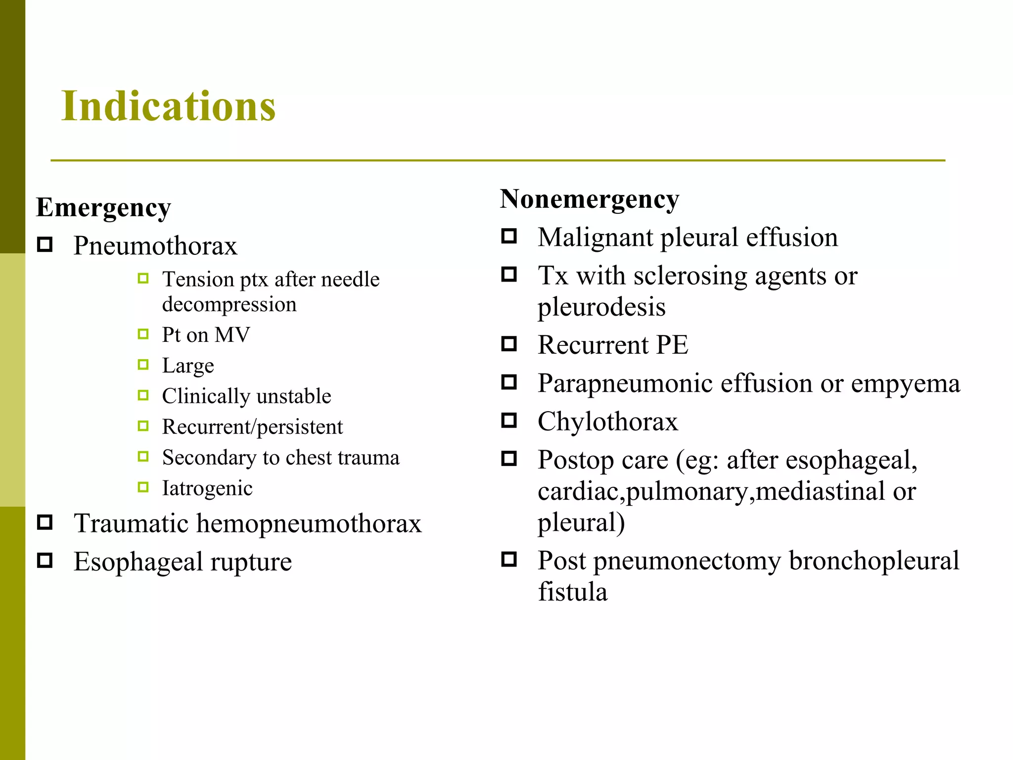
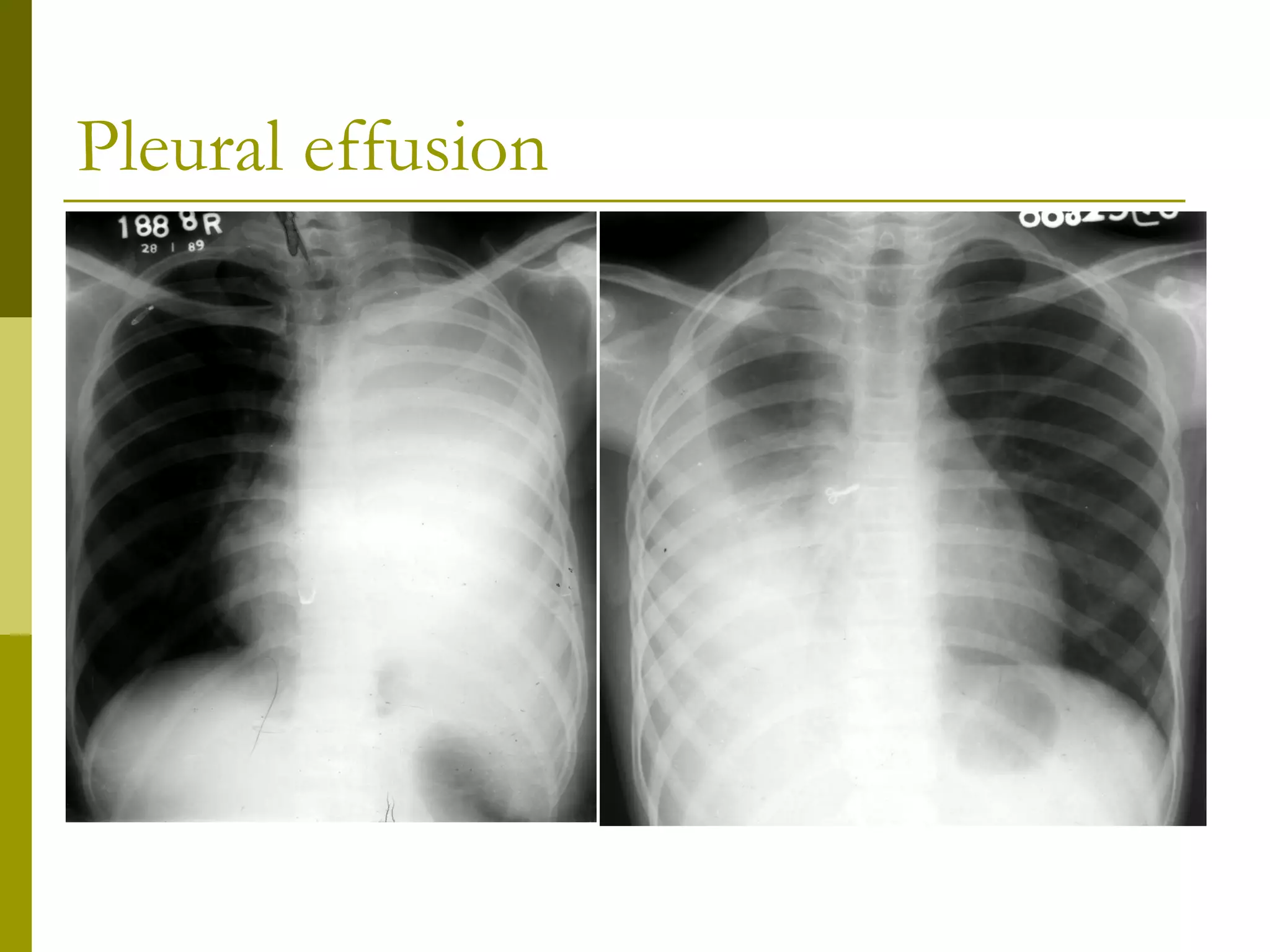
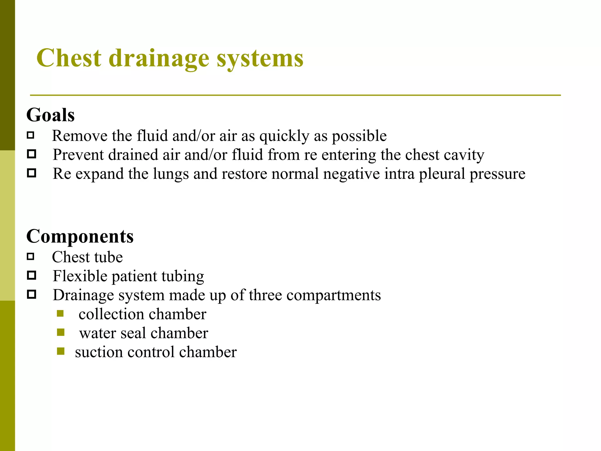
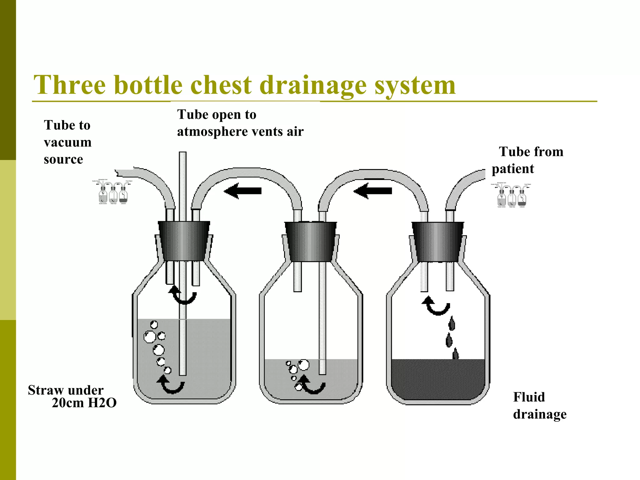
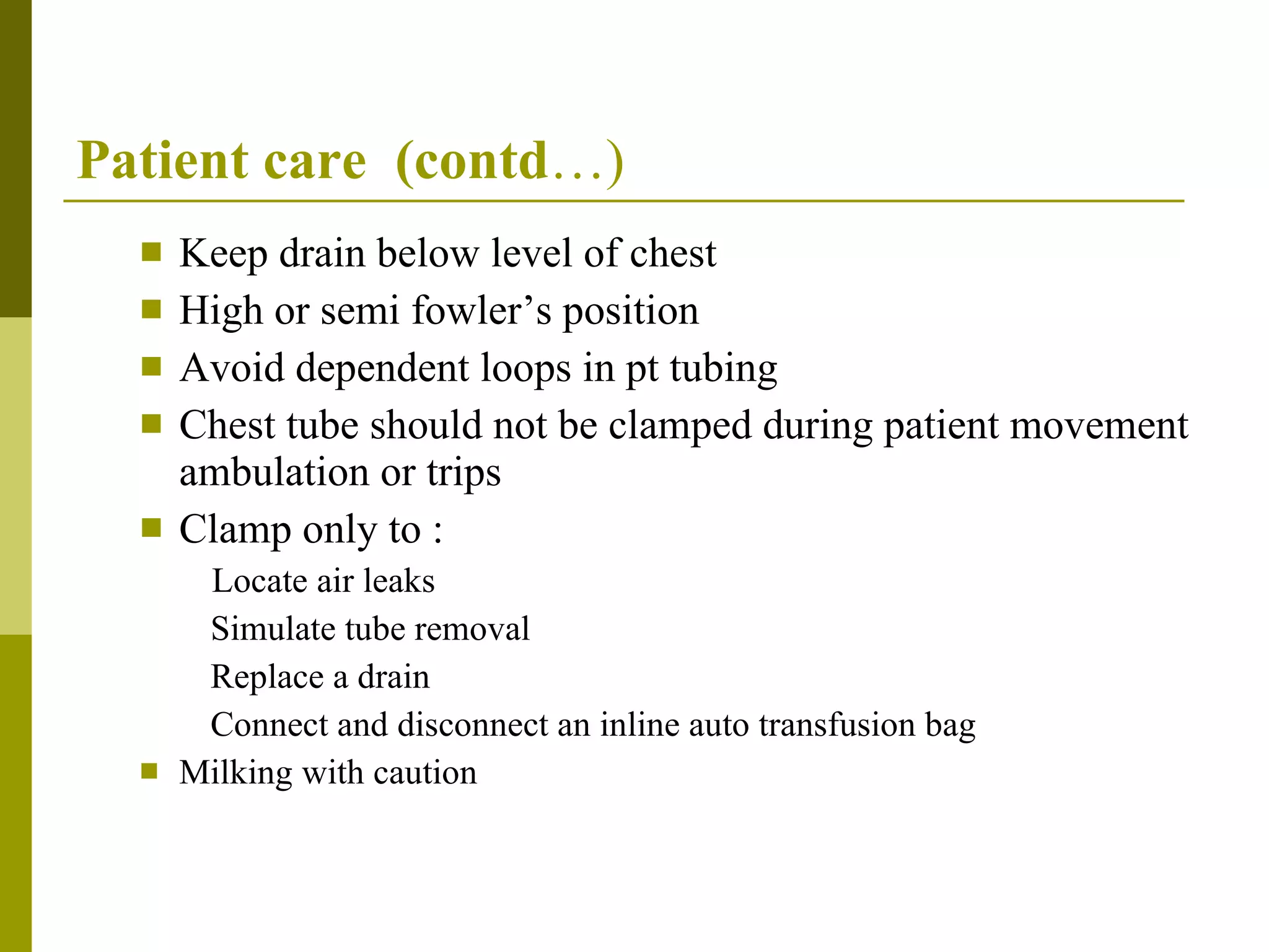
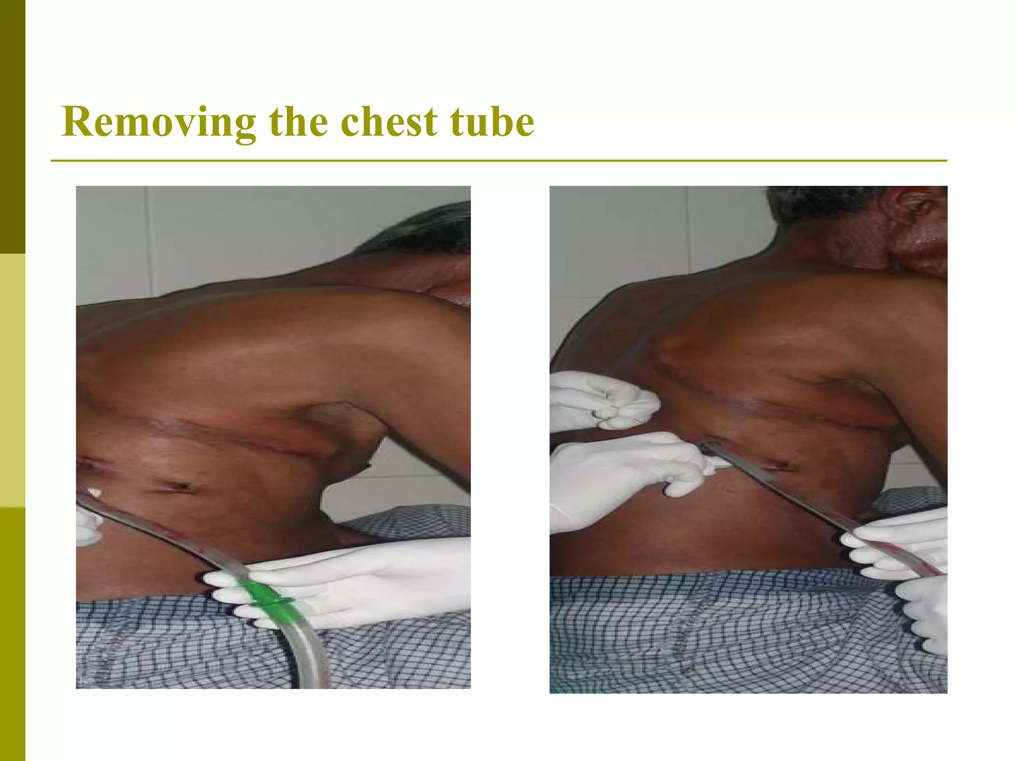
CHEST DRAINS Presenter:  Dr.Nishad.P.K Moderator :Prof: Lokesh   AIIMS  , NewDelhi
Anatomy  Pleural fluid separates parietal and visceral pleural surfaces Amount of pleural fluid in 24  hrs:0.3ml/kg or 25 ml Natural tendency of lung to recoil v/s adherence of pleura Negative intrapleural pressure  keeps the lung expanded during inspiration :-8cmH2O expiration:-4cmH2O Air, fluid or blood in pleural cavity  disruption of –ve IPP leads to lung collapse Lung Visceral pleura Parietal pleura
Physiology   Inspiration  Expiration
Indications   Emergency   Pneumothorax Tension ptx after needle decompression Pt on MV Large Clinically unstable Recurrent/persistent Secondary to chest trauma Iatrogenic  Traumatic hemopneumothorax Esophageal rupture Nonemergency Malignant pleural effusion Tx with sclerosing agents or pleurodesis Recurrent PE Parapneumonic effusion or empyema Chylothorax Postop care (eg: after esophageal, cardiac,pulmonary,mediastinal or pleural) Post pneumonectomy bronchopleural fistula
Pleural effusion
Pre-drainage risk assessment Careful clinical evaluation Differentiate between Pneumothorax and bullous disease Collapse and pleural effusion Risk of hem/g: correct any coagulopathy /platelet defect Contraindications   Absolute  Lung completely adherent to chest wall  Relative  Bleeding diathesis Pt on anticoagulants
Pneumothorax   Lung  bulla
Chest drainage systems Goals  Remove the fluid and/or air as quickly as possible Prevent drained air and/or fluid from re entering the chest cavity Re expand the lungs and restore normal negative intra pleural pressure Components Chest tube Flexible patient tubing Drainage system made up of three compartments collection chamber water seal chamber suction control chamber
Chest tubes 20 inches long,4-6 eyelets, radio opaque line Three  types  1.Thoracotomy chest tube- Straight, right angled Silicon / PVC 2.Trocar chest tube (2-3 eyelets) 3.Malecot catheter
Chest tubes
Chest tube size Size :   Infants and young children :8-12 F  Children and young adults:16-20 F  Most adults  :24-32 F  Large adults  : 36-40 F  Diameter depends on Size of pt Type of drainage (air/fluid) Duration of drainage
Patient tubing 6 foot tube connects chest tube to collection chamber Clear ,flexible and sufficiently strong Adv: 1. pt can turn and move in bed 2.minimize the chance that a deep breath could draw    drainage back up into chest b c a a b c
Physics and physiological aspects Flow depends on 1.Length of tube 2.Inner diameter of tube 3.Amount of negative pressure applied Air  : laminar flow   :Hagen–Poiseuille equation   V  =  π R 4   Δ P/8 η L Hydropneumothorax : Turbulent flow : Fanning equation V =  π 2 r 5 P/fl
One bottle chest drainage system Water seal –low resistance one way valve  Positive pressure > +2cm H2O Tidalling  –pressure changes in the pleural space with breathing seen as fluctuations Combination of water seal and fluid collecton bottle Tube from patient Tube open to atmosphere vents air
Physics and physiological aspects Distal end of drainage tube 2 cm below water ( the depth determines the hydrostatic pressure needed to overcome during expiration ) Collection chamber always 100 cm below the chest   ( to prevent the chamber fluid getting sucked up the tube during obstructed inspiration) Large diameter collection chamber (20 cm diameter) ( to prevent loss of under water seal as water moves up the drainage tube during deep inspiration)
Two bottle chest drainage system Collection bottle and water seal Amount and rate of fluid drainage can be measured Water seal remain fixed Rely on gravity to create pressure gradient Tube from patient Tube open to atmosphere vents air 2cm fluid Fluid drainage
Three bottle chest drainage system Straw under  20cm H2O Tube to vacuum source Tube open to atmosphere vents air Tube from patient Fluid drainage
Contd..   The  depth of the water  in the suction bottle determines the amount of negative pressure that can be transmitted to the chest,  NOT the reading on the vacuum regulator Expiratory positive pressure from the patient helps push air and fluid out of the chest (cough, Valsalva) Gravity helps fluid drainage as long as the chest drainage system is below the level of the chest Suction can improve the speed at which air and fluid are pulled from the chest
Draw backs of three bottle system Bulky with 16 pieces and 17 connections  Lot of time to set up Potential for error or contamination high Expense for hospital to clean ,sterilize and track the processing
Disposable chest drainage systems In 1967, a one-piece, disposable plastic box was introduced The box did everything the bottles did – and more Compact, sterile and disposable Chambers corresponds to bottle in three bottle system
From bottles to a box To suction From patient Suction control chamber Water seal chamber Collection chamber from patient Collection bottle Water seal bottle Suction control bottle
Contd…  Collection chamber  :Amount and rate of fluid drainage Water seal chamber :Asymmetric u tube,one way valve,used to measure IPP Dry seal chest drain: mechanical one way valve Suction control chamber: protect the pt from excess suction pressure wet: regulate by height of column of water dry: mechanical screw type  valve:  varies the size opening to vaccum  source calibrated spring loaded  self regulating mechanism Positive pressure relief valve-that vent accumulated pressure >2cmH2O
Heimlich valve Mechanical one way valve  Allow air to escape from chest and prevent air from entering chest Adv :  Does not require water to operate Not position sensitive Early ambulation of the patient Disadv :  Less patient assessment information  Cannot see changes in IPP
From box to bedside
Our drainage systems  a b c d
Setting up a chest drain system Thoracostomy  Setting up a drainage unit  Making proper connecting and applying suction
Equipments  Sterile gloves and gown Skin antiseptic solution Sterile drapes Gauze swabs Syringes and needles Local anesthetic Scalpel and blade Suture (“1” silk) Dressing  Curved Kelly clamps
Equipments Chest tube  Connecting tubing Closed drainage system
Patient preparation Explain the procedure Informed written consent Verify the site of abnormality Mark the site on patient’s chest Premedication  Monitor O2 saturation and supplemental O2
Patient position Supine ,slightly rotated with arm on side of lesion behind patient’s head to expose the axillary area  Or sit  upright leaning over an adjacent table with a pillow Or lateral decubitus position
Insertion site Triangle of safety(in mid axillary line)  - 4 th  or 5 th  ICS Ant.border of latissimus dorsi Lateral border of pectoralis major Line superior to horzontal level of nipple Apex below axilla Midclavicular -2 nd  ICS Thick pectoralis major –difficult to penetrate Scar-cosmetic
Direction of tube Air :anterior and superior (towards apex) Fluid :posterior and inferior (towards base) Surgical Any tube position can be effective at draining air or fluid and an effectively functioning chest tube should not be  repositioned solely because of position in CXR
Procedure  Strict aseptic technique  Skin preparation
Procedure contd..
 
 
Suturing and sterile dressing
Improper chest tube fixation
Get a CXR done
Complications Wound infection Empyema  Infective  Drain failure(dislodgement,kinked,blocked) Re expansion pulmonary edema Bronchopleural fistula pneumothorax Positional Pain  Placement outwith pleural cavity-( s/c,intra abdominal,solid organ) Puncture of solid organ (liver,spleen,heart,lung,oesophagus) Puncture of inter costal artery- hemothorax Insertion on incorrect side Inter costal neuralgia S/C emphysema Insertional
 
Patient care Respiration  Rate, regularity, depth and ease  Breath sounds Deep breaths and cough Splintage  of thoracic incision with pillow Knowledge level Pain control Vital signs Patient position/movement Encourage movement Gravity drainage v/s suction If discontinued from suction tube should be open to air
Patient care  (contd …) Keep drain below level of chest High or semi fowler’s position Avoid dependent loops in pt tubing Chest tube should not be clamped during patient movement ambulation or trips Clamp only to : Locate air leaks Simulate tube removal Replace a drain Connect and disconnect an inline auto transfusion bag Milking with caution
Patient care Chest tube site/dressing Dressing dry and intact Palpate for s/c  emphysema If present ,take down the dressing and inspect site, look for the eyelets. Tubing   Regular inspection for leaks, kink, dependent  loops compression/occlusion Drain fluid  Samples Monitor volume, rate, colour and characteristics
Patient care  (contd…) Water seal  Water seal  is filled to appropriate level Water level moves on patient breaths ( tidalling ) If no   :  Kinked, clamped, lying on tubing Dependent fluid filled loop Lung tissue or adhesions are blocking the eyelets No more air leaking to pleural space and  lung has re-expanded To locate air leaks Suction  :check connections and tubing typical suction level: -15 to – 20 cmH2O
Timing of chest tube removal Depends on indication Pneumothorax  Bubbling movement has ceased Lung fully expanded in CXR Controversial: Duration of observation Clamping the tube Get CXR 12-24 hrs after last air leak Pleural fluid drainage Volume < 100 ml in 24 hrs Serous fluid Lung re expanded and clinical status improved No fresh or altered blood coming out of chest tube
Removing the chest tube Explain the procedure to the patient Prevent risk of pneumothorax End expiration  v/s  end inspiration If on MV :End expiration Two people – Instruct the patient and pull the tube _ Occlude the insertion site Tighten the suture and occlusive dressing CXR 12 -24 hrs  after removal
Removing the chest tube
Looking towards future-mobile chest drains Facilitate early ambulation Reduce hospital stay Air alone-oneway valve:Heimlich valve For both fluid and air :mini chest drain
 

Chest Drains

  • 1.
    CHEST DRAINS Presenter: Dr.Nishad.P.K Moderator :Prof: Lokesh AIIMS , NewDelhi
  • 2.
    Anatomy Pleuralfluid separates parietal and visceral pleural surfaces Amount of pleural fluid in 24 hrs:0.3ml/kg or 25 ml Natural tendency of lung to recoil v/s adherence of pleura Negative intrapleural pressure keeps the lung expanded during inspiration :-8cmH2O expiration:-4cmH2O Air, fluid or blood in pleural cavity disruption of –ve IPP leads to lung collapse Lung Visceral pleura Parietal pleura
  • 3.
    Physiology Inspiration Expiration
  • 4.
    Indications Emergency Pneumothorax Tension ptx after needle decompression Pt on MV Large Clinically unstable Recurrent/persistent Secondary to chest trauma Iatrogenic Traumatic hemopneumothorax Esophageal rupture Nonemergency Malignant pleural effusion Tx with sclerosing agents or pleurodesis Recurrent PE Parapneumonic effusion or empyema Chylothorax Postop care (eg: after esophageal, cardiac,pulmonary,mediastinal or pleural) Post pneumonectomy bronchopleural fistula
  • 5.
  • 6.
    Pre-drainage risk assessmentCareful clinical evaluation Differentiate between Pneumothorax and bullous disease Collapse and pleural effusion Risk of hem/g: correct any coagulopathy /platelet defect Contraindications Absolute Lung completely adherent to chest wall Relative Bleeding diathesis Pt on anticoagulants
  • 7.
    Pneumothorax Lung bulla
  • 8.
    Chest drainage systemsGoals Remove the fluid and/or air as quickly as possible Prevent drained air and/or fluid from re entering the chest cavity Re expand the lungs and restore normal negative intra pleural pressure Components Chest tube Flexible patient tubing Drainage system made up of three compartments collection chamber water seal chamber suction control chamber
  • 9.
    Chest tubes 20inches long,4-6 eyelets, radio opaque line Three types 1.Thoracotomy chest tube- Straight, right angled Silicon / PVC 2.Trocar chest tube (2-3 eyelets) 3.Malecot catheter
  • 10.
  • 11.
    Chest tube sizeSize : Infants and young children :8-12 F Children and young adults:16-20 F Most adults :24-32 F Large adults : 36-40 F Diameter depends on Size of pt Type of drainage (air/fluid) Duration of drainage
  • 12.
    Patient tubing 6foot tube connects chest tube to collection chamber Clear ,flexible and sufficiently strong Adv: 1. pt can turn and move in bed 2.minimize the chance that a deep breath could draw drainage back up into chest b c a a b c
  • 13.
    Physics and physiologicalaspects Flow depends on 1.Length of tube 2.Inner diameter of tube 3.Amount of negative pressure applied Air : laminar flow :Hagen–Poiseuille equation V = π R 4 Δ P/8 η L Hydropneumothorax : Turbulent flow : Fanning equation V = π 2 r 5 P/fl
  • 14.
    One bottle chestdrainage system Water seal –low resistance one way valve Positive pressure > +2cm H2O Tidalling –pressure changes in the pleural space with breathing seen as fluctuations Combination of water seal and fluid collecton bottle Tube from patient Tube open to atmosphere vents air
  • 15.
    Physics and physiologicalaspects Distal end of drainage tube 2 cm below water ( the depth determines the hydrostatic pressure needed to overcome during expiration ) Collection chamber always 100 cm below the chest ( to prevent the chamber fluid getting sucked up the tube during obstructed inspiration) Large diameter collection chamber (20 cm diameter) ( to prevent loss of under water seal as water moves up the drainage tube during deep inspiration)
  • 16.
    Two bottle chestdrainage system Collection bottle and water seal Amount and rate of fluid drainage can be measured Water seal remain fixed Rely on gravity to create pressure gradient Tube from patient Tube open to atmosphere vents air 2cm fluid Fluid drainage
  • 17.
    Three bottle chestdrainage system Straw under 20cm H2O Tube to vacuum source Tube open to atmosphere vents air Tube from patient Fluid drainage
  • 18.
    Contd.. The depth of the water in the suction bottle determines the amount of negative pressure that can be transmitted to the chest, NOT the reading on the vacuum regulator Expiratory positive pressure from the patient helps push air and fluid out of the chest (cough, Valsalva) Gravity helps fluid drainage as long as the chest drainage system is below the level of the chest Suction can improve the speed at which air and fluid are pulled from the chest
  • 19.
    Draw backs ofthree bottle system Bulky with 16 pieces and 17 connections Lot of time to set up Potential for error or contamination high Expense for hospital to clean ,sterilize and track the processing
  • 20.
    Disposable chest drainagesystems In 1967, a one-piece, disposable plastic box was introduced The box did everything the bottles did – and more Compact, sterile and disposable Chambers corresponds to bottle in three bottle system
  • 21.
    From bottles toa box To suction From patient Suction control chamber Water seal chamber Collection chamber from patient Collection bottle Water seal bottle Suction control bottle
  • 22.
    Contd… Collectionchamber :Amount and rate of fluid drainage Water seal chamber :Asymmetric u tube,one way valve,used to measure IPP Dry seal chest drain: mechanical one way valve Suction control chamber: protect the pt from excess suction pressure wet: regulate by height of column of water dry: mechanical screw type valve: varies the size opening to vaccum source calibrated spring loaded self regulating mechanism Positive pressure relief valve-that vent accumulated pressure >2cmH2O
  • 23.
    Heimlich valve Mechanicalone way valve Allow air to escape from chest and prevent air from entering chest Adv : Does not require water to operate Not position sensitive Early ambulation of the patient Disadv : Less patient assessment information Cannot see changes in IPP
  • 24.
    From box tobedside
  • 25.
  • 26.
    Setting up achest drain system Thoracostomy Setting up a drainage unit Making proper connecting and applying suction
  • 27.
    Equipments Sterilegloves and gown Skin antiseptic solution Sterile drapes Gauze swabs Syringes and needles Local anesthetic Scalpel and blade Suture (“1” silk) Dressing Curved Kelly clamps
  • 28.
    Equipments Chest tube Connecting tubing Closed drainage system
  • 29.
    Patient preparation Explainthe procedure Informed written consent Verify the site of abnormality Mark the site on patient’s chest Premedication Monitor O2 saturation and supplemental O2
  • 30.
    Patient position Supine,slightly rotated with arm on side of lesion behind patient’s head to expose the axillary area Or sit upright leaning over an adjacent table with a pillow Or lateral decubitus position
  • 31.
    Insertion site Triangleof safety(in mid axillary line) - 4 th or 5 th ICS Ant.border of latissimus dorsi Lateral border of pectoralis major Line superior to horzontal level of nipple Apex below axilla Midclavicular -2 nd ICS Thick pectoralis major –difficult to penetrate Scar-cosmetic
  • 32.
    Direction of tubeAir :anterior and superior (towards apex) Fluid :posterior and inferior (towards base) Surgical Any tube position can be effective at draining air or fluid and an effectively functioning chest tube should not be repositioned solely because of position in CXR
  • 33.
    Procedure Strictaseptic technique Skin preparation
  • 34.
  • 35.
  • 36.
  • 37.
  • 38.
  • 39.
  • 40.
    Complications Wound infectionEmpyema Infective Drain failure(dislodgement,kinked,blocked) Re expansion pulmonary edema Bronchopleural fistula pneumothorax Positional Pain Placement outwith pleural cavity-( s/c,intra abdominal,solid organ) Puncture of solid organ (liver,spleen,heart,lung,oesophagus) Puncture of inter costal artery- hemothorax Insertion on incorrect side Inter costal neuralgia S/C emphysema Insertional
  • 41.
  • 42.
    Patient care Respiration Rate, regularity, depth and ease Breath sounds Deep breaths and cough Splintage of thoracic incision with pillow Knowledge level Pain control Vital signs Patient position/movement Encourage movement Gravity drainage v/s suction If discontinued from suction tube should be open to air
  • 43.
    Patient care (contd …) Keep drain below level of chest High or semi fowler’s position Avoid dependent loops in pt tubing Chest tube should not be clamped during patient movement ambulation or trips Clamp only to : Locate air leaks Simulate tube removal Replace a drain Connect and disconnect an inline auto transfusion bag Milking with caution
  • 44.
    Patient care Chesttube site/dressing Dressing dry and intact Palpate for s/c emphysema If present ,take down the dressing and inspect site, look for the eyelets. Tubing Regular inspection for leaks, kink, dependent loops compression/occlusion Drain fluid Samples Monitor volume, rate, colour and characteristics
  • 45.
    Patient care (contd…) Water seal Water seal is filled to appropriate level Water level moves on patient breaths ( tidalling ) If no : Kinked, clamped, lying on tubing Dependent fluid filled loop Lung tissue or adhesions are blocking the eyelets No more air leaking to pleural space and lung has re-expanded To locate air leaks Suction :check connections and tubing typical suction level: -15 to – 20 cmH2O
  • 46.
    Timing of chesttube removal Depends on indication Pneumothorax Bubbling movement has ceased Lung fully expanded in CXR Controversial: Duration of observation Clamping the tube Get CXR 12-24 hrs after last air leak Pleural fluid drainage Volume < 100 ml in 24 hrs Serous fluid Lung re expanded and clinical status improved No fresh or altered blood coming out of chest tube
  • 47.
    Removing the chesttube Explain the procedure to the patient Prevent risk of pneumothorax End expiration v/s end inspiration If on MV :End expiration Two people – Instruct the patient and pull the tube _ Occlude the insertion site Tighten the suture and occlusive dressing CXR 12 -24 hrs after removal
  • 48.
  • 49.
    Looking towards future-mobilechest drains Facilitate early ambulation Reduce hospital stay Air alone-oneway valve:Heimlich valve For both fluid and air :mini chest drain
  • 50.