The document provides an overview of the 8051 microcontroller architecture, detailing its memory structure, including internal and external data memory, SFRs, and program memory specifications. It outlines timers, interrupts, instruction timing, and the various programming aspects related to C, including the usage of specific data types and interrupts for background tasks. Additionally, it discusses design problems and their solutions via practical examples, focusing on measurement and interfacing challenges.
![CSE 477 8051 Overview 6
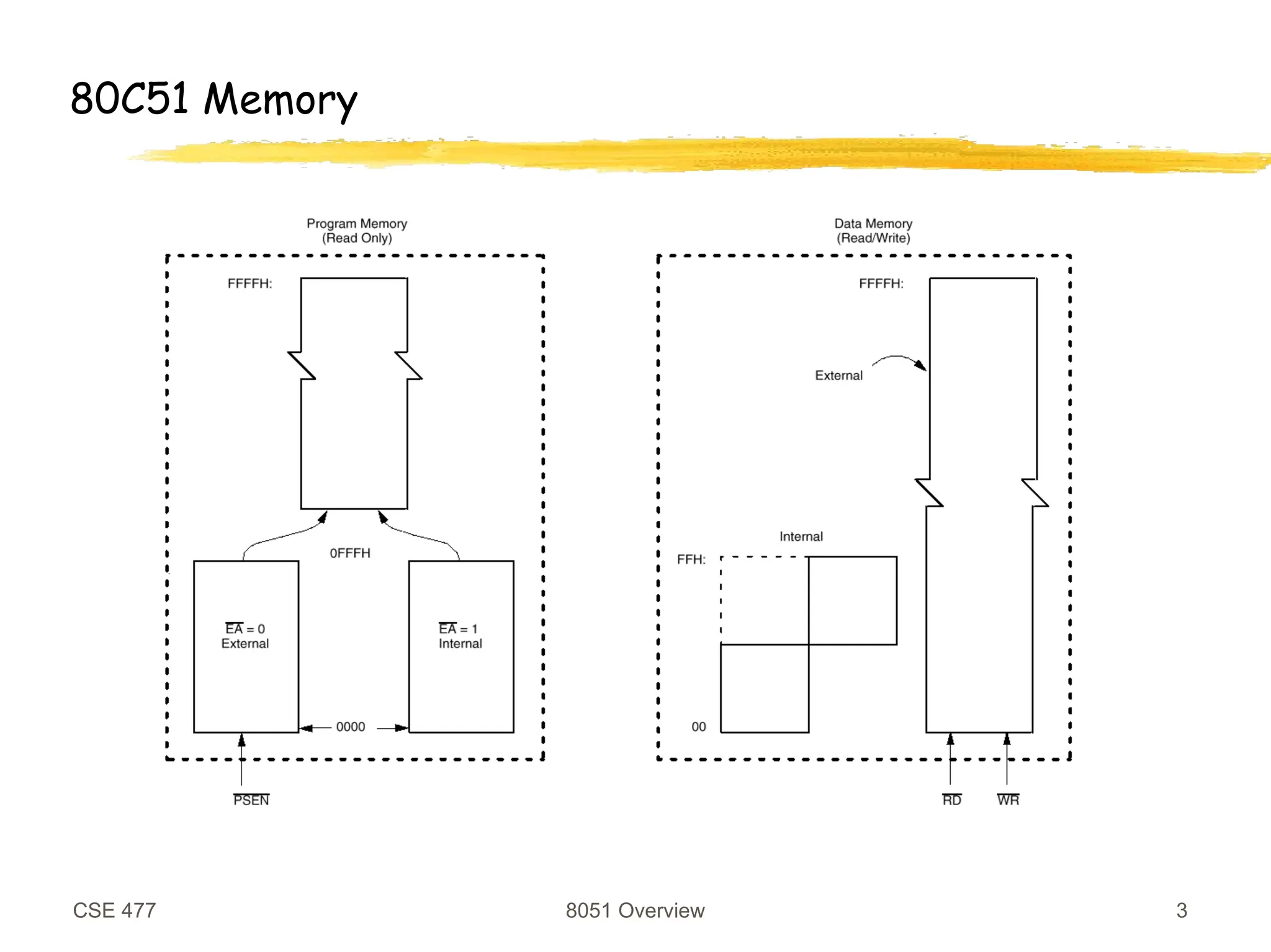
Program Memory
Program and Data memory are separate
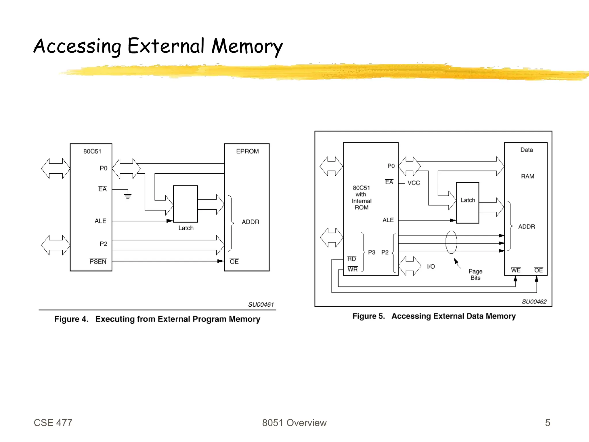
Can be internal and/or external
20K internal flash for the Atmel controller
Read-only
Instructions
Constant data
char code table[5] =
{‘1’,‘2’,‘3’,‘4’,‘5’} ;
Compiler uses instructions for moving “immediate” data](https://image.slidesharecdn.com/memory-240930070510-90d5b779/75/MEMORY-ppt-8051-8052-MEMORY-MANEGEMENT-MEMORY-DESCRIPTION-6-2048.jpg)


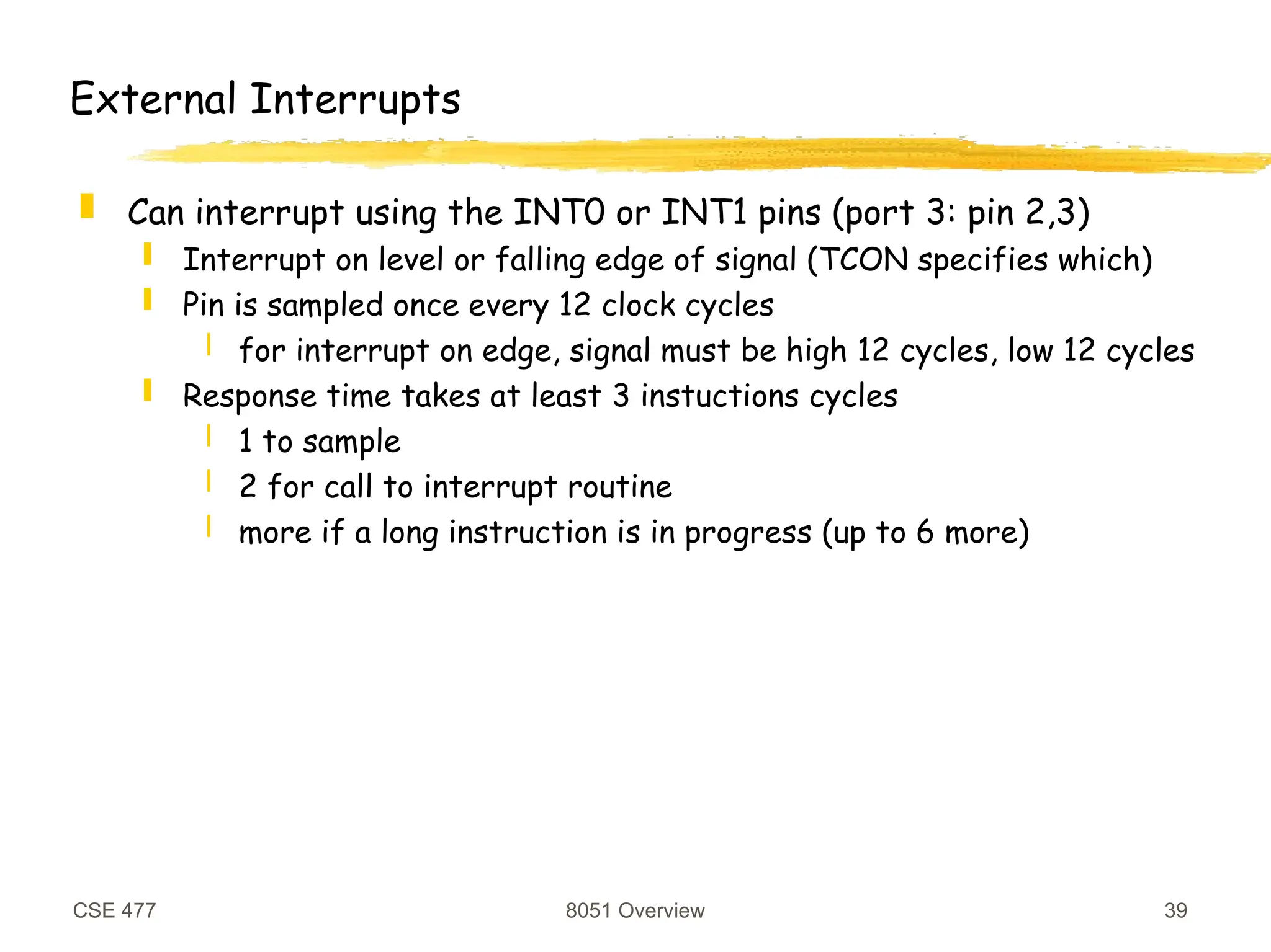
![CSE 477 8051 Overview 38
Re-entrant Functions
A function can be called simultaneously be different processes
Recursive functions must be re-entrant
Functions called by interrupt code and non-interrupt code must
be re-entrant
Keil C functions by default are not re-entrant
Does not use the stack for everything
Use the reentrant specifier to make a function re-entrant
int calc (char i, int b) reentrant {
int x;
x = table[i];
return (x * b);
}](https://image.slidesharecdn.com/memory-240930070510-90d5b779/75/MEMORY-ppt-8051-8052-MEMORY-MANEGEMENT-MEMORY-DESCRIPTION-38-2048.jpg)