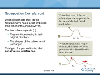
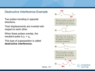
SlideShare a Scribd company logo
1 of 56
Download to read offline
Chapter 18
Superposition and Standing Waves
Waves vs. Particles
Waves are very different from particles.
Particles have zero size. Waves have a characteristic size – their
wavelength.
Multiple particles must exist at
different locations.
Multiple waves can combine at one point in
the same medium – they can be present at
the same location.
Introduction
Quantization
When waves are combined in systems with boundary conditions, only certain
allowed frequencies can exist.
 We say the frequencies are quantized.
 Quantization is at the heart of quantum mechanics, studied later
The analysis of waves under boundary conditions explains many quantum
phenomena.
Quantization can be used to understand the behavior of the wide array of musical
instruments that are based on strings and air columns.
Waves can also combine when they have different frequencies.
Introduction
Superposition Principle
Waves can be combined in the same location in space.
To analyze these wave combinations, use the superposition principle:
If two or more traveling waves are moving through a medium, the resultant value
of the wave function at any point is the algebraic sum of the values of the wave
functions of the individual waves.
Waves that obey the superposition principle are linear waves.
 For mechanical waves, linear waves have amplitudes much smaller than
their wavelengths.
Section 18.1
Superposition and Interference
Two traveling waves can pass through each other without being destroyed or
altered.
 A consequence of the superposition principle.
The combination of separate waves in the same region of space to produce a
resultant wave is called interference.
 The term interference has a very specific usage in physics.
 It means waves pass through each other.
Section 18.1
Superposition Example
Two pulses are traveling in opposite
directions (a).
 The wave function of the pulse
moving to the right is y1 and for the
one moving to the left is y2.
The pulses have the same speed but
different shapes.
The displacement of the elements is
positive for both.
When the waves start to overlap (b),
the resultant wave function is y1 + y2.
Section 18.1
Superposition Example, cont
When crest meets crest (c) the
resultant wave has a larger amplitude
than either of the original waves.
The two pulses separate (d).
 They continue moving in their
original directions.
 The shapes of the pulses remain
unchanged.
This type of superposition is called
constructive interference.
Section 18.1
Destructive Interference Example
Two pulses traveling in opposite
directions.
Their displacements are inverted with
respect to each other.
When these pulses overlap, the
resultant pulse is y1 + y2.
This type of superposition is called
destructive interference.
Section 18.1
Types of Interference, Summary
Constructive interference occurs when the displacements caused by the two
pulses are in the same direction.
 The amplitude of the resultant pulse is greater than either individual pulse.
Destructive interference occurs when the displacements caused by the two
pulses are in opposite directions.
 The amplitude of the resultant pulse is less than either individual pulse.
Section 18.1
Analysis Model
The superposition principle is the centerpiece of the analysis model called waves
in interference.
Applies in many situations
 They exhibit interesting phenomena with practical applications.
Section 18.1
Superposition of Sinusoidal Waves
Assume two waves are traveling in the same direction in a linear medium, with
the same frequency, wavelength and amplitude.
The waves differ only in phase:
 y1 = A sin (kx - wt)
 y2 = A sin (kx - wt + f)
 y = y1+y2 = 2A cos (f /2) sin (kx - wt + f /2)
The resultant wave function, y, is also sinusoida.l
The resultant wave has the same frequency and wavelength as the original
waves.
The amplitude of the resultant wave is 2A cos (f / 2) .
The phase of the resultant wave is f / 2.
Sinusoidal Waves with Constructive Interference
When f = 0, then cos (f/2) = 1
The amplitude of the resultant wave is 2A.
 The crests of the two waves are at the same location in space.
The waves are everywhere in phase.
The waves interfere constructively.
In general, constructive interference occurs when cos (Φ/2) = ± 1.
 That is, when Φ = 0, π, 2 π, … rad
 When Φ is an even multiple of π
Section 18.1
Sinusoidal Waves with Destructive Interference
When f = p, then cos (f/2) = 0
 Also any odd multiple of p
The amplitude of the resultant wave is 0.
 See the straight red-brown line in the figure.
The waves interfere destructively.
Section 18.1
Sinusoidal Waves, General Interference
When f is other than 0 or an even multiple of p, the amplitude of the resultant is
between 0 and 2A.
The wave functions still add
The interference is neither constructive nor destructive.
Section 18.1
Sinusoidal Waves, Summary of Interference
Constructive interference occurs when f = np where n is an even integer
(including 0).
 Amplitude of the resultant is 2A
Destructive interference occurs when f = np where n is an odd integer.
 Amplitude is 0
General interference occurs when 0 < f < np
 Amplitude is 0 < Aresultant < 2A
Section 18.1
Sinusoidal Waves, Interference with Difference Amplitudes
Constructive interference occurs when f = n p where n is an even integer
(including 0).
 Amplitude of the resultant is the sum of the amplitudes of the waves
Destructive interference occurs when f = n p where n is an odd integer.
 Amplitude is less, but the amplitudes do not completely cancel
Section 18.1
Interference in Sound Waves
Sound from S can reach R by two
different paths.
The distance along any path from
speaker to receiver is called the path
length, r.
The lower path length, r1, is fixed.
The upper path length, r2, can be
varied.
Whenever Dr = |r2 – r1| = n l,
constructive interference occurs.
 n = 0, 1, …
A maximum in sound intensity is
detected at the receiver.
Section 18.1
Interference in Sound Waves, 2
Whenever Dr = |r2 – r1| = (nl)/2 (n is odd), destructive interference occurs.
No sound is detected at the receiver.
A phase difference may arise between two waves generated by the same source
when they travel along paths of unequal lengths.
Section 18.1
Standing Waves
Assume two waves with the same
amplitude, frequency and wavelength,
traveling in opposite directions in a
medium.
The waves combine in accordance with
the waves in interference model.
y1 = A sin (kx – wt) and
y2 = A sin (kx + wt)
They interfere according to the
superposition principle.
Section 18.2
Standing Waves, cont
The resultant wave will be y = (2A sin kx) cos wt.
This is the wave function of a standing wave.
 There is no kx – wt term, and therefore it is not a traveling wave.
In observing a standing wave, there is no sense of motion in the direction of
propagation of either of the original waves.
Section 18.2
Standing Wave Example
Note the stationary outline that results from the superposition of two identical
waves traveling in opposite directions.
The amplitude of the simple harmonic motion of a given element is 2A sin kx.
 This depends on the location x of the element in the medium.
Each individual element vibrates at w
Section 18.2
Note on Amplitudes
There are three types of amplitudes used in describing waves.
 The amplitude of the individual waves, A
 The amplitude of the simple harmonic motion of the elements in the medium,
 2A sin kx
 A given element in the standing wave vibrates within the constraints of the
envelope function 2 A sin k x.
 The amplitude of the standing wave, 2A
Section 18.2
Standing Waves, Definitions
A node occurs at a point of zero amplitude.
 These correspond to positions of x where
An antinode occurs at a point of maximum displacement, 2A.
 These correspond to positions of x where
0,1, 2, 3,
2
n
x n
l
 
1, 3, 5,
4
n
x n
l
 
Section 18.2
Features of Nodes and Antinodes
The distance between adjacent antinodes is l/2.
The distance between adjacent nodes is l/2.
The distance between a node and an adjacent antinode is l/4.
Section 18.2
Nodes and Antinodes, cont
The diagrams above show standing-wave patterns produced at various times
by two waves of equal amplitude traveling in opposite directions.
In a standing wave, the elements of the medium alternate between the
extremes shown in (a) and (c).
Section 18.2
Standing Waves in a String
Consider a string fixed at both ends
The string has length L.
Waves can travel both ways on the
string.
Standing waves are set up by a
continuous superposition of waves
incident on and reflected from the ends.
There is a boundary condition on the
waves.
The ends of the strings must
necessarily be nodes.
 They are fixed and therefore must have
zero displacement.
Section 18.3
Standing Waves in a String, 2
The boundary condition results in the string having a set of natural patterns of
oscillation, called normal modes.
 Each mode has a characteristic frequency.
 This situation in which only certain frequencies of oscillations are allowed is called
quantization.
 The normal modes of oscillation for the string can be described by imposing
the requirements that the ends be nodes and that the nodes and antinodes
are separated by l/4.
We identify an analysis model called waves under boundary conditions.
Section 18.3
Standing Waves in a String, 3
This is the first normal mode that is
consistent with the boundary
conditions.
There are nodes at both ends.
There is one antinode in the middle.
This is the longest wavelength mode:
 ½l1 = L so l1 = 2L
The section of the standing wave
between nodes is called a loop.
In the first normal mode, the string
vibrates in one loop.
Section 18.3
Standing Waves in a String, 4
Consecutive normal modes add a loop at each step.
 The section of the standing wave from one node to the next is called a loop.
The second mode (c) corresponds to to l = L.
The third mode (d) corresponds to l = 2L/3.
Section 18.3
Standing Waves on a String, Summary
The wavelengths of the normal modes for a string of length L fixed at both ends
are ln = 2L / n n = 1, 2, 3, …
 n is the nth normal mode of oscillation
 These are the possible modes for the string:
The natural frequencies are
 Also called quantized frequencies
ƒ
2 2
n
v n T
n
L L 
 
Section 18.3
Waves on a String, Harmonic Series
The fundamental frequency corresponds to n = 1.
 It is the lowest frequency, ƒ1
The frequencies of the remaining natural modes are integer multiples of the
fundamental frequency.
 ƒn = nƒ1
Frequencies of normal modes that exhibit this relationship form a harmonic
series.
The normal modes are called harmonics.
Section 18.3
Musical Note of a String
The musical note is defined by its fundamental frequency.
The frequency of the string can be changed by changing either its length or its
tension.
Section 18.3
Harmonics, Example
A middle “C” string on a piano has a fundamental frequency of 262 Hz. What are
the next two harmonics of this string?
 ƒ1 = 262 Hz
 ƒ2 = 2ƒ1 = 524 Hz
 ƒ3 = 3ƒ1 = 786 Hz
Section 18.3
Standing Wave on a String, Example Set-Up
One end of the string is attached to a vibrating blade.
The other end passes over a pulley with a hanging mass attached to the end.
 This produces the tension in the string.
The string is vibrating in its second harmonic.
Section 18.3
Resonance
A system is capable of oscillating in one
or more normal modes.
Assume we drive a string with a
vibrating blade.
If a periodic force is applied to such a
system, the amplitude of the resulting
motion of the string is greatest when
the frequency of the applied force is
equal to one of the natural frequencies
of the system.
This phenomena is called resonance.
Section 18.4
Resonance, cont.
Because an oscillating system exhibits a large amplitude when driven at any of
its natural frequencies, these frequencies are referred to as resonance
frequencies.
If the system is driven at a frequency that is not one of the natural frequencies,
the oscillations are of low amplitude and exhibit no stable pattern.
Section 18.4
Standing Waves in Air Columns
Standing waves can be set up in air columns as the result of interference
between longitudinal sound waves traveling in opposite directions.
The phase relationship between the incident and reflected waves depends upon
whether the end of the pipe is opened or closed.
Waves under boundary conditions model can be applied.
Section 18.5
Standing Waves in Air Columns, Closed End
A closed end of a pipe is a displacement node in the standing wave.
 The rigid barrier at this end will not allow longitudinal motion in the air.
The closed end corresponds with a pressure antinode.
 It is a point of maximum pressure variations.
 The pressure wave is 90o out of phase with the displacement wave.
Section 18.5
Standing Waves in Air Columns, Open End
The open end of a pipe is a displacement antinode in the standing wave.
 As the compression region of the wave exits the open end of the pipe, the
constraint of the pipe is removed and the compressed air is free to expand
into the atmosphere.
The open end corresponds with a pressure node.
 It is a point of no pressure variation.
Section 18.5
Standing Waves in an Open Tube
Both ends are displacement
antinodes.
The fundamental frequency is v/2L.
 This corresponds to the first
diagram.
The higher harmonics are ƒn = nƒ1 =
n (v/2L) where n = 1, 2, 3, …
In a pipe open at both ends, the
natural frequencies of oscillation form
a harmonic series that includes all
integral multiples of the fundamental
frequency.
Section 18.5
Standing Waves in a Tube Closed at One End
The closed end is a displacement node.
The open end is a displacement
antinode.
The fundamental corresponds to ¼l
The frequencies are ƒn = nƒ = n (v/4L)
where n = 1, 3, 5, …
In a pipe closed at one end, the natural
frequencies of oscillation form a
harmonic series that includes only odd
integral multiples of the fundamental
frequency.
Section 18.5
Notes About Musical Instruments
As the temperature rises:
 Sounds produced by air columns become sharp
 Higher frequency
 Higher speed due to the higher temperature
 Sounds produced by strings become flat
 Lower frequency
 The strings expand due to the higher temperature.
 As the strings expand, their tension decreases.
Section 18.5
More About Musical Instruments
Musical instruments based on air columns are generally excited by resonance.
The air column is presented with a sound wave rich in many frequencies.
The sound is provided by:
 A vibrating reed in woodwinds
 Vibrations of the player’s lips in brasses
 Blowing over the edge of the mouthpiece in a flute
Section 18.5
Resonance in Air Columns, Example
A tuning fork is placed near the top of
the tube.
When L corresponds to a resonance
frequency of the pipe, the sound is
louder.
The water acts as a closed end of a
tube.
The wavelengths can be calculated
from the lengths where resonance
occurs.
Section 18.5
Standing Waves in Rods
A rod is clamped in the middle.
It is stroked parallel to the rod.
The rod will oscillate.
The oscillations of the elements of the
rod are longitudinal.
The clamp forces a displacement node.
The ends of the rod are free to vibrate
and so will correspond to displacement
antinodes.
The first normal mode (shown) has a
wavelength of 2 L and a frequency of
ƒ = v / 2 L.
Section 18.6
Standing Waves in Rods, cont.
By clamping the rod at other points,
other normal modes of oscillation can
be produced.
Here the rod is clamped at L/4 from one
end.
This produces the second normal
mode.
Section 18.6
Standing Waves in Membranes
Two-dimensional oscillations may be set up in a flexible membrane stretched
over a circular hoop.
The resulting sound is not harmonic because the standing waves have
frequencies that are not related by integer multiples.
 The sound may be more correctly described as noise instead of music.
The fundamental frequency contains one nodal curve.
Section 18.6
Spatial and Temporal Interference
Spatial interference occurs when the amplitude of the oscillation in a medium
varies with the position in space of the element.
 This is the type of interference discussed so far.
Temporal interference occurs when waves are periodically in and out of phase.
 This is a superposition of two waves having slightly different frequencies.
 There is a temporal alternation between constructive and destructive
interference.
Section 18.7
Beats and Beat Frequency
Beating is the periodic variation in amplitude at a given point due to the
superposition of two waves having slightly different frequencies.
The number of amplitude maxima one hears per second is the beat frequency.
It equals the difference between the frequencies of the two sources.
The human ear can detect a beat frequency up to about 20 beats/sec.
Beats, Equations
The amplitude of the resultant wave varies in time according to
 Therefore, the intensity also varies in time.
The beat frequency is ƒbeat = |ƒ1 – ƒ2|.
y A t
1 2
resultant
ƒ ƒ
2 cos2
2
p

 
  
 
Section 18.7
Non-sinusoidal Wave Patterns
The wave patterns produced by a musical instrument are the result of the
superposition of various harmonics.
The human perceptive response to a sound that allows one to place the sound
on a scale of high to low is the pitch of the sound.
 Pitch vs. frequency
 Frequency is the physical measurement of the number of oscillations per second.
 Pitch is a psychological reaction to the sound.
 Frequency is the stimulus and pitch is the response.
The human perceptive response associated with the various mixtures of
harmonics is the quality or timbre of the sound.
Section 18.8
Quality of Sound – Tuning Fork
A tuning fork produces only the
fundamental frequency.
Section 18.8
Quality of Sound – Flute
The same note played on a flute
sounds differently.
The second harmonic is very strong.
The fourth harmonic is close in strength
to the first.
Section 18.8
Quality of Sound – Clarinet
The fifth harmonic is very strong.
The first and fourth harmonics are very
similar, with the third being close to
them.
Section 18.8
Analyzing Non-sinusoidal Wave Patterns
If the wave pattern is periodic, it can be represented as closely as desired by the
combination of a sufficiently large number of sinusoidal waves that form a
harmonic series.
Any periodic function can be represented as a series of sine and cosine terms.
 This is based on a mathematical technique called Fourier’s theorem.
A Fourier series is the corresponding sum of terms that represents the periodic
wave pattern.
If we have a function y that is periodic in time, Fourier’s theorem says the
function can be written as:
 ƒ1 = 1/T and ƒn= nƒ1
 An and Bn are amplitudes of the waves.
( ) ( sin2 ƒ cos2 ƒ )
n n n n
n
y t A t B t
p p
 

Section 18.8
Fourier Synthesis of a Square Wave
In Fourier synthesis, various
harmonics are added together to form
a resultant wave pattern.
Fourier synthesis of a square wave,
which is represented by the sum of
odd multiples of the first harmonic,
which has frequency f.
In (a) waves of frequency f and 3f are
added.
In (b) the harmonic of frequency 5f is
added.
In (c) the wave approaches closer to
the square wave when odd
frequencies up to 9f are added.
Section 18.8

More Related Content

Similar to chapter18.pdf

A project on wave nature of light
A project on wave nature of lightA project on wave nature of light
A project on wave nature of lightKANNAN
 
Ch 16 Waves and Sound
Ch 16 Waves and Sound Ch 16 Waves and Sound
Ch 16 Waves and Sound Scott Thomas
 
Interference of light waves
Interference of light wavesInterference of light waves
Interference of light wavesTahiraKhatoon3
 
M2408 a06 term paper
M2408 a06 term paperM2408 a06 term paper
M2408 a06 term paperSunny Gupta
 
Chapter16powerpoint 090408180549-phpapp01
Chapter16powerpoint 090408180549-phpapp01Chapter16powerpoint 090408180549-phpapp01
Chapter16powerpoint 090408180549-phpapp01Cleophas Rwemera
 
Physical Optics cheat sheet
Physical Optics cheat sheetPhysical Optics cheat sheet
Physical Optics cheat sheetTimothy Welsh
 
Chapter 6 - Superposition of waves.pptx
Chapter 6 - Superposition of waves.pptxChapter 6 - Superposition of waves.pptx
Chapter 6 - Superposition of waves.pptxPooja M
 
Standing Waves on a String
Standing Waves on a StringStanding Waves on a String
Standing Waves on a Stringayshaab
 
Vibration advance longi and trans equation.
Vibration advance   longi and trans equation.Vibration advance   longi and trans equation.
Vibration advance longi and trans equation.Khalis Karim
 

Similar to chapter18.pdf (20)

Wave properties
Wave propertiesWave properties
Wave properties
 
Interferometry 1
Interferometry 1Interferometry 1
Interferometry 1
 
Waves
WavesWaves
Waves
 
Wave motion
Wave motionWave motion
Wave motion
 
Standin wave
Standin waveStandin wave
Standin wave
 
A project on wave nature of light
A project on wave nature of lightA project on wave nature of light
A project on wave nature of light
 
Ch 16 Waves and Sound
Ch 16 Waves and Sound Ch 16 Waves and Sound
Ch 16 Waves and Sound
 
Introduction of electricity
Introduction of electricityIntroduction of electricity
Introduction of electricity
 
Physics notes.pdf
Physics notes.pdfPhysics notes.pdf
Physics notes.pdf
 
Interference of light waves
Interference of light wavesInterference of light waves
Interference of light waves
 
M2408 a06 term paper
M2408 a06 term paperM2408 a06 term paper
M2408 a06 term paper
 
Fisika dasar 2 prodi fisika 2-glb1
Fisika dasar 2 prodi fisika  2-glb1Fisika dasar 2 prodi fisika  2-glb1
Fisika dasar 2 prodi fisika 2-glb1
 
Chapter16powerpoint 090408180549-phpapp01
Chapter16powerpoint 090408180549-phpapp01Chapter16powerpoint 090408180549-phpapp01
Chapter16powerpoint 090408180549-phpapp01
 
Physical Optics cheat sheet
Physical Optics cheat sheetPhysical Optics cheat sheet
Physical Optics cheat sheet
 
Chapter 6 - Superposition of waves.pptx
Chapter 6 - Superposition of waves.pptxChapter 6 - Superposition of waves.pptx
Chapter 6 - Superposition of waves.pptx
 
Standing Waves on a String
Standing Waves on a StringStanding Waves on a String
Standing Waves on a String
 
Exam3 sol
Exam3 solExam3 sol
Exam3 sol
 
light waves
light waveslight waves
light waves
 
Chapter 3 wave_optics
Chapter 3 wave_opticsChapter 3 wave_optics
Chapter 3 wave_optics
 
Vibration advance longi and trans equation.
Vibration advance   longi and trans equation.Vibration advance   longi and trans equation.
Vibration advance longi and trans equation.
 

Recently uploaded

Grant Readiness 101 TechSoup and Remy Consulting
Grant Readiness 101 TechSoup and Remy ConsultingGrant Readiness 101 TechSoup and Remy Consulting
Grant Readiness 101 TechSoup and Remy ConsultingTechSoup
 
Accessible design: Minimum effort, maximum impact
Accessible design: Minimum effort, maximum impactAccessible design: Minimum effort, maximum impact
Accessible design: Minimum effort, maximum impactdawncurless
 
Interactive Powerpoint_How to Master effective communication
Interactive Powerpoint_How to Master effective communicationInteractive Powerpoint_How to Master effective communication
Interactive Powerpoint_How to Master effective communicationnomboosow
 
Software Engineering Methodologies (overview)
Software Engineering Methodologies (overview)Software Engineering Methodologies (overview)
Software Engineering Methodologies (overview)eniolaolutunde
 
How to Make a Pirate ship Primary Education.pptx
How to Make a Pirate ship Primary Education.pptxHow to Make a Pirate ship Primary Education.pptx
How to Make a Pirate ship Primary Education.pptxmanuelaromero2013
 
BASLIQ CURRENT LOOKBOOK LOOKBOOK(1) (1).pdf
BASLIQ CURRENT LOOKBOOK  LOOKBOOK(1) (1).pdfBASLIQ CURRENT LOOKBOOK  LOOKBOOK(1) (1).pdf
BASLIQ CURRENT LOOKBOOK LOOKBOOK(1) (1).pdfSoniaTolstoy
 
SOCIAL AND HISTORICAL CONTEXT - LFTVD.pptx
SOCIAL AND HISTORICAL CONTEXT - LFTVD.pptxSOCIAL AND HISTORICAL CONTEXT - LFTVD.pptx
SOCIAL AND HISTORICAL CONTEXT - LFTVD.pptxiammrhaywood
 
Organic Name Reactions for the students and aspirants of Chemistry12th.pptx
Organic Name Reactions  for the students and aspirants of Chemistry12th.pptxOrganic Name Reactions  for the students and aspirants of Chemistry12th.pptx
Organic Name Reactions for the students and aspirants of Chemistry12th.pptxVS Mahajan Coaching Centre
 
Measures of Central Tendency: Mean, Median and Mode
Measures of Central Tendency: Mean, Median and ModeMeasures of Central Tendency: Mean, Median and Mode
Measures of Central Tendency: Mean, Median and ModeThiyagu K
 
Advanced Views - Calendar View in Odoo 17
Advanced Views - Calendar View in Odoo 17Advanced Views - Calendar View in Odoo 17
Advanced Views - Calendar View in Odoo 17Celine George
 
1029-Danh muc Sach Giao Khoa khoi 6.pdf
1029-Danh muc Sach Giao Khoa khoi  6.pdf1029-Danh muc Sach Giao Khoa khoi  6.pdf
1029-Danh muc Sach Giao Khoa khoi 6.pdfQucHHunhnh
 
mini mental status format.docx
mini    mental       status     format.docxmini    mental       status     format.docx
mini mental status format.docxPoojaSen20
 
Activity 01 - Artificial Culture (1).pdf
Activity 01 - Artificial Culture (1).pdfActivity 01 - Artificial Culture (1).pdf
Activity 01 - Artificial Culture (1).pdfciinovamais
 
“Oh GOSH! Reflecting on Hackteria's Collaborative Practices in a Global Do-It...
“Oh GOSH! Reflecting on Hackteria's Collaborative Practices in a Global Do-It...“Oh GOSH! Reflecting on Hackteria's Collaborative Practices in a Global Do-It...
“Oh GOSH! Reflecting on Hackteria's Collaborative Practices in a Global Do-It...Marc Dusseiller Dusjagr
 
Arihant handbook biology for class 11 .pdf
Arihant handbook biology for class 11 .pdfArihant handbook biology for class 11 .pdf
Arihant handbook biology for class 11 .pdfchloefrazer622
 
Industrial Policy - 1948, 1956, 1973, 1977, 1980, 1991
Industrial Policy - 1948, 1956, 1973, 1977, 1980, 1991Industrial Policy - 1948, 1956, 1973, 1977, 1980, 1991
Industrial Policy - 1948, 1956, 1973, 1977, 1980, 1991RKavithamani
 

Recently uploaded (20)

Grant Readiness 101 TechSoup and Remy Consulting
Grant Readiness 101 TechSoup and Remy ConsultingGrant Readiness 101 TechSoup and Remy Consulting
Grant Readiness 101 TechSoup and Remy Consulting
 
Accessible design: Minimum effort, maximum impact
Accessible design: Minimum effort, maximum impactAccessible design: Minimum effort, maximum impact
Accessible design: Minimum effort, maximum impact
 
Interactive Powerpoint_How to Master effective communication
Interactive Powerpoint_How to Master effective communicationInteractive Powerpoint_How to Master effective communication
Interactive Powerpoint_How to Master effective communication
 
Software Engineering Methodologies (overview)
Software Engineering Methodologies (overview)Software Engineering Methodologies (overview)
Software Engineering Methodologies (overview)
 
How to Make a Pirate ship Primary Education.pptx
How to Make a Pirate ship Primary Education.pptxHow to Make a Pirate ship Primary Education.pptx
How to Make a Pirate ship Primary Education.pptx
 
BASLIQ CURRENT LOOKBOOK LOOKBOOK(1) (1).pdf
BASLIQ CURRENT LOOKBOOK  LOOKBOOK(1) (1).pdfBASLIQ CURRENT LOOKBOOK  LOOKBOOK(1) (1).pdf
BASLIQ CURRENT LOOKBOOK LOOKBOOK(1) (1).pdf
 
SOCIAL AND HISTORICAL CONTEXT - LFTVD.pptx
SOCIAL AND HISTORICAL CONTEXT - LFTVD.pptxSOCIAL AND HISTORICAL CONTEXT - LFTVD.pptx
SOCIAL AND HISTORICAL CONTEXT - LFTVD.pptx
 
INDIA QUIZ 2024 RLAC DELHI UNIVERSITY.pptx
INDIA QUIZ 2024 RLAC DELHI UNIVERSITY.pptxINDIA QUIZ 2024 RLAC DELHI UNIVERSITY.pptx
INDIA QUIZ 2024 RLAC DELHI UNIVERSITY.pptx
 
TataKelola dan KamSiber Kecerdasan Buatan v022.pdf
TataKelola dan KamSiber Kecerdasan Buatan v022.pdfTataKelola dan KamSiber Kecerdasan Buatan v022.pdf
TataKelola dan KamSiber Kecerdasan Buatan v022.pdf
 
Organic Name Reactions for the students and aspirants of Chemistry12th.pptx
Organic Name Reactions  for the students and aspirants of Chemistry12th.pptxOrganic Name Reactions  for the students and aspirants of Chemistry12th.pptx
Organic Name Reactions for the students and aspirants of Chemistry12th.pptx
 
Measures of Central Tendency: Mean, Median and Mode
Measures of Central Tendency: Mean, Median and ModeMeasures of Central Tendency: Mean, Median and Mode
Measures of Central Tendency: Mean, Median and Mode
 
Código Creativo y Arte de Software | Unidad 1
Código Creativo y Arte de Software | Unidad 1Código Creativo y Arte de Software | Unidad 1
Código Creativo y Arte de Software | Unidad 1
 
Advanced Views - Calendar View in Odoo 17
Advanced Views - Calendar View in Odoo 17Advanced Views - Calendar View in Odoo 17
Advanced Views - Calendar View in Odoo 17
 
1029-Danh muc Sach Giao Khoa khoi 6.pdf
1029-Danh muc Sach Giao Khoa khoi  6.pdf1029-Danh muc Sach Giao Khoa khoi  6.pdf
1029-Danh muc Sach Giao Khoa khoi 6.pdf
 
mini mental status format.docx
mini    mental       status     format.docxmini    mental       status     format.docx
mini mental status format.docx
 
Activity 01 - Artificial Culture (1).pdf
Activity 01 - Artificial Culture (1).pdfActivity 01 - Artificial Culture (1).pdf
Activity 01 - Artificial Culture (1).pdf
 
“Oh GOSH! Reflecting on Hackteria's Collaborative Practices in a Global Do-It...
“Oh GOSH! Reflecting on Hackteria's Collaborative Practices in a Global Do-It...“Oh GOSH! Reflecting on Hackteria's Collaborative Practices in a Global Do-It...
“Oh GOSH! Reflecting on Hackteria's Collaborative Practices in a Global Do-It...
 
Arihant handbook biology for class 11 .pdf
Arihant handbook biology for class 11 .pdfArihant handbook biology for class 11 .pdf
Arihant handbook biology for class 11 .pdf
 
Mattingly "AI & Prompt Design: Structured Data, Assistants, & RAG"
Mattingly "AI & Prompt Design: Structured Data, Assistants, & RAG"Mattingly "AI & Prompt Design: Structured Data, Assistants, & RAG"
Mattingly "AI & Prompt Design: Structured Data, Assistants, & RAG"
 
Industrial Policy - 1948, 1956, 1973, 1977, 1980, 1991
Industrial Policy - 1948, 1956, 1973, 1977, 1980, 1991Industrial Policy - 1948, 1956, 1973, 1977, 1980, 1991
Industrial Policy - 1948, 1956, 1973, 1977, 1980, 1991
 

chapter18.pdf

  • 2. Waves vs. Particles Waves are very different from particles. Particles have zero size. Waves have a characteristic size – their wavelength. Multiple particles must exist at different locations. Multiple waves can combine at one point in the same medium – they can be present at the same location. Introduction
  • 3. Quantization When waves are combined in systems with boundary conditions, only certain allowed frequencies can exist.  We say the frequencies are quantized.  Quantization is at the heart of quantum mechanics, studied later The analysis of waves under boundary conditions explains many quantum phenomena. Quantization can be used to understand the behavior of the wide array of musical instruments that are based on strings and air columns. Waves can also combine when they have different frequencies. Introduction
  • 4. Superposition Principle Waves can be combined in the same location in space. To analyze these wave combinations, use the superposition principle: If two or more traveling waves are moving through a medium, the resultant value of the wave function at any point is the algebraic sum of the values of the wave functions of the individual waves. Waves that obey the superposition principle are linear waves.  For mechanical waves, linear waves have amplitudes much smaller than their wavelengths. Section 18.1
  • 5. Superposition and Interference Two traveling waves can pass through each other without being destroyed or altered.  A consequence of the superposition principle. The combination of separate waves in the same region of space to produce a resultant wave is called interference.  The term interference has a very specific usage in physics.  It means waves pass through each other. Section 18.1
  • 6. Superposition Example Two pulses are traveling in opposite directions (a).  The wave function of the pulse moving to the right is y1 and for the one moving to the left is y2. The pulses have the same speed but different shapes. The displacement of the elements is positive for both. When the waves start to overlap (b), the resultant wave function is y1 + y2. Section 18.1
  • 7. Superposition Example, cont When crest meets crest (c) the resultant wave has a larger amplitude than either of the original waves. The two pulses separate (d).  They continue moving in their original directions.  The shapes of the pulses remain unchanged. This type of superposition is called constructive interference. Section 18.1
  • 8. Destructive Interference Example Two pulses traveling in opposite directions. Their displacements are inverted with respect to each other. When these pulses overlap, the resultant pulse is y1 + y2. This type of superposition is called destructive interference. Section 18.1
  • 9. Types of Interference, Summary Constructive interference occurs when the displacements caused by the two pulses are in the same direction.  The amplitude of the resultant pulse is greater than either individual pulse. Destructive interference occurs when the displacements caused by the two pulses are in opposite directions.  The amplitude of the resultant pulse is less than either individual pulse. Section 18.1
  • 10. Analysis Model The superposition principle is the centerpiece of the analysis model called waves in interference. Applies in many situations  They exhibit interesting phenomena with practical applications. Section 18.1
  • 11. Superposition of Sinusoidal Waves Assume two waves are traveling in the same direction in a linear medium, with the same frequency, wavelength and amplitude. The waves differ only in phase:  y1 = A sin (kx - wt)  y2 = A sin (kx - wt + f)  y = y1+y2 = 2A cos (f /2) sin (kx - wt + f /2) The resultant wave function, y, is also sinusoida.l The resultant wave has the same frequency and wavelength as the original waves. The amplitude of the resultant wave is 2A cos (f / 2) . The phase of the resultant wave is f / 2.
  • 12. Sinusoidal Waves with Constructive Interference When f = 0, then cos (f/2) = 1 The amplitude of the resultant wave is 2A.  The crests of the two waves are at the same location in space. The waves are everywhere in phase. The waves interfere constructively. In general, constructive interference occurs when cos (Φ/2) = ± 1.  That is, when Φ = 0, π, 2 π, … rad  When Φ is an even multiple of π Section 18.1
  • 13. Sinusoidal Waves with Destructive Interference When f = p, then cos (f/2) = 0  Also any odd multiple of p The amplitude of the resultant wave is 0.  See the straight red-brown line in the figure. The waves interfere destructively. Section 18.1
  • 14. Sinusoidal Waves, General Interference When f is other than 0 or an even multiple of p, the amplitude of the resultant is between 0 and 2A. The wave functions still add The interference is neither constructive nor destructive. Section 18.1
  • 15. Sinusoidal Waves, Summary of Interference Constructive interference occurs when f = np where n is an even integer (including 0).  Amplitude of the resultant is 2A Destructive interference occurs when f = np where n is an odd integer.  Amplitude is 0 General interference occurs when 0 < f < np  Amplitude is 0 < Aresultant < 2A Section 18.1
  • 16. Sinusoidal Waves, Interference with Difference Amplitudes Constructive interference occurs when f = n p where n is an even integer (including 0).  Amplitude of the resultant is the sum of the amplitudes of the waves Destructive interference occurs when f = n p where n is an odd integer.  Amplitude is less, but the amplitudes do not completely cancel Section 18.1
  • 17. Interference in Sound Waves Sound from S can reach R by two different paths. The distance along any path from speaker to receiver is called the path length, r. The lower path length, r1, is fixed. The upper path length, r2, can be varied. Whenever Dr = |r2 – r1| = n l, constructive interference occurs.  n = 0, 1, … A maximum in sound intensity is detected at the receiver. Section 18.1
  • 18. Interference in Sound Waves, 2 Whenever Dr = |r2 – r1| = (nl)/2 (n is odd), destructive interference occurs. No sound is detected at the receiver. A phase difference may arise between two waves generated by the same source when they travel along paths of unequal lengths. Section 18.1
  • 19. Standing Waves Assume two waves with the same amplitude, frequency and wavelength, traveling in opposite directions in a medium. The waves combine in accordance with the waves in interference model. y1 = A sin (kx – wt) and y2 = A sin (kx + wt) They interfere according to the superposition principle. Section 18.2
  • 20. Standing Waves, cont The resultant wave will be y = (2A sin kx) cos wt. This is the wave function of a standing wave.  There is no kx – wt term, and therefore it is not a traveling wave. In observing a standing wave, there is no sense of motion in the direction of propagation of either of the original waves. Section 18.2
  • 21. Standing Wave Example Note the stationary outline that results from the superposition of two identical waves traveling in opposite directions. The amplitude of the simple harmonic motion of a given element is 2A sin kx.  This depends on the location x of the element in the medium. Each individual element vibrates at w Section 18.2
  • 22. Note on Amplitudes There are three types of amplitudes used in describing waves.  The amplitude of the individual waves, A  The amplitude of the simple harmonic motion of the elements in the medium,  2A sin kx  A given element in the standing wave vibrates within the constraints of the envelope function 2 A sin k x.  The amplitude of the standing wave, 2A Section 18.2
  • 23. Standing Waves, Definitions A node occurs at a point of zero amplitude.  These correspond to positions of x where An antinode occurs at a point of maximum displacement, 2A.  These correspond to positions of x where 0,1, 2, 3, 2 n x n l   1, 3, 5, 4 n x n l   Section 18.2
  • 24. Features of Nodes and Antinodes The distance between adjacent antinodes is l/2. The distance between adjacent nodes is l/2. The distance between a node and an adjacent antinode is l/4. Section 18.2
  • 25. Nodes and Antinodes, cont The diagrams above show standing-wave patterns produced at various times by two waves of equal amplitude traveling in opposite directions. In a standing wave, the elements of the medium alternate between the extremes shown in (a) and (c). Section 18.2
  • 26. Standing Waves in a String Consider a string fixed at both ends The string has length L. Waves can travel both ways on the string. Standing waves are set up by a continuous superposition of waves incident on and reflected from the ends. There is a boundary condition on the waves. The ends of the strings must necessarily be nodes.  They are fixed and therefore must have zero displacement. Section 18.3
  • 27. Standing Waves in a String, 2 The boundary condition results in the string having a set of natural patterns of oscillation, called normal modes.  Each mode has a characteristic frequency.  This situation in which only certain frequencies of oscillations are allowed is called quantization.  The normal modes of oscillation for the string can be described by imposing the requirements that the ends be nodes and that the nodes and antinodes are separated by l/4. We identify an analysis model called waves under boundary conditions. Section 18.3
  • 28. Standing Waves in a String, 3 This is the first normal mode that is consistent with the boundary conditions. There are nodes at both ends. There is one antinode in the middle. This is the longest wavelength mode:  ½l1 = L so l1 = 2L The section of the standing wave between nodes is called a loop. In the first normal mode, the string vibrates in one loop. Section 18.3
  • 29. Standing Waves in a String, 4 Consecutive normal modes add a loop at each step.  The section of the standing wave from one node to the next is called a loop. The second mode (c) corresponds to to l = L. The third mode (d) corresponds to l = 2L/3. Section 18.3
  • 30. Standing Waves on a String, Summary The wavelengths of the normal modes for a string of length L fixed at both ends are ln = 2L / n n = 1, 2, 3, …  n is the nth normal mode of oscillation  These are the possible modes for the string: The natural frequencies are  Also called quantized frequencies ƒ 2 2 n v n T n L L    Section 18.3
  • 31. Waves on a String, Harmonic Series The fundamental frequency corresponds to n = 1.  It is the lowest frequency, ƒ1 The frequencies of the remaining natural modes are integer multiples of the fundamental frequency.  ƒn = nƒ1 Frequencies of normal modes that exhibit this relationship form a harmonic series. The normal modes are called harmonics. Section 18.3
  • 32. Musical Note of a String The musical note is defined by its fundamental frequency. The frequency of the string can be changed by changing either its length or its tension. Section 18.3
  • 33. Harmonics, Example A middle “C” string on a piano has a fundamental frequency of 262 Hz. What are the next two harmonics of this string?  ƒ1 = 262 Hz  ƒ2 = 2ƒ1 = 524 Hz  ƒ3 = 3ƒ1 = 786 Hz Section 18.3
  • 34. Standing Wave on a String, Example Set-Up One end of the string is attached to a vibrating blade. The other end passes over a pulley with a hanging mass attached to the end.  This produces the tension in the string. The string is vibrating in its second harmonic. Section 18.3
  • 35. Resonance A system is capable of oscillating in one or more normal modes. Assume we drive a string with a vibrating blade. If a periodic force is applied to such a system, the amplitude of the resulting motion of the string is greatest when the frequency of the applied force is equal to one of the natural frequencies of the system. This phenomena is called resonance. Section 18.4
  • 36. Resonance, cont. Because an oscillating system exhibits a large amplitude when driven at any of its natural frequencies, these frequencies are referred to as resonance frequencies. If the system is driven at a frequency that is not one of the natural frequencies, the oscillations are of low amplitude and exhibit no stable pattern. Section 18.4
  • 37. Standing Waves in Air Columns Standing waves can be set up in air columns as the result of interference between longitudinal sound waves traveling in opposite directions. The phase relationship between the incident and reflected waves depends upon whether the end of the pipe is opened or closed. Waves under boundary conditions model can be applied. Section 18.5
  • 38. Standing Waves in Air Columns, Closed End A closed end of a pipe is a displacement node in the standing wave.  The rigid barrier at this end will not allow longitudinal motion in the air. The closed end corresponds with a pressure antinode.  It is a point of maximum pressure variations.  The pressure wave is 90o out of phase with the displacement wave. Section 18.5
  • 39. Standing Waves in Air Columns, Open End The open end of a pipe is a displacement antinode in the standing wave.  As the compression region of the wave exits the open end of the pipe, the constraint of the pipe is removed and the compressed air is free to expand into the atmosphere. The open end corresponds with a pressure node.  It is a point of no pressure variation. Section 18.5
  • 40. Standing Waves in an Open Tube Both ends are displacement antinodes. The fundamental frequency is v/2L.  This corresponds to the first diagram. The higher harmonics are ƒn = nƒ1 = n (v/2L) where n = 1, 2, 3, … In a pipe open at both ends, the natural frequencies of oscillation form a harmonic series that includes all integral multiples of the fundamental frequency. Section 18.5
  • 41. Standing Waves in a Tube Closed at One End The closed end is a displacement node. The open end is a displacement antinode. The fundamental corresponds to ¼l The frequencies are ƒn = nƒ = n (v/4L) where n = 1, 3, 5, … In a pipe closed at one end, the natural frequencies of oscillation form a harmonic series that includes only odd integral multiples of the fundamental frequency. Section 18.5
  • 42. Notes About Musical Instruments As the temperature rises:  Sounds produced by air columns become sharp  Higher frequency  Higher speed due to the higher temperature  Sounds produced by strings become flat  Lower frequency  The strings expand due to the higher temperature.  As the strings expand, their tension decreases. Section 18.5
  • 43. More About Musical Instruments Musical instruments based on air columns are generally excited by resonance. The air column is presented with a sound wave rich in many frequencies. The sound is provided by:  A vibrating reed in woodwinds  Vibrations of the player’s lips in brasses  Blowing over the edge of the mouthpiece in a flute Section 18.5
  • 44. Resonance in Air Columns, Example A tuning fork is placed near the top of the tube. When L corresponds to a resonance frequency of the pipe, the sound is louder. The water acts as a closed end of a tube. The wavelengths can be calculated from the lengths where resonance occurs. Section 18.5
  • 45. Standing Waves in Rods A rod is clamped in the middle. It is stroked parallel to the rod. The rod will oscillate. The oscillations of the elements of the rod are longitudinal. The clamp forces a displacement node. The ends of the rod are free to vibrate and so will correspond to displacement antinodes. The first normal mode (shown) has a wavelength of 2 L and a frequency of ƒ = v / 2 L. Section 18.6
  • 46. Standing Waves in Rods, cont. By clamping the rod at other points, other normal modes of oscillation can be produced. Here the rod is clamped at L/4 from one end. This produces the second normal mode. Section 18.6
  • 47. Standing Waves in Membranes Two-dimensional oscillations may be set up in a flexible membrane stretched over a circular hoop. The resulting sound is not harmonic because the standing waves have frequencies that are not related by integer multiples.  The sound may be more correctly described as noise instead of music. The fundamental frequency contains one nodal curve. Section 18.6
  • 48. Spatial and Temporal Interference Spatial interference occurs when the amplitude of the oscillation in a medium varies with the position in space of the element.  This is the type of interference discussed so far. Temporal interference occurs when waves are periodically in and out of phase.  This is a superposition of two waves having slightly different frequencies.  There is a temporal alternation between constructive and destructive interference. Section 18.7
  • 49. Beats and Beat Frequency Beating is the periodic variation in amplitude at a given point due to the superposition of two waves having slightly different frequencies. The number of amplitude maxima one hears per second is the beat frequency. It equals the difference between the frequencies of the two sources. The human ear can detect a beat frequency up to about 20 beats/sec.
  • 50. Beats, Equations The amplitude of the resultant wave varies in time according to  Therefore, the intensity also varies in time. The beat frequency is ƒbeat = |ƒ1 – ƒ2|. y A t 1 2 resultant ƒ ƒ 2 cos2 2 p         Section 18.7
  • 51. Non-sinusoidal Wave Patterns The wave patterns produced by a musical instrument are the result of the superposition of various harmonics. The human perceptive response to a sound that allows one to place the sound on a scale of high to low is the pitch of the sound.  Pitch vs. frequency  Frequency is the physical measurement of the number of oscillations per second.  Pitch is a psychological reaction to the sound.  Frequency is the stimulus and pitch is the response. The human perceptive response associated with the various mixtures of harmonics is the quality or timbre of the sound. Section 18.8
  • 52. Quality of Sound – Tuning Fork A tuning fork produces only the fundamental frequency. Section 18.8
  • 53. Quality of Sound – Flute The same note played on a flute sounds differently. The second harmonic is very strong. The fourth harmonic is close in strength to the first. Section 18.8
  • 54. Quality of Sound – Clarinet The fifth harmonic is very strong. The first and fourth harmonics are very similar, with the third being close to them. Section 18.8
  • 55. Analyzing Non-sinusoidal Wave Patterns If the wave pattern is periodic, it can be represented as closely as desired by the combination of a sufficiently large number of sinusoidal waves that form a harmonic series. Any periodic function can be represented as a series of sine and cosine terms.  This is based on a mathematical technique called Fourier’s theorem. A Fourier series is the corresponding sum of terms that represents the periodic wave pattern. If we have a function y that is periodic in time, Fourier’s theorem says the function can be written as:  ƒ1 = 1/T and ƒn= nƒ1  An and Bn are amplitudes of the waves. ( ) ( sin2 ƒ cos2 ƒ ) n n n n n y t A t B t p p    Section 18.8
  • 56. Fourier Synthesis of a Square Wave In Fourier synthesis, various harmonics are added together to form a resultant wave pattern. Fourier synthesis of a square wave, which is represented by the sum of odd multiples of the first harmonic, which has frequency f. In (a) waves of frequency f and 3f are added. In (b) the harmonic of frequency 5f is added. In (c) the wave approaches closer to the square wave when odd frequencies up to 9f are added. Section 18.8