Download to read offline

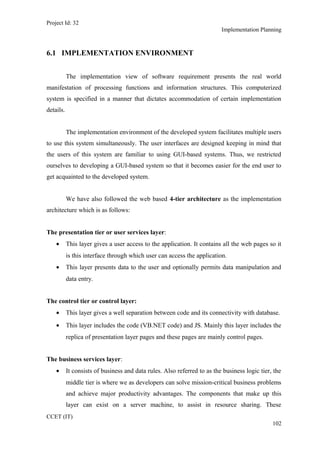
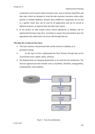
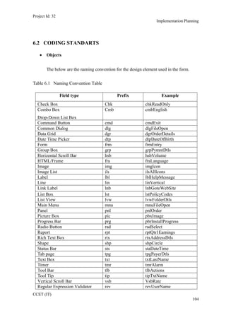
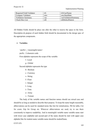
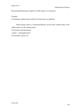


The document discusses implementation planning for Project ID 32. It describes a 4-tier architecture with presentation, control, business, and data tiers. The implementation environment supports multiple simultaneous users through a GUI-based interface. Coding standards are also defined, including naming conventions for variables, functions, and other elements that begin with a prefix to indicate scope or type followed by a meaningful name in mixed case.


![Project Management (Practical Qustion Paper) [CBSGS - 75:25 Pattern] {Manual}](https://cdn.slidesharecdn.com/ss_thumbnails/pm-cbsgs-manual-pq-190610125453-thumbnail.jpg?width=640&height=640&fit=bounds)
![Project Management (Practical Qustion Paper) [CBSGS - 75:25 Pattern] {2013-20...](https://cdn.slidesharecdn.com/ss_thumbnails/pm-cbsgs-2013-2014-manual-pq-190610125503-thumbnail.jpg?width=640&height=640&fit=bounds)