Download to read offline
![1 volt = 1 joule/I coulomb
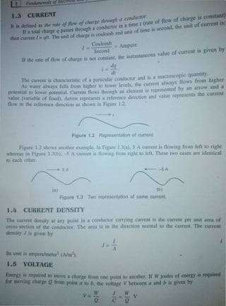
unit of voltage is volt (V).
ID Figure l.4(a), terminal A is +8 V above terminal B. In Figure l.4(b), tenninal •
terminal A or in other words +8 V below A. Also it can be written as VM •
l.4(a)] and VBA = -8 V [Figure l.4(b)] by using double subscript notation and in
AB=-VBA.
0
I
0 0
I 0
A B A B
+ 8V 8V +
(a) (b)
Figure 1:4 Two equivalent voltage representations.
ENERGY
...
To transfer a charge through an element, work is being_done. To determine the energy being
supplied to the element or by the element to the rest of the circuit, both the polarity of the
voltage across the element and the direction of the current through the el.ement must be known. If
a positive current enters the positive terminal of an element, an external force must drive_the
current. Therefore, the external force delivering energy to the element. On the other hand, if the
current leaves the positive terminal or enters the negative terminal, the element is delivering
energy to the external citcuit.
In Figures l.5(a) and l.5(b), the element is absorbing energy whereas in Figures l.5(c) and
1.5(d), the element is delivering energy.
4A
(a)
+
8V
4A
(b)
8V
+
4A
(c)
+
8V
4A
av
+
(d)
Figure 1.5 Different voltage-current relatlonshlps.
is v (say) and a small eharge Aq is m
1.-.11Vo.:](https://image.slidesharecdn.com/chapter01-200322082904/85/Chapter-01-3-320.jpg)


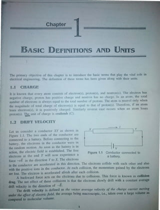
This chapter introduces basic electrical engineering terms and their units. It defines charge, current, drift velocity, current density, voltage, power, voltage drop/rise and basic circuit components. Current is defined as the rate of flow of charge through a conductor. The SI unit for current is the ampere. Current direction is indicated by an arrow and its magnitude by a number next to the arrow. Common multiples and sub-multiples of units are also presented.


