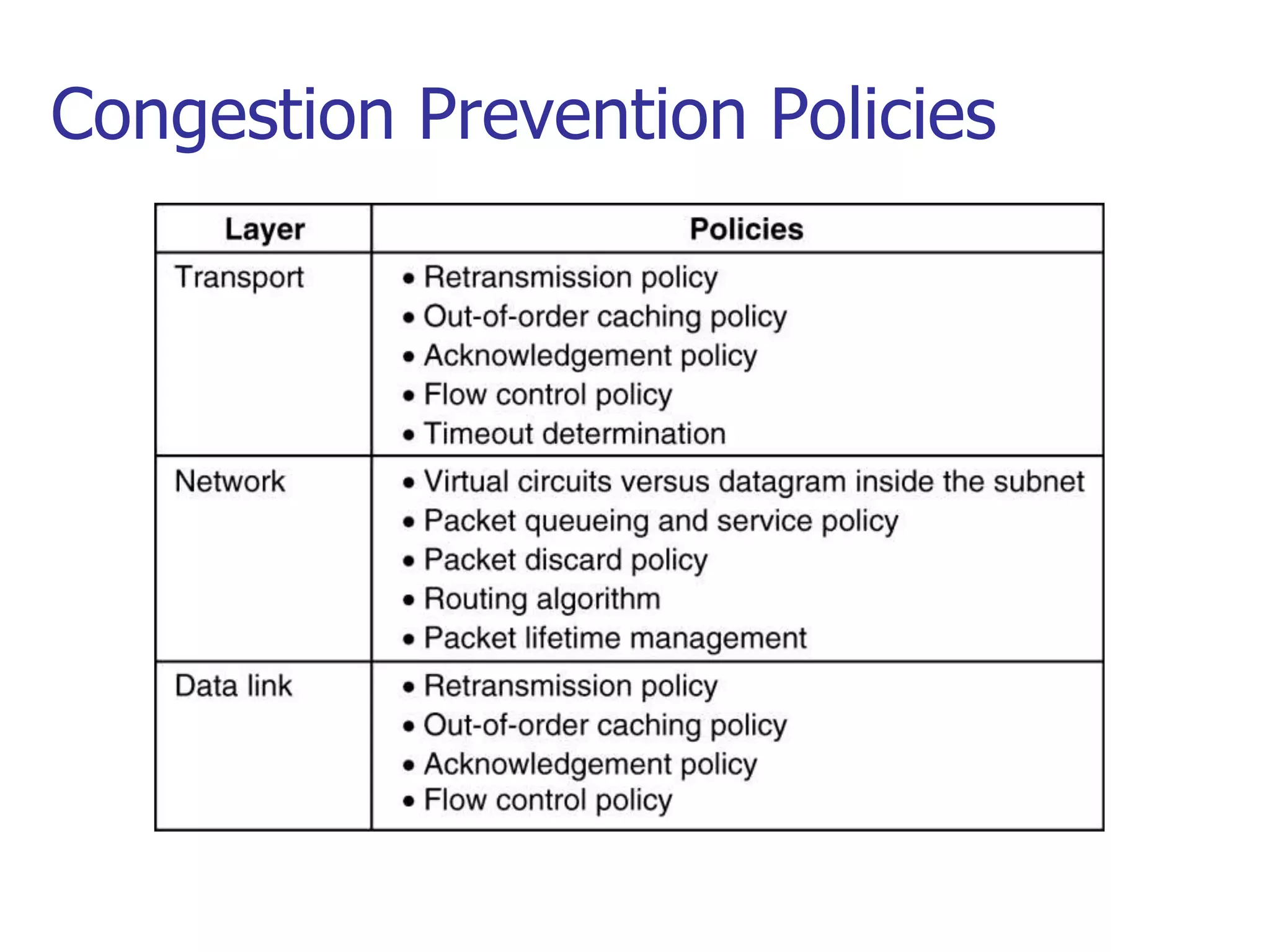
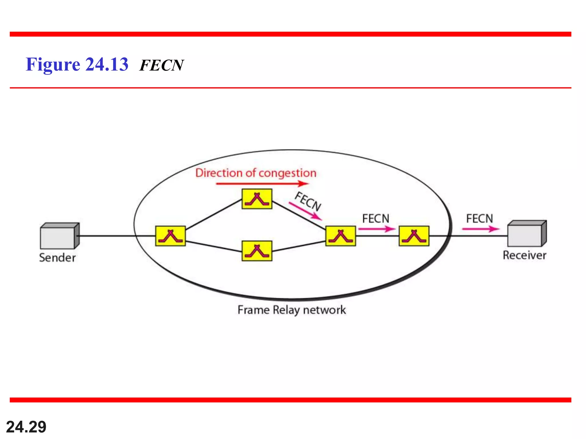
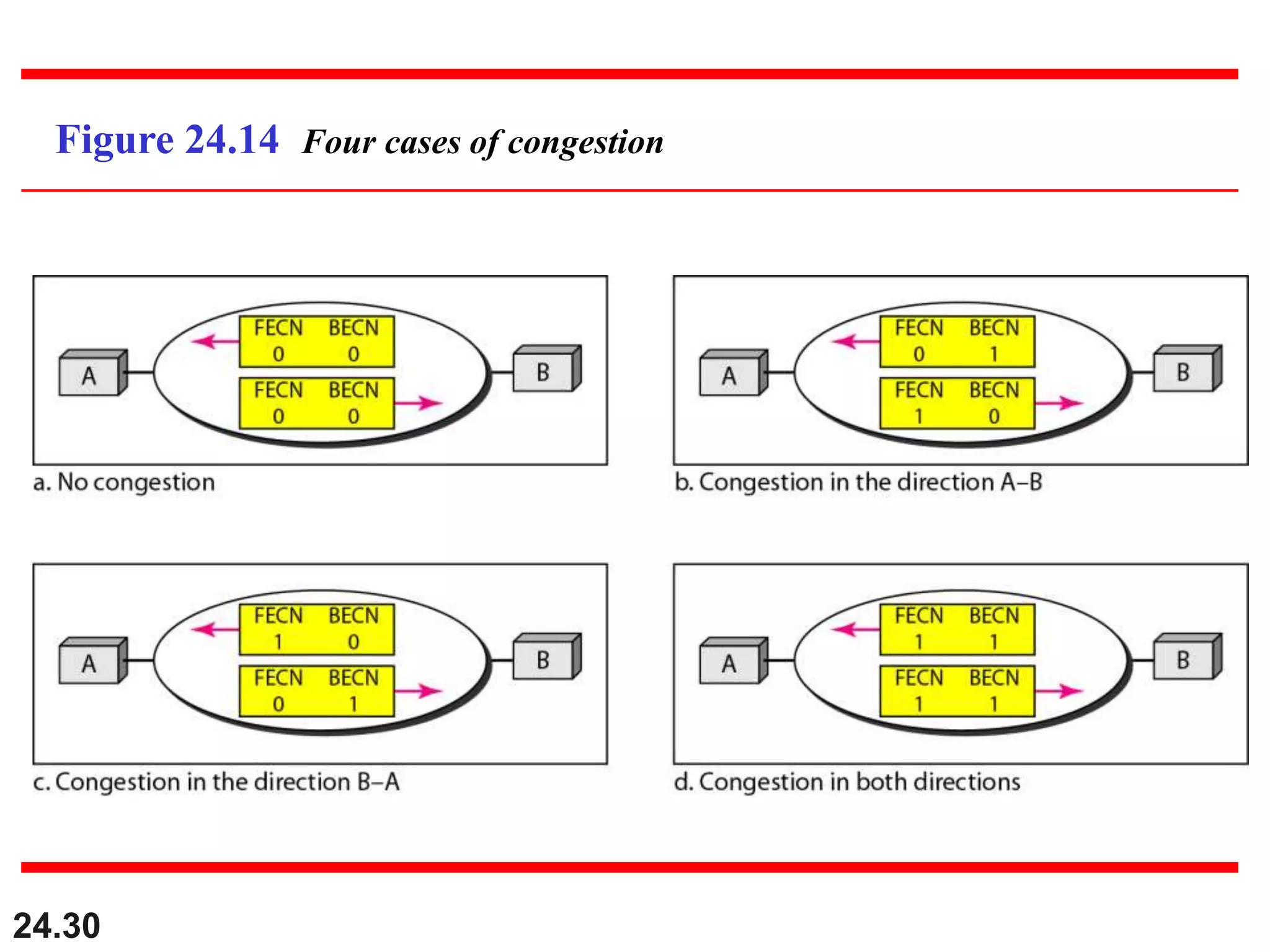
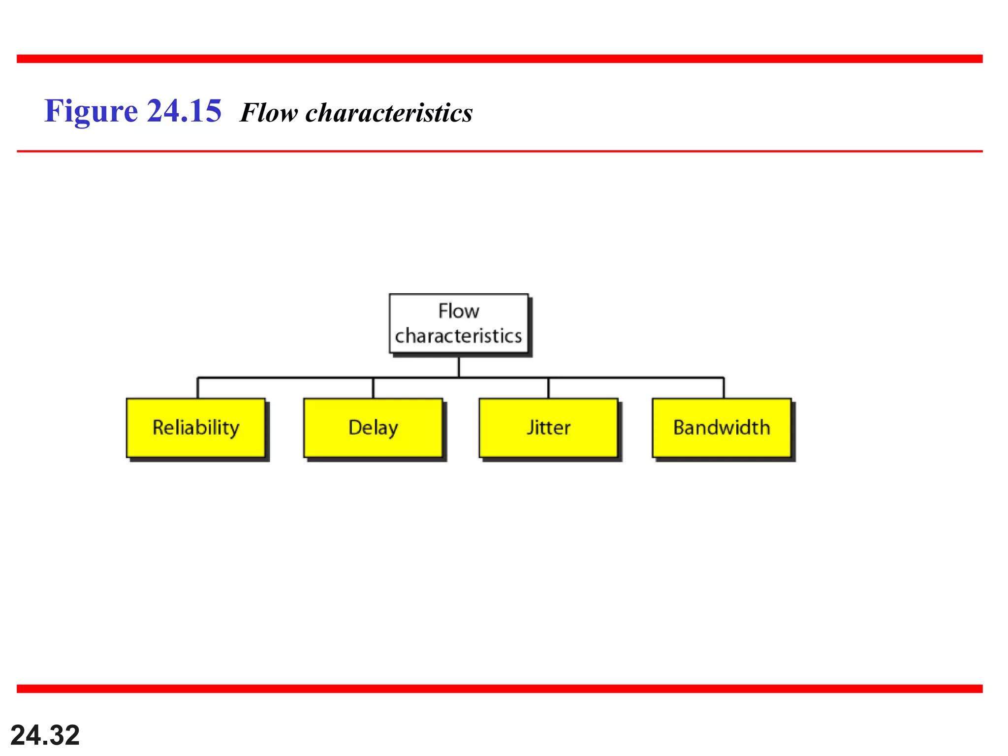
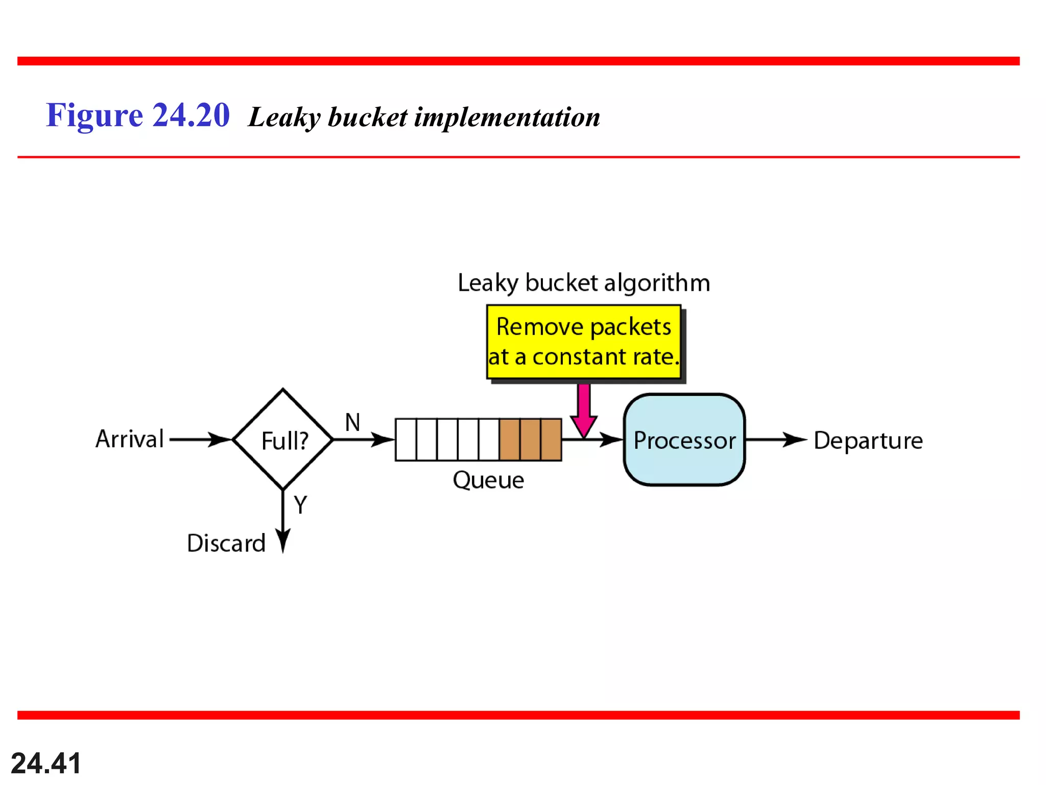
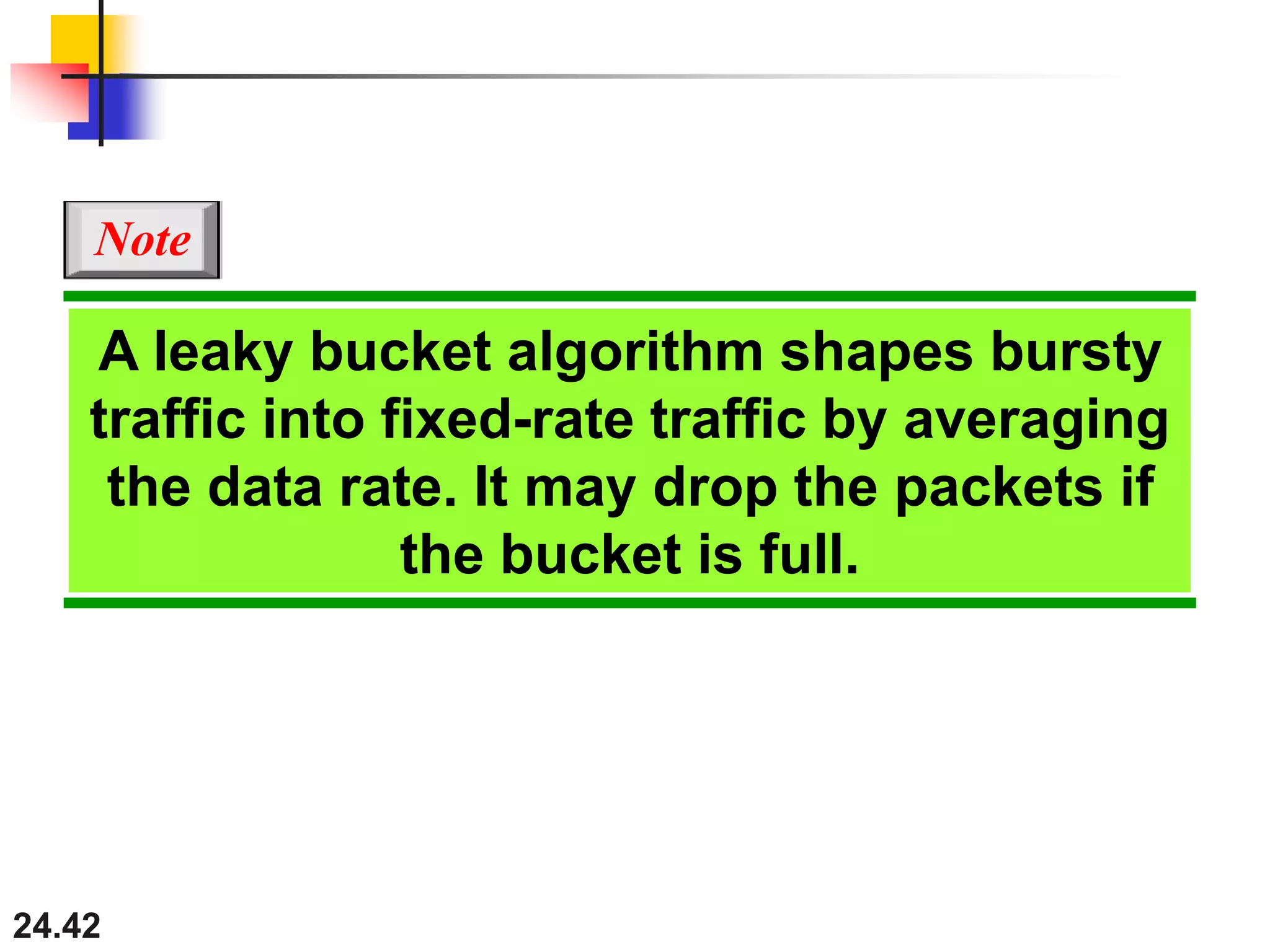
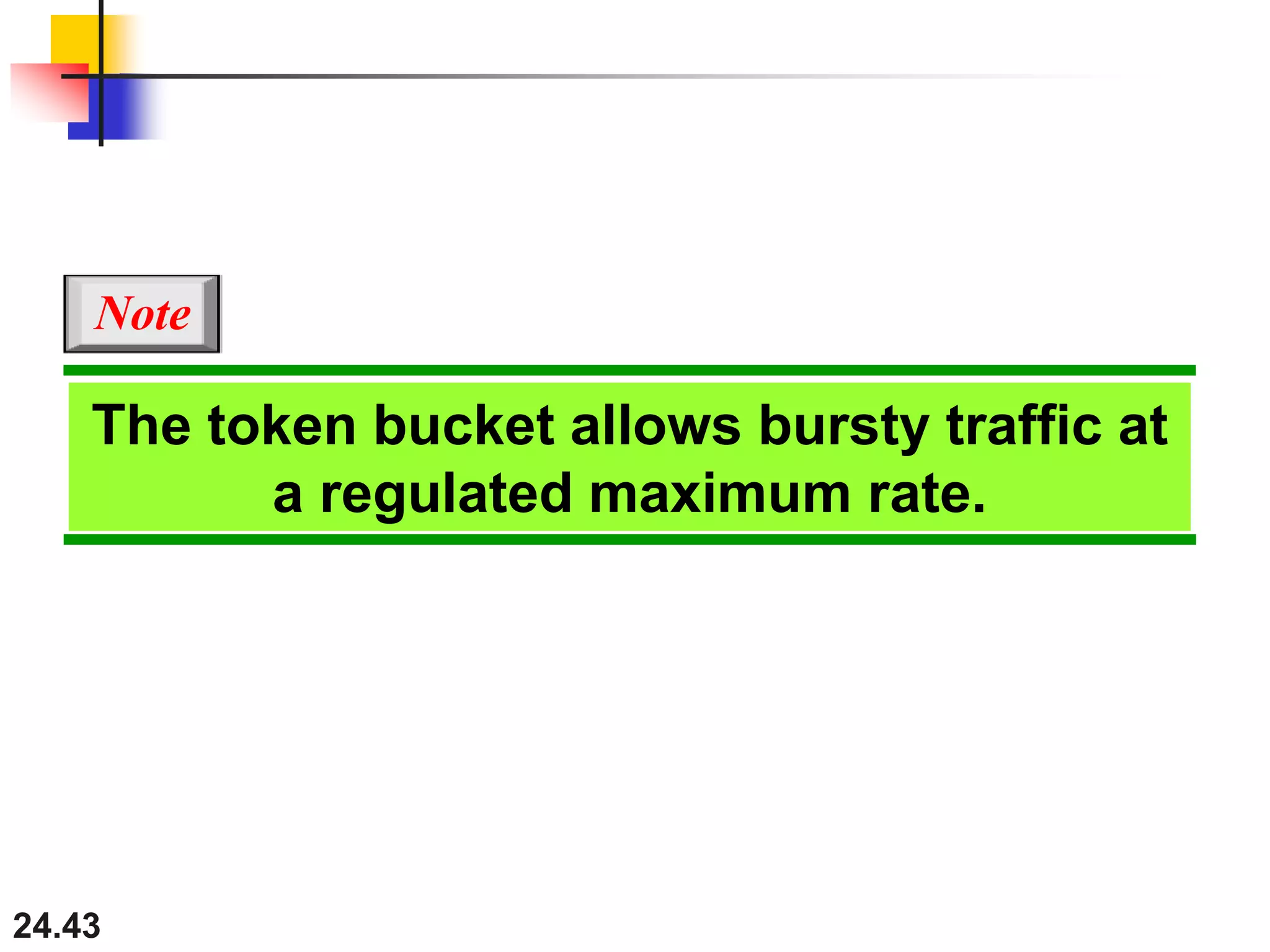
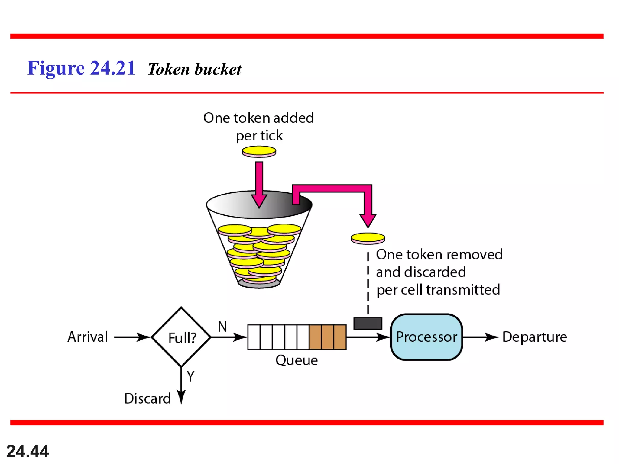
24.1
Chapter 24
Congestion Control and
Quality of Service
Copyright © The McGraw-Hill Companies, Inc. Permission required for reproduction or display.
24.2
24-1 DATA TRAFFIC
The main focus of congestion control and quality of
service is data traffic. In congestion control we try to
avoid traffic congestion. In quality of service, we try to
create an appropriate environment for the traffic. So,
before talking about congestion control and quality of
service, we discuss the data traffic itself.
Traffic Descriptor
Traffic Profiles
Topics discussed in this section:
24.3
Figure 24.1 Traffic descriptors
24.4
Figure 24.2 Three traffic profiles
24.5
24-2 CONGESTION
Congestion in a network may occur if the load on the
network—the number of packets sent to the network—
is greater than the capacity of the network—the
number of packets a network can handle. Congestion
control refers to the mechanisms and techniques to
control the congestion and keep the load below the
capacity.
Network Performance
Topics discussed in this section:
Congestion Control Introduction:
 When too many packets are present in (a part of) the subnet,
performance degrades. This situation is called congestion.
 As traffic increases too far, the routers are no longer able to cope
and they begin losing packets.
 At very high traffic, performance collapses completely and almost no
packets are delivered.
 Reasons of Congestion:
 Slow Processors.
 High stream of packets sent from one of the sender.
 Insufficient memory.
 High memory of Routers also add to congestion as becomes un
manageable and un accessible. (Nagle, 1987).
 Low bandwidth lines.
 Then what is congestion control? Congestion control has to do
with making sure the subnet is able to carry the offered traffic.
 Congestion control and flow control are often confused but both
helps reduce congestion.
General Principles of Congestion Control
 Three Step approach to apply congestion control:
1. Monitor the system .
 detect when and where congestion occurs.
2. Pass information to where action can be taken.
3. Adjust system operation to correct the problem.
 How to monitor the subnet for congestion.
1) percentage of all packets discarded for lack of buffer
space,
2) average queue lengths,
3) number of packets that time out and are retransmitted,
4) average packet delay
5) standard deviation of packet delay (jitter Control).
 Knowledge of congestion will cause the hosts to take appropriate action to reduce
the congestion.
 For a scheme to work correctly, the time scale must be adjusted carefully.
 If every time two packets arrive in a row, a router yells STOP and every time a
router is idle for 20 µsec, it yells GO, the system will oscillate wildly and never
converge.
 Dividing all algorithms into
 open loop or
 closed loop
 They further divide the open loop algorithms into ones that act at the source versus
ones that act at the destination.
 The closed loop algorithms are also divided into two subcategories:
 explicit feedback implicit feedback.
 In explicit feedback algorithms, packets are sent back from the point of
congestion to warn the source.
 In implicit algorithms, the source deduces the existence of congestion by
making local observations, such as the time needed for acknowledgements to
come back.
 The presence of congestion means that the load is (temporarily) greater than the
resources can handle.
 Solution?
 increase the resources or
 decrease the load.
 That is not always possible. So we have to apply some congestion prevention
policy.
24.9
Figure 24.3 Queues in a router
24.10
Figure Packet delay and throughput as functions of load
24.11
24-3 CONGESTION CONTROL
Congestion control refers to techniques and
mechanisms that can either prevent congestion, before
it happens, or remove congestion, after it has
happened. In general, we can divide congestion
control mechanisms into two broad categories: open-
loop congestion control (prevention) and closed-loop
congestion control (removal).
Open-Loop Congestion Control
Closed-Loop Congestion Control
Topics discussed in this section:
24.12
Figure 24.5 Congestion control categories
Warning Bit or Backpressure:
 DECNET(Digital Equipment Corporation to connect mini
computers) architecture signaled the warning state by setting
a special bit in the packet's header.
 The source then cut back on traffic.
 The source monitored the fraction of acknowledgements with
the bit set and adjusted its transmission rate accordingly.
 As long as the warning bits continued to flow in, the source
continued to decrease its transmission rate. When they
slowed to a trickle, it increased its transmission rate.
 Disadvantage: Note that since every router along the path
could set the warning bit, traffic increased only when no
router was in trouble.
24.14
Figure 24.6 Backpressure method for alleviating congestion
Choke Packets:
 The router sends a choke packet back to the source host, giving it
the destination found on the path.
 The original packet is tagged (a header bit is turned on) so that it
will not generate any more choke packets farther along the path
and is then forwarded in the usual way.
 When the source host gets the choke packet, it is required to reduce
the traffic sent to the specified destination by X percent.
 See next figure, flow starts reducing from step 5.
 Reduction from 25% to 50% to 75% and so on.
 Router maintains threshold. And based on it gives
 Mild Warning
 Stern Warning
 Ultimatum.
 Variation: Use queue length or buffers instead of line utilization as
trigger signal. This will reduce traffic. Chocks also increase traffic.
24.16
Figure 24.7 Choke packet
Congestion Prevention Policies
Policies that affect congestion.
5-26
 Systems are designed to minimize congestion in the
first place, rather than letting it happen and reacting
after the fact.
1. Data Link Layer:
 The retransmission policy is concerned with how fast a
sender times out and retransmits. A jumpy sender that
times out quickly and retransmits all outstanding packets
using go back n will put a heavier load on the system than
will a leisurely sender that uses selective repeat.
 Out of order packets management depends upon buffering
policy. If receivers routinely discard all out-of-order
packets, these packets will have to be transmitted again
later, creating extra load i.e prefer selective repeat instead
of GoBackN.
 Acknowledgement packets generate extra traffic. Solution?
Piggyback.
 Flow Control: Tight Flow and Loose Flow. Tight flow
means smaller windows protocols, reduces data rate, helps
fight congestion.
2. Network Layer:
 choice between using virtual circuits and using datagram's
affects congestion since many congestion control
algorithms work only with virtual-circuit subnets.
 Packet queuing and service policy relates to whether
routers have one queue per input line, one queue per
output line, or both. round robin or priority based?
 Discard policy is the rule telling which packet is dropped
when there is no space.
 Routing policy we have already discussed a lot upon.
 Packet lifetime management deals with how long a packet
may live before being discarded.
3. Transport Layer:
 Same issues occur as in the data link layer
 If the timeout interval is too short, extra packets will be
sent unnecessarily. If it is too long, congestion will be
reduced but the response time will suffer whenever a
packet is lost.
24.20
24-4 TWO EXAMPLES
To better understand the concept of congestion
control, let us give two examples: one in TCP and the
other in Frame Relay.
Congestion Control in TCP
Congestion Control in Frame Relay
Topics discussed in this section:
24.21
Figure 24.8 Slow start, exponential increase
24.22
In the slow-start algorithm, the size of
the congestion window increases
exponentially until it reaches a
threshold.
Note
24.23
Figure 24.9 Congestion avoidance, additive increase
24.24
In the congestion avoidance algorithm,
the size of the congestion window
increases additively until
congestion is detected.
Note
24.25
An implementation reacts to congestion
detection in one of the following ways:
❏ If detection is by time-out, a new slow
start phase starts.
❏ If detection is by three ACKs, a new
congestion avoidance phase starts.
Note
24.26
Figure 24.10 TCP congestion policy summary
24.27
Figure 24.11 Congestion example
24.28
Figure 24.12 BECN
24.29
Figure 24.13 FECN
24.30
Figure 24.14 Four cases of congestion
24.31
24-5 QUALITY OF SERVICE
Quality of service (QoS) is an internetworking issue
that has been discussed more than defined. We can
informally define quality of service as something a
flow seeks to attain.
Flow Characteristics
Flow Classes
Topics discussed in this section:
24.32
Figure 24.15 Flow characteristics
24.33
24-6 TECHNIQUES TO IMPROVE QoS
In Section 24.5 we tried to define QoS in terms of its
characteristics. In this section, we discuss some
techniques that can be used to improve the quality of
service. We briefly discuss four common methods:
scheduling, traffic shaping, admission control, and
resource reservation.
Scheduling
Traffic Shaping
Resource Reservation
Admission Control
Topics discussed in this section:
Scheduling
Scheduling
FIFO
Priority
Queue
Weighted
Fair Queue
RED
24.34
24.35
Figure 24.16 FIFO queue
24.36
Figure 24.17 Priority queuing
24.37
Figure 24.18 Weighted fair queuing
Random Early Detection:
 It is the idea of discarding packets before all the buffer space is really
exhausted.
 A popular algorithm for doing this is called RED (Random Early
Detection) (Floyd and Jacobson, 1993).
 Response to lost packets is the source to slow down.
 Lost packets are mostly due to buffer overruns rather than
transmission errors.
 The idea is that there is time for action to be taken before it is too
late.
 To determine when to start discarding? For this, routers maintain a
running average of their queue lengths.
 When the average queue length on some line exceeds a threshold,
the line is said to be congested and action is taken.
 How should the router tell the source about the problem?
 One way is to send it a choke packet.
 Other option? Just discard the selected packet and don’t report even.
 Source will eventually notice lack of Ack and takes action.
 Thus, slowing down instead of trying harder.
Traffic Shaping
Traffic
Shaping
Leaky
Bucket
Token
Bucket
24.39
24.40
Figure 24.19 Leaky bucket
24.41
Figure 24.20 Leaky bucket implementation
24.42
A leaky bucket algorithm shapes bursty
traffic into fixed-rate traffic by averaging
the data rate. It may drop the packets if
the bucket is full.
Note
24.43
The token bucket allows bursty traffic at
a regulated maximum rate.
Note
24.44
Figure 24.21 Token bucket
Resource Reservation and
Admission Control
 Buffer, CPU Time, Bandwidth are the
resources that can be reserved for
particular flows for particular time to
maintain the QoS.
 Mechanism used by routers to accept or
reject flows based on flow specifications is
what we call Admission Control.
24.45

ch24-congestion-control-and-quality-of-service.ppt

  • 1.
    24.1 Chapter 24 Congestion Controland Quality of Service Copyright © The McGraw-Hill Companies, Inc. Permission required for reproduction or display.
  • 2.
    24.2 24-1 DATA TRAFFIC Themain focus of congestion control and quality of service is data traffic. In congestion control we try to avoid traffic congestion. In quality of service, we try to create an appropriate environment for the traffic. So, before talking about congestion control and quality of service, we discuss the data traffic itself. Traffic Descriptor Traffic Profiles Topics discussed in this section:
  • 3.
  • 4.
    24.4 Figure 24.2 Threetraffic profiles
  • 5.
    24.5 24-2 CONGESTION Congestion ina network may occur if the load on the network—the number of packets sent to the network— is greater than the capacity of the network—the number of packets a network can handle. Congestion control refers to the mechanisms and techniques to control the congestion and keep the load below the capacity. Network Performance Topics discussed in this section:
  • 6.
    Congestion Control Introduction: When too many packets are present in (a part of) the subnet, performance degrades. This situation is called congestion.  As traffic increases too far, the routers are no longer able to cope and they begin losing packets.  At very high traffic, performance collapses completely and almost no packets are delivered.  Reasons of Congestion:  Slow Processors.  High stream of packets sent from one of the sender.  Insufficient memory.  High memory of Routers also add to congestion as becomes un manageable and un accessible. (Nagle, 1987).  Low bandwidth lines.  Then what is congestion control? Congestion control has to do with making sure the subnet is able to carry the offered traffic.  Congestion control and flow control are often confused but both helps reduce congestion.
  • 7.
    General Principles ofCongestion Control  Three Step approach to apply congestion control: 1. Monitor the system .  detect when and where congestion occurs. 2. Pass information to where action can be taken. 3. Adjust system operation to correct the problem.  How to monitor the subnet for congestion. 1) percentage of all packets discarded for lack of buffer space, 2) average queue lengths, 3) number of packets that time out and are retransmitted, 4) average packet delay 5) standard deviation of packet delay (jitter Control).
  • 8.
     Knowledge ofcongestion will cause the hosts to take appropriate action to reduce the congestion.  For a scheme to work correctly, the time scale must be adjusted carefully.  If every time two packets arrive in a row, a router yells STOP and every time a router is idle for 20 µsec, it yells GO, the system will oscillate wildly and never converge.  Dividing all algorithms into  open loop or  closed loop  They further divide the open loop algorithms into ones that act at the source versus ones that act at the destination.  The closed loop algorithms are also divided into two subcategories:  explicit feedback implicit feedback.  In explicit feedback algorithms, packets are sent back from the point of congestion to warn the source.  In implicit algorithms, the source deduces the existence of congestion by making local observations, such as the time needed for acknowledgements to come back.  The presence of congestion means that the load is (temporarily) greater than the resources can handle.  Solution?  increase the resources or  decrease the load.  That is not always possible. So we have to apply some congestion prevention policy.
  • 9.
  • 10.
    24.10 Figure Packet delayand throughput as functions of load
  • 11.
    24.11 24-3 CONGESTION CONTROL Congestioncontrol refers to techniques and mechanisms that can either prevent congestion, before it happens, or remove congestion, after it has happened. In general, we can divide congestion control mechanisms into two broad categories: open- loop congestion control (prevention) and closed-loop congestion control (removal). Open-Loop Congestion Control Closed-Loop Congestion Control Topics discussed in this section:
  • 12.
    24.12 Figure 24.5 Congestioncontrol categories
  • 13.
    Warning Bit orBackpressure:  DECNET(Digital Equipment Corporation to connect mini computers) architecture signaled the warning state by setting a special bit in the packet's header.  The source then cut back on traffic.  The source monitored the fraction of acknowledgements with the bit set and adjusted its transmission rate accordingly.  As long as the warning bits continued to flow in, the source continued to decrease its transmission rate. When they slowed to a trickle, it increased its transmission rate.  Disadvantage: Note that since every router along the path could set the warning bit, traffic increased only when no router was in trouble.
  • 14.
    24.14 Figure 24.6 Backpressuremethod for alleviating congestion
  • 15.
    Choke Packets:  Therouter sends a choke packet back to the source host, giving it the destination found on the path.  The original packet is tagged (a header bit is turned on) so that it will not generate any more choke packets farther along the path and is then forwarded in the usual way.  When the source host gets the choke packet, it is required to reduce the traffic sent to the specified destination by X percent.  See next figure, flow starts reducing from step 5.  Reduction from 25% to 50% to 75% and so on.  Router maintains threshold. And based on it gives  Mild Warning  Stern Warning  Ultimatum.  Variation: Use queue length or buffers instead of line utilization as trigger signal. This will reduce traffic. Chocks also increase traffic.
  • 16.
  • 17.
    Congestion Prevention Policies Policiesthat affect congestion. 5-26
  • 18.
     Systems aredesigned to minimize congestion in the first place, rather than letting it happen and reacting after the fact. 1. Data Link Layer:  The retransmission policy is concerned with how fast a sender times out and retransmits. A jumpy sender that times out quickly and retransmits all outstanding packets using go back n will put a heavier load on the system than will a leisurely sender that uses selective repeat.  Out of order packets management depends upon buffering policy. If receivers routinely discard all out-of-order packets, these packets will have to be transmitted again later, creating extra load i.e prefer selective repeat instead of GoBackN.  Acknowledgement packets generate extra traffic. Solution? Piggyback.  Flow Control: Tight Flow and Loose Flow. Tight flow means smaller windows protocols, reduces data rate, helps fight congestion.
  • 19.
    2. Network Layer: choice between using virtual circuits and using datagram's affects congestion since many congestion control algorithms work only with virtual-circuit subnets.  Packet queuing and service policy relates to whether routers have one queue per input line, one queue per output line, or both. round robin or priority based?  Discard policy is the rule telling which packet is dropped when there is no space.  Routing policy we have already discussed a lot upon.  Packet lifetime management deals with how long a packet may live before being discarded. 3. Transport Layer:  Same issues occur as in the data link layer  If the timeout interval is too short, extra packets will be sent unnecessarily. If it is too long, congestion will be reduced but the response time will suffer whenever a packet is lost.
  • 20.
    24.20 24-4 TWO EXAMPLES Tobetter understand the concept of congestion control, let us give two examples: one in TCP and the other in Frame Relay. Congestion Control in TCP Congestion Control in Frame Relay Topics discussed in this section:
  • 21.
    24.21 Figure 24.8 Slowstart, exponential increase
  • 22.
    24.22 In the slow-startalgorithm, the size of the congestion window increases exponentially until it reaches a threshold. Note
  • 23.
    24.23 Figure 24.9 Congestionavoidance, additive increase
  • 24.
    24.24 In the congestionavoidance algorithm, the size of the congestion window increases additively until congestion is detected. Note
  • 25.
    24.25 An implementation reactsto congestion detection in one of the following ways: ❏ If detection is by time-out, a new slow start phase starts. ❏ If detection is by three ACKs, a new congestion avoidance phase starts. Note
  • 26.
    24.26 Figure 24.10 TCPcongestion policy summary
  • 27.
  • 28.
  • 29.
  • 30.
    24.30 Figure 24.14 Fourcases of congestion
  • 31.
    24.31 24-5 QUALITY OFSERVICE Quality of service (QoS) is an internetworking issue that has been discussed more than defined. We can informally define quality of service as something a flow seeks to attain. Flow Characteristics Flow Classes Topics discussed in this section:
  • 32.
    24.32 Figure 24.15 Flowcharacteristics
  • 33.
    24.33 24-6 TECHNIQUES TOIMPROVE QoS In Section 24.5 we tried to define QoS in terms of its characteristics. In this section, we discuss some techniques that can be used to improve the quality of service. We briefly discuss four common methods: scheduling, traffic shaping, admission control, and resource reservation. Scheduling Traffic Shaping Resource Reservation Admission Control Topics discussed in this section:
  • 34.
  • 35.
  • 36.
  • 37.
  • 38.
    Random Early Detection: It is the idea of discarding packets before all the buffer space is really exhausted.  A popular algorithm for doing this is called RED (Random Early Detection) (Floyd and Jacobson, 1993).  Response to lost packets is the source to slow down.  Lost packets are mostly due to buffer overruns rather than transmission errors.  The idea is that there is time for action to be taken before it is too late.  To determine when to start discarding? For this, routers maintain a running average of their queue lengths.  When the average queue length on some line exceeds a threshold, the line is said to be congested and action is taken.  How should the router tell the source about the problem?  One way is to send it a choke packet.  Other option? Just discard the selected packet and don’t report even.  Source will eventually notice lack of Ack and takes action.  Thus, slowing down instead of trying harder.
  • 39.
  • 40.
  • 41.
    24.41 Figure 24.20 Leakybucket implementation
  • 42.
    24.42 A leaky bucketalgorithm shapes bursty traffic into fixed-rate traffic by averaging the data rate. It may drop the packets if the bucket is full. Note
  • 43.
    24.43 The token bucketallows bursty traffic at a regulated maximum rate. Note
  • 44.
  • 45.
    Resource Reservation and AdmissionControl  Buffer, CPU Time, Bandwidth are the resources that can be reserved for particular flows for particular time to maintain the QoS.  Mechanism used by routers to accept or reject flows based on flow specifications is what we call Admission Control. 24.45