2.2
2-1 LAYERED TASKS
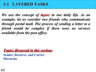
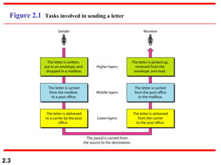
2-1LAYERED TASKS
We use the concept of
We use the concept of layers
layers in our daily life. As an
in our daily life. As an
example, let us consider two friends who communicate
example, let us consider two friends who communicate
through postal mail. The process of sending a letter to a
through postal mail. The process of sending a letter to a
friend would be complex if there were no services
friend would be complex if there were no services
available from the post office.
available from the post office.
Sender, Receiver, and Carrier
Hierarchy
Topics discussed in this section:
Topics discussed in this section:
2.4
2-2 THE OSIMODEL
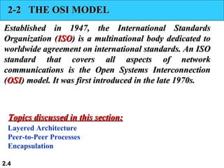
2-2 THE OSI MODEL
Established in 1947, the International Standards
Established in 1947, the International Standards
Organization (
Organization (ISO
ISO) is a multinational body dedicated to
) is a multinational body dedicated to
worldwide agreement on international standards. An ISO
worldwide agreement on international standards. An ISO
standard that covers all aspects of network
standard that covers all aspects of network
communications is the Open Systems Interconnection
communications is the Open Systems Interconnection
(
(OSI
OSI) model. It was first introduced in the late 1970s.
) model. It was first introduced in the late 1970s.
Layered Architecture
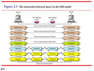
Peer-to-Peer Processes
Encapsulation
Topics discussed in this section:
Topics discussed in this section:
2.8
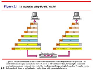
Figure 2.4 Anexchange using the OSI model
A packet consists of two kinds of data: control information and user data (also known as payload). The
control information provides data the network needs to deliver the user data, for example: source and
destination addresses, error detection codes like checksums, and sequencing information. Typically, control
information is found in packet headers and trailers, with user data in between.
9.
2.9
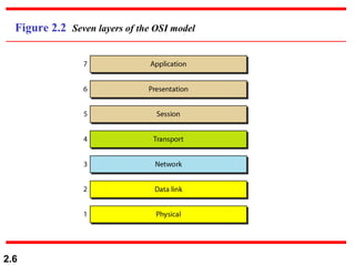
2-3 LAYERS INTHE OSI MODEL
2-3 LAYERS IN THE OSI MODEL
In this section we briefly describe the functions of each
In this section we briefly describe the functions of each
layer in the OSI model.
layer in the OSI model.
Physical Layer
Data Link Layer
Network Layer
Transport Layer
Session Layer
Presentation Layer
Application Layer
Topics discussed in this section:
Topics discussed in this section:
10.
2.10
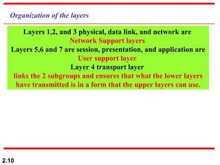
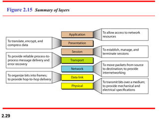
Organization of thelayers
Layers 1,2, and 3 physical, data link, and network are
Network Support layers
Layers 5,6 and 7 are session, presentation, and application are
User support layer
Layer 4 transport layer
links the 2 subgroups and ensures that what the lower layers
have transmitted is in a form that the upper layers can use.
11.
2.11
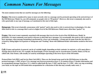
Common Names ForMessages
The most common terms that are used for messages are the following:
Packet: This term is considered by many to most correctly refer to a message sent by protocols operating at the network layer of
the OSI Reference Model. So, you will commonly see people refer to “IP packets”. However, this term is commonly also used to
refer generically to any type of message, as I mentioned at the start of this topic.
Datagram: This term is basically synonymous with “packet” and is also used to refer to network layer technologies. It is also
often used to refer to a message that is sent at a higher level of the OSI Reference Model (more often than “packet” is).
Frame: This term is most commonly associated with messages that travel at low levels of the OSI Reference Model. In
particular, it is most commonly seen used in reference to data link layer messages. It is occasionally also used to refer to physical
layer messages, when message formatting is performed by a layer one technology. A frame gets its name from the fact that it is
created by taking higher-level packets or datagrams and “framing” them with additional header information needed at the lower
level.
Cell: Frames and packets, in general, can be of variable length, depending on their contents; in contrast, a cell is most often a
message that is fixed in size. For example, the fixed-length, 53-byte messages sent in Asynchronous Transfer Mode (ATM) are
called cells. Like frames, cells usually are used by technologies operating at the lower layers of the OSI model.
Protocol Data Unit (PDU) and Service Data Unit (SDU): These are the formal terms used in the OSI Reference to describe
protocol messages. A PDU at layer N is a message sent between protocols at layer N. It consists of layer N header information and
an encapsulated message from layer N+1, which is called both the layer N SDU and the layer N+1 PDU. After you stop scratching
your head, see the topic on OSI model data encapsulation for a discussion of this that may actually make sense. J
12.
2.12
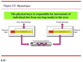
Figure 2.5 Physicallayer
The physical layer is responsible for movements of
individual bits from one hop (node) to the next.
13.
2.13
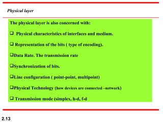
Physical layer
The physicallayer is also concerned with:
Physical characteristics of interfaces and medium.
Representation of the bits ( type of encoding).
Data Rate. The transmission rate
Synchronization of bits.
Line configuration ( point-point, multipoint)
Physical Technology (how devices are connected –network)
Transmission mode (simplex, h-d, f-d
14.
2.14
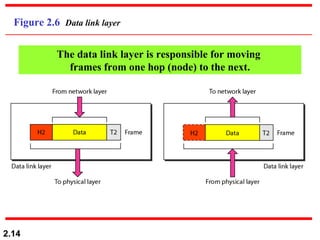
Figure 2.6 Datalink layer
The data link layer is responsible for moving
frames from one hop (node) to the next.
15.
2.15
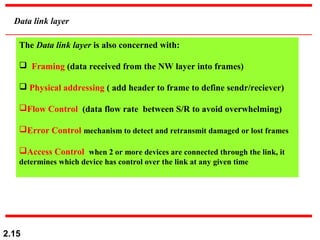
Data link layer
TheData link layer is also concerned with:
Framing (data received from the NW layer into frames)
Physical addressing ( add header to frame to define sendr/reciever)
Flow Control (data flow rate between S/R to avoid overwhelming)
Error Control mechanism to detect and retransmit damaged or lost frames
Access Control when 2 or more devices are connected through the link, it
determines which device has control over the link at any given time
2.19
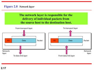
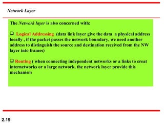
Network Layer
The Networklayer is also concerned with:
Logical Addressing (data link layer give the data a physical address
locally , if the packet passes the network boundary, we need another
address to distinguish the source and destination received from the NW
layer into frames)
Routing ( when connecting independent networks or a links to creat
internetworks or a large network, the network layer provide this
mechanism
20.
2.20
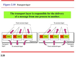
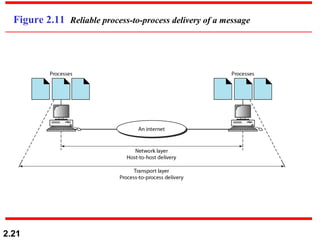
Figure 2.10 Transportlayer
The transport layer is responsible for the delivery
of a message from one process to another.
2.22
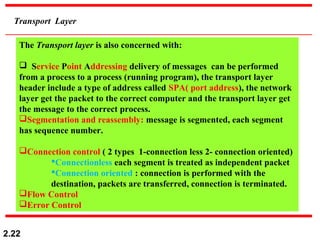
Transport Layer
The Transportlayer is also concerned with:
Service Point Addressing delivery of messages can be performed
from a process to a process (running program), the transport layer
header include a type of address called SPA( port address), the network
layer get the packet to the correct computer and the transport layer get
the message to the correct process.
Segmentation and reassembly: message is segmented, each segment
has sequence number.
Connection control ( 2 types 1-connection less 2- connection oriented)
Connectionless each segment is treated as independent packet
Connection oriented : connection is performed with the
destination, packets are transferred, connection is terminated.
Flow Control
Error Control
23.
2.23
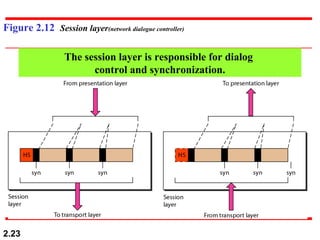
Figure 2.12 Sessionlayer(network dialogue controller)
The session layer is responsible for dialog
control and synchronization.
24.
2.24
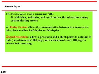
Session Layer
The Sessionlayer is also concerned with:
It establishes, maintains, and synchronizes, the interaction among
communicating system
Dialog Control allows the communication between two processes to
take place in either half-duplex or full-duplex.
Synchronization : allows a process to add a check points to a stream of
data ( a system sends 2000 page, put a check point every 100 page to
ensure their receiving).
25.
2.25
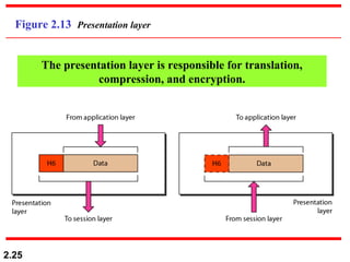
Figure 2.13 Presentationlayer
The presentation layer is responsible for translation,
compression, and encryption.
26.
2.26
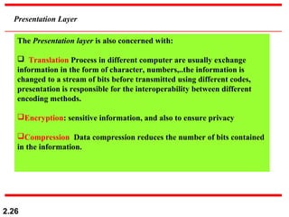
Presentation Layer
The Presentationlayer is also concerned with:
Translation Process in different computer are usually exchange
information in the form of character, numbers,..the information is
changed to a stream of bits before transmitted using different codes,
presentation is responsible for the interoperability between different
encoding methods.
Encryption: sensitive information, and also to ensure privacy
Compression Data compression reduces the number of bits contained
in the information.
2.28
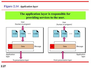
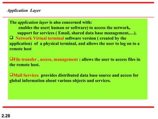
Application Layer
The applicationlayer is also concerned with:
enables the user( human or software) to access the network,
support for services ( Email, shared data base management,…).
Network Virtual terminal software version ( created by the
application) of a physical terminal, and allows the user to log on to a
remote host
File transfer , access, management : allows the user to access files in
the remote host.
Mail Services provides distributed data base source and access for
global information about various objects and services.
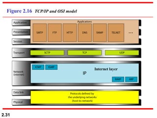
2.30
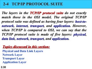
2-4 TCP/IP PROTOCOLSUITE
2-4 TCP/IP PROTOCOL SUITE
The layers in the
The layers in the TCP/IP protocol suite
TCP/IP protocol suite do not exactly
do not exactly
match those in the OSI model. The original TCP/IP
match those in the OSI model. The original TCP/IP
protocol suite was defined as having four layers:
protocol suite was defined as having four layers: host-to-
host-to-
network
network,
, internet
internet,
, transport
transport, and
, and application
application. However,
. However,
when TCP/IP is compared to OSI, we can say that the
when TCP/IP is compared to OSI, we can say that the
TCP/IP protocol suite is made of five layers:
TCP/IP protocol suite is made of five layers: physical
physical,
,
data link
data link,
, network
network,
, transport
transport, and
, and application
application.
.
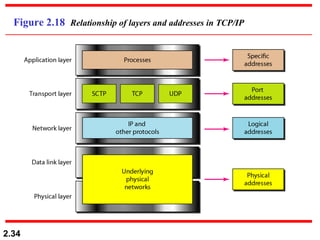
Physical and Data Link Layers
Network Layer
Transport Layer
Application Layer
Topics discussed in this section:
Topics discussed in this section:
2.32
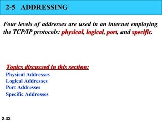
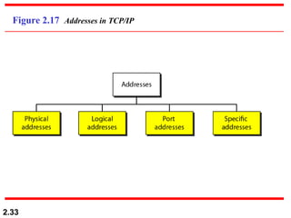
2-5 ADDRESSING
2-5 ADDRESSING
Fourlevels of addresses are used in an internet employing
Four levels of addresses are used in an internet employing
the TCP/IP protocols:
the TCP/IP protocols: physical
physical,
, logical
logical,
, port
port, and
, and specific
specific.
.
Physical Addresses
Logical Addresses
Port Addresses
Specific Addresses
Topics discussed in this section:
Topics discussed in this section:
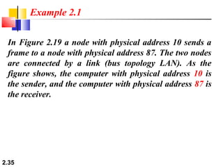
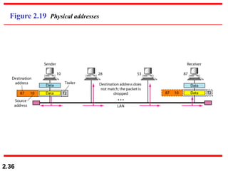
2.35
In Figure 2.19a node with physical address 10 sends a
frame to a node with physical address 87. The two nodes
are connected by a link (bus topology LAN). As the
figure shows, the computer with physical address 10 is
the sender, and the computer with physical address 87 is
the receiver.
Example 2.1
2.37
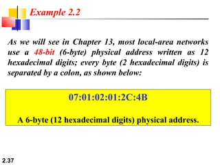
As we willsee in Chapter 13, most local-area networks
use a 48-bit (6-byte) physical address written as 12
hexadecimal digits; every byte (2 hexadecimal digits) is
separated by a colon, as shown below:
Example 2.2
07:01:02:01:2C:4B
A 6-byte (12 hexadecimal digits) physical address.
38.
2.38
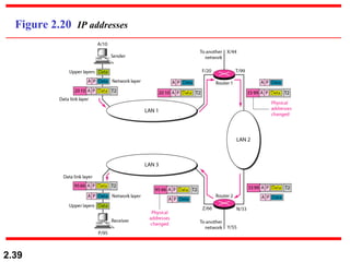
Figure 2.20 showsa part of an internet with two routers
connecting three LANs. Each device (computer or
router) has a pair of addresses (logical and physical) for
each connection. In this case, each computer is
connected to only one link and therefore has only one
pair of addresses. Each router, however, is connected to
three networks (only two are shown in the figure). So
each router has three pairs of addresses, one for each
connection.
Example 2.3
2.40
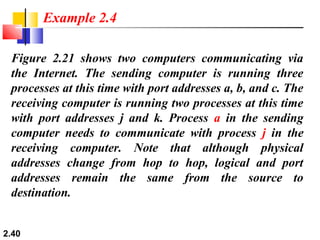
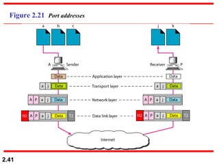
Figure 2.21 showstwo computers communicating via
the Internet. The sending computer is running three
processes at this time with port addresses a, b, and c. The
receiving computer is running two processes at this time
with port addresses j and k. Process a in the sending
computer needs to communicate with process j in the
receiving computer. Note that although physical
addresses change from hop to hop, logical and port
addresses remain the same from the source to
destination.
Example 2.4
2.42
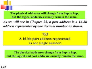
The physical addresseswill change from hop to hop,
but the logical addresses usually remain the same.
As we will see in Chapter 23, a port address is a 16-bit
address represented by one decimal number as shown.
753
A 16-bit port address represented
as one single number.
The physical addresses change from hop to hop,
but the logical and port addresses usually remain the same.