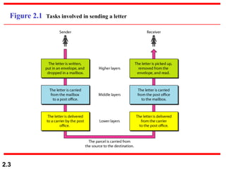
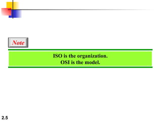
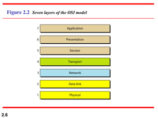
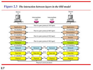
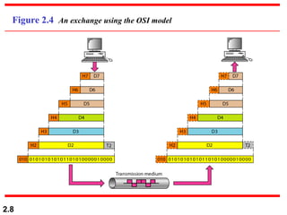
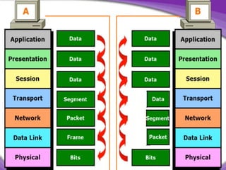
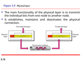
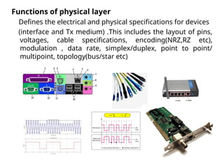
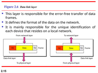
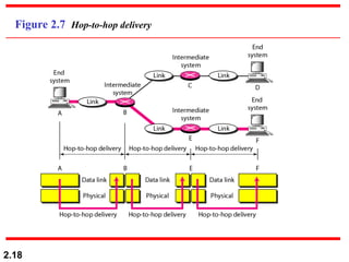
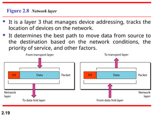
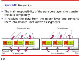
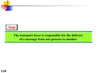
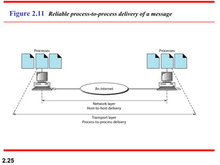
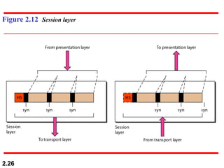
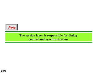
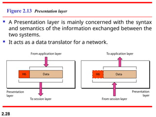
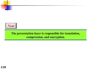
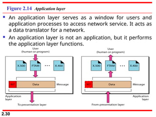
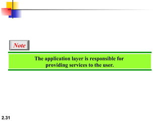
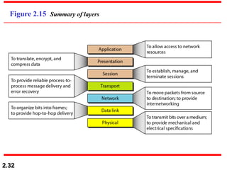
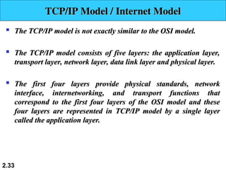
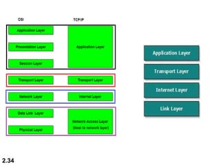
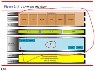
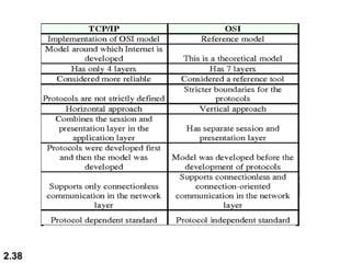
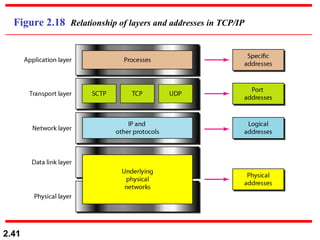
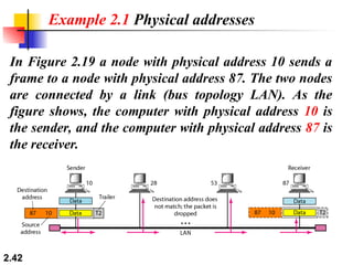
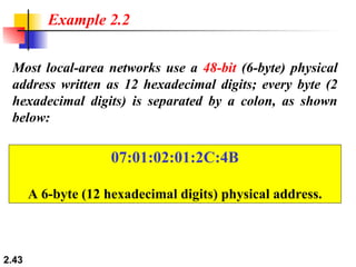
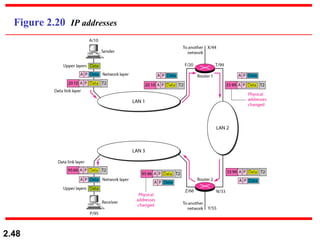
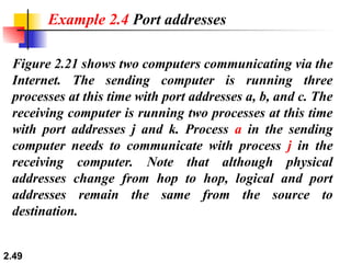
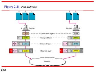
2.1
Chapter 2
Network Models
2.2
2-1 LAYERED TASKS
2-1 LAYERED TASKS
We use the concept of
We use the concept of layers
layers in our daily life. As an
in our daily life. As an
example, let us consider two friends who communicate
through postal mail. The process of sending a letter to a
friend would be complex if there were no services
available from the post office.
Sender, Receiver, and Carrier
Hierarchy
Topics discussed in this section:
2.3
Figure 2.1 Tasks involved in sending a letter
2.4
2-2 THE OSI MODEL
2-2 THE OSI MODEL
Established in 1947, the International Standards
Organization (
Organization (ISO
ISO) is a multinational body dedicated to
) is a multinational body dedicated to
worldwide agreement on international standards. An ISO
standard that covers all aspects of network
communications is the Open Systems Interconnection
(
(OSI
OSI) model. It was first introduced in the late 1970s.
) model. It was first introduced in the late 1970s.
Layered Architecture
Peer-to-Peer Processes
Encapsulation
Topics discussed in this section:
2.5
ISO is the organization.
OSI is the model.
Note
2.6
Figure 2.2 Seven layers of the OSI model
2.7
Figure 2.3 The interaction between layers in the OSI model
2.8
Figure 2.4 An exchange using the OSI model
2.9
 Application Layer:
Application Layer: This layer is responsible for providing
This layer is responsible for providing
interface to the application user. This layer encompasses
protocols which directly interact with the user.

Presentation Layer:
Presentation Layer: This layer defines how data in the
This layer defines how data in the
native format of remote host should be presented in the
native format of host.
2.10
2-3 LAYERS IN THE OSI MODEL
In this section we briefly describe the functions of each
layer in the OSI model.
 Session Layer:
Session Layer: This layer maintains sessions between
This layer maintains sessions between
remote hosts. For example, once user/password
authentication is done, the remote host maintains this
session for a while and does not ask for authentication
again in that time span.

Transport Layer
Transport Layer: This layer is responsible for end-to-end
: This layer is responsible for end-to-end
delivery between hosts.

Network Layer
Network Layer: This layer is responsible for address
: This layer is responsible for address
assignment and uniquely addressing hosts in a network.

Data Link Layer
Data Link Layer: This layer is responsible for reading
: This layer is responsible for reading
and writing data from and onto the line. Link errors are
detected at this layer.

Physical Layer:
Physical Layer: This layer defines the hardware, cabling
This layer defines the hardware, cabling
wiring, power output, pulse rate etc.
2.11
 The main functionality of the physical layer is to transmit
the individual bits from one node to another node.
 It establishes, maintains and deactivates the physical
connection.
2.12
Figure 2.5 Physical layer
Functions of physical layer
Defines the electrical and physical specifications for devices
(interface and Tx medium) .This includes the layout of pins,
voltages, cable specifications, encoding(NRZ,RZ etc),
modulation , data rate, simplex/duplex, point to point/
multipoint, topology(bus/star etc)
2.14
The physical layer is responsible for movements of
individual bits from one hop (node) to the next.
Note
2.15
Figure 2.6 Data link layer
 This layer is responsible for the error-free transfer of data
frames.
 It defines the format of the data on the network.
 It is mainly responsible for the unique identification of
each device that resides on a local network.
Devices working at DLL
NIC switch
2.17
The data link layer is responsible for moving
frames from one hop (node) to the next.
Note
2.18
Figure 2.7 Hop-to-hop delivery
2.19
Figure 2.8 Network layer
 It is a layer 3 that manages device addressing, tracks the
location of devices on the network.
 It determines the best path to move data from source to
the destination based on the network conditions, the
priority of service, and other factors.
Devices having NL
Routers gateways
2.21
The network layer is responsible for the
delivery of individual packets from
the source host to the destination host.
Note
2.22
Figure 2.9 Source-to-destination delivery
2.23
Figure 2.10 Transport layer
 The main responsibility of the transport layer is to transfer
the data completely.
 It receives the data from the upper layer and converts
them into smaller units known as segments.
2.24
The transport layer is responsible for the delivery
of a message from one process to another.
Note
2.25
Figure 2.11 Reliable process-to-process delivery of a message
2.26
Figure 2.12 Session layer
2.27
The session layer is responsible for dialog
control and synchronization.
Note
2.28
Figure 2.13 Presentation layer
 A Presentation layer is mainly concerned with the syntax
and semantics of the information exchanged between the
two systems.
 It acts as a data translator for a network.
2.29
The presentation layer is responsible for translation,
compression, and encryption.
Note
2.30
Figure 2.14 Application layer
 An application layer serves as a window for users and
application processes to access network service. It acts as
a data translator for a network.
 An application layer is not an application, but it performs
the application layer functions.
2.31
The application layer is responsible for
providing services to the user.
Note
2.32
Figure 2.15 Summary of layers

The TCP/IP model is not exactly similar to the OSI model.

The TCP/IP model consists of five layers: the application layer,
transport layer, network layer, data link layer and physical layer.

The first four layers provide physical standards, network
interface, internetworking, and transport functions that
correspond to the first four layers of the OSI model and these
four layers are represented in TCP/IP model by a single layer
called the application layer.
2.33
TCP/IP Model /
TCP/IP Model / Internet Model
Internet Model
2.34
2.35
Figure 2.16 TCP/IP and OSI model
1.Network Access Layer

This layer corresponds to the combination of Data Link Layer and
Physical Layer of the OSI model. It looks out for hardware addressing
and the protocols present in this layer allows for the physical
transmission of data.
2. Internet Layer –
2. Internet Layer –

This layer parallels the functions of OSI’s Network layer. It defines the
protocols which are responsible for logical transmission of data over the
entire network.
entire network.

The main protocols residing at this layer are : IP, ICMP,ARP
3. Transport Layer
3. Transport Layer –

This layer is analogous to the transport layer of the OSI model. It is
responsible for end-to-end communication and error-free delivery of
data. It shields the upper-layer applications from the complexities of
data. The two main protocols present in this layer are :

Transmission Control Protocol (TCP),User Datagram Protocol (UDP)
4. Application Layer –

This layer performs the functions of top three layers of the OSI
model: Application, Presentation and Session Layer.

It is responsible for node-to-node communication and controls user-
interface specifications. Some of the protocols present in this layer
are: HTTP, HTTPS, FTP, TFTP, Telnet, SSH, SMTP, SNMP
Summary
Summary

The TCP/IP protocol suite is a collection of protocols that are used
on the Internet.
on the Internet.

It is named after two of the main protocols (TCP and IP) and uses
a 4 layer networking model.
2.37
2.38
2.39
2-5 ADDRESSING
2-5 ADDRESSING
Four levels of addresses are used in an internet employing
the TCP/IP protocols:
the TCP/IP protocols: physical
physical,
, logical
logical,
, port
port, and
, and specific
specific.
.
Physical Addresses
Logical Addresses
Port Addresses
Specific Addresses
Topics discussed in this section:
2.40
Figure 2.17 Addresses in TCP/IP
2.41
Figure 2.18 Relationship of layers and addresses in TCP/IP
2.42
In Figure 2.19 a node with physical address 10 sends a
frame to a node with physical address 87. The two nodes
are connected by a link (bus topology LAN). As the
figure shows, the computer with physical address 10 is
the sender, and the computer with physical address 87 is
the receiver.
Example 2.1 Physical addresses
2.43
Most local-area networks use a 48-bit (6-byte) physical
address written as 12 hexadecimal digits; every byte (2
hexadecimal digits) is separated by a colon, as shown
below:
Example 2.2
07:01:02:01:2C:4B
A 6-byte (12 hexadecimal digits) physical address.
Q. How to find MAC address of computer ? Can we change it ?
Method 1 ) Press the Windows Start key to open the Start screen.
Type cmd and press Enter to launch the command prompt.
Type ipconfig /all into the command prompt.
Look for the MAC address listed as Physical address
Method 2 ) click on network icon in task bar
2.47
Figure 2.20 shows a part of an internet with two routers
connecting three LANs. Each device (computer or
router) has a pair of addresses (logical and physical) for
each connection. In this case, each computer is
connected to only one link and therefore has only one
pair of addresses. Each router, however, is connected to
three networks (only two are shown in the figure). So
each router has three pairs of addresses, one for each
connection.
Example 2.3
2.48
Figure 2.20 IP addresses
2.49
Figure 2.21 shows two computers communicating via the
Internet. The sending computer is running three
processes at this time with port addresses a, b, and c. The
receiving computer is running two processes at this time
with port addresses j and k. Process a in the sending
computer needs to communicate with process j in the
receiving computer. Note that although physical
addresses change from hop to hop, logical and port
addresses remain the same from the source to
destination.
Example 2.4 Port addresses
2.50
Figure 2.21 Port addresses
2.51
The physical addresses will change from hop to hop,
but the logical addresses usually remain the same.
Note
2.52
Example 2.5
A port address is a 16-bit address represented by one
decimal number as shown.
753
A 16-bit port address represented
as one single number.
Specific address
Difficult for us to remember IP address which
consists of just numbers, so they are
represented by user-friendly address.
Eg: www.abc.com
But These need to be converted back to IP for
actual communication , Which is done by
DNS

Unit I_Part 2.ppt will helpful for network

  • 1.
  • 2.
    2.2 2-1 LAYERED TASKS 2-1LAYERED TASKS We use the concept of We use the concept of layers layers in our daily life. As an in our daily life. As an example, let us consider two friends who communicate example, let us consider two friends who communicate through postal mail. The process of sending a letter to a through postal mail. The process of sending a letter to a friend would be complex if there were no services friend would be complex if there were no services available from the post office. available from the post office. Sender, Receiver, and Carrier Hierarchy Topics discussed in this section: Topics discussed in this section:
  • 3.
    2.3 Figure 2.1 Tasksinvolved in sending a letter
  • 4.
    2.4 2-2 THE OSIMODEL 2-2 THE OSI MODEL Established in 1947, the International Standards Established in 1947, the International Standards Organization ( Organization (ISO ISO) is a multinational body dedicated to ) is a multinational body dedicated to worldwide agreement on international standards. An ISO worldwide agreement on international standards. An ISO standard that covers all aspects of network standard that covers all aspects of network communications is the Open Systems Interconnection communications is the Open Systems Interconnection ( (OSI OSI) model. It was first introduced in the late 1970s. ) model. It was first introduced in the late 1970s. Layered Architecture Peer-to-Peer Processes Encapsulation Topics discussed in this section: Topics discussed in this section:
  • 5.
    2.5 ISO is theorganization. OSI is the model. Note
  • 6.
    2.6 Figure 2.2 Sevenlayers of the OSI model
  • 7.
    2.7 Figure 2.3 Theinteraction between layers in the OSI model
  • 8.
    2.8 Figure 2.4 Anexchange using the OSI model
  • 9.
  • 10.
     Application Layer: ApplicationLayer: This layer is responsible for providing This layer is responsible for providing interface to the application user. This layer encompasses interface to the application user. This layer encompasses protocols which directly interact with the user. protocols which directly interact with the user.  Presentation Layer: Presentation Layer: This layer defines how data in the This layer defines how data in the native format of remote host should be presented in the native format of remote host should be presented in the native format of host. native format of host. 2.10 2-3 LAYERS IN THE OSI MODEL 2-3 LAYERS IN THE OSI MODEL In this section we briefly describe the functions of each In this section we briefly describe the functions of each layer in the OSI model. layer in the OSI model.
  • 11.
     Session Layer: SessionLayer: This layer maintains sessions between This layer maintains sessions between remote hosts. For example, once user/password remote hosts. For example, once user/password authentication is done, the remote host maintains this authentication is done, the remote host maintains this session for a while and does not ask for authentication session for a while and does not ask for authentication again in that time span. again in that time span.  Transport Layer Transport Layer: This layer is responsible for end-to-end : This layer is responsible for end-to-end delivery between hosts. delivery between hosts.  Network Layer Network Layer: This layer is responsible for address : This layer is responsible for address assignment and uniquely addressing hosts in a network. assignment and uniquely addressing hosts in a network.  Data Link Layer Data Link Layer: This layer is responsible for reading : This layer is responsible for reading and writing data from and onto the line. Link errors are and writing data from and onto the line. Link errors are detected at this layer. detected at this layer.  Physical Layer: Physical Layer: This layer defines the hardware, cabling This layer defines the hardware, cabling wiring, power output, pulse rate etc. wiring, power output, pulse rate etc. 2.11
  • 12.
     The mainfunctionality of the physical layer is to transmit the individual bits from one node to another node.  It establishes, maintains and deactivates the physical connection. 2.12 Figure 2.5 Physical layer
  • 13.
    Functions of physicallayer Defines the electrical and physical specifications for devices (interface and Tx medium) .This includes the layout of pins, voltages, cable specifications, encoding(NRZ,RZ etc), modulation , data rate, simplex/duplex, point to point/ multipoint, topology(bus/star etc)
  • 14.
    2.14 The physical layeris responsible for movements of individual bits from one hop (node) to the next. Note
  • 15.
    2.15 Figure 2.6 Datalink layer  This layer is responsible for the error-free transfer of data frames.  It defines the format of the data on the network.  It is mainly responsible for the unique identification of each device that resides on a local network.
  • 16.
    Devices working atDLL NIC switch
  • 17.
    2.17 The data linklayer is responsible for moving frames from one hop (node) to the next. Note
  • 18.
  • 19.
    2.19 Figure 2.8 Networklayer  It is a layer 3 that manages device addressing, tracks the location of devices on the network.  It determines the best path to move data from source to the destination based on the network conditions, the priority of service, and other factors.
  • 20.
  • 21.
    2.21 The network layeris responsible for the delivery of individual packets from the source host to the destination host. Note
  • 22.
  • 23.
    2.23 Figure 2.10 Transportlayer  The main responsibility of the transport layer is to transfer the data completely.  It receives the data from the upper layer and converts them into smaller units known as segments.
  • 24.
    2.24 The transport layeris responsible for the delivery of a message from one process to another. Note
  • 25.
    2.25 Figure 2.11 Reliableprocess-to-process delivery of a message
  • 26.
  • 27.
    2.27 The session layeris responsible for dialog control and synchronization. Note
  • 28.
    2.28 Figure 2.13 Presentationlayer  A Presentation layer is mainly concerned with the syntax and semantics of the information exchanged between the two systems.  It acts as a data translator for a network.
  • 29.
    2.29 The presentation layeris responsible for translation, compression, and encryption. Note
  • 30.
    2.30 Figure 2.14 Applicationlayer  An application layer serves as a window for users and application processes to access network service. It acts as a data translator for a network.  An application layer is not an application, but it performs the application layer functions.
  • 31.
    2.31 The application layeris responsible for providing services to the user. Note
  • 32.
  • 33.
     The TCP/IP modelis not exactly similar to the OSI model. The TCP/IP model is not exactly similar to the OSI model.  The TCP/IP model consists of five layers: the application layer, The TCP/IP model consists of five layers: the application layer, transport layer, network layer, data link layer and physical layer. transport layer, network layer, data link layer and physical layer.  The first four layers provide physical standards, network The first four layers provide physical standards, network interface, internetworking, and transport functions that interface, internetworking, and transport functions that correspond to the first four layers of the OSI model and these correspond to the first four layers of the OSI model and these four layers are represented in TCP/IP model by a single layer four layers are represented in TCP/IP model by a single layer called the application layer. called the application layer. 2.33 TCP/IP Model / TCP/IP Model / Internet Model Internet Model
  • 34.
  • 35.
  • 36.
    1.Network Access Layer 1.NetworkAccess Layer  This layer corresponds to the combination of Data Link Layer and This layer corresponds to the combination of Data Link Layer and Physical Layer of the OSI model. It looks out for hardware addressing Physical Layer of the OSI model. It looks out for hardware addressing and the protocols present in this layer allows for the physical and the protocols present in this layer allows for the physical transmission of data. transmission of data. 2. Internet Layer – 2. Internet Layer –  This layer parallels the functions of OSI’s Network layer. It defines the This layer parallels the functions of OSI’s Network layer. It defines the protocols which are responsible for logical transmission of data over the protocols which are responsible for logical transmission of data over the entire network. entire network.  The main protocols residing at this layer are : IP, ICMP,ARP The main protocols residing at this layer are : IP, ICMP,ARP 3. Transport Layer 3. Transport Layer –  This layer is analogous to the transport layer of the OSI model. It is This layer is analogous to the transport layer of the OSI model. It is responsible for end-to-end communication and error-free delivery of responsible for end-to-end communication and error-free delivery of data. It shields the upper-layer applications from the complexities of data. It shields the upper-layer applications from the complexities of data. The two main protocols present in this layer are : data. The two main protocols present in this layer are :  Transmission Control Protocol (TCP),User Datagram Protocol (UDP) Transmission Control Protocol (TCP),User Datagram Protocol (UDP)
  • 37.
    4. Application Layer– 4. Application Layer –  This layer performs the functions of top three layers of the OSI This layer performs the functions of top three layers of the OSI model: Application, Presentation and Session Layer. model: Application, Presentation and Session Layer.  It is responsible for node-to-node communication and controls user- It is responsible for node-to-node communication and controls user- interface specifications. Some of the protocols present in this layer interface specifications. Some of the protocols present in this layer are: HTTP, HTTPS, FTP, TFTP, Telnet, SSH, SMTP, SNMP are: HTTP, HTTPS, FTP, TFTP, Telnet, SSH, SMTP, SNMP Summary Summary  The TCP/IP protocol suite is a collection of protocols that are used The TCP/IP protocol suite is a collection of protocols that are used on the Internet. on the Internet.  It is named after two of the main protocols (TCP and IP) and uses It is named after two of the main protocols (TCP and IP) and uses a 4 layer networking model. a 4 layer networking model. 2.37
  • 38.
  • 39.
    2.39 2-5 ADDRESSING 2-5 ADDRESSING Fourlevels of addresses are used in an internet employing Four levels of addresses are used in an internet employing the TCP/IP protocols: the TCP/IP protocols: physical physical, , logical logical, , port port, and , and specific specific. . Physical Addresses Logical Addresses Port Addresses Specific Addresses Topics discussed in this section: Topics discussed in this section:
  • 40.
  • 41.
    2.41 Figure 2.18 Relationshipof layers and addresses in TCP/IP
  • 42.
    2.42 In Figure 2.19a node with physical address 10 sends a frame to a node with physical address 87. The two nodes are connected by a link (bus topology LAN). As the figure shows, the computer with physical address 10 is the sender, and the computer with physical address 87 is the receiver. Example 2.1 Physical addresses
  • 43.
    2.43 Most local-area networksuse a 48-bit (6-byte) physical address written as 12 hexadecimal digits; every byte (2 hexadecimal digits) is separated by a colon, as shown below: Example 2.2 07:01:02:01:2C:4B A 6-byte (12 hexadecimal digits) physical address.
  • 44.
    Q. How tofind MAC address of computer ? Can we change it ? Method 1 ) Press the Windows Start key to open the Start screen. Type cmd and press Enter to launch the command prompt. Type ipconfig /all into the command prompt. Look for the MAC address listed as Physical address
  • 45.
    Method 2 )click on network icon in task bar
  • 47.
    2.47 Figure 2.20 showsa part of an internet with two routers connecting three LANs. Each device (computer or router) has a pair of addresses (logical and physical) for each connection. In this case, each computer is connected to only one link and therefore has only one pair of addresses. Each router, however, is connected to three networks (only two are shown in the figure). So each router has three pairs of addresses, one for each connection. Example 2.3
  • 48.
  • 49.
    2.49 Figure 2.21 showstwo computers communicating via the Internet. The sending computer is running three processes at this time with port addresses a, b, and c. The receiving computer is running two processes at this time with port addresses j and k. Process a in the sending computer needs to communicate with process j in the receiving computer. Note that although physical addresses change from hop to hop, logical and port addresses remain the same from the source to destination. Example 2.4 Port addresses
  • 50.
  • 51.
    2.51 The physical addresseswill change from hop to hop, but the logical addresses usually remain the same. Note
  • 52.
    2.52 Example 2.5 A portaddress is a 16-bit address represented by one decimal number as shown. 753 A 16-bit port address represented as one single number.
  • 53.
    Specific address Difficult forus to remember IP address which consists of just numbers, so they are represented by user-friendly address. Eg: www.abc.com But These need to be converted back to IP for actual communication , Which is done by DNS