SlideShare a Scribd company logo
CFD study of Formula 1 Shark fins: Effect on the aerodynamic
performance and yaw stability
ABSTRACT
This year, Formula 1 has brought back to life an
aerodynamic device which disappeared a couple of
years ago: The shark fin over the engine cover. It is clear
that this element has a big impact on the aesthetics of
the car. In this research, a CFD study of the effect of
different shark fins has been undertaken in order to
establish a quantitative analysis of the effects on car
stability and rear wing performance that the device
produces. A baseline Formula 1 car was designed and
imported to CFD software Star CCM+. Two different fins
were added to a baseline car without the element. All
three geometries were tested in three different positions
related to the air flow: 0º, 4º and 8º of yaw angle. Forces
and coefficients of the rear wing were extracted in order
to make a comparison of each car at a certain yaw
condition. Pressure distribution and shear stress on the
wing surfaces, as well as wake vorticity were analyzed
with the aim of build a clear picture of how the
introduction of shark fin devices impact on aerodynamic
performance at the rear end of the car. Lateral forces
and yaw moment coefficients generated by the shark fin
were extracted from the simulations and results of the
three cars were again compared at each yaw scenario.
Results shown a loss of downforce generated by the
rear wing on straight line performance when the element
is introduced. However, as yaw angle is increased,
losses are reduced and flow tends to be uniform towards
the rear end. Moreover, the stability is highly improved
as a consequence of shark fin introduction.
INTRODUCTION
A racing car changes continuously as it is moving along
the track. How would aerodynamics change around it?
Yawed flows tend to change the balance of the car and
can lead to a loss in lateral stability and poor handling.
Many researchers studied the performance changes
produced when the car is cornering. (Milliken, Dell'Amico
and Rice, 1976) carried out a steady-state analysis of
car lateral stability. Nevertheless, all of them focused
their work on passenger cars. (Howell, 2015) performed
a wing tunnel test in order to determine how drag
coefficient varies with changes in yaw. Other effects of
cornering, such as side forces, are taken into account by
Okada et al. (2016) to determine Drag variations using
CFD analysis. But cornering is not the only reason why
the stability of a racing car can be compromised.
(Theissen et al., 2011) pointed out that a deep
knowledge of car’s behaviour under crosswinds is
essential in order to evaluate car performance. (Broadley
and Garry, 2000) studied the instability derived from the
braking manoeuvre.
This year, Formula 1 cars have introduced a new
element close to the rear end, with the aim of improving
yaw stability: An aerodynamic element called “Shark fin”.
(Dahlberg, 1999) found that the front end of the car
experiences a higher lateral force than the rear one
under yawed flows. The main aim of this research is to
assess through CFD simulation the real effect over the
aerodynamic forces generated as a consequence of the
introduction of different shaped shark fins, as well as to
define the role that the device plays in the lateral stability
of the vehicle. The introduction of the shark fin should
improve significantly car stability under yaw conditions.
Will the “Shark fins” stay in formula 1 longer? With the
purpose of answer this question, this research was
undertaken.
CFD MODEL
GEOMETRY
A Formula 1 car body and wing were designed using
Solidworks according to the dimensions within the 2017
Formula 1 technical regulations. Two different shark fin
models were added to the baseline geometry for a total
of three cars to test (Figure 1).
Figure 1: No fin, Spine fin and Square fin geometries
CAD models were imported into Star CCM+. All the
geometries were combined into different groups
according to its relevance in the final results (e.g., Wing
was divided into upper and lower surfaces, whereas the
body of the car was one single part).
MESH VALUES
Since the geometry had to be tested in different
positions, surface wrapper technique was applied to the
model. Another chosen model was Trimmer. The
combination of both models was translated into a
reduction of computational time spent as expecting
regarding results obtained by Pachpund et al. (2012). In
terms of mesh size, three different volumes were added
to the main geometry with the aim of gently reduce mesh
size towards the rear end of the car. Wing and fin mesh
sizes were refined since they are goal parts of the
research. An example of the refined mesh can be seen
in figure 2. Moreover, a contact prevention set was
applied to wing planes, in order to avoid the gap to be
closed.
Figure 2: Example of mesh refined at rear wing
BOUNDARY AND PHYSICS CONDITIONS
Inlet boundary was given a velocity of 60m/s and outlet
was defined as a flow-split boundary type. The flow is
considered turbulent. The k-epsilon model was chosen
as a turbulence model for all simulations. (Shetty and
Patil, 2013) implemented this model in a CFD analysis of
the external aerodynamics of a car with positive results.
CONVERGENCE
Results had been considered as full converged when all
residuals were below 1E-03. Results converged after
4000 iterations.
RESULTS AND DISCUSSION
0º YAW CASE
Forces in the rear wing
Forces and force coefficients were extracted from the
simulation and can be found in Tables 1 and 2. Results
revealed downforce loss of 3.7% in the spine fin case,
and about 7.3% whit the use of the Square fin.
Furthermore, drag force slightly decreased in both
cases. Since downforce reduction is considerable,
analysis of the flow was undertaken in order to
understand the reason.
No fin Spine fin Square fin
Yaw CL CD CL CD CL CD
0º 4.610 0.509 4.441 0.471 4.297 0.472
4º 3.675 0.482 3.416 0.465 3.585 0.451
8º 2.736 0.522 2.673 0.482 3.040 0.458
Table 1: Rear wing force coefficients
No fin Spine fin Square fin
Yaw DF Drag DF Drag DF Drag
0º 1392.2 153.7 1340.7 169.7 1297.3 142.4
4º 1341.3 175.8 1246.4 169.7 1308.2 164.7
8º 1167.1 222.5 1140.2 205.5 1295.6 195.2
Table 2: Rear wing aerodynamic forces (Newtons)
Flow structure
With the aim of understand the phenomena of force
reduction, wake vorticity was measured close to the rear
wing. Results can be seen in Figure 3. No fin and Spine
fin cases presented similar results, though slightly higher
vorticity values can be noticed in the region below the
main plane. However, a weak but perceivable vortex
structure appeared in the center of the wing, above the
flap plane.
Figure 3: Vortex structures at the wake for 0º yaw case (No fin, Spine
fin, Square fin.)
Studying this vortex in depth was observed that is
generated in the square fin and continues towards the
rear wing. Vortex structure impacts against the main
plane, generating the previously mentioned downforce
and drag loss. Evolution of this vortex as it moves
through the wing can be seen in Figure 4.
Figure 4: Vortex evolution through wing main plane
Wing pressure distribution
Static pressure distribution along the wingspan was
extracted from a surrounding area of the leading edge of
the main plane (Figure 5) and the flap (Figure 6).
Pressure distributions are symmetric as expected. In the
main plane, no fin and Spine fin cases show similar
distributions except from the two light curves on the
upper surface in the Spine fin case. Vortices coming
from the fin diverge producing a decrease in pressure,
thus decreasing downforce. Nevertheless, those vortices
are weak.
Figure 5: Static pressure distribution on the main plane
The main difference appears in the Square fin case. The
vortex created mentioned in the previous sub-section hit
the main plane, reducing the pressure in the upper face
and increasing it in the lower face. Thus, being the
cause of the decrease in downforce found when shark
fins were introduced.
Figure 6: Static pressure distribution over the flap (0º yaw)
Pressure distribution in the flap showed the same
results. The fluctuant pressure that appeared on the
main plane tips became low pressure zones on the flap
as a consequence of vorticity. The inverted peak created
by the square fin vortex was also noticed in the upper
face of the Shark fin case.
4º YAW CASE
Forces in the rear wing
All results are shown in Tables 1 and 2. As a result of
the yawed flow, a diminution of 3.65% in downforce was
noticed with no shark fin in the car compared to the
straight line case. Drag force suffered an increase of
14.43%. The introduction of the spine fin did not reported
any benefit in terms of drag or downforce at a yaw angle
of 4 degrees, showing an important reduction in
downforce compared to the car with no fin incorporated
drag forces are similar. As expected, the “Square fin” did
not show a massive difference over both previous
scenarios. However, a lower value of the drag force
allows the wing to be more efficient.
Flow structure
Vorticity in the wake (Figure 7) revealed some of the
reasons governing the wing performance. Windward
vortices were found to be weaker and leeward ones
stronger in all three cases as expected. The structure
generated by introducing the spine fin is indicative of the
downforce loss in the wing, since vortices are weaker.
Introducing the squared fin, vortices tend to be similar to
those found in absence of fin and a rise in the central
vortex generated by the fin was noted.
Figure 7: Wake vorticity for No fin, Spine fin and Square fin.
Since this last vortex seemed to be stronger that in the
0º of yaw case, vorticity in the trailing edge location of
the shark fin was measured in order to find out its effects
over the rear wing. Results in figure 8 show that the
structure moved upwards before hitting the rear wing,
and as a consequence of that downforce will be higher.
Figure 8: Square fin tip vortex
Wing pressure distribution
The vortex produced by the squared fin has migrated
upwards and the inverted peak of the lower main plane
surface disappeared. However, small effects of this
vortex can still be perceived in the upper surface, with a
small pressure decrease towards the center of the wing.
Hence, downforce loss between no fin and square fin
cases is less. The spine fin case showed a decreased
pressure gradient close to the right end plate. That
agrees with the weak vortex structured depicted in the
previous section, being the reason of performance loss
in this case. Peak pressure gradients were displaced
right as a consequence of the yawed flow. As expected,
the squared fin led the flow slightly straighter towards the
rear wing and therefore, the minimum value is closer to
the middle plane. In terms of the flap, the flow followed
the same pattern showing the decreased pressure
gradient in the right zone of the spine fin case. In the
windward side of the square fin case a bigger pressure
gradient was noticed, due to better flow alignment.
Figure 9: Pressure distributions in the rear wing at 4º of yaw
8 DEGREES OF YAW
Forces in the rear wing
As expected, the biggest difference was seen with a yaw
angle of 8 degrees. In the car with no fin the flow
detaches from the lower surface of the main plane,
causing a notable loss of downforce. Since the “Spine
fin” is not long enough to drive the flow straight towards
the rear wing, flow detachment was seen, although the
drag force is reduced in 7.6%. The “Square fin” had the
biggest impact over wing performance. A more
symmetric pressure distribution is translated into a less
flow detachment over the wing. Hence a substantial
increase in downforce and a slightly lower drag force
generated enhances the efficiency of the wing.
Flow structure
Windward tip vortices were stronger than the other 2
cases. At high yaw conditions, the fin aligns the flow with
the rear wing and generates more suction, enhancing
downforce.
Figure 10: Wake vorticity for No fin, Spine fin and Square fin at 8º yaw
In this case, wall shear stress (Figure 11) helped to
understand the effect of the fin. The flow in the lower
surface of the windward side detached and generated a
vortex close to the endplate. The effect disappeared with
the introduction of the spine fin and square fin increased
the stress on that zone, revealing that flow alignment is
better. Separation and downforce loss in the no fin case
was expected regarding the results obtained in (Gogel
and Sakurai, 2006).
Figure 11: Wall shear stress. Left to right: No fin, Spine fin and Square
fin
This separation and downforce loss in the no fin case
was expected regarding the results obtained in (
Wing pressure distribution
Figure 12 shows static pressure in the wing. In the main
plane a decrease in pressure in the square fin case was
perceived. That leads to an increment in rear downforce.
The minimum pressure peak was also displaced to the
center of the main plane, since flow hit the rear wing
straighter.
Figure 12: Wing pressure distribution at 8º yaw
In terms of the flap, the windward side showed higher
pressure in the no fin case as a consequence of the flow
separation produced. Improvements can be seen with
the introduction of the fins, being the square fin case the
most favorable.
EFFECT ON PERFORMANCE AND STABILITY
From a cornering point of view, the introduction of a
massive plate at the rear end of the car would surely
produce an important handling change. With the purpose
of measure the impact of the shark fin, yaw moment
coefficients were extracted from the model.
Figure 13: Yaw moment coefficient variation
Figure 13 displays the yaw moment coefficient for each
car at the different tested yaw angles. As can be
perceived straightforward, both square and spine fins
increase the yaw moment in the opposite direction of the
steering angle. However, curves corresponding to the no
fin and spine fin cases followed a similar tendency when
yaw angle becomes more extreme, whereas the shark
fin still increases until a value of -0.7076, which almost
doubles the value found in the no fin case.
Static pressure distribution over both sides of the shark
fin showed a notable differential pressure between left
and right surfaces producing a net side force. This lateral
force improves the stability of the car in potential
oversteering situations. Lateral forces generated also
allow the car to drive faster through corners. In addition
to these effects, downforce increase helps making the
car stable. (Howell and Le Good, 1999) stated the effect
of lift in yaw stability.
CONCLUSION
A CFD analysis of how the introduction of shark fins
affects the performance and stability of a F1 car has
been carried out. In terms of performance, downforce
loss is experienced in straight line with the presence of
the square shark fin. The longer the element, the greater
the decrease in downforce experienced. However, the
curve of performance loss is less pronounced when yaw
angle is increased. Regarding stability, results confirm
that for big side areas in the rear, stability is largely
improved. The square fin improves stability in cornering
and crosswind conditions. Results show that the benefits
obtained in yawed conditions using the square fin are
larger than the loss of wing performance experienced in
straight line. It is also clear as well that the spine fin does
not report the benefits of the square fin at yaw, stating
that intermediate solutions are not convenient.
REFERENCES
1. Milliken, W., Dell'Amico, F. and Rice, R. (1976). The
Static Directional Stability and Control of the
Automobile. SAE Technical Paper Series.
2. Howell, J. (2015). Aerodynamic Drag of Passenger
Cars at Yaw. SAE International Journal of
Passenger Cars - Mechanical Systems, 8(1)..
3. Okada, Y., Nakashima, T., Tsubokura, M.,
Morikawa, Y., Kouno, R., Okamoto, S., Matsuhiro, T.
and Nouzawa, T. (2016). Aerodynamics Evaluation
of Road Vehicles in Dynamic Maneuvering. SAE
Technical Paper Series.
4. Theissen, P., Wojciak, J., Heuler, K., Demuth, R.,
Indinger, T. and Adams, N. (2011). Experimental
Investigation of Unsteady Vehicle Aerodynamics
under Time-Dependent Flow Conditions - Part 1.
SAE Technical Paper Series.
5. Dahlberg, E. (1999). Yaw Instability Due to
Longitudinal Load Transfer During Braking in a
Curve. SAE Technical Paper Series.
6. Broadley, I. and Garry, K. (2000). Improving the
Aerodynamic Stability of a Practical, Low Drag,
Aero-Stable Vehicle. SAE Technical Paper Series.
7. Shetty, S. and patil, V. (2013). Recent Advances in
External Aerodynamics Simulation of a Hatchback
Production Car. SAE Technical Paper Series.
8. Pachpund, S., Madhavan, J., Pandit, G. and
Chimner, T. (2012). Development of CFD
Methodology for Drag Force Prediction on
Passenger Car with Rear Mounted Spoiler. SAE
Technical Paper Series.
9. Gogel, D. and Sakurai, H. (2006). The Effects of End
Plates on Downforce in Yaw. SAE Technical Paper
Series.
10. Howell, J. and Le Good, G. (1999). The Influence of
Aerodynamic Lift on High Speed Stability. SAE
Technical Paper Series.

More Related Content

What's hot

ATDA Commecial Transport Airframe Part 1.pdf
ATDA Commecial Transport Airframe Part 1.pdfATDA Commecial Transport Airframe Part 1.pdf
ATDA Commecial Transport Airframe Part 1.pdf
Geoffrey Wardle. MSc. MSc. Snr.MAIAA
 
Basics of airplanes
Basics of airplanesBasics of airplanes
Basics of airplanes
ASHISH MENKUDALE
 
Landing Gear Project Final Report
Landing Gear Project Final ReportLanding Gear Project Final Report
Landing Gear Project Final ReportKevin Osman
 
Solution Manual for Finite Element Analysis 3rd edition– Saeed Moaveni
Solution Manual for Finite Element Analysis 3rd edition– Saeed MoaveniSolution Manual for Finite Element Analysis 3rd edition– Saeed Moaveni
Solution Manual for Finite Element Analysis 3rd edition– Saeed Moaveni
HenningEnoksen
 
LANDING GEAR FOR AIRCRAFT
LANDING GEAR FOR AIRCRAFTLANDING GEAR FOR AIRCRAFT
LANDING GEAR FOR AIRCRAFTBai Haqi
 
Final Report -Aircraft Design
Final Report -Aircraft DesignFinal Report -Aircraft Design
Final Report -Aircraft DesignThomas Spisak
 
Aircraft landing gear
Aircraft landing gearAircraft landing gear
Aircraft landing gear
Prashant Shukla
 
Aircraft Design Project 1
Aircraft Design Project 1Aircraft Design Project 1
Aircraft Design Project 1
chiraggoyal59
 
Lec5-Torsion of thin walled beams
Lec5-Torsion of thin walled beamsLec5-Torsion of thin walled beams
Lec5-Torsion of thin walled beams
Mahdi Damghani
 
Design of a suspension for a formula student race car
Design of a suspension for a formula student race carDesign of a suspension for a formula student race car
Design of a suspension for a formula student race car
CaoKai3
 
Caterpillar cat 950 f series ii wheel loader (prefix 4dj) service repair manu...
Caterpillar cat 950 f series ii wheel loader (prefix 4dj) service repair manu...Caterpillar cat 950 f series ii wheel loader (prefix 4dj) service repair manu...
Caterpillar cat 950 f series ii wheel loader (prefix 4dj) service repair manu...
ifkkdmdmdm
 
Air france 447 crash- Reasons & Quality Aspects
Air france 447 crash- Reasons & Quality AspectsAir france 447 crash- Reasons & Quality Aspects
Air france 447 crash- Reasons & Quality Aspects
Shivangi Jadhav PMP
 
Parts of reciprocating engine
Parts of reciprocating engineParts of reciprocating engine
Parts of reciprocating engine
rampal singh
 
Design & Analysis of vehicle chassis
Design & Analysis of vehicle chassisDesign & Analysis of vehicle chassis
Design & Analysis of vehicle chassis
Saiifi Haider
 
PPT-AIRCRAFT DESIGN PROJECT-II.pptx
 PPT-AIRCRAFT DESIGN PROJECT-II.pptx PPT-AIRCRAFT DESIGN PROJECT-II.pptx
PPT-AIRCRAFT DESIGN PROJECT-II.pptx
ManojRasaily1
 
D) 06 aircraft areas and dimensions
D) 06 aircraft areas and dimensionsD) 06 aircraft areas and dimensions
D) 06 aircraft areas and dimensionsHifon Wong
 
Aircraft landing gear configuration and tyre pressure
Aircraft landing gear configuration and tyre pressureAircraft landing gear configuration and tyre pressure
Aircraft landing gear configuration and tyre pressure
Bhavya Jaiswal
 
Stress analysis and fatigue life prediction of wing fuselage lug joint attac...
Stress analysis and fatigue life prediction of wing  fuselage lug joint attac...Stress analysis and fatigue life prediction of wing  fuselage lug joint attac...
Stress analysis and fatigue life prediction of wing fuselage lug joint attac...
eSAT Publishing House
 

What's hot (20)

ATDA Commecial Transport Airframe Part 1.pdf
ATDA Commecial Transport Airframe Part 1.pdfATDA Commecial Transport Airframe Part 1.pdf
ATDA Commecial Transport Airframe Part 1.pdf
 
Basic aircraft control system
Basic aircraft control systemBasic aircraft control system
Basic aircraft control system
 
Basics of airplanes
Basics of airplanesBasics of airplanes
Basics of airplanes
 
Landing Gear Project Final Report
Landing Gear Project Final ReportLanding Gear Project Final Report
Landing Gear Project Final Report
 
Solution Manual for Finite Element Analysis 3rd edition– Saeed Moaveni
Solution Manual for Finite Element Analysis 3rd edition– Saeed MoaveniSolution Manual for Finite Element Analysis 3rd edition– Saeed Moaveni
Solution Manual for Finite Element Analysis 3rd edition– Saeed Moaveni
 
LANDING GEAR FOR AIRCRAFT
LANDING GEAR FOR AIRCRAFTLANDING GEAR FOR AIRCRAFT
LANDING GEAR FOR AIRCRAFT
 
Final Report -Aircraft Design
Final Report -Aircraft DesignFinal Report -Aircraft Design
Final Report -Aircraft Design
 
Aircraft landing gear
Aircraft landing gearAircraft landing gear
Aircraft landing gear
 
Aircraft Design Project 1
Aircraft Design Project 1Aircraft Design Project 1
Aircraft Design Project 1
 
Lec5-Torsion of thin walled beams
Lec5-Torsion of thin walled beamsLec5-Torsion of thin walled beams
Lec5-Torsion of thin walled beams
 
Design of a suspension for a formula student race car
Design of a suspension for a formula student race carDesign of a suspension for a formula student race car
Design of a suspension for a formula student race car
 
Caterpillar cat 950 f series ii wheel loader (prefix 4dj) service repair manu...
Caterpillar cat 950 f series ii wheel loader (prefix 4dj) service repair manu...Caterpillar cat 950 f series ii wheel loader (prefix 4dj) service repair manu...
Caterpillar cat 950 f series ii wheel loader (prefix 4dj) service repair manu...
 
SAE Aero Design Final Report
SAE Aero Design Final ReportSAE Aero Design Final Report
SAE Aero Design Final Report
 
Air france 447 crash- Reasons & Quality Aspects
Air france 447 crash- Reasons & Quality AspectsAir france 447 crash- Reasons & Quality Aspects
Air france 447 crash- Reasons & Quality Aspects
 
Parts of reciprocating engine
Parts of reciprocating engineParts of reciprocating engine
Parts of reciprocating engine
 
Design & Analysis of vehicle chassis
Design & Analysis of vehicle chassisDesign & Analysis of vehicle chassis
Design & Analysis of vehicle chassis
 
PPT-AIRCRAFT DESIGN PROJECT-II.pptx
 PPT-AIRCRAFT DESIGN PROJECT-II.pptx PPT-AIRCRAFT DESIGN PROJECT-II.pptx
PPT-AIRCRAFT DESIGN PROJECT-II.pptx
 
D) 06 aircraft areas and dimensions
D) 06 aircraft areas and dimensionsD) 06 aircraft areas and dimensions
D) 06 aircraft areas and dimensions
 
Aircraft landing gear configuration and tyre pressure
Aircraft landing gear configuration and tyre pressureAircraft landing gear configuration and tyre pressure
Aircraft landing gear configuration and tyre pressure
 
Stress analysis and fatigue life prediction of wing fuselage lug joint attac...
Stress analysis and fatigue life prediction of wing  fuselage lug joint attac...Stress analysis and fatigue life prediction of wing  fuselage lug joint attac...
Stress analysis and fatigue life prediction of wing fuselage lug joint attac...
 

Similar to Cfd study of formula 1 shark fins effect on the aerodynamic performance and yaw stability

Aerodynamics effectonformulaonecarcfd rajkamal
Aerodynamics effectonformulaonecarcfd rajkamalAerodynamics effectonformulaonecarcfd rajkamal
Aerodynamics effectonformulaonecarcfd rajkamal
MELISSATRUJILLO15
 
Car’s Aerodynamic Characteristics at High Speed Influenced by Rear Spoiler
Car’s Aerodynamic Characteristics at High Speed Influenced by Rear SpoilerCar’s Aerodynamic Characteristics at High Speed Influenced by Rear Spoiler
Car’s Aerodynamic Characteristics at High Speed Influenced by Rear Spoiler
IJRES Journal
 
Case study on shape optimization for fast back
Case study on shape optimization for fast backCase study on shape optimization for fast back
Case study on shape optimization for fast back
Vamsi Kovalam
 
Modification of airflow around a FSAE Race car using sidepods to increase the...
Modification of airflow around a FSAE Race car using sidepods to increase the...Modification of airflow around a FSAE Race car using sidepods to increase the...
Modification of airflow around a FSAE Race car using sidepods to increase the...
EditorIJAERD
 
Aerodynamic Study about an Automotive Vehicle with Capacity for Only One Occu...
Aerodynamic Study about an Automotive Vehicle with Capacity for Only One Occu...Aerodynamic Study about an Automotive Vehicle with Capacity for Only One Occu...
Aerodynamic Study about an Automotive Vehicle with Capacity for Only One Occu...
IJERA Editor
 
Wind-induced Stress Analysis of Front Bumper
Wind-induced Stress Analysis of Front BumperWind-induced Stress Analysis of Front Bumper
Wind-induced Stress Analysis of Front Bumper
theijes
 
Aerodynamics design of formula sae race car 41372
Aerodynamics design of formula sae race car 41372Aerodynamics design of formula sae race car 41372
Aerodynamics design of formula sae race car 41372
EditorIJAERD
 
R130301114118
R130301114118R130301114118
R130301114118
IOSR Journals
 
The Effect of Orientation of Vortex Generators on Aerodynamic Drag Reduction ...
The Effect of Orientation of Vortex Generators on Aerodynamic Drag Reduction ...The Effect of Orientation of Vortex Generators on Aerodynamic Drag Reduction ...
The Effect of Orientation of Vortex Generators on Aerodynamic Drag Reduction ...
irjes
 
Chassis 2002 01-3300 design, analysis and testing of a formula sae car chassis
Chassis 2002 01-3300 design, analysis and testing of a formula sae car chassisChassis 2002 01-3300 design, analysis and testing of a formula sae car chassis
Chassis 2002 01-3300 design, analysis and testing of a formula sae car chassis
ELKINMAURICIOGONZALE
 
F041023944
F041023944F041023944
F041023944
IOSR-JEN
 
Race car aerodynamics
Race car aerodynamicsRace car aerodynamics
Race car aerodynamics
noumantheeta
 
Performance Study of Wind Friction Reduction Attachments for Van Using Comput...
Performance Study of Wind Friction Reduction Attachments for Van Using Comput...Performance Study of Wind Friction Reduction Attachments for Van Using Comput...
Performance Study of Wind Friction Reduction Attachments for Van Using Comput...
IJERA Editor
 
Performance Study of Wind Friction Reduction Attachments for Van Using Comput...
Performance Study of Wind Friction Reduction Attachments for Van Using Comput...Performance Study of Wind Friction Reduction Attachments for Van Using Comput...
Performance Study of Wind Friction Reduction Attachments for Van Using Comput...
IJERA Editor
 
Paper id 28201432
Paper id 28201432Paper id 28201432
Paper id 28201432
IJRAT
 
INTEGRATED INERTER DESIGN AND APPLICATION TO OPTIMAL VEHICLE SUSPENSION SYSTEM
INTEGRATED INERTER DESIGN AND APPLICATION TO OPTIMAL VEHICLE SUSPENSION SYSTEMINTEGRATED INERTER DESIGN AND APPLICATION TO OPTIMAL VEHICLE SUSPENSION SYSTEM
INTEGRATED INERTER DESIGN AND APPLICATION TO OPTIMAL VEHICLE SUSPENSION SYSTEM
ijcax
 
INTEGRATED INERTER DESIGN AND APPLICATION TO OPTIMAL VEHICLE SUSPENSION SYSTEM
INTEGRATED INERTER DESIGN AND APPLICATION TO OPTIMAL VEHICLE SUSPENSION SYSTEMINTEGRATED INERTER DESIGN AND APPLICATION TO OPTIMAL VEHICLE SUSPENSION SYSTEM
INTEGRATED INERTER DESIGN AND APPLICATION TO OPTIMAL VEHICLE SUSPENSION SYSTEM
ijcax
 
Design of Rear wing for high performance cars and Simulation using Computatio...
Design of Rear wing for high performance cars and Simulation using Computatio...Design of Rear wing for high performance cars and Simulation using Computatio...
Design of Rear wing for high performance cars and Simulation using Computatio...
IJTET Journal
 
Fea project aditya_yadav
Fea project aditya_yadavFea project aditya_yadav
Fea project aditya_yadav
Aditya Yadav
 

Similar to Cfd study of formula 1 shark fins effect on the aerodynamic performance and yaw stability (20)

Final Report1
Final Report1Final Report1
Final Report1
 
Aerodynamics effectonformulaonecarcfd rajkamal
Aerodynamics effectonformulaonecarcfd rajkamalAerodynamics effectonformulaonecarcfd rajkamal
Aerodynamics effectonformulaonecarcfd rajkamal
 
Car’s Aerodynamic Characteristics at High Speed Influenced by Rear Spoiler
Car’s Aerodynamic Characteristics at High Speed Influenced by Rear SpoilerCar’s Aerodynamic Characteristics at High Speed Influenced by Rear Spoiler
Car’s Aerodynamic Characteristics at High Speed Influenced by Rear Spoiler
 
Case study on shape optimization for fast back
Case study on shape optimization for fast backCase study on shape optimization for fast back
Case study on shape optimization for fast back
 
Modification of airflow around a FSAE Race car using sidepods to increase the...
Modification of airflow around a FSAE Race car using sidepods to increase the...Modification of airflow around a FSAE Race car using sidepods to increase the...
Modification of airflow around a FSAE Race car using sidepods to increase the...
 
Aerodynamic Study about an Automotive Vehicle with Capacity for Only One Occu...
Aerodynamic Study about an Automotive Vehicle with Capacity for Only One Occu...Aerodynamic Study about an Automotive Vehicle with Capacity for Only One Occu...
Aerodynamic Study about an Automotive Vehicle with Capacity for Only One Occu...
 
Wind-induced Stress Analysis of Front Bumper
Wind-induced Stress Analysis of Front BumperWind-induced Stress Analysis of Front Bumper
Wind-induced Stress Analysis of Front Bumper
 
Aerodynamics design of formula sae race car 41372
Aerodynamics design of formula sae race car 41372Aerodynamics design of formula sae race car 41372
Aerodynamics design of formula sae race car 41372
 
R130301114118
R130301114118R130301114118
R130301114118
 
The Effect of Orientation of Vortex Generators on Aerodynamic Drag Reduction ...
The Effect of Orientation of Vortex Generators on Aerodynamic Drag Reduction ...The Effect of Orientation of Vortex Generators on Aerodynamic Drag Reduction ...
The Effect of Orientation of Vortex Generators on Aerodynamic Drag Reduction ...
 
Chassis 2002 01-3300 design, analysis and testing of a formula sae car chassis
Chassis 2002 01-3300 design, analysis and testing of a formula sae car chassisChassis 2002 01-3300 design, analysis and testing of a formula sae car chassis
Chassis 2002 01-3300 design, analysis and testing of a formula sae car chassis
 
F041023944
F041023944F041023944
F041023944
 
Race car aerodynamics
Race car aerodynamicsRace car aerodynamics
Race car aerodynamics
 
Performance Study of Wind Friction Reduction Attachments for Van Using Comput...
Performance Study of Wind Friction Reduction Attachments for Van Using Comput...Performance Study of Wind Friction Reduction Attachments for Van Using Comput...
Performance Study of Wind Friction Reduction Attachments for Van Using Comput...
 
Performance Study of Wind Friction Reduction Attachments for Van Using Comput...
Performance Study of Wind Friction Reduction Attachments for Van Using Comput...Performance Study of Wind Friction Reduction Attachments for Van Using Comput...
Performance Study of Wind Friction Reduction Attachments for Van Using Comput...
 
Paper id 28201432
Paper id 28201432Paper id 28201432
Paper id 28201432
 
INTEGRATED INERTER DESIGN AND APPLICATION TO OPTIMAL VEHICLE SUSPENSION SYSTEM
INTEGRATED INERTER DESIGN AND APPLICATION TO OPTIMAL VEHICLE SUSPENSION SYSTEMINTEGRATED INERTER DESIGN AND APPLICATION TO OPTIMAL VEHICLE SUSPENSION SYSTEM
INTEGRATED INERTER DESIGN AND APPLICATION TO OPTIMAL VEHICLE SUSPENSION SYSTEM
 
INTEGRATED INERTER DESIGN AND APPLICATION TO OPTIMAL VEHICLE SUSPENSION SYSTEM
INTEGRATED INERTER DESIGN AND APPLICATION TO OPTIMAL VEHICLE SUSPENSION SYSTEMINTEGRATED INERTER DESIGN AND APPLICATION TO OPTIMAL VEHICLE SUSPENSION SYSTEM
INTEGRATED INERTER DESIGN AND APPLICATION TO OPTIMAL VEHICLE SUSPENSION SYSTEM
 
Design of Rear wing for high performance cars and Simulation using Computatio...
Design of Rear wing for high performance cars and Simulation using Computatio...Design of Rear wing for high performance cars and Simulation using Computatio...
Design of Rear wing for high performance cars and Simulation using Computatio...
 
Fea project aditya_yadav
Fea project aditya_yadavFea project aditya_yadav
Fea project aditya_yadav
 

Recently uploaded

Industrial Training at Shahjalal Fertilizer Company Limited (SFCL)
Industrial Training at Shahjalal Fertilizer Company Limited (SFCL)Industrial Training at Shahjalal Fertilizer Company Limited (SFCL)
Industrial Training at Shahjalal Fertilizer Company Limited (SFCL)
MdTanvirMahtab2
 
NO1 Uk best vashikaran specialist in delhi vashikaran baba near me online vas...
NO1 Uk best vashikaran specialist in delhi vashikaran baba near me online vas...NO1 Uk best vashikaran specialist in delhi vashikaran baba near me online vas...
NO1 Uk best vashikaran specialist in delhi vashikaran baba near me online vas...
Amil Baba Dawood bangali
 
AP LAB PPT.pdf ap lab ppt no title specific
AP LAB PPT.pdf ap lab ppt no title specificAP LAB PPT.pdf ap lab ppt no title specific
AP LAB PPT.pdf ap lab ppt no title specific
BrazilAccount1
 
H.Seo, ICLR 2024, MLILAB, KAIST AI.pdf
H.Seo,  ICLR 2024, MLILAB,  KAIST AI.pdfH.Seo,  ICLR 2024, MLILAB,  KAIST AI.pdf
H.Seo, ICLR 2024, MLILAB, KAIST AI.pdf
MLILAB
 
CME397 Surface Engineering- Professional Elective
CME397 Surface Engineering- Professional ElectiveCME397 Surface Engineering- Professional Elective
CME397 Surface Engineering- Professional Elective
karthi keyan
 
Hybrid optimization of pumped hydro system and solar- Engr. Abdul-Azeez.pdf
Hybrid optimization of pumped hydro system and solar- Engr. Abdul-Azeez.pdfHybrid optimization of pumped hydro system and solar- Engr. Abdul-Azeez.pdf
Hybrid optimization of pumped hydro system and solar- Engr. Abdul-Azeez.pdf
fxintegritypublishin
 
Hierarchical Digital Twin of a Naval Power System
Hierarchical Digital Twin of a Naval Power SystemHierarchical Digital Twin of a Naval Power System
Hierarchical Digital Twin of a Naval Power System
Kerry Sado
 
ASME IX(9) 2007 Full Version .pdf
ASME IX(9)  2007 Full Version       .pdfASME IX(9)  2007 Full Version       .pdf
ASME IX(9) 2007 Full Version .pdf
AhmedHussein950959
 
road safety engineering r s e unit 3.pdf
road safety engineering  r s e unit 3.pdfroad safety engineering  r s e unit 3.pdf
road safety engineering r s e unit 3.pdf
VENKATESHvenky89705
 
Pile Foundation by Venkatesh Taduvai (Sub Geotechnical Engineering II)-conver...
Pile Foundation by Venkatesh Taduvai (Sub Geotechnical Engineering II)-conver...Pile Foundation by Venkatesh Taduvai (Sub Geotechnical Engineering II)-conver...
Pile Foundation by Venkatesh Taduvai (Sub Geotechnical Engineering II)-conver...
AJAYKUMARPUND1
 
一比一原版(IIT毕业证)伊利诺伊理工大学毕业证成绩单专业办理
一比一原版(IIT毕业证)伊利诺伊理工大学毕业证成绩单专业办理一比一原版(IIT毕业证)伊利诺伊理工大学毕业证成绩单专业办理
一比一原版(IIT毕业证)伊利诺伊理工大学毕业证成绩单专业办理
zwunae
 
Runway Orientation Based on the Wind Rose Diagram.pptx
Runway Orientation Based on the Wind Rose Diagram.pptxRunway Orientation Based on the Wind Rose Diagram.pptx
Runway Orientation Based on the Wind Rose Diagram.pptx
SupreethSP4
 
一比一原版(SFU毕业证)西蒙菲莎大学毕业证成绩单如何办理
一比一原版(SFU毕业证)西蒙菲莎大学毕业证成绩单如何办理一比一原版(SFU毕业证)西蒙菲莎大学毕业证成绩单如何办理
一比一原版(SFU毕业证)西蒙菲莎大学毕业证成绩单如何办理
bakpo1
 
Railway Signalling Principles Edition 3.pdf
Railway Signalling Principles Edition 3.pdfRailway Signalling Principles Edition 3.pdf
Railway Signalling Principles Edition 3.pdf
TeeVichai
 
Gen AI Study Jams _ For the GDSC Leads in India.pdf
Gen AI Study Jams _ For the GDSC Leads in India.pdfGen AI Study Jams _ For the GDSC Leads in India.pdf
Gen AI Study Jams _ For the GDSC Leads in India.pdf
gdsczhcet
 
HYDROPOWER - Hydroelectric power generation
HYDROPOWER - Hydroelectric power generationHYDROPOWER - Hydroelectric power generation
HYDROPOWER - Hydroelectric power generation
Robbie Edward Sayers
 
Water Industry Process Automation and Control Monthly - May 2024.pdf
Water Industry Process Automation and Control Monthly - May 2024.pdfWater Industry Process Automation and Control Monthly - May 2024.pdf
Water Industry Process Automation and Control Monthly - May 2024.pdf
Water Industry Process Automation & Control
 
space technology lecture notes on satellite
space technology lecture notes on satellitespace technology lecture notes on satellite
space technology lecture notes on satellite
ongomchris
 
ethical hacking in wireless-hacking1.ppt
ethical hacking in wireless-hacking1.pptethical hacking in wireless-hacking1.ppt
ethical hacking in wireless-hacking1.ppt
Jayaprasanna4
 
CFD Simulation of By-pass Flow in a HRSG module by R&R Consult.pptx
CFD Simulation of By-pass Flow in a HRSG module by R&R Consult.pptxCFD Simulation of By-pass Flow in a HRSG module by R&R Consult.pptx
CFD Simulation of By-pass Flow in a HRSG module by R&R Consult.pptx
R&R Consult
 

Recently uploaded (20)

Industrial Training at Shahjalal Fertilizer Company Limited (SFCL)
Industrial Training at Shahjalal Fertilizer Company Limited (SFCL)Industrial Training at Shahjalal Fertilizer Company Limited (SFCL)
Industrial Training at Shahjalal Fertilizer Company Limited (SFCL)
 
NO1 Uk best vashikaran specialist in delhi vashikaran baba near me online vas...
NO1 Uk best vashikaran specialist in delhi vashikaran baba near me online vas...NO1 Uk best vashikaran specialist in delhi vashikaran baba near me online vas...
NO1 Uk best vashikaran specialist in delhi vashikaran baba near me online vas...
 
AP LAB PPT.pdf ap lab ppt no title specific
AP LAB PPT.pdf ap lab ppt no title specificAP LAB PPT.pdf ap lab ppt no title specific
AP LAB PPT.pdf ap lab ppt no title specific
 
H.Seo, ICLR 2024, MLILAB, KAIST AI.pdf
H.Seo,  ICLR 2024, MLILAB,  KAIST AI.pdfH.Seo,  ICLR 2024, MLILAB,  KAIST AI.pdf
H.Seo, ICLR 2024, MLILAB, KAIST AI.pdf
 
CME397 Surface Engineering- Professional Elective
CME397 Surface Engineering- Professional ElectiveCME397 Surface Engineering- Professional Elective
CME397 Surface Engineering- Professional Elective
 
Hybrid optimization of pumped hydro system and solar- Engr. Abdul-Azeez.pdf
Hybrid optimization of pumped hydro system and solar- Engr. Abdul-Azeez.pdfHybrid optimization of pumped hydro system and solar- Engr. Abdul-Azeez.pdf
Hybrid optimization of pumped hydro system and solar- Engr. Abdul-Azeez.pdf
 
Hierarchical Digital Twin of a Naval Power System
Hierarchical Digital Twin of a Naval Power SystemHierarchical Digital Twin of a Naval Power System
Hierarchical Digital Twin of a Naval Power System
 
ASME IX(9) 2007 Full Version .pdf
ASME IX(9)  2007 Full Version       .pdfASME IX(9)  2007 Full Version       .pdf
ASME IX(9) 2007 Full Version .pdf
 
road safety engineering r s e unit 3.pdf
road safety engineering  r s e unit 3.pdfroad safety engineering  r s e unit 3.pdf
road safety engineering r s e unit 3.pdf
 
Pile Foundation by Venkatesh Taduvai (Sub Geotechnical Engineering II)-conver...
Pile Foundation by Venkatesh Taduvai (Sub Geotechnical Engineering II)-conver...Pile Foundation by Venkatesh Taduvai (Sub Geotechnical Engineering II)-conver...
Pile Foundation by Venkatesh Taduvai (Sub Geotechnical Engineering II)-conver...
 
一比一原版(IIT毕业证)伊利诺伊理工大学毕业证成绩单专业办理
一比一原版(IIT毕业证)伊利诺伊理工大学毕业证成绩单专业办理一比一原版(IIT毕业证)伊利诺伊理工大学毕业证成绩单专业办理
一比一原版(IIT毕业证)伊利诺伊理工大学毕业证成绩单专业办理
 
Runway Orientation Based on the Wind Rose Diagram.pptx
Runway Orientation Based on the Wind Rose Diagram.pptxRunway Orientation Based on the Wind Rose Diagram.pptx
Runway Orientation Based on the Wind Rose Diagram.pptx
 
一比一原版(SFU毕业证)西蒙菲莎大学毕业证成绩单如何办理
一比一原版(SFU毕业证)西蒙菲莎大学毕业证成绩单如何办理一比一原版(SFU毕业证)西蒙菲莎大学毕业证成绩单如何办理
一比一原版(SFU毕业证)西蒙菲莎大学毕业证成绩单如何办理
 
Railway Signalling Principles Edition 3.pdf
Railway Signalling Principles Edition 3.pdfRailway Signalling Principles Edition 3.pdf
Railway Signalling Principles Edition 3.pdf
 
Gen AI Study Jams _ For the GDSC Leads in India.pdf
Gen AI Study Jams _ For the GDSC Leads in India.pdfGen AI Study Jams _ For the GDSC Leads in India.pdf
Gen AI Study Jams _ For the GDSC Leads in India.pdf
 
HYDROPOWER - Hydroelectric power generation
HYDROPOWER - Hydroelectric power generationHYDROPOWER - Hydroelectric power generation
HYDROPOWER - Hydroelectric power generation
 
Water Industry Process Automation and Control Monthly - May 2024.pdf
Water Industry Process Automation and Control Monthly - May 2024.pdfWater Industry Process Automation and Control Monthly - May 2024.pdf
Water Industry Process Automation and Control Monthly - May 2024.pdf
 
space technology lecture notes on satellite
space technology lecture notes on satellitespace technology lecture notes on satellite
space technology lecture notes on satellite
 
ethical hacking in wireless-hacking1.ppt
ethical hacking in wireless-hacking1.pptethical hacking in wireless-hacking1.ppt
ethical hacking in wireless-hacking1.ppt
 
CFD Simulation of By-pass Flow in a HRSG module by R&R Consult.pptx
CFD Simulation of By-pass Flow in a HRSG module by R&R Consult.pptxCFD Simulation of By-pass Flow in a HRSG module by R&R Consult.pptx
CFD Simulation of By-pass Flow in a HRSG module by R&R Consult.pptx
 

Cfd study of formula 1 shark fins effect on the aerodynamic performance and yaw stability

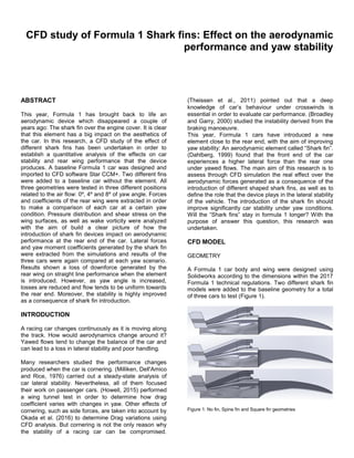
  • 1. CFD study of Formula 1 Shark fins: Effect on the aerodynamic performance and yaw stability ABSTRACT This year, Formula 1 has brought back to life an aerodynamic device which disappeared a couple of years ago: The shark fin over the engine cover. It is clear that this element has a big impact on the aesthetics of the car. In this research, a CFD study of the effect of different shark fins has been undertaken in order to establish a quantitative analysis of the effects on car stability and rear wing performance that the device produces. A baseline Formula 1 car was designed and imported to CFD software Star CCM+. Two different fins were added to a baseline car without the element. All three geometries were tested in three different positions related to the air flow: 0º, 4º and 8º of yaw angle. Forces and coefficients of the rear wing were extracted in order to make a comparison of each car at a certain yaw condition. Pressure distribution and shear stress on the wing surfaces, as well as wake vorticity were analyzed with the aim of build a clear picture of how the introduction of shark fin devices impact on aerodynamic performance at the rear end of the car. Lateral forces and yaw moment coefficients generated by the shark fin were extracted from the simulations and results of the three cars were again compared at each yaw scenario. Results shown a loss of downforce generated by the rear wing on straight line performance when the element is introduced. However, as yaw angle is increased, losses are reduced and flow tends to be uniform towards the rear end. Moreover, the stability is highly improved as a consequence of shark fin introduction. INTRODUCTION A racing car changes continuously as it is moving along the track. How would aerodynamics change around it? Yawed flows tend to change the balance of the car and can lead to a loss in lateral stability and poor handling. Many researchers studied the performance changes produced when the car is cornering. (Milliken, Dell'Amico and Rice, 1976) carried out a steady-state analysis of car lateral stability. Nevertheless, all of them focused their work on passenger cars. (Howell, 2015) performed a wing tunnel test in order to determine how drag coefficient varies with changes in yaw. Other effects of cornering, such as side forces, are taken into account by Okada et al. (2016) to determine Drag variations using CFD analysis. But cornering is not the only reason why the stability of a racing car can be compromised. (Theissen et al., 2011) pointed out that a deep knowledge of car’s behaviour under crosswinds is essential in order to evaluate car performance. (Broadley and Garry, 2000) studied the instability derived from the braking manoeuvre. This year, Formula 1 cars have introduced a new element close to the rear end, with the aim of improving yaw stability: An aerodynamic element called “Shark fin”. (Dahlberg, 1999) found that the front end of the car experiences a higher lateral force than the rear one under yawed flows. The main aim of this research is to assess through CFD simulation the real effect over the aerodynamic forces generated as a consequence of the introduction of different shaped shark fins, as well as to define the role that the device plays in the lateral stability of the vehicle. The introduction of the shark fin should improve significantly car stability under yaw conditions. Will the “Shark fins” stay in formula 1 longer? With the purpose of answer this question, this research was undertaken. CFD MODEL GEOMETRY A Formula 1 car body and wing were designed using Solidworks according to the dimensions within the 2017 Formula 1 technical regulations. Two different shark fin models were added to the baseline geometry for a total of three cars to test (Figure 1). Figure 1: No fin, Spine fin and Square fin geometries
  • 2. CAD models were imported into Star CCM+. All the geometries were combined into different groups according to its relevance in the final results (e.g., Wing was divided into upper and lower surfaces, whereas the body of the car was one single part). MESH VALUES Since the geometry had to be tested in different positions, surface wrapper technique was applied to the model. Another chosen model was Trimmer. The combination of both models was translated into a reduction of computational time spent as expecting regarding results obtained by Pachpund et al. (2012). In terms of mesh size, three different volumes were added to the main geometry with the aim of gently reduce mesh size towards the rear end of the car. Wing and fin mesh sizes were refined since they are goal parts of the research. An example of the refined mesh can be seen in figure 2. Moreover, a contact prevention set was applied to wing planes, in order to avoid the gap to be closed. Figure 2: Example of mesh refined at rear wing BOUNDARY AND PHYSICS CONDITIONS Inlet boundary was given a velocity of 60m/s and outlet was defined as a flow-split boundary type. The flow is considered turbulent. The k-epsilon model was chosen as a turbulence model for all simulations. (Shetty and Patil, 2013) implemented this model in a CFD analysis of the external aerodynamics of a car with positive results. CONVERGENCE Results had been considered as full converged when all residuals were below 1E-03. Results converged after 4000 iterations. RESULTS AND DISCUSSION 0º YAW CASE Forces in the rear wing Forces and force coefficients were extracted from the simulation and can be found in Tables 1 and 2. Results revealed downforce loss of 3.7% in the spine fin case, and about 7.3% whit the use of the Square fin. Furthermore, drag force slightly decreased in both cases. Since downforce reduction is considerable, analysis of the flow was undertaken in order to understand the reason. No fin Spine fin Square fin Yaw CL CD CL CD CL CD 0º 4.610 0.509 4.441 0.471 4.297 0.472 4º 3.675 0.482 3.416 0.465 3.585 0.451 8º 2.736 0.522 2.673 0.482 3.040 0.458 Table 1: Rear wing force coefficients No fin Spine fin Square fin Yaw DF Drag DF Drag DF Drag 0º 1392.2 153.7 1340.7 169.7 1297.3 142.4 4º 1341.3 175.8 1246.4 169.7 1308.2 164.7 8º 1167.1 222.5 1140.2 205.5 1295.6 195.2 Table 2: Rear wing aerodynamic forces (Newtons) Flow structure With the aim of understand the phenomena of force reduction, wake vorticity was measured close to the rear wing. Results can be seen in Figure 3. No fin and Spine fin cases presented similar results, though slightly higher vorticity values can be noticed in the region below the main plane. However, a weak but perceivable vortex structure appeared in the center of the wing, above the flap plane.
  • 3. Figure 3: Vortex structures at the wake for 0º yaw case (No fin, Spine fin, Square fin.) Studying this vortex in depth was observed that is generated in the square fin and continues towards the rear wing. Vortex structure impacts against the main plane, generating the previously mentioned downforce and drag loss. Evolution of this vortex as it moves through the wing can be seen in Figure 4. Figure 4: Vortex evolution through wing main plane Wing pressure distribution Static pressure distribution along the wingspan was extracted from a surrounding area of the leading edge of the main plane (Figure 5) and the flap (Figure 6). Pressure distributions are symmetric as expected. In the main plane, no fin and Spine fin cases show similar distributions except from the two light curves on the upper surface in the Spine fin case. Vortices coming from the fin diverge producing a decrease in pressure, thus decreasing downforce. Nevertheless, those vortices are weak. Figure 5: Static pressure distribution on the main plane The main difference appears in the Square fin case. The vortex created mentioned in the previous sub-section hit the main plane, reducing the pressure in the upper face
  • 4. and increasing it in the lower face. Thus, being the cause of the decrease in downforce found when shark fins were introduced. Figure 6: Static pressure distribution over the flap (0º yaw) Pressure distribution in the flap showed the same results. The fluctuant pressure that appeared on the main plane tips became low pressure zones on the flap as a consequence of vorticity. The inverted peak created by the square fin vortex was also noticed in the upper face of the Shark fin case. 4º YAW CASE Forces in the rear wing All results are shown in Tables 1 and 2. As a result of the yawed flow, a diminution of 3.65% in downforce was noticed with no shark fin in the car compared to the straight line case. Drag force suffered an increase of 14.43%. The introduction of the spine fin did not reported any benefit in terms of drag or downforce at a yaw angle of 4 degrees, showing an important reduction in downforce compared to the car with no fin incorporated drag forces are similar. As expected, the “Square fin” did not show a massive difference over both previous scenarios. However, a lower value of the drag force allows the wing to be more efficient. Flow structure Vorticity in the wake (Figure 7) revealed some of the reasons governing the wing performance. Windward vortices were found to be weaker and leeward ones stronger in all three cases as expected. The structure generated by introducing the spine fin is indicative of the downforce loss in the wing, since vortices are weaker. Introducing the squared fin, vortices tend to be similar to those found in absence of fin and a rise in the central vortex generated by the fin was noted. Figure 7: Wake vorticity for No fin, Spine fin and Square fin. Since this last vortex seemed to be stronger that in the 0º of yaw case, vorticity in the trailing edge location of the shark fin was measured in order to find out its effects over the rear wing. Results in figure 8 show that the structure moved upwards before hitting the rear wing, and as a consequence of that downforce will be higher.
  • 5. Figure 8: Square fin tip vortex Wing pressure distribution The vortex produced by the squared fin has migrated upwards and the inverted peak of the lower main plane surface disappeared. However, small effects of this vortex can still be perceived in the upper surface, with a small pressure decrease towards the center of the wing. Hence, downforce loss between no fin and square fin cases is less. The spine fin case showed a decreased pressure gradient close to the right end plate. That agrees with the weak vortex structured depicted in the previous section, being the reason of performance loss in this case. Peak pressure gradients were displaced right as a consequence of the yawed flow. As expected, the squared fin led the flow slightly straighter towards the rear wing and therefore, the minimum value is closer to the middle plane. In terms of the flap, the flow followed the same pattern showing the decreased pressure gradient in the right zone of the spine fin case. In the windward side of the square fin case a bigger pressure gradient was noticed, due to better flow alignment. Figure 9: Pressure distributions in the rear wing at 4º of yaw 8 DEGREES OF YAW Forces in the rear wing As expected, the biggest difference was seen with a yaw angle of 8 degrees. In the car with no fin the flow detaches from the lower surface of the main plane, causing a notable loss of downforce. Since the “Spine fin” is not long enough to drive the flow straight towards the rear wing, flow detachment was seen, although the drag force is reduced in 7.6%. The “Square fin” had the biggest impact over wing performance. A more symmetric pressure distribution is translated into a less flow detachment over the wing. Hence a substantial increase in downforce and a slightly lower drag force generated enhances the efficiency of the wing. Flow structure Windward tip vortices were stronger than the other 2 cases. At high yaw conditions, the fin aligns the flow with the rear wing and generates more suction, enhancing downforce.
  • 6. Figure 10: Wake vorticity for No fin, Spine fin and Square fin at 8º yaw In this case, wall shear stress (Figure 11) helped to understand the effect of the fin. The flow in the lower surface of the windward side detached and generated a vortex close to the endplate. The effect disappeared with the introduction of the spine fin and square fin increased the stress on that zone, revealing that flow alignment is better. Separation and downforce loss in the no fin case was expected regarding the results obtained in (Gogel and Sakurai, 2006). Figure 11: Wall shear stress. Left to right: No fin, Spine fin and Square fin This separation and downforce loss in the no fin case was expected regarding the results obtained in ( Wing pressure distribution Figure 12 shows static pressure in the wing. In the main plane a decrease in pressure in the square fin case was perceived. That leads to an increment in rear downforce. The minimum pressure peak was also displaced to the center of the main plane, since flow hit the rear wing straighter. Figure 12: Wing pressure distribution at 8º yaw In terms of the flap, the windward side showed higher pressure in the no fin case as a consequence of the flow separation produced. Improvements can be seen with the introduction of the fins, being the square fin case the most favorable. EFFECT ON PERFORMANCE AND STABILITY From a cornering point of view, the introduction of a massive plate at the rear end of the car would surely produce an important handling change. With the purpose of measure the impact of the shark fin, yaw moment coefficients were extracted from the model.
  • 7. Figure 13: Yaw moment coefficient variation Figure 13 displays the yaw moment coefficient for each car at the different tested yaw angles. As can be perceived straightforward, both square and spine fins increase the yaw moment in the opposite direction of the steering angle. However, curves corresponding to the no fin and spine fin cases followed a similar tendency when yaw angle becomes more extreme, whereas the shark fin still increases until a value of -0.7076, which almost doubles the value found in the no fin case. Static pressure distribution over both sides of the shark fin showed a notable differential pressure between left and right surfaces producing a net side force. This lateral force improves the stability of the car in potential oversteering situations. Lateral forces generated also allow the car to drive faster through corners. In addition to these effects, downforce increase helps making the car stable. (Howell and Le Good, 1999) stated the effect of lift in yaw stability. CONCLUSION A CFD analysis of how the introduction of shark fins affects the performance and stability of a F1 car has been carried out. In terms of performance, downforce loss is experienced in straight line with the presence of the square shark fin. The longer the element, the greater the decrease in downforce experienced. However, the curve of performance loss is less pronounced when yaw angle is increased. Regarding stability, results confirm that for big side areas in the rear, stability is largely improved. The square fin improves stability in cornering and crosswind conditions. Results show that the benefits obtained in yawed conditions using the square fin are larger than the loss of wing performance experienced in straight line. It is also clear as well that the spine fin does not report the benefits of the square fin at yaw, stating that intermediate solutions are not convenient. REFERENCES 1. Milliken, W., Dell'Amico, F. and Rice, R. (1976). The Static Directional Stability and Control of the Automobile. SAE Technical Paper Series. 2. Howell, J. (2015). Aerodynamic Drag of Passenger Cars at Yaw. SAE International Journal of Passenger Cars - Mechanical Systems, 8(1).. 3. Okada, Y., Nakashima, T., Tsubokura, M., Morikawa, Y., Kouno, R., Okamoto, S., Matsuhiro, T. and Nouzawa, T. (2016). Aerodynamics Evaluation of Road Vehicles in Dynamic Maneuvering. SAE Technical Paper Series. 4. Theissen, P., Wojciak, J., Heuler, K., Demuth, R., Indinger, T. and Adams, N. (2011). Experimental Investigation of Unsteady Vehicle Aerodynamics under Time-Dependent Flow Conditions - Part 1. SAE Technical Paper Series. 5. Dahlberg, E. (1999). Yaw Instability Due to Longitudinal Load Transfer During Braking in a Curve. SAE Technical Paper Series. 6. Broadley, I. and Garry, K. (2000). Improving the Aerodynamic Stability of a Practical, Low Drag, Aero-Stable Vehicle. SAE Technical Paper Series. 7. Shetty, S. and patil, V. (2013). Recent Advances in External Aerodynamics Simulation of a Hatchback Production Car. SAE Technical Paper Series. 8. Pachpund, S., Madhavan, J., Pandit, G. and Chimner, T. (2012). Development of CFD Methodology for Drag Force Prediction on Passenger Car with Rear Mounted Spoiler. SAE Technical Paper Series. 9. Gogel, D. and Sakurai, H. (2006). The Effects of End Plates on Downforce in Yaw. SAE Technical Paper Series. 10. Howell, J. and Le Good, G. (1999). The Influence of Aerodynamic Lift on High Speed Stability. SAE Technical Paper Series.