Download to read offline
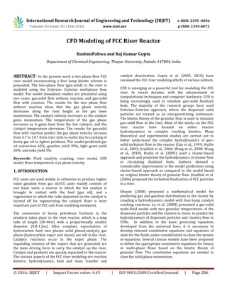
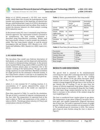
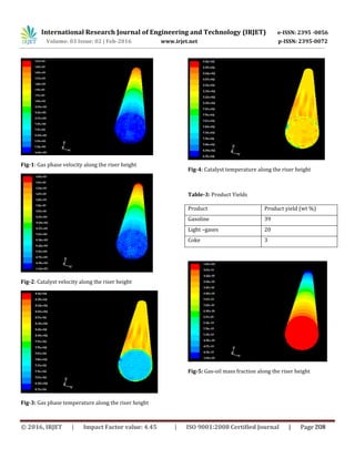
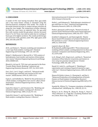

1) The document presents a CFD model of a fluid catalytic cracking (FCC) riser reactor using an Eulerian-Eulerian multiphase approach to model the gas-solid flow. 2) A four-lump kinetic scheme is used to model the catalytic cracking reactions, and heat transfer between the gas and catalyst phases is modeled using the Ranz-Marshall correlation. 3) The model predicts an increase in gas velocity and a decrease in catalyst temperature along the riser height due to catalytic cracking reactions converting the heavy gas oil feed into lighter products. Product yields of gasoline, light gases, and coke are estimated.


![[Transport]modeling of oil product and gas pipeline transportation](https://cdn.slidesharecdn.com/ss_thumbnails/transportmodelingofoilproductandgaspipelinetransportation-150701063047-lva1-app6892-thumbnail.jpg?width=640&height=640&fit=bounds)


