The document provides instructions for completing a practice skills exam on CCNA topics including IPv4 and IPv6 addressing, router and switch configuration, and device security. It includes requirements for configuring a town hall router, administration switch, and various hosts. The summary is:
1) Configure IPv4 and IPv6 addressing for routers, switches and hosts.
2) Hardened the town hall router's security and configured interfaces.
3) Enabled management on the administration switch.
4) Addressed and configured hosts with IPv4 and IPv6.
5) Backed up the town hall router configuration to a TFTP server.
Cisco CCNA Training/Exam Tips that are helpful for your Certification Exam!
To be Cisco Certified please Check out:
http://asmed.com/information-technology-it/
Cisco CCNA Training/Exam Tips that are helpful for your Certification Exam!
To be Cisco Certified please Check out:
http://asmed.com/information-technology-it/
Cisco CCNA Training/Exam Tips that are helpful for your Certification Exam!
To be Cisco Certified please Check out:
http://asmed.com/information-technology-it/
Cisco CCNA Training/Exam Tips that are helpful for your Certification Exam!
To be Cisco Certified please Check out:
http://asmed.com/information-technology-it/
Cisco CCNA Training/Exam Tips that are helpful for your Certification Exam!
To be Cisco Certified please Check out:
http://asmed.com/information-technology-it/
Cisco CCNA Training/Exam Tips that are helpful for your Certification Exam!
To be Cisco Certified please Check out:
http://asmed.com/information-technology-it/
CCNA: Connecting Networks SA Exam
Lab 13 CCNA: Connecting Networks
CSIS 430 – Weeks 1 - 4
Hands-On Skills Assessment
Topology
Complete the assessment in Packet Tracer and document and fill in the blanks. Submit this file and the pka file in Week 8 Lab 13, Points will not be given for incomplete Steps.
Assessment Objectives
Part 1: Initialize Devices (2 points, 5 minutes)
Part 2: Configure Device Basic Settings (8 points, 20 minutes)
Part 3: Configure PPP Connections (7 points, 20 minutes)
Part 4: Configure NAT (4 points, 15 minutes)
Part 5: Monitor the Network (6 points, 15 minutes)
Part 6: Configure Frame Relay (7 points, 20 minutes)
Part 7: Configure a GRE VPN Tunnel (6 points, 20 minutes)
Scenario
In this Skills Assessment (SA) you will create a small network. You must connect the network devices and configure those devices to support various WAN protocols. This will require that you reload the routers before starting your configuration of the next WAN protocol. The assessment has you save your basic device configurations to flash prior to implementing a WAN protocol to allow you to restore these basic configurations after each reload.
The first WAN protocol you will configure is Point-to-Point Protocol (PPP) with CHAP authentication. You will also configure Network Address Translation (NAT), and network monitoring protocols during this phase of the assessment. After your instructor has signed off on this phase, you will reload the routers and configure Frame Relay. After the Frame Relay part is complete, and has been signed off by your instructor, you will reload the routers and configure a GRE VPN tunnel. Network configurations and connectivity will be verified throughout the assessment by using common CLI commands.
Required Resources
3 Routers (Cisco 1941 with Cisco IOS Release 15.2(4)M3 universal image or comparable)
3 PCs (Windows 7, Vista, or XP with terminal emulation program, such as Tera Term.
Console cable to configure the Cisco IOS devices via the console ports
Ethernet and Serial cables as shown in the topology
Initialize Devices
Total points: 2
Time: 5 minutes
Initialize and reload routers.
Erase the startup configurations and reload the devices.
Task
IOS Command
Points
Erase the startup-config file on all routers.
erase startup-config
(1 point)
Reload all routers.
reload
(1 point)
Points: __________ of 2
Configure Device Basic Settings
Total points: 8
Time: 20 minutes
Configure PCs.
Assign static IPv4 address information (IP address, subnet mask, default gateway) to the three PCs in the topology. Refer to the Topology diagram to obtain the IP address information.
Configuration Item or Task
Specification
Points
Configure static IPv4 address information on PC-A.
IP Address: 192.168.11.3
Subnet Mask: 255.255.255.0
Default Gateway: 192.168.11.1
1
Configure static IPv4 address information on PC-B.
IP Address: 192.168.22.3
Subnet Mask: 255.255.255.0
Default Gateway: 192.168.22.1
Configure static IPv4 address information on PC ...
Konfigurasi Server Gateway dengan fitur PROXY, WEBSERVER dan DHCPWalid Umar
Panduan diatas dikhusukan untuk siswa dan guru TKJ yang hendak mempraktekkan tentang panduan untuk membangun sebuah server gateway dengan fitur proxy, webserver dan dhcp
ACME Corp. 205.1.100.14/302001:DB8:CAFE:1:.15/64 205.1.100.13/302001:DB8:CAFE:1:1/64
Corporate LAN ISP - Management VLAN 100: 172.16.100.0/24 - RnD VLAN 10: 10.10.0.0/16 -
Finance VLAN 20: 10.20.0.0/16 - Staff VLAN 30: 10.30.0.0/16 RnD's Experimental PVv Network:
2001:DB8:ACAD:1::64 On the Corporate LAN - VLAN 900 has been assigned the Native VLAN
and is not routable.Addressing Table To assist with connectivity te:SW-1 and SW-2 VLAN
Assignment Table EtherChannel Port Assignment Table The IEEE 802. 3ad open standard, Link
Aggregation Control Protocol (LACP) will be used for the EtherChannel between SW-1 and SW-
2.Router Pre-configurations The following pre-configurations have been applied to the Core router
- Hostname: Core - The router is protected from unauthorized access using a privileged exec
password of cisco - The assigned console password is class. - The VTY lines of the router have
been configured to only accept $SH type connections. - The SSH service has been configured to
use acme.com as the IP domain name and 1024 is the selected Modulus bit value. - For
authenticating SSH connections, locally configured credentials with the highest administrative
privileges available, have been set. Username: netadmin Secret Password: cisco - All service
passwords have been encrypted. - The banner MOTD message has been configured. - Interface
GO/O/1, has already been configured and enabled for IPv4 and IPv6 communication with the ISP
router. Instructions Part 1: On the Core router, complete the following configurations Step 1: On
interface Govov of the Core router, complete the remaining interface and sub-interface
configuration to support inter-VLAN routing. a. Using the Address information provided in the
Addressing Table configure and enable, on the Core router, interface Gorovo and all of its
corresponding subinterlaces. b. The sub-interface on GONar that corresponds with VLAN 900
should be configured as native, but it should NOT be routable. Step 2: Enable IPv6 Stateless
Address Autoconfiguration (SLAAC) for the RnD Experimental Network on the Core router. Step 3:
Configure DHCP pools for both the Finance and the Staff VLANs. a. Configure separate DHCP
pools for the Finance and Staff VLANs: 1) DHCP pool names: Finance and Staff 2) Using the
network address information identified in the VLAN Assignment Table configure both DHCP pools.
3) Exclude from the DHCP pool the router interface address for each corresponding VLAN. 3)
Setup each pool to also provide hosts with their corresponding default gateway address.Note: To
expedite successful completion of the Skills Assessment, all necessary configuration tasks have
already been applied on SW-2. Thus, the following onfiguration tasks need only to be completed
on SW-1. Step 1: Configure VLANs on SW-1 Using the information provided in the SW-1 and SW-
2 VLAN Assignment Table, create and name the identified VLANs on SW-1. Step 2: Assign
Access Ports to VLANs. For each host on SW-1, assign the connect.
ITNE2003 - AssignmentLearning ObjectivesUpon completion of this.docxsleeperfindley
ITNE2003 - Assignment
Learning Objectives
Upon completion of this assignment, you will be able to:
Subnet an address space given requirements.
Assign appropriate addresses to interfaces and document them in the Addressing Table.
Cable a network according to the Topology Diagram.
Erase the startup configuration and reload a router to the default state.
Configure RIPv2 routing on all routers.
Configure and propagate a static default route.
Verify RIPv2 operation.
Test and verify full connectivity.
Reflect upon and document the network implementation.
Scenario
In this lab activity, you will be given a network diagram that must be implemented in packet tracer. A combination of RIPv2 and static routing will be required so that hosts on networks that are not directly connected will be able to communicate with each other.
Topology Diagram
Task 1: Fill Addressing Table:
Step 1: Examine the network requirements.
The addressing for the network has the following requirements:
The ISP LAN will use the 203.162.108.0/24 network.
The link between the ISP router and the HQ router will use the 172.16.10.0/30 network.
The link between the BRANCH router and the HQ router will use the 172.16.10.4/30 network.
The HQ LAN will use the 192.168.1.128/25 network
The BRANCH LAN will use the 10.10.2.0/23 network.
(
Note:
Remember that the interfaces of network devices are also host IP addresses and are included in the above addressing requirements.)
Step 2: Fill the address table with appropriate IP addresses and subnet masks:
Device
Interface
IP Address
Subnet Mask
Default Gateway
BRANCH
Fa0/0
N/A
S0/0/0
N/A
HQ
Fa0/0
N/A
S0/0/0
N/A
S0/0/1
N/A
ISP
Fa0/0
N/A
S0/0/1
N/A
PC1
NIC
PC2
NIC
PC3
NIC
Task 2: Implement the Network.
Step 1: Cable a network that is similar to the one in the Topology Diagram in Packet Tracer.
You can use any current router in your lab as long as it has the required interfaces shown in the topology.
Note:
If you use 1700, 2500, or 2600 routers, the router outputs and interface descriptions will appear different.
Step 2: Perform basic administrative configuration in the BRANCH, HQ, and ISP routers
Configure the router hostname as the minimum
Task 3: Configure and Activate Serial and Ethernet Addresses.
Step 1: Configure the BRANCH, HQ, and ISP routers.
Configure the interfaces on the BRANCH, HQ, and ISP routers with the IP addresses from the Addressing Table provided under the Topology Diagram.
When you have finished, be sure to save the running configuration to the NVRAM of the router.
Step 2: Configure the Ethernet interfaces of PC1, PC2, and PC3.
Configure the Ethernet interfaces of PC1, PC2, and PC3 with the IP addresses from the Addressing Table provided under the Topology Diagram.
Task 4: Verify Connectivity to Next-Hop Device.
You should
not
have connectivity between end devices yet. However, you can test connectivity between two routers and between an end device and its default gateway.
Step 1: Verify BR.
CCIE Collaboration Bootcamp is designed to be a challenging five-day course for CCIE Collaboration candidates ready for CCIE Collaboration Lab Exam. This Bootcamp is designed for CCIE Collaboration candidates in the last months or weeks before their CCIE Collaboration Lab Exam. During the week students will tackle challenging full-day mock labs Monday through Thursday. Candidate will practice strategy, time management, learn test taking strategies and expose any weaknesses in order to resolve them before the lab exam. On the final day of the course
A Strategic Approach: GenAI in EducationPeter Windle
Artificial Intelligence (AI) technologies such as Generative AI, Image Generators and Large Language Models have had a dramatic impact on teaching, learning and assessment over the past 18 months. The most immediate threat AI posed was to Academic Integrity with Higher Education Institutes (HEIs) focusing their efforts on combating the use of GenAI in assessment. Guidelines were developed for staff and students, policies put in place too. Innovative educators have forged paths in the use of Generative AI for teaching, learning and assessments leading to pockets of transformation springing up across HEIs, often with little or no top-down guidance, support or direction.
This Gasta posits a strategic approach to integrating AI into HEIs to prepare staff, students and the curriculum for an evolving world and workplace. We will highlight the advantages of working with these technologies beyond the realm of teaching, learning and assessment by considering prompt engineering skills, industry impact, curriculum changes, and the need for staff upskilling. In contrast, not engaging strategically with Generative AI poses risks, including falling behind peers, missed opportunities and failing to ensure our graduates remain employable. The rapid evolution of AI technologies necessitates a proactive and strategic approach if we are to remain relevant.
Synthetic Fiber Construction in lab .pptxPavel ( NSTU)
Synthetic fiber production is a fascinating and complex field that blends chemistry, engineering, and environmental science. By understanding these aspects, students can gain a comprehensive view of synthetic fiber production, its impact on society and the environment, and the potential for future innovations. Synthetic fibers play a crucial role in modern society, impacting various aspects of daily life, industry, and the environment. ynthetic fibers are integral to modern life, offering a range of benefits from cost-effectiveness and versatility to innovative applications and performance characteristics. While they pose environmental challenges, ongoing research and development aim to create more sustainable and eco-friendly alternatives. Understanding the importance of synthetic fibers helps in appreciating their role in the economy, industry, and daily life, while also emphasizing the need for sustainable practices and innovation.
Operation “Blue Star” is the only event in the history of Independent India where the state went into war with its own people. Even after about 40 years it is not clear if it was culmination of states anger over people of the region, a political game of power or start of dictatorial chapter in the democratic setup.
The people of Punjab felt alienated from main stream due to denial of their just demands during a long democratic struggle since independence. As it happen all over the word, it led to militant struggle with great loss of lives of military, police and civilian personnel. Killing of Indira Gandhi and massacre of innocent Sikhs in Delhi and other India cities was also associated with this movement.
Introduction to AI for Nonprofits with Tapp NetworkTechSoup
Dive into the world of AI! Experts Jon Hill and Tareq Monaur will guide you through AI's role in enhancing nonprofit websites and basic marketing strategies, making it easy to understand and apply.
Read| The latest issue of The Challenger is here! We are thrilled to announce that our school paper has qualified for the NATIONAL SCHOOLS PRESS CONFERENCE (NSPC) 2024. Thank you for your unwavering support and trust. Dive into the stories that made us stand out!
Biological screening of herbal drugs: Introduction and Need for
Phyto-Pharmacological Screening, New Strategies for evaluating
Natural Products, In vitro evaluation techniques for Antioxidants, Antimicrobial and Anticancer drugs. In vivo evaluation techniques
for Anti-inflammatory, Antiulcer, Anticancer, Wound healing, Antidiabetic, Hepatoprotective, Cardio protective, Diuretics and
Antifertility, Toxicity studies as per OECD guidelines
Francesca Gottschalk - How can education support child empowerment.pptxEduSkills OECD
Francesca Gottschalk from the OECD’s Centre for Educational Research and Innovation presents at the Ask an Expert Webinar: How can education support child empowerment?
Acetabularia Information For Class 9 .docxvaibhavrinwa19
Acetabularia acetabulum is a single-celled green alga that in its vegetative state is morphologically differentiated into a basal rhizoid and an axially elongated stalk, which bears whorls of branching hairs. The single diploid nucleus resides in the rhizoid.
The French Revolution, which began in 1789, was a period of radical social and political upheaval in France. It marked the decline of absolute monarchies, the rise of secular and democratic republics, and the eventual rise of Napoleon Bonaparte. This revolutionary period is crucial in understanding the transition from feudalism to modernity in Europe.
For more information, visit-www.vavaclasses.com
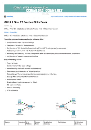
1. ccnav5.org http://ccnav5.org/ccna-1-final-pt-practice-skills-exam/?pfstyle=wp
CCNAV5.Org
CCNAv5.Org
CCNA 1 Final PT Practice Skills Exam
CCNA 1 Final v5.0 Introduction to Networks Practice Final – CLI command answers
CCNA 1 Exam 2014
CCNA1 v5.0 Introduction to Networks Final – CLI command answers
You will practice and be assessed on the following skills:
Configuration of initial IOS device settings
Design and calculation of IPv4 addressing
Configuration of IOS device interfaces including IPv4 and IPv6 addressing when appropriate
Addressing of network hosts with IPv4 and IPv6 addresses
Enhancing device security, including configuration of the secure transport protocol for remote device configuration
Configuration of a switch management interface
Requirements by device:
Town Hall router:
Configuration of initial router settings
Interface configuration and IPv4 and IPv6 addressing
Device security enhancement or “device hardening”
Secure transport for remote configuration connections as covered in the labs.
Backup of the configuration file to a TFTP server
Administration Switch:
Enabling basic remote management by Telnet
PC and Server hosts:
IPv4 full addressing
IPv6 addressing
Device Interface IPv4
Address
Subnet
Mask
IPv4 Default
Gateway
IPv6 Address IPv6 Default
Gateway
2. Town Hall G0/0 N/A 2001:DB8:ACAD:A::1/64 N/A
G0/1 N/A 2001:DB8:ACAD:B::1/64 N/A
Administration
Switch
Vlan 1 N/A N/A
Reception Host NIC 2001:DB8:ACAD:A::FF
Operator Host NIC 2001:DB8:ACAD:A::15
IT Host NIC 2001:DB8:ACAD:B::FF
TFTP Server NIC 2001:DB8:ACAD:B::15
Step 1:
Design an IPv4 addressing scheme and complete the Addressing Table based on the following requirements. Use the table
above to help you organize your work.
a. Subnet the 192.168.1.0/24 network to provide 30 host addresses per subnet while wasting the fewest addresses.
b. Assign the fourth subnet to the IT Department LAN.
c. Assign the last network host address (the highest) in this subnet to the G0/0 interface on Town Hall.
d. Starting with the fifth subnet, subnet the network again so that the new subnets will provide 14 host addresses per subnet
while wasting the fewest addresses.
e. Assign the second of these new 14-host subnets to the Administration LAN.
f. Assign the last network host address (the highest) in the Administration LAN subnet to the G0/1 interface of the Town Hall
router.
g. Assign the second to the last address (the second highest) in this subnet to the VLAN 1 interface of the Administration Switch.
h. Configure addresses on the hosts using any of the remaining addresses in their respective subnets.
Step 2: Configure the Town Hall Router.
a. Configure the Town Hall router with all initial configurations that you have learned in the course so far:
· Configure the router hostname: Middle
· Protect device configurations from unauthorized access with the encrypted password.
· Secure all of the ways to access the router using methods covered in the course and labs.
· Newly-entered passwords must have a minimum length of 10 characters.
· Prevent all passwords from being viewed in clear text in device configuration files.
· Configure the router to only accept in-band management connections over the protocol that is more secure than Telnet, as was
done in the labs. Use the value 1024 for encryption key strength.
· Configure user authentication for in-band management connections.
b. Configure the two Gigabit Ethernet interfaces using the IPv4 addressing values you calculated and the IPv6 values provided in
the addressing table.
· Reconfigure the link local addresses as was practiced in the labs. The IPv6 link-local Interface ID should match the IPv6
unicast Interface ID as is practiced in the labs.
· Document the interfaces in the configuration file.
Step 3: Configure the Administration Switch.
3. Configure Administration Switch for remote management.
Step 4: Configure and Verify Host Addressing.
a. Use the IPv4 addressing from Step 1 and the IPv6 addressing values provided in the addressing table to configure all host
PCs with the correct addressing.
b. Use the router interface link-local addresses as the IPv6 default gateways on the hosts.
c. All hosts should be able to ping each other over IPv4.
Step 5: Backup the Configuration of the Town Hall Router to TFTP.
a. Complete the configuration of the TFTP server using the IPv4 addressing values from Step 1 and the values in the addressing
table.
b. Backup the running configuration of Town Hall to the TFTP Server. Use the default file name.
Answer
Router>
Router>enable
Router#configure terminal
Router(config)#interface g0/0
Router(config-if)#ip address 192.168.1.126 255.255.255.224
Router(config-if)#description IT Department LAN
Router(config-if)#no shutdown
Router(config-if)#exit
Router(config)#interface g0/1
Router(config-if)#ip address 192.168.1.158 255.255.255.240
Router(config-if)#description Administration LAN
Router(config-if)#no shutdown
Router(config-if)#exit
Router(config)#ipv6 unicast-routing
Router(config)#interface g0/0
Router(config-if)#ipv6 address 2001:db8:acad:A::1/64
Router(config-if)#ipv6 address FE80::1 link-local
Router(config-if)#no shutdown
Router(config-if)#exit
Router(config)#interface g0/1
Router(config-if)#ipv6 address 2001:db8:acad:B::1/64
Router(config-if)#ipv6 address FE80::1 link-local
Router(config-if)#no shutdown
Router(config-if)#exit
Router(config)#
Router(config)#hostname Middle
Middle(config)#Enable secret class12345
Middle(config)#line console 0
Middle(config-line)#password cisconet2014
Middle(config-line)#login
Middle(config-line)#exit
Middle(config)#line vty 0 15
Middle(config-line)#password cisconet2014
Middle(config-line)#login
Middle(config-line)#exit
Middle(config)#line aux 0
Middle(config-line)#password cisconet2014
Middle(config-line)#login
Middle(config-line)#exit
Middle(config)#
Middle(config)#Banner motd “Authorized Access Only”
4. Middle(config)#security password min-length 10
Middle(config)#service password-encryption
Middle(config)#ip domain-name ccna5.net
Middle(config)#username cisco secret cisconet2014
Middle(config)#crypto key generate rsa
The name for the keys will be: Middle.cisco.local
Choose the size of the key modulus in the range of 360 to 2048 for your
General Purpose Keys. Choosing a key modulus greater than 512 may take
a few minutes.
How many bits in the modulus [512]: 1024
% Generating 1024 bit RSA keys, keys will be non-exportable…[OK]
Middle(config)#line vty 0 15
Middle(config-line)#login local
Middle(config-line)#transport input ssh
Middle(config-line)#exit
Middle(config)#
—————————————–
Switch1 ip default gateway 192.168.1.158
—————————————–
Reception Host
default gateway FE80::1
default gateway 192.168.1.126
IP address 192.168.1.97/27
IPv6 address 2001:DB8:ACAD:A::FF/64
—————————————–
Operator Host
default gateway FE80::1
default gateway 192.168.1.126
IP address 192.168.1.98/27
IPv6 address 2001:DB8:ACAD:A::15/64
—————————————–
IT Host
default gateway FE80::1
default gateway 192.168.1.158
IP address 192.168.1.145/28
IPv6 address 2001:DB8:ACAD:B::FF/64
—————————————–
SERVER TFTP
default gateway FE80::1
default gateway 192.168.1.158
IP address 192.168.1.146/28
IPv6 address 2001:DB8:ACAD:B::15/64
—————————————–
Backup the Configuration of the Town Hall Router to TFTP.
Middle#copy running-config tftp
5. Address or name of remote host []? 192.168.1.146
Destination filename [Router-confg]? [Press Enter]
—————————————–