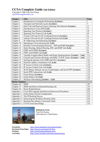
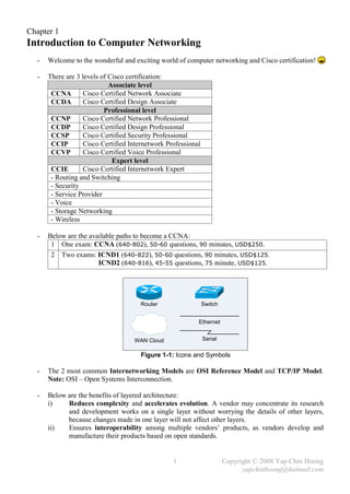
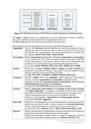
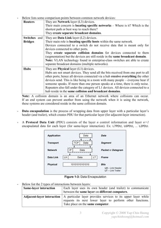
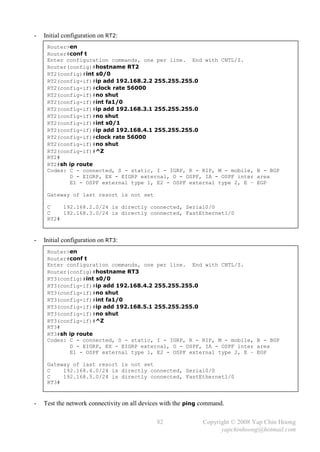
The document summarizes a CCNA Complete Guide 2nd Edition book that covers the CCNA 640-802 exam syllabus. It contains theory and practical knowledge needed to pass the CCNA exam and work as a network engineer. The book includes lab setups and outputs to verify concepts. Obtaining this guide is described as the best investment for becoming an accomplished network engineer.

![- The following section discusses several TCP/IP network layer utility protocols.
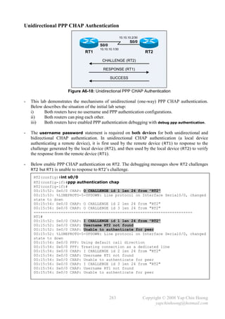
- Address Resolution Protocol (ARP) When IP (L3) has a packet to send, it must supply the
destination host’s hardware address to a network access protocol, eg: Ethernet or Token Ring.
IP will first try to find the information from the ARP cache. If IP is unable to find it from the
ARP cache, it uses ARP to dynamically discover or learn the MAC address for a particular IP
network layer address. A sender must know the physical or MAC address of the destination host
before sending out the data. Basically ARP resolves an IP address (software logical address)
to a MAC address (hardware physical address).
- ARP Requests are L2 broadcasts. Since Ethernet is a broadcast media, hence all devices on a
segment will receive an ARP Request. However, only the device with the requested L3 address
will answer the ARP Request by sending a unicast ARP Reply back to the device that sent the
ARP Request. The sender will then have the IP and MAC addresses for data transmission.
Note: The sender might need to send out DNS request to resolve the hostname of the destination
host into IP address prior to the ARP Request-Reply process.
- Hubs and repeaters are typically signal amplifiers, while switches do forward broadcasts out all
ports except the incoming port. In fact they have no impact on ARP traffic.
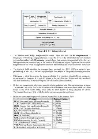
- The show arp EXEC command displays the entries in the ARP cache.
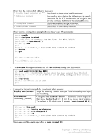
- Proxy ARP happens when a network device replies to an ARP Request on behave of another
device with the MAC address of the interface that received the ARP Request. The ARP caches of
end systems might need to be flushed (with the arp –d command) whenever a Proxy ARP
device is being introduced into a network.
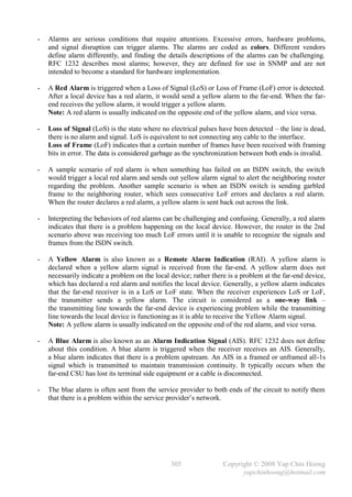
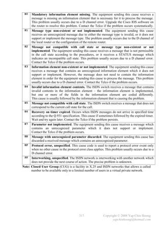
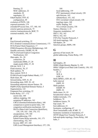
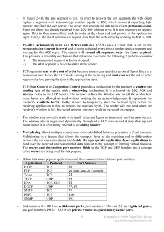
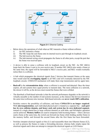
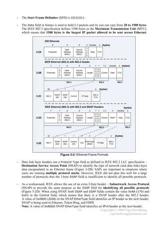
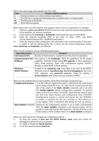
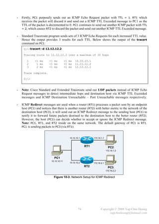
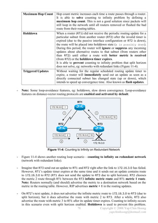
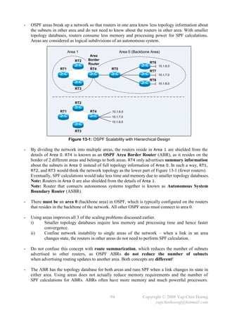
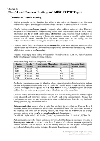
E0 E1
RT1
PC1 E0 IP: 10.1.1.1 / 24 PC2
IP: 10.1.1.2 / 16 E0 MAC: BB-BB-BB-BB-BB-BB IP: 10.1.2.2 / 16
MAC: AA-AA-AA-AA-AA-AA E1 IP: 10.1.2.1 / 24 MAC: DD-DD-DD-DD-DD-DD
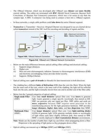
E1 MAC: CC-CC-CC-CC-CC-CC
Figure 2-9: Network Setup for Proxy ARP
- Routers do not forward L2 and L3 broadcasts. Figure 2-9 shows a typical Proxy ARP scenario.
Since PC1 and PC2 IP addresses are reside in the same subnet (10.1.0.0/16), PC1 will assume it
is in the same segment with PC2. Problems arise as there is a router separates the 2 devices into
different broadcast domains, which the ARP broadcast traffic will not be forwarded.
- RT1, the Cisco router will answer the ARP Request sent by PC1 on behave of PC2 with the MAC
address of the interface that received the ARP Request – BB-BB-BB-BB-BB-BB. When PC1
receives the ARP Reply from RT1, it assumes the MAC address of PC2 is BB-BB-BB-BB-BB-BB.
Finally, further traffic destined to PC2 will have 10.1.2.2 as the destination IP address and
encapsulated with the MAC address BB-BB-BB-BB-BB-BB instead of DD-DD-DD-DD-DD-DD.
- Proxy ARP is enabled by default on Cisco routers. It can be enabled or disabled with the
[no] ip proxy-arp interface subcommand respectively. Proxy ARP is not really a protocol;
it is a service offered by routers.
14 Copyright © 2008 Yap Chin Hoong
yapchinhoong@hotmail.com](https://image.slidesharecdn.com/ccna2ndedition-12877133651663-phpapp02/85/Ccna-2nd-Edition-17-320.jpg)

![Chapter 4
Introduction to Cisco IOS
- Almost all current Cisco routers and switches run Cisco IOS (Internetwork Operating System),
the routing and switching software in Cisco devices.
- Cisco IOS command-line interface (CLI) is the text-based user interface to a Cisco device for
configuring, administering, and managing the Cisco device.
- CLI can be accessed through:
i) Console with a rollover cable and terminal emulator application. [line console 0]
ii) AUX through a dialup device such as modem for out-of-band management. The modem
is connected with a straight-through cable to the auxiliary port. [line aux 0]
iii) In-band management through the network via Telnet or SSH. [line vty 0 4]
- Below lists the main Cisco IOS modes:
User EXEC mode Least privileges and limited access. Only provides a set of non-
destructive show commands that allow examination of configuration.
Privileged mode More show commands, and limited configuration commands.
Configuration mode Configuration commands are being entered in this mode. Unable to
check status with the series of show commands. Sub-divided into
some child modes, eg: interface configuration mode, line configuration
mode, router configuration mode, etc.
Commands entered in this mode update the active or running
configuration immediately after the Enter button is pressed.
Configuration commands can be divided into global configuration
commands and subcommands, eg: interface subcommand,
subinterface subcommand, controller subcommand, line subcommand,
router subcommand, etc.
- Below describes some basic Cisco IOS commands:
enable Switches from EXEC mode to privileged mode.
disable Switches from privileged mode back to EXEC mode.
show version Views the basic configuration of the system hardware, software
version, the name and source of the system boot image, etc.
configure terminal Switches from privileged mode to global configuration mode.
hostname Changes the hostname of a Cisco device.
^Z / end / exit Exits from the global configuration mode back to privileged mode.
exit / quit Exits from the EXEC mode.
- Some special IOS CLI features are Context-Sensitive Help with [?] and Auto-Completion
with [TAB] can be used to display or auto-complete the available commands or parameters.
- The context-sensitive help is divided into word help and command syntax help.
word help Ex: cl? – Displays any command or syntax that starts with cl.
command syntax help Ex: clock ? – Displays the available parameters after the clock
command.
Note: The escape sequence for entering the ? character is Ctrl+V.
31 Copyright © 2008 Yap Chin Hoong
yapchinhoong@hotmail.com](https://image.slidesharecdn.com/ccna2ndedition-12877133651663-phpapp02/85/Ccna-2nd-Edition-34-320.jpg)
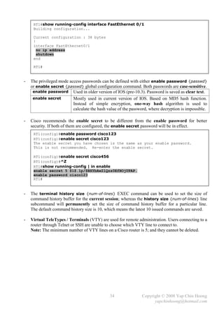
![- Cisco IOS treats a mistyped command as a hostname and will try to resolve it using DNS.
DNS resolution is a time consuming process and is enabled by default, but DNS server is rarely
deployed in lab environments. The no ip domain-lookup global configuration command
disables this default feature.
- The erase startup-config and erase nvram: privileged commands can be used to erase the
startup-config in the NVRAM, which cause a Cisco router or switch to perform factory reset and
enter into the initial configuration dialog upon next reboot.
- The reload [at hh:mm day month | in reload-delay] [reason] privileged command warm
boot a Cisco device. The reload cancel privileged command cancels a scheduled reboot.
- Below lists the types of memory that can be found in Cisco devices:
RAM Used as working storage for packet buffers, ARP cache, routing tables, etc.
The running-config is being stored here.
ROM Normally stores a limited-function bootable IOS image – bootstrap code,
which is not intended for normal operation and is loaded after the POST to
locate and load the full IOS image or ROMmon (the bootstrap code itself)
by examining the configuration register.
Flash memory Either an Intel EEPROM or a PCMCIA card. It is an erasable, rewriteable
and permanent storage. It stores fully functional IOS images and is the
default location where a device obtains its IOS at boot time. It can be used to
store any other files as well (some routers can store configuration files here).
The show flash: privileged command can be used to view the contents of
the Flash memory.
NVRAM Nonvolatile RAM that stores the startup-config.
EEPROM – Electronically Erasable Programmable Read-Only Memory.
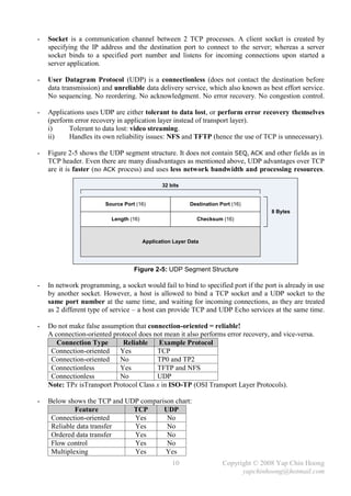
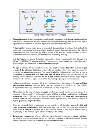
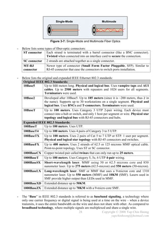
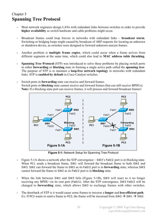
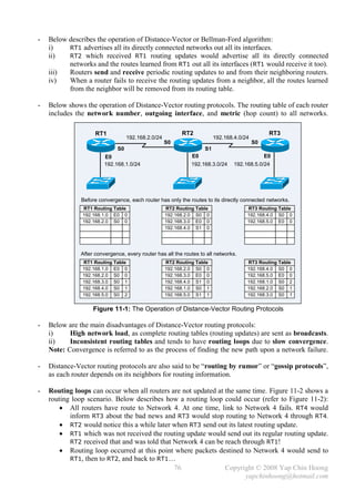
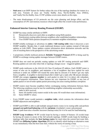
- The copy {source-file} {destination-file} privileged command is used to copy files.
It is mainly used to duplicate configuration files as well as backup and upgrade of IOS images.
copy running-config startup-config copy startup-config tftp
RAM NVRAM TFTP
copy startup-config running-config copy tftp startup-config
(merge)
copy running-config tftp
copy tftp running-config (merge)
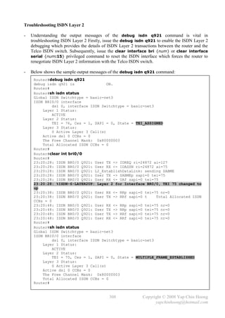
Figure 4-1: The IOS Copy Operations
- During the IOS upgrade process, the device will try to obtain the following information:
i) The IP address of the TFTP server.
ii) The name of the IOS image file.
iii) Does the Flash memory have available space for the file?
iv) Does the TFTP server actually have the specified file?
v) Does it need to erase or delete the old IOS image?
- The TFTP server can either resides on the same subnet with an interface; or a remote subnet
(requires the default route configuration).
36 Copyright © 2008 Yap Chin Hoong
yapchinhoong@hotmail.com](https://image.slidesharecdn.com/ccna2ndedition-12877133651663-phpapp02/85/Ccna-2nd-Edition-39-320.jpg)

![- Refer back to Figure 5-1B, assume the Metro Ethernet WAN link between SW1 and SW3
experiencing problems and frames (including BPDUs) are unable to traverse across the link even
the interface and line protocol are active, SW3 will react after it fails to receive the BPDUs from
SW1 for the MaxAge period. SW2 does not react since it still can receive the BPDUs from SW1.
- SW3 will declare itself as the root bridge and start generating BPDUs after its MaxAge expires.
However, it will receive a better BPDU (SW1 root bridge BPDUs) from SW2. SW3’s Fa0/2 will
become the root port and transitioned from blocking to forwarding state (after the listening and
learning states). SW3 will send out a TCN BPDU out Fa0/2 when Fa0/2 is transitioned to
forwarding state in order to inform the root bridge regarding the spanning tree topology change.
- A switch port cannot be immediately transitioned from blocking state to forwarding state,
as broadcast storms (due to switching loop) could occur if other switches were also converging.
STP uses the following 2 intermediate (or transition) states to prevent switching loop problems:
Listening Listens for BPDUs to make sure that no loops will occur once the port is
transitioned to forwarding state. Build another active topology and change the root
port if necessary if found a better path to the root bridge. A port in listening state
only listens for BPDUs and is not used to populate the MAC address table.
Learning Learns the new location of MAC addresses and builds the bridging table.
Does not forward frames yet.
Note: Blocking and Forwarding are known as stable states.
- By using default timers, a port takes up to 50 seconds to transition from blocking to forwarding
state [20 seconds MaxAge + 15 seconds Listening + 15 seconds Learning forward delays].
It is not recommended to modify the default STP timer intervals.
- Below summarizes the STP port states:
Forwards Data Leans MACs from
State Transitory / Stable
Frames? Received Frames?
Blocking No No Stable
Listening No No Transitory
Learning No Yes Transitory
Forwarding Yes Yes Stable
- EtherChannel provides a way to prevent the need of STP convergence when a cable failure
(fault-tolerant). STP can combine 2 to 8 parallel Ethernet links (same speed) between 2 switches
into an EtherChannel which is treated as a single logical link. EtherChannel allows a switch to
forward traffic over all the trunk links (load balancing) which provides more bandwidth.
No STP convergence will occur as long as at least one of the links in the EtherChannel group is
still up. In normal operation, STP blocks all links except one when there are multiple parallel
links between 2 switches; whereas with EtherChannel, STP allows all the parallel links up
and working at the same time, all trunks will be either in forwarding or blocking state.
- PortFast causes a switch port to enter the forwarding state immediately as soon as the
port is physically up, without the waiting of 50 seconds (MaxAge + 2 forward delays).
PortFast should only be enabled on access ports that do not expect to receive STP BPDUs.
- Enabling PortFast on a port connected to another switch can create spanning tree loops. The
Cisco BPDU Guard feature (enable with the spanning-tree portfast bpduguard default
global configuration command) allows a port to be automatically disabled if a BPDU is received
from a PortFast port, which can prevent accidental or malicious intended STP convergence.
42 Copyright © 2008 Yap Chin Hoong
yapchinhoong@hotmail.com](https://image.slidesharecdn.com/ccna2ndedition-12877133651663-phpapp02/85/Ccna-2nd-Edition-45-320.jpg)

![- When a secure port is in the error-disabled (shutdown) state caused by a security violation,
it can be re-enabled with the series of shutdown and no shutdown interface subcommands.
- The switchport port-security mac-address sticky interface subcommand enables sticky
learning – dynamically learn the MAC address from the first frame sent into a secure port,
and add the MAC address as a secure MAC address to the running configuration.
- The switchport port-security violation {protect | restrict | shutdown} interface
subcommand configures the violation mode for a secure port. The default action is shutdown.
In restrict and protect modes, frames with unauthorized MAC addresses are discarded instead of
shutting down the secure port, and a log entry will ( restrict) or will not (protect) be made.
- The switchport port-security maximum [num] interface subcommand changes the
maximum secure MAC addresses that will be allowed for a secure port. The default value is 1.
Spanning Tree Protocol Configuration
- STP is enabled by default in Catalyst switches, and hence no configuration is needed when
connecting new switches that are out of the boxes, as STP will ensure that no loop can exist.
- In the following example, SW1 and SW2 were connected together at Fa0/1 and Fa0/2, and SW1
as the initial root bridge. Let’s begin by listing the spanning tree information, followed by
configuring SW2’s Fa0/2 as the root port by changing the STP port cost. Finally, SW2 has been
configured as the root bridge by changing the bridge priority with the spanning-tree vlan
{vlan-id} root primary global configuration command.
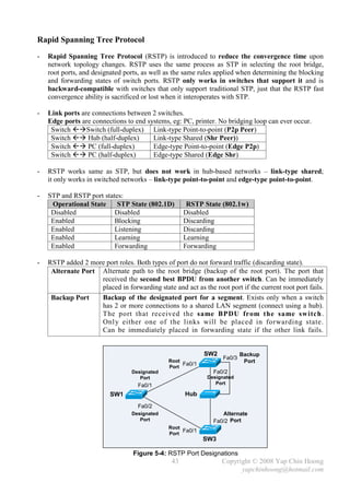
SW2#sh spanning-tree
VLAN0001
Spanning tree enabled protocol ieee
Root ID Priority 32768
Address aaaa.aaaa.aaaa
Cost 19
Port 1 (FastEthernet0/1)
Hello Time 2 sec Max Age 20 sec Forward Delay 15 sec
Bridge ID Priority 32769 (priority 32768 sys-id-ext 1)
Address bbbb.bbbb.bbbb
Hello Time 2 sec Max Age 20 sec Forward Delay 15 sec
Aging Time 300
Interface Role Sts Cost Prio.Nbr Type
---------------- ---- --- --------- -------- -------------------------------
Fa0/1 Root FWD 19 128.1 P2p
Fa0/2 Altn BLK 19 128.2 P2p
SW2#debug spanning-tree events
Spanning Tree event debugging is on
SW2#
SW2#conf t
Enter configuration commands, one per line. End with CNTL/Z.
SW2(config)#int fa0/2
SW2(config-if)#spanning-tree cost 10
SW2(config-if)#^Z
SW2#
47 Copyright © 2008 Yap Chin Hoong
yapchinhoong@hotmail.com](https://image.slidesharecdn.com/ccna2ndedition-12877133651663-phpapp02/85/Ccna-2nd-Edition-50-320.jpg)
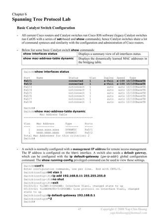
![EtherChannel Configuration
- In this section, both the trunks between SW1 and SW2 are configured as an EtherChannel.
- The channel-group [channel-group-number] mode on interface subcommand configures
an interface as an EtherChannel interface and assigns it to an EtherChannel channel group.
- Below shows the other 2 EtherChannel modes that allow a switch to automatically negotiate
with its neighboring switch in establishing an EtherChannel.
auto If configured on both switch ports, an EtherChannel will never be established.
desirable As long as one of the switch ports is configured with this mode, an EtherChannel
will be established.
- EtherChannel configuration on SW2:
SW2#conf t
Enter configuration commands, one per line. End with CNTL/Z.
SW2(config)#int fa0/1
SW2(config-if)#channel-group 1 mode on
SW2(config-if)#
00:40:00: %LINK-3-UPDOWN: Interface Port-channel1, changed state to up
00:40:01: %LINEPROTO-5-UPDOWN: Line protocol on Interface Port-channel1,
changed state to up
SW2(config-if)#int fa0/2
SW2(config-if)#channel-group 1 mode on
SW2(config-if)#^Z
SW2#sh spanning-tree
VLAN0001
Spanning tree enabled protocol ieee
Root ID Priority 24577
Address bbbb.bbbb.bbbb
This bridge is the root
Hello Time 2 sec Max Age 20 sec Forward Delay 15 sec
Bridge ID Priority 24577 (priority 24576 sys-id-ext 1)
Address bbbb.bbbb.bbbb
Hello Time 2 sec Max Age 20 sec Forward Delay 15 sec
Aging Time 15
Interface Role Sts Cost Prio.Nbr Type
---------------- ---- --- --------- -------- -------------------------------
Po1 Desg FWD 12 128.65 P2p
SW2#sh etherchannel 1 summary
Flags: D - down P - in port-channel
I - stand-alone s - suspended
R - Layer3 S - Layer2
u - unsuitable for bundling
U – port-channel in use
d - default port
Group Port-channel Protocol Ports
------+-------------+-----------+-------------------------------------------
1 Po1(SU) - Fa0/1(P) Fa0/2(P)
SW2#
49 Copyright © 2008 Yap Chin Hoong
yapchinhoong@hotmail.com](https://image.slidesharecdn.com/ccna2ndedition-12877133651663-phpapp02/85/Ccna-2nd-Edition-52-320.jpg)

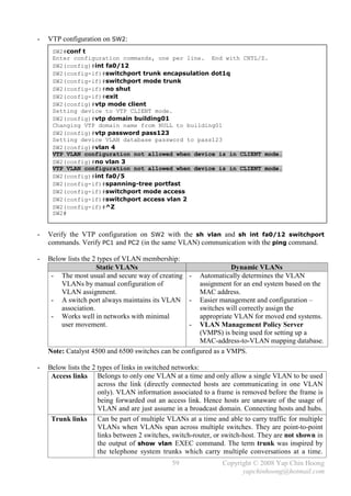
![- VTP Pruning provides a way to preserve bandwidth by configuring switches to only send
broadcasts and unknown unicasts to the trunks to other switches that need the information
(contain ports in a particular VLAN). VTP pruning is disabled by default, which means
broadcasts and unknown unicasts in every VLAN is forwarded to all switches in the network.
Ex: SW1 does not have any ports configured for VLAN 2, thus broadcasts sent to VLAN 2
should not be forwarded to the trunk to SW1 (pruning flooded traffic to conserve bandwidth).
Note: VLAN 1 can never be pruned because it is an administrative VLAN.
- The [no] vtp pruning privileged or global configuration command is used to enable or disable
VTP pruning respectively. VTP pruning only need to be enabled on a single VTP server mode
switch throughout a VTP domain. VTP pruning utilizes VLAN advertisements for its operation.
- Note: VTP pruning requires all switches in the VTP domain to be configured in server mode,
which can create havoc if multiple administrators are making VLAN changes on multiple server
switches at the same time.
- When PVST is in use, STP optimization for each VLAN and VTP pruning are important to
ensure STP changes that occur in a particular VLAN will not affect other STP instances for other
VLANs, which results in a more stable network.
56 Copyright © 2008 Yap Chin Hoong
yapchinhoong@hotmail.com](https://image.slidesharecdn.com/ccna2ndedition-12877133651663-phpapp02/85/Ccna-2nd-Edition-59-320.jpg)
![Chapter 9
IP Addressing and Subnetting
- 4 bits – nibble. 8 bits – byte / octet. The values in a byte are 128 64 32 16 8 4 2 1.
- Binary to Decimal memorization chart: Decimal to Binary to Hex chart:
Binary Value Decimal Value Decimal Binary Hexadecimal
10000000 128 1 0001 1
11000000 192 2 0010 2
11100000 224 3 0011 3
11110000 240 4 0100 4
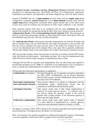
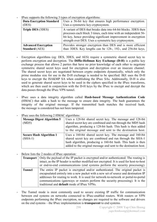
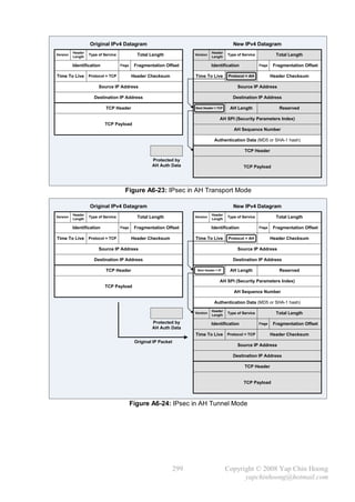
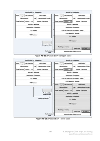
11111000 248 5 0101 5
11111100 252 6 0110 6
11111110 254 7 0111 7
11111111 255 8 1000 8
9 1001 9
10 1010 A
11 1011 B
12 1100 C
13 1101 D
14 1110 E
15 1111 F
- IP addresses are normally written in dotted-decimal format, eg: 192.168.0.100, 172.16.10.10.
- An IP address can be divided into 2 portions:
Network address that is used to identify the network.
Host address or node address that is used to identify the end system on the network.
- 5 different classes of IP address were designed for efficient routing by defining different
leading-bits sections for the address of different class. A router is able to identify an IP address
quickly by only reading the first few bits of the address, eg: if the address starts with 0,
it is a Class A address, etc. Classful routing protocols also use the first octet rule to determine
the class of an address when assigning subnet masks for their routing operation.
Valid Network Default Max number Max number
Class First Octet Range
Numbers Subnet Mask of networks of hosts
A 00000000 – 0 1.0.0.0 – 8 bits, 27 – 2, 24
2 – 2,
01111111 – 127 126.0.0.0 255.0.0.0 126 16777214
B 10000000 – 128 128.0.0.0 – 16 bits, 214, [1] 216 – 2,
10111111 – 191 191.255.0.0 255.255.0.0 16384 65534
C 11000000 – 192 192.0.0.0 – 24 bits, 221, [2] 28 – 2,
11011111 – 223 223.255.255.0 255.255.255.0 2097152 254
D [3] 11100000 – 224 224.0.0.0 – – – –
11101111 – 239 239.255.255.255
[4]
E 11110000 – 240 240.0.0.0 – – – –
11111111 – 255 255.255.255.255
[1] 14 = 6 bits in 1st octet + 8 bits in 2nd octet.
[2] 21 = 5 bits in 1st octet + 8 bits in 2nd octet + 8 bits in 3rd octet.
[3] Class D addresses are used for multicasting.
[4] Class E addresses are reserved for experimental and testing purposes.
61 Copyright © 2008 Yap Chin Hoong
yapchinhoong@hotmail.com](https://image.slidesharecdn.com/ccna2ndedition-12877133651663-phpapp02/85/Ccna-2nd-Edition-64-320.jpg)
![- The Boolean AND operation:
1st Bit 2nd Bit Operation Result
0 0 AND 0
0 1 AND 0
1 0 AND 0
1 1 AND 1
- The bitwise Boolean AND operation between an IP address and its subnet mask is used to
discover the subnet number for the IP address.
- First address Add 1 to the 4th octet of the subnet number.
Broadcast address Change the values of all host bits in the subnet number to binary 1s.
Last address (or largest valid IP address) Broadcast address – 1.
- Example 1: 10.0.0.1/16
IP Address 10.0.0.1 00001010 00000000 00000000 00000001
Subnet Mask 255.255.0.0 11111111 11111111 00000000 00000000
Subnet Number 10.0.0.0 00001010 00000000 00000000 00000000
First Address 10.0.0.1 00001010 00000000 00000000 00000001
Broadcast Address 10.0.255.255 00001010 00000000 11111111 11111111
Last Address 10.0.255.254 00001010 00000000 11111111 11111110
- Example 2: 172.16.0.1/24
IP Address 172.16.0.1 10101100 00010000 00000000 00000001
Subnet Mask 255.255.255.0 11111111 11111111 11111111 00000000
Subnet Number 172.16.0.0 10101100 00010000 00000000 00000000
First Address 172.16.0.1 10101100 00010000 00000000 00000001
Broadcast Address 172.16.0.255 10101100 00010000 00000000 11111111
Last Address 172.16.0.254 10101100 00010000 00000000 11111110
- Example 3: 192.168.100.100/28
IP Address 192.168.100.100 11000000 10101000 01100100 01100100
Subnet Mask 255.255.255.240 11111111 11111111 11111111 11110000
Subnet Number 192.168.100.96 11000000 10101000 01100100 01100000
First Address 192.168.100.97 11000000 10101000 01100100 01100001
Broadcast Address 192.168.100.111 11000000 10101000 01100100 01101111
Last Address 192.168.100.110 11000000 10101000 01100100 01101110
- Total number of subnets 2n – 2, where n is the number of subnet bits. [1]
Total number of hosts 2n – 2, where n is the number of host bits. [2]
[1] minus the subnet zero and the broadcast subnet.
[2] minus the network address (all-0s bit pattern) and the broadcast address (all-1s bit pattern).
Subnet zero It has all binary 0s in the subnet portion. Also known as all-0s subnet.
Broadcast subnet It has all binary 1s in the subnet portion. Also known as all-1s subnet.
- Ex: In 172.16.0.0, 255.255.255.0, 8 bits are borrowed from the 16 host bits for subnet bits.
With these 8 subnet bits, there are 2 8 – 2 = 254 subnets, and each subnet has 8 host bit,
which are 28 – 2 = 254 hosts are available on each subnet.
63 Copyright © 2008 Yap Chin Hoong
yapchinhoong@hotmail.com](https://image.slidesharecdn.com/ccna2ndedition-12877133651663-phpapp02/85/Ccna-2nd-Edition-66-320.jpg)

![Chapter 10
Managing a Cisco Internetwork
Resolving Hostnames
- By properly setting up hostname resolution or translation service, a hostname instead of an IP
address can be used to communicate with a device.
- Below lists the 2 available methods used to resolve hostnames to IP addresses:
i) Build a host table on each device (static host table).
ii) Setup a Domain Name System (DNS) server (dynamic host table).
- Below lists some Cisco IOS IP naming services commands:
ip domain-name {name} Defines the default domain name of a device.
Global configuration command.
ip domain-lookup Tells the IOS to resolve unknown hostnames and wrongly typed
commands using DNS. Global configuration command.
ip name-server {svr1} Configures the DNS name server IP addresses (max of 6).
[svr2… svr6] Global configuration command.
ip host {name} {ip-addr} Creates a static entry in the host table.
Global configuration command.
no ip host {name} Removes a static entry from the host table.
Global configuration command.
show hosts Lists DNS and host table information. EXEC command.
Switch#conf t
Switch(config)#ip host router01 192.168.0.1
Switch(config)#ip host router02 192.168.0.2
Switch(config)#ip name-server 172.16.0.1 172.16.0.2
Switch(config)#^Z
Switch#
Switch#sh hosts
Default domain is not set
Name/address lookup uses domain service
Name servers are 172.16.0.3, 172.16.1.3
Codes: u - unknown, e - expired, * - OK, ? - revalidate
t - temporary, p - permanent
Host Port Flags Age Type Address(es)
router01 None (perm, OK) 0 IP 192.168.0.1
router02 None (perm, OK) 0 IP 192.168.0.2
Switch#
Note: The perm in the Flags column represents a manually configured entry; while the temp
represents a cached DNS-resolved entry.
- It is recommended to have at least 2 name servers for redundancy and availability purposes.
67 Copyright © 2008 Yap Chin Hoong
yapchinhoong@hotmail.com](https://image.slidesharecdn.com/ccna2ndedition-12877133651663-phpapp02/85/Ccna-2nd-Edition-70-320.jpg)
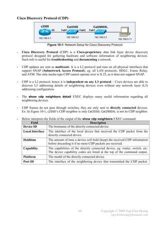
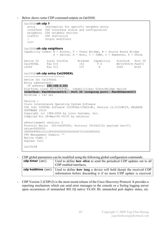
![- CDP is enabled by default.
The no cdp run global configuration command completely disables CDP on a device.
The no cdp enable interface subcommand disables CDP for an interface – stop sending out
and ignore CDP packets on the interface.
Cat3550#sh cdp int fa0/1
FastEthernet0/1 is up, line protocol is up
Encapsulation ARPA
Sending CDP packets every 60 seconds
Holdtime is 180 seconds
Cat3550#conf t
Enter configuration commands, one per line. End with CNTL/Z.
Cat3550(config)#cdp ?
advertise-v2 CDP sends version-2 advertisements
holdtime Specify the holdtime (in sec) to be sent in packets
run Enable CDP
timer Specify the rate at which CDP packets are sent (in sec)
Cat3550(config)#int fa0/1
Cat3550(config-if)#no cdp enable
Cat3550(config-if)#^Z
Cat3550#sh cdp int fa0/1
Cat3550#
Telnet
- Cisco IOS allows Telnet from a Cisco device to another Cisco device. An important feature of
the telnet EXEC command is the suspend feature.
- Lab setup: Setup the sample network as in Figure 10-1. Configure the hostname and IP address
on every device, and create a host table consisting static entries for all devices on every device.
- Below lists some Cisco IOS Telnet-related commands:
telnet {hostname | ip-addr} Used to Telnet from a device to another device.
show sessions or where Used to list the suspended telnet sessions.
resume {connection-id} Used to resume a suspended telnet session.
disconnect {connection-id} Used to terminate a suspended telnet session.
- A Telnet session can be suspended with the following key sequence:
Ctrl + Shift + 6, release, then x.
- In the show sessions or where EXEC commands output, an asterisk [*] will be shown at the
left of the most recently suspended Telnet session, which can be resumed by using the resume
EXEC command, or by pressing Enter or Tab in EXEC or privileged mode. Connection ID
is the identification for a Telnet session.
70 Copyright © 2008 Yap Chin Hoong
yapchinhoong@hotmail.com](https://image.slidesharecdn.com/ccna2ndedition-12877133651663-phpapp02/85/Ccna-2nd-Edition-73-320.jpg)
![- Below demonstrates the usage of Telnet suspension:
Cat3550>telnet Cat2900XL
Trying Cat2900XL (192.168.0.3)... Open
Cat2900XL>
Cat2900XL> [Ctrl+Shift+6, x]
Cat3550>telnet c2500
Trying c2500 (192.168.0.1)... Open
c2500>
c2500> [Ctrl+Shift+6, x]
Cat3550>sh sessions
Conn Host Address Byte Idle Conn Name
1 Cat2900XL 192.168.0.3 0 0 Cat2900XL
* 2 c2500 192.168.0.1 0 0 c2500
Cat3550> [Enter]
[Resuming connection 2 to c2500 ... ]
c2500> [Ctrl+Shift+6, x]
Cat3550>resume 1
[Resuming connection 1 to Cat2900XL ... ]
Cat2900XL> [Ctrl+Shift+6, x]
Cat3550>where
Conn Host Address Byte Idle Conn Name
* 1 Cat2900XL 192.168.0.3 0 0 Cat2900XL
2 c2500 192.168.0.1 0 0 c2500
Cat3550>disconnect 1
Closing connection to Cat2900XL [confirm] [Enter]
Cat3550> [Enter]
[Resuming connection 2 to c2500 ... ]
c2500> [Ctrl+Shift+6, x]
Cat3550>where
Conn Host Address Byte Idle Conn Name
* 2 c2500 192.168.0.1 0 0 c2500
Cat3550> [Enter]
[Resuming connection 2 to c2500 ... ]
c2500>
c2500>exit
[Connection to c2500 closed by foreign host]
Cat3550>
Cat3550>where
% No connections open
Cat3550>
71 Copyright © 2008 Yap Chin Hoong
yapchinhoong@hotmail.com](https://image.slidesharecdn.com/ccna2ndedition-12877133651663-phpapp02/85/Ccna-2nd-Edition-74-320.jpg)
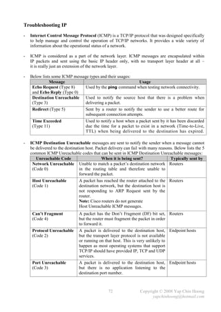
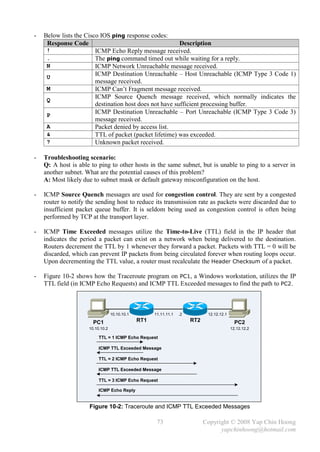
![- Tips: The show controllers {intf-type intf-num} EXEC command can be used to find out
which end (DTE or DCE) is plugged into a serial interface:
Router#show controllers serial 0/0
HD unit 0, idb = 0xC2518, driver structure at 0xC79B0
buffer size 1524 HD unit 0, V.35 DCE cable
cpb = 0xE1, eda = 0x4940, cda = 0x4800
RX ring with 16 entries at 0xE14800
- The terminal ip netmask-format {bit-count | decimal} EXEC command can be used to
change the network mask format (prefix notation – /xx or dotted decimal – x.x.x.x)
in the output of the series of show command, eg: show ip route.
- Troubleshooting network problems with ping:
Error Message Possible Cause
Destination host unreachable Packet dropped on the way to the destination.
Normally returned by an intermediate router when it is not able
to find a route to the destination network.
Request timed out Packet dropped on the way to the destination.
Another possible cause is an intermediate router does not have a
route to the network of the source host when the packet is on
the way back from the destination network.
Static Routing Configuration
- Currently, a Request timed out error message would be received when trying to ping
192.168.2.2 from PC1. This is due to RT2 does not have a route to 192.168.1.0/24 network!
This section shows the static routing configuration on all routers for them to reach all networks.
- The ip route {destination-network} {subnet-mask} {next-hop-addr | outgoing-intf}
[administrative-distance] [permanent] global configuration command defines static routes.
Note: Static routes that use the outgoing interface option instead of the next-hop address option
are considered as directly connected static routes.
Note: Only configure static routes pointing to an outgoing interface on point-to-point links,
as the router won’t be able to resolve a next-hop address in point-to-multipoint topologies.
- Static Routing configuration on RT1:
RT1(config)#ip route 192.168.3.0 255.255.255.0 192.168.2.2
RT1(config)#ip route 192.168.4.0 255.255.255.0 192.168.2.2
RT1(config)#ip route 192.168.5.0 255.255.255.0 192.168.2.2
RT1(config)#^Z
RT1#
RT1#sh ip route
Gateway of last resort is not set
C 192.168.1.0/24 is directly connected, FastEthernet1/0
C 192.168.2.0/24 is directly connected, Serial0/0
S 192.168.3.0/24 [1/0] via 192.168.2.2
S 192.168.4.0/24 [1/0] via 192.168.2.2
S 192.168.5.0/24 [1/0] via 192.168.2.2
83 Copyright © 2008 Yap Chin Hoong
yapchinhoong@hotmail.com](https://image.slidesharecdn.com/ccna2ndedition-12877133651663-phpapp02/85/Ccna-2nd-Edition-86-320.jpg)
![- Static Routing configuration on RT2:
RT2(config)#ip route 192.168.1.0 255.255.255.0 192.168.2.1
RT2(config)#ip route 192.168.5.0 255.255.255.0 192.168.4.2
RT2(config)#^Z
RT2#
- Static Routing configuration on RT3:
RT3(config)#ip route 192.168.1.0 255.255.255.0 192.168.4.1
RT3(config)#ip route 192.168.2.0 255.255.255.0 192.168.4.1
RT3(config)#ip route 192.168.3.0 255.255.255.0 192.168.4.1
RT3(config)#^Z
RT3#
- The values in the bracket [x/y] of the routes shown in the show ip route EXEC command
represent the administrative distance and metric respectively.
Default Routing Configuration
- Default routing is very useful in situations where learning all the more specific networks is
not desirable or not feasible due to limited system resources, eg: memory, processing power.
Packets destined to networks that are not in the routing table – unknown destination networks
will be directed to the default route. A default route is also known as the gateway of last resort.
- Default routing can only be used on stub networks – networks with only one entry and exit
point to all outside networks. RT1 and RT3 are considered in stub networks.
- Default routes can be configured by substituting the destination network and subnet mask with
wildcards (0.0.0.0) in the ip route static routing configuration command.
- Default Routing configuration on RT1:
RT1(config)#no ip route 192.168.3.0 255.255.255.0
RT1(config)#no ip route 192.168.4.0 255.255.255.0
RT1(config)#no ip route 192.168.5.0 255.255.255.0
RT1(config)#ip route 0.0.0.0 0.0.0.0 192.168.2.2
RT1(config)#^Z
RT1#
RT1#sh ip route
Codes: C - connected, S - static, I - IGRP, R - RIP, M - mobile, B - BGP
D - EIGRP, EX - EIGRP external, O - OSPF, IA - OSPF inter area
E1 - OSPF external type 1, E2 - OSPF external type 2, E – EGP
Gateway of last resort is 192.168.2.2 to network 0.0.0.0
C 192.168.1.0/24 is directly connected, FastEthernet1/0
C 192.168.2.0/24 is directly connected, Serial0/0
S* 0.0.0.0/0 [1/0] via 192.168.2.2
RT1#
- Notice the Gateway of last resort in the routing table. An asterisk (*) indicates a default route.
84 Copyright © 2008 Yap Chin Hoong
yapchinhoong@hotmail.com](https://image.slidesharecdn.com/ccna2ndedition-12877133651663-phpapp02/85/Ccna-2nd-Edition-87-320.jpg)
![- RIPv1 and IGRP are classful routing protocols and therefore use classful network addresses in
their configuration, which means that they must consider which class an interface resides in
(Class A, B, or C network) when performing tasks. Classful routing protocols do not send
subnet mask information along routing updates as they assume that all hosts and router
interfaces connected to all segments throughout the network belongs to the same classful
network and use the same subnet mask! RIPv1 and IGRP, which are distance-vector classful
routing protocols, do not support VLSM and route summarization. Note: RIPv2 supports VLSM.
- The network {classful-network-addr} router subcommand is able to figure out the IP
address class of the network address that is entered along with the command (similar to the IP
address configuration dialog in Microsoft Windows). The command will change the network
number entered along with the command to its classful entry or the major network number.
Ex: 10.1.1.0 10.0.0.0; 172.16.1.0 172.16.0.0.
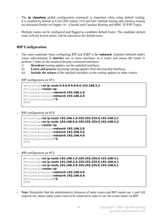
- Verify the RIP configuration on RT1, RT2 and RT3 with the show ip route EXEC command:
RT1#show ip route
Gateway of last resort is not set
C 192.168.1.0/24 is directly connected, FastEthernet1/0
C 192.168.2.0/24 is directly connected, Serial0/0
R 192.168.3.0/24 [120/1] via 192.168.2.2, 00:00:10, Serial0/0
R 192.168.4.0/24 [120/1] via 192.168.2.2, 00:00:10, Serial0/0
R 192.168.5.0/24 [120/2] via 192.168.2.2, 00:00:10, Serial0/0
RT1#
- The show ip protocols EXEC command provides an overview of all running routing
protocols when multiple routing protocols are running on a single router. It also displays other
routers that sending routing updates to the router, and all the timer values used for the operation
of the routing protocols.
RT2#sh ip protocols
Routing Protocol is "rip"
Sending updates every 30 seconds, next due in 18 seconds
Invalid after 180 seconds, hold down 180, flushed after 240
Outgoing update filter list for all interfaces is not set
Incoming update filter list for all interfaces is not set
Redistributing: rip
Default version control: send version 1, receive any version
Interface Send Recv Triggered RIP Key-chain
FastEthernet1/0 1 1 2
Serial0/0 1 1 2
Serial0/1 1 1 2
Automatic network summarization is in effect
Maximum path: 4
Routing for Networks:
192.168.2.0
192.168.3.0
192.168.4.0
Routing Information Sources:
Gateway Distance Last Update
192.168.2.1 120 00:00:10
192.168.4.2 120 00:00:05
Distance: (default is 120)
RT2#
86 Copyright © 2008 Yap Chin Hoong
yapchinhoong@hotmail.com](https://image.slidesharecdn.com/ccna2ndedition-12877133651663-phpapp02/85/Ccna-2nd-Edition-89-320.jpg)
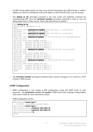
![- IGRP configuration on RT2:
RT2(config)#router igrp 1
RT2(config-router)#network 192.168.2.0
RT2(config-router)#network 192.168.3.0
RT2(config-router)#network 192.168.4.0
RT2(config-router)#^Z
RT2#
- IGRP configuration on RT3:
RT3(config)#router igrp 1
RT3(config-router)#network 192.168.4.0
RT3(config-router)#network 192.168.5.0
RT3(config-router)#^Z
RT3#
- Verify the IGRP configuration on RT1, RT2 and RT3.
RT1#show ip route
Gateway of last resort is not set
C 192.168.1.0 is directly connected, FastEthernet1/0
C 192.168.2.0 is directly connected, Serial0/0
I 192.168.3.0 [100/8486] via 192.168.2.2, 00:00:09, Serial0/0
I 192.168.4.0 [100/10476] via 192.168.2.2, 00:00:09, Serial0/0
I 192.168.5.0 [100/10486] via 192.168.2.2, 00:00:09, Serial0/0
RT1#
- Q: If RIP and IGRP are running at the same time, routes from which protocol will be selected?
A: IGRP has a lower administrative distance value than RIP; hence IGRP routes will be selected.
Anyway, take note that if RIP is still running in the background, it can consume unnecessary
router CPU resources and network bandwidth.
- The information after the next hop IP address for a route indicates the invalid timer for a route
in hh:mm:ss format. The timer is reset to all 0s upon an update for a particular route is received.
When the invalid timer for a route is expired, the route will be marked as possibly down and the
router will start the holddown cycle for the particular route.
- A router will still use routes in holddown state when forward packets destined to the network.
This is a standard behavior of many IP routing protocols, which is based on the assumption that
temporary packet loss due to using routes to networks that might not be viable is better
than immediately accepting a less desirable route to the destination network.
- DV routing protocols do not support discontiguous networks. When a router running RIP or
IGRP receives a route, it checks if the routing update information contains the same major
network number that is configured on the receiving interface. If it does, it applies the subnet
mask that is configured on the receiving interface to the newly received route; else if it doesn’t
(the routing update information contains a different major network number than the receiving
interface), it applies the default classful subnet mask accordingly.
Ex: A router receives a route to 172.16.2.0 from an interface 172.16.1.1/24, it applies the /24
mask to the route and becomes 172.16.2.0/24. Else, it applies the default /16 mask to the route
and becomes 172.16.0.0/16.
88 Copyright © 2008 Yap Chin Hoong
yapchinhoong@hotmail.com](https://image.slidesharecdn.com/ccna2ndedition-12877133651663-phpapp02/85/Ccna-2nd-Edition-91-320.jpg)
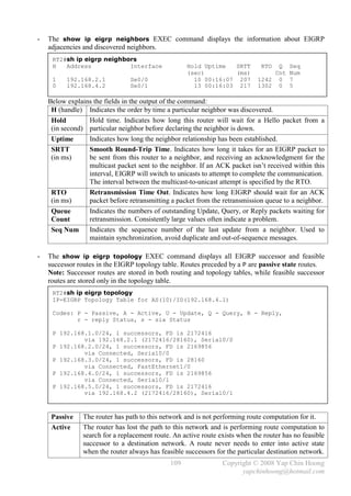
![- Autosummarization EIGRP supports route summarization, which is commonly used to
reduce the size of routing tables. However, EIGRP performs autosummarization by default,
which means routes belong to the classful networks different than the classful network of the
interface that sends out the routing updates (routing updates cross 2 major networks) will be
summarized as a single summary route up to the classful network boundary of the addresses.
Figure 13-4 shows a discontiguous network with autosummarization, which would never work!
RIP, RIPv2, and IGRP also perform autosummarization by default, except OSPF.
The autosummarization feature can be disabled. The best practice is disable autosummarization
with the no auto-summary router subcommand and performs manual route summarization
with the ip summary-address interface subcommand when necessary.
Classful network boundary: 172.16.10.0/24 172.16.0.0/16. 10.1.1.0/24 10.0.0.0/8.
172.16.10.0/24 172.16.20.0/24
10.1.1.0/24
Network 172.16.0.0 Network 172.16.0.0
is over here! is over here!
Figure 13-4: EIGRP Autosummarization
- Figure 13-4 shows 2 EIGRP routers advertise the same network – 172.16.0.0/16, which in fact
they should advertise 2 different networks – 172.16.10.0/24 and 172.16.20.0/24.
- RIPv2 and EIGRP do not support discontiguous networks by default due to autosummarization;
OSPF supports discontiguous networks by default as it does not perform autosummarization.
- The EIGRP automatic redistribution feature eases IGRP to EIGRP routing protocol migration.
Introduce a router to reside between the IGRP and EIGRP domains which runs IGRP and EIGRP
concurrently, and configure all EIGRP routers with the same AS number of IGRP domain.
EIGRP will automatically redistribute IGRP routes into EIGRP (as external routes, AD 170).
Note: However, EIGRP routes are not automatically distributed into the IGRP domain.
- Comparison between Distance-Vector, Link-State, and Balanced Hybrid routing protocols:
Distance-Vector Uses Bellman-Ford algorithm for route computation. Each router sends all
its routing table entries (large updates) only to neighboring routers. [1]
Link-State Uses Shortest Path First algorithm for route computations. Each router
sends only a portion of its routing table (small partial updates) that
describes its link status (up/down, cost) to all routers within an area. [1]
LS protocols flood routing updates to all routers within an area. [2]
Balanced Hybrid Have attributes associated with both DV and LS protocols – uses the
routing-by-rumor mechanism (DV feature) and uses the Hello packets in
neighbor discovery and maintenance (LS feature). Balanced Hybrid
protocols send small updates only to neighboring routers. [2]
[1] and [2] are comparison points between DV and LS protocols, as well as between LS and BH
protocols respectively.
- For environments with routers from various vendors, use OSPF. For environments with only
Cisco routers, use EIGRP.
98 Copyright © 2008 Yap Chin Hoong
yapchinhoong@hotmail.com](https://image.slidesharecdn.com/ccna2ndedition-12877133651663-phpapp02/85/Ccna-2nd-Edition-101-320.jpg)
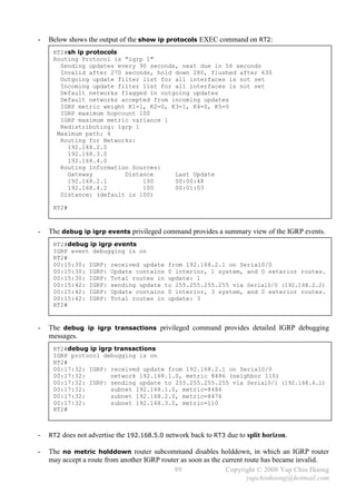
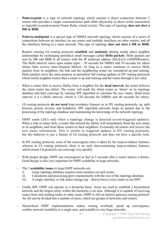
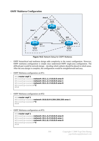
![- OSPF Single-Area configuration on RT3:
RT3(config)#router ospf 1
RT3(config-router)#network 10.1.3.2 0.0.0.0 area 0
RT3(config-router)#network 10.1.5.2 0.0.0.0 area 0
RT3(config-router)#network 10.1.6.1 0.0.0.0 area 0
RT3(config-router)#^Z
RT3#
- The network {ip-addr} {wildcard-mask} area {area-id} router subcommand identifies the
interfaces that belong to an OSPF process, the interfaces to transmit and receive routing updates,
the OSPF area that the interfaces reside on, and the networks to be included in the routing updates.
- OSPF network router subcommand differs from RIP and IGRP network router subcommands
in its way of matching interfaces. It includes a parameter called the wildcard mask. Binary 1s in
the wildcard mask are considered wildcard bits or don’t care bits, means that the router does not
need to care what binary value is in the corresponding bits. Wildcard masks are also used in
access control list configuration.
- Binary 0s in the wildcard mask indicates that the corresponding bits of an interface IP address
must be matched exactly. Ex: 1.1.1.1 and 0.0.0.0 would match 1.1.1.1 only. 1.1.0.0 and
0.0.255.255 would match anything in the range 1.1.0.0 – 1.1.255.255. It is often simpler
and safer to use the 0.0.0.0 wildcard mask to identify each OSPF interface individually.
- Verify the OSPF Single-Area configuration on RT1:
RT1#sh ip route
Gateway of last resort is not set
10.0.0.0/24 is subnetted, 6 subnets
C 10.1.1.0 is directly connected, FastEthernet1/0
C 10.1.2.0 is directly connected, Serial0/0
C 10.1.3.0 is directly connected, Serial0/1
O 10.1.4.0 [110/65] via 10.1.2.2, 00:00:32, Serial0/0
O 10.1.5.0 [110/128] via 10.1.2.2, 00:00:32, Serial0/0
[110/128] via 10.1.3.2, 00:00:32, Serial0/1
O 10.1.6.0 [110/65] via 10.1.3.2, 00:00:32, Seria0/1
RT1#
- Verify the OSPF Single-Area configuration on RT2:
RT2#sh ip route
Gateway of last resort is not set
10.0.0.0/24 is subnetted, 6 subnets
O 10.1.1.0 [110/65] via 10.1.2.1, 00:00:48, Serial0/0
C 10.1.2.0 is directly connected, Serial0/0
O 10.1.3.0 [110/128] via 10.1.2.1, 00:00:48, Serial0/0
[110/128] via 10.1.5.2, 00:00:48, Serial0/1
C 10.1.4.0 is directly connected, FastEthernet1/0
C 10.1.5.0 is directly connected, Serial0/1
O 10.1.6.0 [110/65] via 10.1.5.2, 00:00:48, Serial0/1
RT2#
100 Copyright © 2008 Yap Chin Hoong
yapchinhoong@hotmail.com](https://image.slidesharecdn.com/ccna2ndedition-12877133651663-phpapp02/85/Ccna-2nd-Edition-103-320.jpg)
![- Verify the OSPF Single-Area configuration on RT3:
RT3#sh ip route
Gateway of last resort is not set
10.0.0.0/24 is subnetted, 6 subnets
O 10.1.1.0 [110/65] via 10.1.3.1, 00:01:09, Serial0/0
O 10.1.2.0 [110/128] via 10.1.3.1, 00:01:09, Serial0/0
[110/128] via 10.1.5.1, 00:01:09, Serial0/1
C 10.1.3.0 is directly connected, Serial0/0
O 10.1.4.0 [110/65] via 10.1.5.1, 00:01:09, Serial0/1
C 10.1.5.0 is directly connected, Serial0/1
C 10.1.6.0 is directly connected, FastEthernet1/0
RT3#
MISC OSPF Commands
- The show ip route ospf EXEC command displays only OSPF routes in the routing table.
RT1#sh ip route ospf
10.0.0.0/24 is subnetted, 3 subnets
O 10.1.4.0 [110/65] via 10.1.2.2, 00:02:01, Serial0/0
O 10.1.5.0 [110/128] via 10.1.2.2, 00:02:01, Serial0/0
[110/128] via 10.1.3.2, 00:02:01, Serial0/1
O 10.1.6.0 [110/65] via 10.1.3.2, 00:02:01, Serial0/1
RT1#
- The show ip ospf EXEC command displays OSPF information for all OSPF processes running
on a router, eg: Router ID, area information, SPF statistics, LSA timer information, etc.
Notice that the RID on RT1 is 10.1.3.1, which is the highest IP address (physical) of the router.
RT1#sh ip ospf
Routing Process "ospf 1" with ID 10.1.3.1
Supports only single TOS(TOS0) routes
Supports opaque LSA
SPF schedule delay 5 secs, Hold time between two SPFs 10 secs
Minimum LSA interval 5 secs. Minimum LSA arrival 1 secs
Number of external LSA 0. Checksum Sum 0x0
Number of opaque AS LSA 0. Checksum Sum 0x0
Number of DCbitless external and opaque AS LSA 0
Number of DoNotAge external and opaque AS LSA 0
Number of areas in this router is 1. 1 normal 0 stub 0 nssa
External flood list length 0
Area BACKBONE(0)
Number of interfaces in this area is 3
Area has no authentication
SPF algorithm last executed 00:03:10 ago
SPF algorithm executed 3 times
Area ranges are
Number of LSA 3. Checksum Sum 0x015FCD
Number of opaque link LSA 0. Checksum Sum 0x0
Number of DCbitless LSA 0
Number of indication LSA 0
Number of DoNotAge LSA 0
Flood list length 0
RT1#
101 Copyright © 2008 Yap Chin Hoong
yapchinhoong@hotmail.com](https://image.slidesharecdn.com/ccna2ndedition-12877133651663-phpapp02/85/Ccna-2nd-Edition-104-320.jpg)
![- The show ip ospf database EXEC command displays the OSPF topology database, which
contains the number of routers in the autonomous system and the RID of the neighboring router.
It shows the Router ID (Link ID), the RID of the advertising router (ADV Router), the version of
the OSPF database which used to detect old or duplicate LSUs ( Seq#), and the number of links
(including point-to-point links, transit links, stub networks, and virtual links) detected for a
particular router (Link count). The output is broken down by the OSPF processes and areas.
RT1#sh ip ospf database
OSPF Router with ID (10.1.3.1) (Process ID 1)
Router Link States (Area 0)
Link ID ADV Router Age Seq# Checksum Link count
10.1.3.1 10.1.3.1 170 0x80000003 0x00234A 5
10.1.5.1 10.1.5.1 172 0x80000003 0x0066FC 5
10.1.6.1 10.1.6.1 169 0x80000003 0x00D587 5
RT1#
- The show ip ospf interface [intf-type intf-num] EXEC command displays all interface-
related OSPF information for all interfaces or a particular interface. It shows the interface state,
interface IP address, area assignment, Process ID, Router ID, network type, cost, priority,
DR/BDR election information (if applicable), timer intervals, adjacent neighbor information,
and authentication configuration information (if applicable).
RT1#sh ip ospf interface
FastEthernet1/0 is up, line protocol is up
Internet Address 10.1.1.1/24, Area 0
Process ID 1, Router ID 10.1.3.1, Network Type BROADCAST, Cost: 1
Transmit Delay is 1 sec, State DR, Priority 1
Designated Router (ID) 10.1.3.1, Interface address 10.1.1.1
No backup designated router on this network
Timer intervals configured, Hello 10, Dead 40, Wait 40, Retransmit 5
Hello due in 00:00:00
Index 1/1, flood queue length 0
Next 0x0(0)/0x0(0)
Last flood scan length is 0, maximum is 0
Last flood scan time is 0 msec, maximum is 0 msec
Neighbor Count is 0, Adjacent neighbor count is 0
Suppress hello for 0 neighbor(s)
--- output omitted ---
- The show ip ospf neighbor [intf-type intf-num] [neighbor-id] [detail] EXEC command is a
very useful command because it summarizes the important OSPF information regarding
neighbors and the adjacency state, as well as the DR/BDR information (only if applicable, as DR
and BDR are not used on point-to-point and point-to-multipoint interfaces) for all interfaces or a
particular interface. The neighbors are identified with their Router IDs (highest IP address).
RT1#sh ip ospf neighbor
Neighbor ID Pri State Dead Time Address Interface
10.1.5.1 1 FULL/ - 00:00:29 10.1.2.2 Serial0/0
10.1.6.1 1 FULL/ - 00:00:35 10.1.3.2 Serial0/1
RT1#
102 Copyright © 2008 Yap Chin Hoong
yapchinhoong@hotmail.com](https://image.slidesharecdn.com/ccna2ndedition-12877133651663-phpapp02/85/Ccna-2nd-Edition-105-320.jpg)
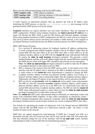
![- RT1 and RT3 cannot match all their 3 interfaces with a single network router subcommand,
as both routers have an interface that resides in a different area than the other 2 interfaces.
However, this is possible for RT2 since all its interfaces are in the same area.
- Verify the OSPF Multiarea configuration on RT1:
RT1#sh ip route
Gateway of last resort is not set
10.0.0.0/24 is subnetted, 6 subnets
C 10.1.1.0 is directly connected, FastEthernet10
C 10.1.2.0 is directly connected, Serial0/0
C 10.1.3.0 is directly connected, Serial0/1
O 10.1.4.0 [110/65] via 10.1.2.2, 00:02:04, Serial0/0
O 10.1.5.0 [110/128] via 10.1.2.2, 00:02:04, Serial0/0
O 10.1.6.0 [110/65] via 10.1.3.2, 00:07:41, Serial0/1
RT1#
- Verify the OSPF Multiarea configuration on RT2:
RT2#sh ip route
Gateway of last resort is not set
10.0.0.0/24 is subnetted, 6 subnets
O IA 10.1.1.0 [110/65] via 10.1.2.1, 00:03:05, Serial0/0
C 10.1.2.0 is directly connected, Serial0/0
O IA 10.1.3.0 [110/128] via 10.1.2.1, 00:03:05, Serial0/0
[110/128] via 10.1.5.2, 00:03:05, Serial0/1
C 10.1.4.0 is directly connected, FastEthernet1/0
C 10.1.5.0 is directly connected, Serial0/1
O IA 10.1.6.0 [110/65] via 10.1.5.2, 00:03:05, Serial/01
RT2#
- Verify the OSPF Multiarea configuration on RT3:
RT3#sh ip route
Gateway of last resort is not set
10.0.0.0/24 is subnetted, 6 subnets
O 10.1.1.0 [110/74] via 10.1.3.1, 00:09:48, Serial0/0
O 10.1.2.0 [110/128] via 10.1.5.1, 00:04:11, Serial0/1
C 10.1.3.0 is directly connected, Serial0/0
O 10.1.4.0 [110/74] via 10.1.5.1, 00:04:11, Serial0/1
C 10.1.5.0 is directly connected, Serial/01
C 10.1.6.0 is directly connected, FastEthernet1/0
RT3#
- Note: The routes learned by RT2 from the other 2 routers are shown as OSPF interarea (IA)
routes, as those subnets are reside in Area 0, while RT2 resides in Area 1.
105 Copyright © 2008 Yap Chin Hoong
yapchinhoong@hotmail.com](https://image.slidesharecdn.com/ccna2ndedition-12877133651663-phpapp02/85/Ccna-2nd-Edition-108-320.jpg)
![- Verify the EIGRP configuration on RT1:
RT1#sh ip route
Gateway of last resort is not set
C 192.168.1.0/24 is directly connected, FastEthernet1/0
C 192.168.2.0/24 is directly connected, Serial0/0
D 192.168.3.0/24 [90/2172416] via 192.168.2.2, 00:04:41, Serial0/0
D 192.168.4.0/24 [90/2681856] via 192.168.2.2, 00:04:41, Serial0/0
D 192.168.5.0/24 [90/2684416] via 192.168.2.2, 00:04:41, Serial0/0
RT1#
- Verify the EIGRP configuration on RT2:
RT2#sh ip route
Gateway of last resort is not set
D 192.168.1.0/24 [90/2172416] via 192.168.2.1, 00:05:25, Serial0/0
C 192.168.2.0/24 is directly connected, Serial0/0
C 192.168.3.0/24 is directly connected, FastEthernet1/0
C 192.168.4.0/24 is directly connected, Serial0/1
D 192.168.5.0/24 [90/2172416] via 192.168.4.2, 00:05:25, Serial0/1
RT2#
- Verify the EIGRP configuration on RT3:
RT3#sh ip route
Gateway of last resort is not set
D 192.168.1.0/24 [90/2684416] via 192.168.4.1, 00:05:57, Serial0/0
D 192.168.2.0/24 [90/2681856] via 192.168.4.1, 00:05:58, Serial0/0
D 192.168.3.0/24 [90/2172416] via 192.168.4.1, 00:05:58, Serial0/0
C 192.168.4.0/24 is directly connected, Serial0/0
C 192.168.5.0/24 is directly connected, FastEthernet1/0
RT3#
- The show ip eigrp interfaces EXEC command displays the information about
EIGRP-enabled interfaces.
RT2#sh ip eigrp interfaces
IP-EIGRP interfaces for process 10
Xmit Queue Mean Pacing Time Multicast Pending
Interface Peers Un/Reliable SRTT Un/Reliable Flow Timer Routes
Se0/0 1 0/0 207 5/190 250 0
Se0/1 1 0/0 217 5/190 250 0
Fa1/0 1 0/0 1 0/10 50 0
RT2#
108 Copyright © 2008 Yap Chin Hoong
yapchinhoong@hotmail.com](https://image.slidesharecdn.com/ccna2ndedition-12877133651663-phpapp02/85/Ccna-2nd-Edition-111-320.jpg)
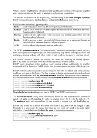
![Chapter 15
Variable-Length Subnet Masks and Route Summarization
Variable-Length Subnet Masks
- VLSM allows more than one subnet mask to be used within a single Class A, B, or C network.
VLSM allows the creation of efficient network addressing plan by using different subnet masks
for different networks – some subnets to be larger and some to be smaller, which is able to
reduce the wasted IP addresses in each subnet, and hence allows the creation of more subnets.
- A routing protocol that supports VLSM (eg: RIPv2, EIGRP, and OSPF) must be used for routers
to learn VLSM routes in a network. A routing protocol that supports VLSM advertises not only
the subnet number, but also the subnet mask along with its routing updates.
- The most efficient subnet mask for point-to-point links is 255.255.255.252 (/30).
It provides 1 network address, 2 host addresses, and 1 broadcast address, which is sufficient for
2 end systems on a point-to-point link.
- The following table shows the network addresses for the common subnet masks:
Mask Subnet Bits Host Bits Block Size Network Addresses
/24 0 8 256 addresses .0
/25 1 7 128 addresses .0, or .128
/26 2 6 64 addresses .0, .64, .128, or .192
/27 3 5 32 addresses .0, .32, .64, .96, .128, .160, .192, or .224
/28 4 4 16 addresses .0, .16, .32, … (multiplier of 16)
/29 5 3 8 addresses .0, .8, .16, … (multiplier of 8)
/30 6 2 4 addresses .0, .4, .8, … (multiplier of 4)
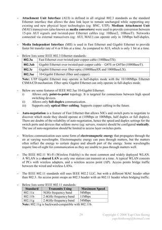
- Caution: Watch out for the subnets overlap issue when implementing VLSM networks.
RT1 10.1.2.0/30 RT2 10.1.3.0/30 RT3
10.2.1.0 10.3.4.0
10.2.2.0 S0/0 S0/0 10.3.5.0
10.2.3.0 S0/0 S0/1 10.3.6.0
10.2.4.0 10.3.7.0
10.2.0.0/16 10.3.0.0/16
10.1.1.0/24
Figure 15-1: Sample VLSM Network
- Below shows the routing table on RT2 in the sample VLSM network with 2 separate masks (/24
and /30) configured on interfaces, along with autosummarized EIGRP routes from other routers:
RT2#sh ip route
Gateway of last resort is not set
10.0.0.0/8 is variably subnetted, 5 subnets, 3 masks
D 10.2.0.0/16 [90/2195456] via 10.1.2.1, 00:00:07, Serial0/0
D 10.3.0.0/16 [90/2195456] via 10.1.3.2, 00:06:27, Serial0/1
C 10.1.1.0/24 is directly connected, Ethernet1/0
C 10.1.2.0/30 is directly connected, Serial0/0
C 10.1.3.0/30 is directly connected, Serial0/1
RT2#
Note: EIGRP autosummarization is enabled in this scenario.
111 Copyright © 2008 Yap Chin Hoong
yapchinhoong@hotmail.com](https://image.slidesharecdn.com/ccna2ndedition-12877133651663-phpapp02/85/Ccna-2nd-Edition-114-320.jpg)
![Route Summarization
- The larger the network, more routes to advertise, larger routing update packets, more bandwidth
the updates take, and hence reducing the bandwidth available for data transmission. Besides that,
large IP networks also produce large routing tables, which consume more router memory,
and take more time and CPU cycles to perform routing table lookup when routing a packet.
- Route summarization reduces the size of routing updates and tables while still maintain routing
information to all destination networks. It is also known as route aggregation or supernetting.
- Route summarization also able to reduce convergences. Upstream routers that received the
summary route do not have to reconverge whenever there is a status change in the component
subnets, which can effectively insulate upstream routers from problems such as route flapping.
Route flapping is when a network goes up and down on a router, causing it to constantly
advertise the status about the network.
- A requirement for route summarization is a classless routing protocol (eg: RIPv2, EIGRP, OSPF,
IS-IS, and BGP) must be running, as they support variable-length subnet masks (VLSMs)
and carry subnet mask information along with the routing updates.
- A summary route substitutes multiple original component routes. Once configured, the routing
protocol advertises only the single summary route instead of multiple specific component routes.
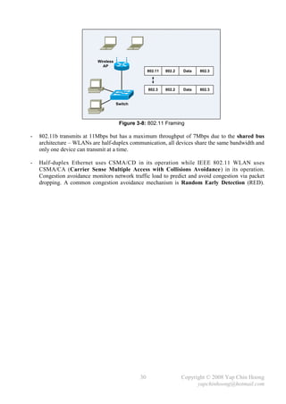
- Route summarization works great in contiguous networks that were designed and planned for it.
RT1 10.1.2.0/30 RT2 10.1.3.0/30 RT3
10.2.1.0 10.3.4.0
10.2.2.0 S0/0 S0/0 10.3.5.0
10.2.3.0 S0/0 S0/1 10.3.6.0
10.2.4.0 10.3.7.0
10.1.1.0/24
Figure 15-3: A Network Designed and Planned for Route Summarization
- Below shows the routing table on RT2 before route summarization, with EIGRP as the routing
protocol. It shows 4 routes to 10.2.x.x subnets out its Serial0/0 interface to RT1, and 4 routes to
10.3.x.x subnets out its Serial0/1 interface to RT3:
RT2#sh ip route
Gateway of last resort is not set
10.0.0.0/8 is variably subnetted, 11 subnets, 2 masks
C 10.1.1.0/24 is directly connected, Ethernet1/0
C 10.1.2.0/30 is directly connected, Serial0/0
C 10.1.3.0/30 is directly connected, Serial0/1
D 10.2.1.0/24 [90/2195456] via 10.1.2.1, 00:02:13, Serial0/0
D 10.2.2.0/24 [90/2195456] via 10.1.2.1, 00:02:13, Serial0/0
D 10.2.3.0/24 [90/2195456] via 10.1.2.1, 00:02:13, Serial0/0
D 10.2.4.0/24 [90/2195456] via 10.1.2.1, 00:02:13, Serial0/0
D 10.3.4.0/24 [90/2195456] via 10.1.3.2, 00:00:18, Serial0/1
D 10.3.5.0/24 [90/2195456] via 10.1.3.2, 00:00:18, Serial0/1
D 10.3.6.0/24 [90/2195456] via 10.1.3.2, 00:00:19, Serial0/1
D 10.3.7.0/24 [90/2195456] via 10.1.3.2, 00:00:19, Serial0/1
RT2#
113 Copyright © 2008 Yap Chin Hoong
yapchinhoong@hotmail.com](https://image.slidesharecdn.com/ccna2ndedition-12877133651663-phpapp02/85/Ccna-2nd-Edition-116-320.jpg)
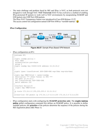
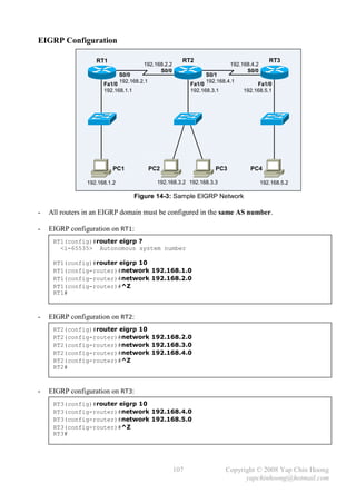
![- RT1 and RT3 are summarizing routers, which advertise summary routes to other routers.
- Route summarization configuration differs with different routing protocols. The ip summary-
address eigrp {as-num} {address} {mask} interface subcommand is used to create a
summary route that is to be advertised out an interface for an EIGRP autonomous system.
Note: EIGRP route summarization takes effect immediately upon the issuance of the
manual summarization command and would tear down EIGRP neighbor relationship;
this ensure neighbors remove previous topology information, and accept to the new topology
information upon the neighborship is recovered.
- Route Summarization configuration on RT1 and RT3:
RT1#conf t
Enter configuration commands, one per line. End with CNTL/Z.
RT1(config)#int s0/0
RT1(config-if)#ip summary-address eigrp 100 10.2.0.0 255.255.0.0
RT1(config-if)#
----------------------------------------------------------------------
RT3#conf t
Enter configuration commands, one per line. End with CNTL/Z.
RT3(config)#int s0/0
RT3(config-if)#ip summary-address eigrp 100 10.3.0.0 255.255.0.0
RT3(config-if)
- Below shows the routing tables on RT1 and RT3 after route summarization:
RT1#sh ip route
Gateway of last resort is not set
10.0.0.0/8 is variably subnetted, 9 subnets, 2 masks
D 10.1.1.0/24 [90/2195456] via 10.1.2.2, 00:04:36, Serial0/0
C 10.1.2.0/30 is directly connected, Serial0/0
D 10.1.3.0/30 [90/2681856] via 10.1.2.2, 00:04:36, Serial0/0
D 10.2.0.0/16 is a summary, 00:04:41, Null0
C 10.2.1.0/24 is directly connected, Ethernet1/0
C 10.2.2.0/24 is directly connected, Ethernet1/1
C 10.2.3.0/24 is directly connected, Ethernet1/2
C 10.2.4.0/24 is directly connected, Ethernet1/3
D 10.3.0.0/16 [90/2707456] via 10.1.2.2, 00:03:05, Serial0/0
RT1#
----------------------------------------------------------------------
RT3#sh ip route
Gateway of last resort is not set
10.0.0.0/8 is variably subnetted, 9 subnets, 2 masks
D 10.1.1.0/24 [90/2195456] via 10.1.3.1, 00:05:32, Serial0/0
D 10.1.2.0/30 [90/2681856] via 10.1.3.1, 00:05:34, Serial0/0
C 10.1.3.0/30 is directly connected, Serial0/0
D 10.2.0.0/16 [90/2707456] via 10.1.3.1, 00:05:32, Serial0/0
D 10.3.0.0/16 is a summary, 00:05:37, Null0
C 10.3.4.0/24 is directly connected, Ethernet1/0
C 10.3.5.0/24 is directly connected, Ethernet1/1
C 10.3.6.0/24 is directly connected, Ethernet1/2
C 10.3.7.0/24 is directly connected, Ethernet1/3
RT3#
114 Copyright © 2008 Yap Chin Hoong
yapchinhoong@hotmail.com](https://image.slidesharecdn.com/ccna2ndedition-12877133651663-phpapp02/85/Ccna-2nd-Edition-117-320.jpg)
![- Static routes can be said to support VLSM, as they can be used to define summary routes for
routing protocols that do not support VLSM, eg: RIP and IGRP.
- Below shows the routing table on RT2 after route summarization:
RT2#sh ip route
Gateway of last resort is not set
10.0.0.0/8 is variably subnetted, 5 subnets, 2 masks
D 10.2.0.0/16 [90/2195456] via 10.1.2.1, 00:03:34, Serial0/0
D 10.3.0.0/16 [90/2195456] via 10.1.3.2, 00:02:06, Serial0/1
C 10.1.1.0/24 is directly connected, Ethernet1/0
C 10.1.2.0/30 is directly connected, Serial0/0
C 10.1.3.0/30 is directly connected, Serial0/1
RT2#
- RT1 no longer seeing the 4 10.3.x.x routes, and RT3 no longer seeing the 4 10.2.x.x routes.
With route summarization, both routers advertise only the summary routes.
Route summarization conserve great amount of bandwidth (smaller routing update packets)
and minimizes processing for routing updates.
- EIGRP route summarization configuration introduces a route destined to the Null0 interface,
where packets matching the route will be discarded. Whenever the summarizing router receives a
packet destined for the summary route but the specific route does not exist in the routing table,
the packet will be matched to the null route and being discarded. This prevents the summarizing
router from forwarding the packet to its default route which would possibly create a routing loop.
The null route will only be seen on the summarizing router.
- To find the best summary route, locate the bits of the subnet numbers that have the common bit
pattern, from left to right (highest-order bits) – this is the subnet mask for the summary route.
- Best summary route for RT1:
00001010 00000010 00000001 00000000 – 10.2.1.0
00001010 00000010 00000010 00000000 – 10.2.2.0
00001010 00000010 00000011 00000000 – 10.2.3.0
00001010 00000010 00000100 00000000 – 10.2.4.0
The best summary route for RT1 is 10.2.0.0, subnet mask 255.255.248.0.
- Best summary route for RT3:
00001010 00000011 00000100 00000000 – 10.3.4.0
00001010 00000011 00000101 00000000 – 10.3.5.0
00001010 00000011 00000110 00000000 – 10.3.6.0
00001010 00000011 00000111 00000000 – 10.3.7.0
The best summary route for RT3 is 10.3.4.0, subnet mask 255.255.252.0.
115 Copyright © 2008 Yap Chin Hoong
yapchinhoong@hotmail.com](https://image.slidesharecdn.com/ccna2ndedition-12877133651663-phpapp02/85/Ccna-2nd-Edition-118-320.jpg)

![- RIPv1 and IGRP perform autosummarization by default, and cannot be disabled – it is a feature
of classful routing protocols. For RIPv2 and EIGRP, the autosummarization feature which
enabled by default can be disabled with the no auto-summary router subcommand.
Autosummarization allows RIPv2 and EIGRP to be backward-compatible with their predecessors
– RIPv1 and IGRP.
- OSPF and IS-IS do no perform autosummarization and do not even have this feature.
RT1 172.16.3.0
RT2
10.3.4.0
S0 10.3.5.0
S1 10.3.6.0
10.3.7.0
10.0.0.0 / 8
172.16.2.0
Figure 16-1: Autosummarization
- Below shows the routing table on RT1 with just a single route to network 10.0.0.0/8 due to the
autosummarization feature of RT2 (RIPv1).
RT1#sh ip route
Gateway of last resort is not set
172.16.0.0/24 is subnetted, 2 subnets
C 172.16.2.0 is directly connected, Ethernet0
C 172.16.3.0 is directly connected, Serial1
R 10.0.0.0/8 [120/1] via 172.16.3.2, 00:00:15, Serial1
RT1#
RT1#debug ip rip
RIP protocol debugging is on
RT1#
00:08:54: RIP: received v1 update from 172.16.3.2 on Serial1
00:08:54: 10.0.0.0 in 1 hops
RT1#
Which route to 10.0.0.0/8 ?!?
RT1 RT2 RT3
10.2.1.0 172.16.1.0 172.16.3.0 10.3.4.0
10.2.2.0 S0 S0 10.3.5.0
10.2.3.0 S0 S1 10.3.6.0
10.2.4.0 10.3.7.0
10.0.0.0 / 8 10.0.0.0 / 8
172.16.2.0
Figure 16-2: The Pitfall of Autosummarization
118 Copyright © 2008 Yap Chin Hoong
yapchinhoong@hotmail.com](https://image.slidesharecdn.com/ccna2ndedition-12877133651663-phpapp02/85/Ccna-2nd-Edition-121-320.jpg)
![- Below shows the routing table of RT2, with RIPv1 as the routing protocol. RT2 has 2 routes to
10.0.0.0/8 network due to autosummarization. RT2 will perform load balancing across the paths
since they are equal-cost paths to the same destination, which will definitely cause
malfunctioning on applications!
RT2#sh ip route
Gateway of last resort is not set
172.16.0.0/24 is subnetted, 3 subnets
C 172.16.1.0 is directly connected, Serial0
C 172.16.2.0 is directly connected, Ethernet0
C 172.16.3.0 is directly connected, Serial1
R 10.0.0.0/8 [120/1] via 172.16.1.1, 00:00:20, Serial0
[120/1] via 172.16.3.2, 00:00:15, Serial1
RT2#
- This problem can be solved by migrating to a classless routing protocol with autosummarization
disabled, eg: RIPv2, EIGRP. Remember to disable autosummarization as it is enabled by default.
- As mentioned before, routing protocols are considered either classful or classless. Nevertheless,
IP routing can also be considered either classful or classless as well.
- The concepts of classful and classless routing are independent of any routing protocol,
as the concepts still applicable to IP routing even if only static routes are being used.
Note: Classlessness can be a characteristic of a routing protocol or a router.
- Classful or classless routing affects how a router uses its default route. A very good topic for the
discussion of classful and classless routing is default routing, where packets destined to
networks with no specific routes in the routing table will be directed to the default route.
- The [no] ip classless global configuration command enables and disables classless routing
respectively. Disabling classless routing is equivalent to enabling classful routing.
- Note: The classless IP behavior is enabled by default in Cisco IOS Release 12.0 and later.
Note: The classless IP behavior has no effect on some later Cisco IOS 12.3 releases.
150.15.100.0/24
RT1 150.15.1.0/24 ISP
.1
.2
10.1.1.0/24
Figure 16-3: Sample Default Routing Network
RT1#conf t
Enter configuration commands, one per line. End with CNTL/Z.
RT1(config)#no ip classless
RT1(config)#ip route 0.0.0.0 0.0.0.0 150.15.1.1
RT1(config)#^Z
RT1#
119 Copyright © 2008 Yap Chin Hoong
yapchinhoong@hotmail.com](https://image.slidesharecdn.com/ccna2ndedition-12877133651663-phpapp02/85/Ccna-2nd-Edition-122-320.jpg)
![RT1#sh ip route
Gateway of last resort is 150.15.1.1 to network 0.0.0.0
150.15.0.0/24 is subnetted, 1 subnets
C 150.15.1.0 is directly connected, Serial0/0
S* 0.0.0.0/0 [1/0] via 150.15.1.1
RT1#
RT1#ping 10.1.1.1
Type escape sequence to abort.
Sending 5, 100-byte ICMP Echos to 10.1.1.1, timeout is 2 seconds:
!!!!!
Success rate is 100 percent (5/5), round-trip min/avg/max = 36/36/40 ms
RT1#ping 150.15.100.1
Type escape sequence to abort.
Sending 5, 100-byte ICMP Echos to 150.15.100.1, timeout is 2 seconds:
.....
Success rate is 0 percent (0/5)
RT1#conf t
Enter configuration commands, one per line. End with CNTL/Z.
RT1(config)#ip classless
RT1(config)#^Z
RT1#ping 150.15.100.1
Type escape sequence to abort.
Sending 5, 100-byte ICMP Echos to 150.15.100.1, timeout is 2 seconds:
!!!!!
Success rate is 100 percent (5/5), round-trip min/avg/max = 36/38/40 ms
RT1#
- As seen from the output above, ping to 150.15.100.1 with classful routing failed, but ping has
succeeded with classless routing. This shows even if there is a default route in the routing table,
it might not be used!
- Cisco IOS uses either classful or classless routing logic when matching a destination IP address
with the routes in the routing table and decide when to use the default route.
- The classful logic – no ip classless:
i) RT1 needs to send a packet to 150.15.100.1.
ii) RT1 matches Class B network – 150.15.0.0, a directly connected network.
Due to it is running classful routing, the default route cannot be used!
iii) RT1 does not have a more specific route to 150.15.100.0 from its routing table.
iv) RT1 discards the packet as the default route cannot be used.
- The classless logic – ip classless:
i) RT1 needs to sends a packet to 150.15.100.1.
ii) RT1 does not have a more specific route to 150.15.100.0.
iii) The default route is being used as there is no specific route matched.
- With classful routing, the default route is only being used when a packet’s destination Class A,
B, or C major network number is not in the routing table.
Ex: A packet destined to 10.2.1.1 is discarded by a classful router with a routing table that
consisting routes to 10.0.0.0/8, 10.1.1.0/24, 10.1.2.0/24, as the major network of 10.2.1.1 –
10.0.0.0/8, is in the routing table.
120 Copyright © 2008 Yap Chin Hoong
yapchinhoong@hotmail.com](https://image.slidesharecdn.com/ccna2ndedition-12877133651663-phpapp02/85/Ccna-2nd-Edition-123-320.jpg)
![- With classless routing, the default route is used whenever a packet does not match a more
specific route in the routing table (unknown subnets of known a classful network).
- If the supernet or default route is learned via a classless routing protocol (eg: OSPF, IS-IS),
the classful nature (the no ip classless global configuration command is configured) of a router
is ignored – a classful router may use a default route to reach networks that are not listed in the
routing table regardless of the ip classless command.
Secondary IP Addressing
- Secondary addressing provides a solution to the problem of running out of addresses in a subnet
(due to poor network design) by allowing multiple networks (or subnets) to reside on the same
data link media. An interface may have an unlimited number of secondary addresses.
RT1
Fa1/0 PC1
10.1.1.1
S0/0
10.1.1.2
10.1.2.0/24 PC2
S0/0
10.1.3.2
Fa1/0
10.1.3.1
RT2 10.1.4.1 secondary
PC3
10.1.4.2
Figure 16-4: Sample Secondary IP Addressing Network
- Secondary IP Addressing configuration on RT2:
RT2(config)#int fa1/0
RT2(config-if)#ip add 10.1.3.1 255.255.255.0
RT2(config-if)#ip add 10.1.4.1 255.255.255.0 secondary
RT2(config-if)#no shut
RT2(config-if)#^Z
RT2#
RT2#sh ip route
Gateway of last resort is not set
10.0.0.0/24 is subnetted, 4 subnets
R 10.1.1.0 [120/1] via 10.1.2.1, 00:00:10, Serial0/0
C 10.1.2.0 is directly connected, Serial0/0
C 10.1.3.0 is directly connected, FastEthernet1/0
C 10.1.4.0 is directly connected, FastEthernet1/0
RT2#
- By implementing secondary IP addressing on RT2, all PCs are able to ping each other.
- Note: RT2 would use its primary IP address (10.1.3.1) as the source IP address when it
communicates with hosts in the secondary network (10.1.4.0/24).
121 Copyright © 2008 Yap Chin Hoong
yapchinhoong@hotmail.com](https://image.slidesharecdn.com/ccna2ndedition-12877133651663-phpapp02/85/Ccna-2nd-Edition-124-320.jpg)
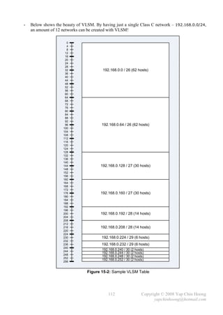
![MTU and Fragmentation
- Maximum Transmission Unit (MTU) defines the maximum amount of network layer data that
a data link layer frame can carry; or the largest packet size that an interface can handle.
This ensures that an IP packet that encapsulates a TCP segment will fit into a single frame.
The default MTU value on Ethernet interfaces is 1500 bytes.
- The following information can be gathered with a packet sniffer, eg: Ethereal, Wireshark:
Max application data size 1460 bytes
Max TCP segments size 1480 bytes
Max IP packets size 1500 bytes
[1]
Max Ethernet frames size 1514 bytes
TCP and IP headers are 20 bytes in length.
[1] 14 bytes = 6 bytes Source MAC address + 6 bytes Destination MAC address + 2 bytes Type.
The actual Ethernet frame size should be 1518 bytes (1514 bytes + 4 bytes FCS).
- Routers are unable to forward a packet out an interface if the packet is larger than the MTU.
Fragmentation is the process of breaking an IP packet into smaller pieces (≤ MTU).
Fragmented packets are reassembled before being passed to the transport layer protocol.
- Fragmentation is performed at network layer (L3) using the 16-bit Identification, 3-bit Flags,
and 13-bit Fragmentation Offset bits in the IP header. The 3-bit Flags field contains the
Don’t fragment bit, More fragments bit, and a reserved bit.
122 Copyright © 2008 Yap Chin Hoong
yapchinhoong@hotmail.com](https://image.slidesharecdn.com/ccna2ndedition-12877133651663-phpapp02/85/Ccna-2nd-Edition-125-320.jpg)
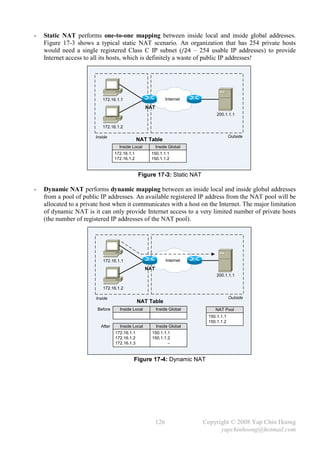
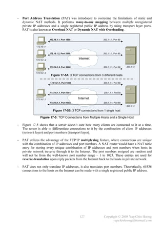
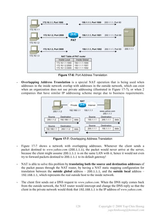
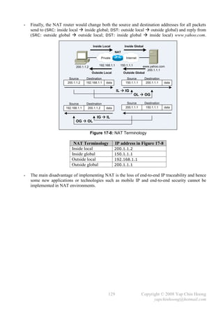

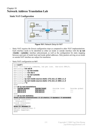
![- Below shows the IP NAT debugging messages when PC1 (172.16.1.2) telnet into ServerA
(200.1.1.200). The debug ip nat privileged command displays every packet that is being
translated by the NAT operation.
NAT#debug ip nat
IP NAT debugging is on
NAT#
00:10:10: NAT: s=172.16.1.2->200.1.1.2, d=200.1.1.200 [0]
00:10:10: NAT: s=200.1.1.200, d=200.1.1.2->172.16.1.2 [0]
00:10:10: NAT*: s=172.16.1.2->200.1.1.2, d=200.1.1.200 [1]
00:10:10: NAT*: s=172.16.1.2->200.1.1.2, d=200.1.1.200 [2]
00:10:10: NAT*: s=172.16.1.2->200.1.1.2, d=200.1.1.200 [3]
00:10:10: NAT*: s=200.1.1.200, d=200.1.1.2->172.16.1.2 [1]
00:10:10: NAT*: s=200.1.1.200, d=200.1.1.2->172.16.1.2 [2]
00:10:10: NAT*: s=200.1.1.200, d=200.1.1.2->172.16.1.2 [3]
NAT#
- Below shows the output of netstat command at ServerA.
C:>netstat -a
Active Connections
Proto Local Address Foreign Address State
TCP ServerA:telnet 200.1.1.2:1050 ESTABLISHED
- The static mappings are created with the ip nat inside source static {inside-local-addr}
{inside-global-addr} global configuration command. The inside keyword tells NAT to translate
the IP addresses in packets sourced from the inside network destined to the outside network.
The source keyword tells NAT to translate the source IP address of the packets.
The static keyword indicates a static entry, which will not be removed from the NAT table
due to timeout or the clear ip nat translation * privileged command.
- The show ip nat translations EXEC command displays the active NAT mappings.
- The show ip nat statistics EXEC command displays the counters for translated packets and
NAT table entries, as well as some basic configuration information.
- The ip nat inside source static {tcp | udp} {inside-local-addr} {local-port-num} {inside-
global-addr | interface {inside-global-intf intf-type intf-num}} {global-port-num} global
configuration command can be used when outside users would like to access an inside resource,
eg: an FTP Server. This command seems to be difficult to understand at the first glance.
However, it would work, as inside source would translate the destination IP addresses in
packets that travel from outside to inside network. This is also known as port forwarding.
- inside source translates the source IP addresses in packets traverse from inside to outside,
and translates the destination IP addresses in packets traverse from outside to inside.
- inside destination translates the destination IP addresses in packets traverse from inside to
outside, and translates the source IP addresses in packets traverse from outside to inside.
- outside source translates the source IP addresses in packets traverse from outside to inside,
and translates the destination IP addresses in packets traverse from inside to outside.
Mostly used when translating overlapping addresses.
132 Copyright © 2008 Yap Chin Hoong
yapchinhoong@hotmail.com](https://image.slidesharecdn.com/ccna2ndedition-12877133651663-phpapp02/85/Ccna-2nd-Edition-135-320.jpg)
![Dynamic NAT Configuration
- An access list is created to include all the hosts on the inside network that are allowed to use
NAT to communicate with outside network. The ip nat pool {pool-name} {start-ip} {end-ip}
{netmask netmask | prefix-length prefix-length} global configuration command defines the
pool of inside global addresses that can be dynamically allocated for dynamic NAT operation.
- Dynamic NAT configuration on NAT:
NAT#conf t
Enter configuration commands, one per line. End with CNTL/Z.
NAT(config)#no ip nat inside source static 172.16.1.2 200.1.1.2
NAT(config)#no ip nat inside source static 172.16.1.3 200.1.1.3
NAT(config)#
NAT(config)#access-list 1 permit 172.16.1.2
NAT(config)#access-list 1 permit 172.16.1.3
NAT(config)#ip nat pool pool01 200.1.1.1 200.1.1.2 netmask 255.255.255.252
NAT(config)#ip nat inside source list 1 pool pool01
NAT(config)#^Z
NAT#
NAT#sh ip nat translations
NAT#sh ip nat statistics
Total active translations: 0 (0 static, 0 dynamic; 0 extended)
Outside interfaces:
Ethernet0/1
Inside interfaces:
Ethernet0/0
Hits: 250 Misses: 0
Expired translations: 0
Dynamic mappings:
-- Inside Source
access-list 1 pool pool01 refcount 0
pool pool01: netmask 255.255.255.252
start 200.1.1.1 end 200.1.1.2
type generic, total addresses 2, allocated 0 (0%), misses 0
NAT# [PC1 Telnet into ServerA]
00:15:33: NAT: s=172.16.1.2->200.1.1.1, d=200.1.1.200 [0]
00:15:33: NAT: s=200.1.1.200, d=200.1.1.1->172.16.1.2 [0]
00:15:33: NAT*: s=172.16.1.2->200.1.1.1, d=200.1.1.200 [1]
00:15:33: NAT*: s=172.16.1.2->200.1.1.1, d=200.1.1.200 [2]
NAT#
NAT#sh ip nat translations
Pro Inside global Inside local Outside local Outside global
--- 200.1.1.1 172.16.1.2 --- ---
NAT#sh ip nat statistics
Total active translations: 1 (0 static, 1 dynamic; 0 extended)
Outside interfaces:
Ethernet0/1
Inside interfaces:
Ethernet0/0
Hits: 260 Misses: 1
Expired translations: 0
Dynamic mappings:
-- Inside Source
access-list 1 pool pool01 refcount 1
pool pool01: netmask 255.255.255.252
start 200.1.1.1 end 200.1.1.2
type generic, total addresses 2, allocated 1 (50%), misses 0
NAT#
133 Copyright © 2008 Yap Chin Hoong
yapchinhoong@hotmail.com](https://image.slidesharecdn.com/ccna2ndedition-12877133651663-phpapp02/85/Ccna-2nd-Edition-136-320.jpg)
![- The access list indicates whether a NAT router should translate the source IP address in a packet.
Only packets with the source or destination addresses that are permitted (matched) in the access
list will be translated. Packets with the source or destination addresses that are not matched by
the access list will not be translated and the will be forwarded normally.
- With the ip nat inside source list 1 pool pool01 command configured, packets that traverse
from inside to outside with a source IP address matched by ACL 1 (172.16.1.2, 172.16.1.3)
will be translated to the an inside global address in the NAT pool pool01 (200.1.1.1, 200.1.1.2).
- The entries in the NAT table will be removed after a period of inactivity (timeout). The clear ip
nat translation * privileged command can be used to forcefully remove all dynamic NAT
entries in the NAT table. The NAT table is stored in memory and is cleared upon router reboot.
Note: Static NAT entries can only be removed with the no form of the static NAT commands in
the global configuration mode.
PAT Configuration
- PAT configuration on NAT:
NAT#conf t
Enter configuration commands, one per line. End with CNTL/Z.
NAT(config)#no ip nat pool pool01
%Pool pool01 in use, cannot destroy
NAT(config)#^Z
NAT#
NAT#clear ip nat translation *
NAT#conf t
NAT(config)#no ip nat pool pool01
NAT(config)#no ip nat inside source list 1 pool pool01
NAT(config)#
NAT(config)#ip nat inside source list 1 interface Ethernet0/1 overload
NAT(config)#^Z
NAT#
NAT# [PC1 and PC2 Telnet into ServerA]
NAT#
NAT#sh ip nat translations
Pro Inside global Inside local Outside local Outside global
tcp 200.1.1.254:1055 172.16.1.2:1055 200.1.1.200:23 200.1.1.200:23
tcp 200.1.1.254:1060 172.16.1.3:1060 200.1.1.200:23 200.1.1.200:23
NAT#
NAT#sh ip nat statistics
Total active translations: 2 (0 static, 2 dynamic; 2 extended)
Outside interfaces:
Ethernet0/1
Inside interfaces:
Ethernet0/0
Hits: 285 Misses: 3
Expired translations: 0
Dynamic mappings:
-- Inside Source
access-list 1 interface Ethernet0/1 refcount 2
Alternative configuration:
NAT(config)#ip nat pool pool02 200.1.1.254 200.1.1.254 netmask 255.255.255.252
NAT(config)#ip nat inside source list 1 pool pool02 overload
134 Copyright © 2008 Yap Chin Hoong
yapchinhoong@hotmail.com](https://image.slidesharecdn.com/ccna2ndedition-12877133651663-phpapp02/85/Ccna-2nd-Edition-137-320.jpg)
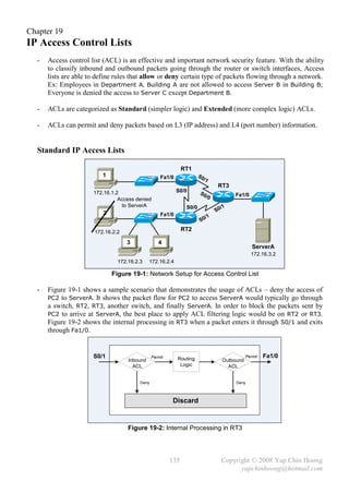
![- Access Control List (ACL) is the term used by Cisco for packet filtering.
- Below are some key features and terminology of Cisco IOS access lists:
i) Filter can be applied when packets entering an interface (before the routing decision).
ii) Filter can be applied when packets leaving an interface (after the routing decision).
iii) Permit Do not filter a packet (forward).
iv) Deny Filter out a packet (discard).
- ACLs are being processed in sequential order. There is always an implicit deny any statement
at the end of every access list. Packets which do not match any permit statement through out an
access list will be filtered due to the implicit deny any rule. The implicit deny any rule can be
overridden with an explicit permit any rule as the last entry in the ACL. An access list should
always have at least one permit statement.
- There are 2 major operations upon an access list: matching and action.
Matching Examines every packet and determines whether it matches a particular ACL
statement.
Action Performs an action (forward or discard) upon the packet when it matches a
particular ACL statement.
- IP, TCP, UDP packets headers are examined in order to retrieve the IP addresses and port
numbers information used in the matching operation.
- What Cisco IOS ACLs examine?
Standard ACLs Only source IP address. Decisions are made based on source IP addresses.
Do not differentiate the types of traffic, eg: WWW, Telnet.
Extended ACLs Source and destination IP addresses, source and destination port numbers,
and specific TCP/IP protocols, eg: ICMP, GRE, etc.
- Below describes the steps of how Cisco IOS processes a packet that enters or exits an interface
with an inbound or outbound access list applied respectively:
i) The matching parameters of the first access-list statement are compared with the packet.
ii) If there is a match, the action defined in the particular access-list statement is
performed (forward or discard). Processing ended for this packet.
iii) If the matching parameters of a particular access-list statement are not matched,
repeat Step 1 and Step 2 with the next statement in the access list until there is a match
(top-down processing).
iv) If there is no match after processing all access list entries, drop the packet
(due to the implicit deny any statement).
- Below lists the syntax of a standard access list statement:
access-list {access-list-number} {deny | permit} {source-addr} [source-wildcard]
- The matching of access-list can be either an entire IP address or just part of an IP address.
Refer back to Figure 19-1, ACLs can be defined to only deny the access of PC2
(match any packet with the source IP address of 172.16.2.2) or all PCs in PC2 subnet
(match any packet with a source IP address that begins with 172.16.2.x).
- Wildcard masks are used in access lists to match a single host, a subnet, or a range of networks
by specifying the portion of an IP address that should be examined by the ACL process.
Its usage is identically in both standard and extended IP access lists.
136 Copyright © 2008 Yap Chin Hoong
yapchinhoong@hotmail.com](https://image.slidesharecdn.com/ccna2ndedition-12877133651663-phpapp02/85/Ccna-2nd-Edition-139-320.jpg)
![- Do not confuse wildcard masks with subnet masks!
0s indicate bits in the address that must be exactly matched.
1s indicate bits in the address that do not need to be matched. Also known as “don’t care” bits.
- Below lists 2 wildcard mask examples:
0.0.0.0 00000000.00000000.00000000.00000000. The entire IP address must be matched.
.
0.0.0.255 00000000.00000000.00000000.11111111. Just the first 24 bits must be matched.
- A wildcard mask can be calculated by subtracting the subnet mask from 255.255.255.255:
i) To match all hosts in a network with subnet mask of 255.255.240.0, the wildcard mask
is 255.255.255.255 – 255.255.240.0 = 0.0.15.255.
ii) To match all hosts in a network with subnet mask of 255.255.128.0, the wildcard mask
is 255.255.255.255 – 255.255.128.0 = 0.0.127.255.
Extended IP Access Lists
- Extended ACLs provide complex and powerful matching logic with the ability to examine many
parts of a packet. A match of an extended access list entry requires that all defined matching
parameters are matched. Action will be taken after the matching process.
- Below lists the syntax of an extended access list statement:
access-list {access-list-number} {deny | permit} {protocol} [host] {source-addr}
[source-wildcard] [src-port] [host] {destination-addr} [destination-wildcard] [dst-port]
- Extended ACL examples:
access-list Statement What It Matches
access-list 101 deny ip any host 172.16.1.1 Any IP packet, any source
IP address, with a
destination of 172.16.1.1.
access-list 101 deny tcp any gt 1023 host 172.16.1.1 eq 23 TCP segments with any
source address, source port
greater than 1023, with a
destination of 172.16.1.1
and destination port of 23.
access-list 101 deny tcp any host 172.16.1.1 eq 23 Same as previous example,
but any source port can be
matched as the source port
parameter is removed.
access-list 101 deny udp 172.16.2.0 0.0.0.255 lt 1023 any UDP segments with a source
address in network
172.16.2.0, source port less
than 1023, with any
destination IP address.
- Below lists the Cisco IOS ACL operators used for matching TCP and UDP port numbers:
lt Less than
gt Greater than
eq Equal to
neq Not equal to
range Range of port numbers
137 Copyright © 2008 Yap Chin Hoong
yapchinhoong@hotmail.com](https://image.slidesharecdn.com/ccna2ndedition-12877133651663-phpapp02/85/Ccna-2nd-Edition-140-320.jpg)
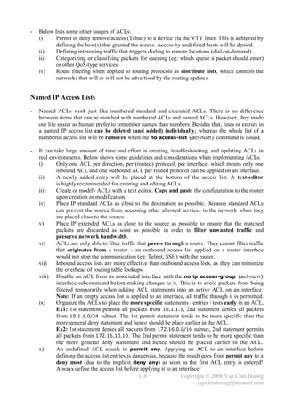
![Chapter 20
IP Access Control Lists Lab
- Remember that access lists use excessive router processing resources. Hence always implement
access lists as short as possible, as effective as possible, and as efficient as possible.
Standard IP Access Lists Configuration
RT1
1 Fa1/0 S0
/1
RT3
172.16.1.2 S0/0 S0
/0 Fa1/0
Access denied
to ServerA S0/0 /1
2 S0
Fa1/0
/1
S0
172.16.2.2 RT2
3 4
ServerA
172.16.3.2
172.16.2.3 172.16.2.4
Figure 20-1: Network Setup for Access Control List
- Standard IP ACLs filter packets by examining only the source IP address in a packet. Standard
ACLs are created with the access-list number 1-99 or 1300-1999 (expanded range), inclusively.
There is no difference between a number to another.
- IP ACLs configuration commands:
Command Description
access-list {access-list-num} {deny | permit} Global configuration command used to
[host] {source-addr} [source-wildcard] add an entry into a standard access list.
access-list {access-list-num} remark {text} Global configuration command used to
add a comment for an access list.
ip access-group {access-list-num} {in | out} Interface subcommand used to apply an
access list on an interface.
access-class {access-list-num} {in | out} Line subcommand used to apply an
access list on VTY remote access lines.
no access-list {access-list-num} Global configuration command used to
remove an access list entirely.
- TO-DO: Implement standard ACLs to deny the access of PC2 to ServerA.
- Standard ACLs should be placed as near to the destination as possible, as standard ACLs often
discard packets that are allowed to forward (or pass) when they are placed close to the source.
Ex: If an inbound ACL is placed on RT2’s Fa1/0, PC2 will never go further than RT2!
Hence the best place to deploy the ACL is on RT3’s Fa1/0 with an outbound standard ACL.
- Another reason is security loopholes might exist when a link between routers fails – packets that
pass through another new path might no longer be passing through the ACL-secured interface.
139 Copyright © 2008 Yap Chin Hoong
yapchinhoong@hotmail.com](https://image.slidesharecdn.com/ccna2ndedition-12877133651663-phpapp02/85/Ccna-2nd-Edition-142-320.jpg)
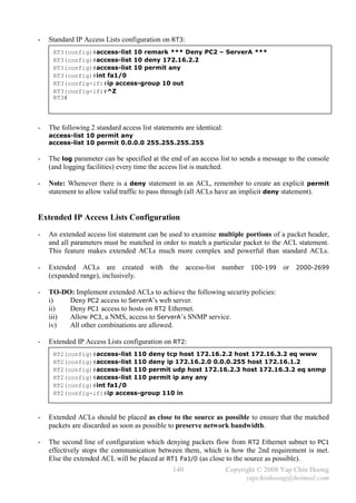
![- The show ip interface [intf-type intf-num] EXEC command displays the placement and
direction of the ACLs applied on a router or a particular interface.
RT2#sh ip interface fa1/0
FastEthernet1/0 is up, line protocol is up
Internet address is 172.16.2.1/24
Broadcast address is 255.255.255.255
Address determined by setup command
MTU is 1500 bytes
Helper address is not set
Directed broadcast forwarding is disabled
Outgoing access list is not set
Inbound access list is 110
Proxy ARP is enabled
Local Proxy ARP is disabled
Security level is default
Split horizon is enabled
ICMP redirects are always sent
ICMP unreachables are always sent
ICMP mask replies are never sent
IP fast switching is enabled
IP fast switching on the same interface is disabled
IP Flow switching is disabled
IP CEF switching is disabled
IP Feature Fast switching turbo vector
IP multicast fast switching is enabled
IP multicast distributed fast switching is disabled
--- output omitted ---
- The show access-lists [acl-num] EXEC command displays all ACLs with their configured
parameters. However, it does not show the association between access lists and interfaces.
Named IP Access Lists Configuration
- Benefits of using named ACLs instead of numbered ACLs:
i) Human have better chance to remember names than numbers.
ii) Deleting individual lines in an access list is possible with the no {acl} negate statement.
- Named ACLs use a global configuration command to enter into ACL configuration mode,
which is the mode for configuring named ACLs statements.
- Named IP Access Lists configuration on RT2:
RT2#conf t
Enter configuration commands, one per line. End with CNTL/Z.
RT2(config)#ip access-list extended example01
RT2(config-ext-nacl)#deny tcp host 172.16.2.2 host 172.16.3.2 eq www
RT2(config-ext-nacl)#deny ip 172.16.2.0 0.0.0.255 host 172.16.3.2
RT2(config-ext-nacl)#permit udp host 172.16.2.3 host 172.16.3.2 eq snmp
RT2(config-ext-nacl)#permit ip any any
RT2(config-ext-nacl)#int fa1/0
RT2(config-if)#ip access-group example01 in
RT2(config-if)#^Z
RT2#
141 Copyright © 2008 Yap Chin Hoong
yapchinhoong@hotmail.com](https://image.slidesharecdn.com/ccna2ndedition-12877133651663-phpapp02/85/Ccna-2nd-Edition-144-320.jpg)
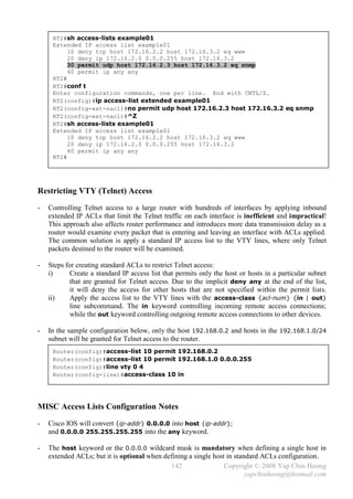
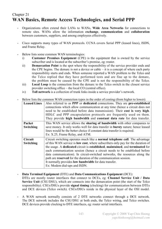
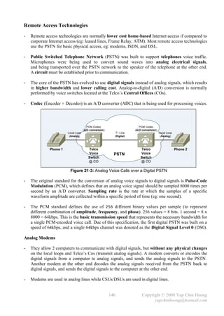
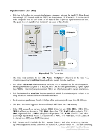
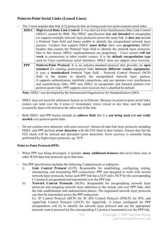
![- Comparisons between synchronous and asynchronous links:
Synchronous Links Asynchronous Links
Have identical frequencies. Each individual Send digital signals without timing. They
character is encapsulated in control bits – the agree on the same speed, but there is no
Start / Stop bits, which designate the beginning checking or adjustment of the rates if they are
and ending of each character. slightly different.
Send frame continuously. Send idle frames No bits are sent during idle times. Only 1 byte
called Receiver Ready when there is no data is sent per transfer.
transmission over the link. The purpose is to
maintain the clock synchronization.
Allow more throughputs (due to clock Require less expensive hardware (do not
synchronization). require clock synchronization).
Normally used for links between routers. Normally used for dial-up links (modems).
Isochronous transmission allows asynchronous data transfer over a synchronous link. It
requires constant bit rate for reliable transport.
- Below list some other common WAN data link protocols:
Error Protocol
Protocol Other Attributes
Recovery? Type Field?
Synchronous Data Link Yes No Developed by IBM. Supports
Control (SDLC) multipoint links. It assumes an
IBM SNA header after the SDLC
header. Replaced by HDLC.
[1]
High-level Data Link No No Developed by IBM. Default on
Control (HDLC) Cisco synchronous serial links.
Qualified Logical Link Developed by IBM to transport
Control (QLLC) SNA traffic over X.25 networks.
[1]
Link Access Procedure, Yes No Mainly used in X.25 networks.
Balanced (LAPB) LAPB operates similar to HDLC,
but is restricted to be used only in
point-to-point links.
Link Access Procedure No No Mainly used on ISDN D channels
– D Channel (LAPD) for signaling in establishing and
terminating ISDN circuits.
Evolved from LAPB.
Link Access Procedure No Yes Mainly used over Frame Relay
for Frame-Mode Bearer links (between a DCE and a DTE).
Services (LAPF) Similar to LAPD.
Point-to-Point Protocol Yes but disabled Yes Designed for multiprotocol
(PPP) by default interoperability.
[1] Cisco’s implementation of LAPB and HDLC includes a proprietary Protocol Type field.
- PPP and ATM can operate on synchronous and asynchronous links; while HDLC and
Frame Relay can only operate on synchronous links.
- PPP, HDLC, and LAPB are the data link layer protocols (or encapsulations) that can be used on
ISDN B channels. PPP uses HDLC to encapsulate and transmit packets over point-to-point links.
152 Copyright © 2008 Yap Chin Hoong
yapchinhoong@hotmail.com](https://image.slidesharecdn.com/ccna2ndedition-12877133651663-phpapp02/85/Ccna-2nd-Edition-155-320.jpg)
![- PPP Encapsulation configuration on RT2:
RT2#conf t
Enter configuration commands, one per line. End with CNTL/Z.
RT2(config)#int s0/0
RT2(config-if)#encapsulation ppp
RT2(config-if)#ip add 10.10.10.2 255.255.255.252
RT2(config-if)#no shut
RT2(config-if)#^Z
RT2#
00:10:10: %LINK-3-UPDOWN: Interface Serial0/0, changed state to up
00:10:13: %LINEPROTO-5-UPDOWN: Line protocol on Interface Serial0/0, changed
state to up
RT2#ping 10.10.10.1
Type escape sequence to abort.
Sending 5, 100-byte ICMP Echos to 10.10.10.1, timeout is 2 seconds:
!!!!!
Success rate is 100 percent (5/5), round-trip min/avg/max = 36/37/40 ms
RT2#
- Verify the PPP Encapsulation configuration on RT2:
RT2#sh int s0/0
Serial0/0 is up, line protocol is up
Hardware is M4T
Internet address is 10.10.10.2/30
MTU 1500 bytes, BW 1544 Kbit, DLY 20000 usec,
reliability 255/255, txload 1/255, rxload 1/255
Encapsulation PPP, crc 16, loopback not set
Keepalive set (10 sec)
LCP Open
Open: IPCP, CDPCP
--- output omitted ---
- The debug ppp negotiation privileged command displays PPP link establishment and
negotiation information, including LCP and NCP information.
- The debug ppp error privileged command displays the errors related to PPP.
- Serialx is xxxx, line protocol is xxxx
The 1st parameter refers to status of the physical layer (L1). It is up when it receives carrier
detect; while it is down when there is a cable or interface problem (hardware failure).
The 2nd parameter refers to status of the data link layer (L2). It is down when there is a
keepalive, clocking (clock rate), framing (encapsulation type), or authentication (password and
authentication protocol) misconfiguration. Note: Usernames are not case-sensitive.
Note: Both interface ends must be configured with the same keepalive value or setting.
- The clear counters [intf-type intf-num] privileged command clears the statistic counters for
all interfaces or a particular interface.
- The no encapsulation ppp command is equivalent to the encapsulation hdlc command,
as it causes routers to revert back to the default encapsulation type – HDLC.
154 Copyright © 2008 Yap Chin Hoong
yapchinhoong@hotmail.com](https://image.slidesharecdn.com/ccna2ndedition-12877133651663-phpapp02/85/Ccna-2nd-Edition-157-320.jpg)
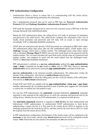
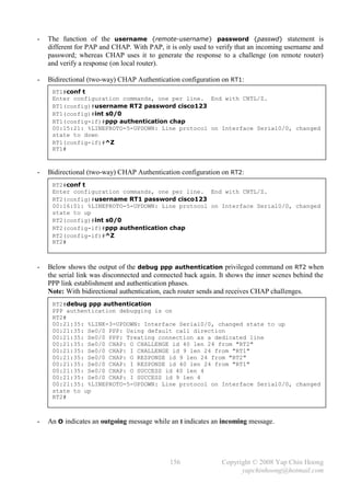
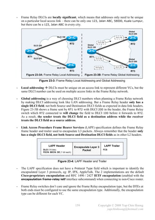
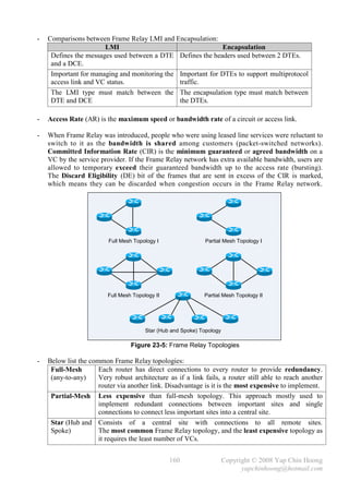
![n (n 1)
- The formula for calculating the number of links in a full-mesh network that has n nodes is .
2
- Below list the options for assigning IP subnets and IP addresses on Frame Relay interfaces:
One IP subnet Mostly used in full-mesh Frame Relay networks. This approach
containing all does not need subinterfaces configuration. Less usage nowadays as
Frame Relay DTEs most organizations implement partial-mesh networks.
One IP subnet per VC Mostly used in partial-mesh Frame Relay networks. Look like a set
of point-to-point serial links. This approach needs point-to-point
subinterfaces configuration. Most commonly implemented.
Hybrid approach Mostly used in networks with a mixture of full-mesh and
partial-mesh Frame Relay networks.
200.1.1.1 200.1.1.2 S0
RT2
200.1.2.1
200.1.1.1 S0 200.1.1.2 200.1.3.1 RT2
S0 S0
200.1.2.2 S0
RT1 S0 200.1.1.3 RT1 RT3
200.1.3.2 S0
RT3 RT4
Subnet 1
Full Mesh
Subnet 2
Subnet 3
Figure 23-6: Frame Relay Layer 3 Addressing
- Subinterface is a Cisco IOS configuration feature that allows a physical interface to be
partitioned into multiple virtual interfaces and have multiple IP addresses on multiple interfaces.
Subinterfaces allow a partial-mesh network to be divided into smaller full-mesh networks.
- Cisco routers support point-to-point and multipoint subinterfaces:
Point-to-Point Used to establish a single PVC to another router. A single VC is considered
in the same group that consists of 2 routers (Subnet 1 and 2 in Figure 23-6).
Each PPP connection has its own subnet and acts like a leased line.
Multipoint Used to establish multiple PVCs to multiple routers. More than 2 routers are
considered in the same group (Subnet 3 in Figure 23-6). All participating
[sub]interfaces are in the same subnet and act like a multi-access network.
- Point-to-point subinterfaces can be used to handle the issues caused by split horizon in partial-
mesh and hub-and-spoke Frame Relay networks implemented with multipoint [sub]interfaces.
- Q: When the term multipoint interface and multiple subinterface are used?
A: Multipoint interface refers to FR multipoint configuration on a main interface, eg: Serial0.
Multipoint subinterface refers to FR multipoint configuration on a subinterface, eg: Serial0.1.
161 Copyright © 2008 Yap Chin Hoong
yapchinhoong@hotmail.com](https://image.slidesharecdn.com/ccna2ndedition-12877133651663-phpapp02/85/Ccna-2nd-Edition-164-320.jpg)
![RT1 RT1
RT2 RT3 RT2 RT3
Figure 23-7A: RT1 with Figure 23-7B: RT1 with
Multipoint (Sub)interface Point-to-Point Subinterfaces
Figure 23-7: Split Horizon in Frame Relay Networks
- Split horizon defines that a routing update received from an interface cannot be readvertised back
to that same interface, hence this prevents RT1 (with a multipoint [sub]interface) from
forwarding the routing updates received from RT2 to RT3 and vice versa. Migration to point-to-
point subinterfaces configuration is recommended to overcome this problem. By having each
subinterface in a separate subnet, routing updates received from a subinterface can be propagated
to other subinterfaces, even though they belong to the same physical interface.
- Another possible solution is disable split horizon on a particular multipoint [sub]interface.
The no ip split-horizon eigrp {as-num} interface subcommand disables split horizon for
EIGRP on a particular multipoint [sub]interface.
Note: Changing the split horizon configuration of an interface would reset EIGRP neighbor
relationships with other routers connected to the interface.
00:04:45: %DUAL-5-NBRCHANGE: IP-EIGRP(0) 100: Neighbor 200.1.1.2 (Serial0/0)
is down: split horizon changed
00:05:40: %DUAL-5-NBRCHANGE: IP-EIGRP(0) 100: Neighbor 200.1.1.2 (Serial0/0)
is up: new adjacency
- Note: EIGRP is categorized as a distance-vector routing protocol hence it inherits the split
horizon feature of DV routing protocols.
- Frame Relay does require Layer 3 broadcast support, eg: routing updates. However, Frame Relay
cannot simply send a single frame to a Frame Relay network and get forwarded to multiple
destinations as like LAN broadcasts; it sends copies of the broadcast to each VC. Broadcast
overhead exists when sending routing updates in networks with large number of routes and VCs.
The issues regarding Frame Relay broadcasts are out of the scope of CCNA.
- ATM are normally being used to build the core of the Frame Relay networks due to the
advantages of ATM. Frame Relay Network and Service Interworking refers to the use of
ATM between 2 Frame Relay switches. Both types use ATM as a transport media.
FRF.5 Defines how a Frame Relay switch can convert a Frame Relay VC to an ATM VC and
back to a Frame Relay VC. The result is transparent to both the end devices (routers).
FRF.8 Defines how 2 end devices (routers) can communicate when a router is connected to a
Frame Relay network and another one is connected to an ATM network.
162 Copyright © 2008 Yap Chin Hoong
yapchinhoong@hotmail.com](https://image.slidesharecdn.com/ccna2ndedition-12877133651663-phpapp02/85/Ccna-2nd-Edition-165-320.jpg)

![Chapter 24
Frame Relay Lab
Full-Mesh Frame Relay Network with One IP Subnet (Multipoint Interfaces)
RT2 DLCI 102
172.16.2.0
S0/0
200.1.1.1
200.1.1.2
S0/0
Full-Mesh
172.16.1.0
Frame Relay
RT1 200.1.1.3
DLCI 101 S0/0
172.16.3.0
RT3 DLCI 103
Figure 24-1: Full-Mesh Frame Relay Network with One IP Subnet
- Frame Relay configuration on RT1, RT2, and RT3:
RTx(config)#int s0/0
RTx(config-if)#encapsulation frame-relay
RTx(config-if)#ip add 200.1.1.{x} 255.255.255.0
RTx(config-if)#no shut
RTx(config-if)#exit
RTx(config)#router eigrp 1
RTx(config-router)#network 200.1.1.0
RTx(config-router)#network 172.16.0.0
RTx(config-router)#no auto-summary
- Note: Watch out for split horizon issues on multipoint [sub]interfaces. Refer to Page 162 for the
discussion and the resolution of this issue.
- Frame Relay configuration can be relatively simple due to the following default IOS settings:
i) The LMI type is automatically sensed. LMI information is exchanged every 10 seconds.
If a router unable to autosense the LMI type, it would use Cisco as the LMI type.
ii) The encapsulation type (of the LAPF headers) is Cisco, instead of IETF.
iii) PVC DLCIs are learned via LMI status messages.
iv) Inverse ARP is enabled by default. It is triggered when a router received the LMI Status
Reply message that declares a VC is active. The router then uses Inverse ARP to discover
and determine the network address of a remote device by advertising itself by sending an
Inverse ARP to each active local DLCI. Inverse ARP messages are sent every 60 seconds.
Note: LMI keepalive messages and LMI status messages are different! LMI keepalive messages
are exchanged between DTE and DCE while LMI status messages are only sent in LMI Status
Reply messages which are sent from DCE to DTE.
- Frame Relay switches do not care about the encapsulation type and IP addressing. They only care
about the LMI type and the CIR.
- A router will be able to figure out the LMI type used in the Frame Relay switch without manual
configuration (with the autosense feature). Manual configuration disables the autosense feature.
165 Copyright © 2008 Yap Chin Hoong
yapchinhoong@hotmail.com](https://image.slidesharecdn.com/ccna2ndedition-12877133651663-phpapp02/85/Ccna-2nd-Edition-168-320.jpg)
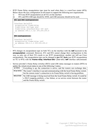
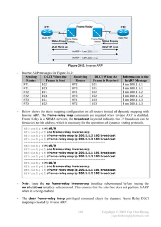
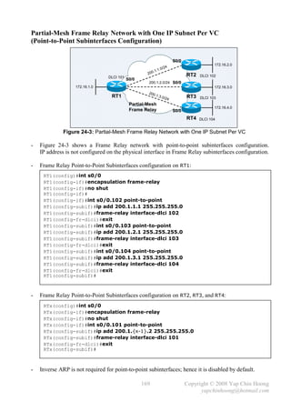
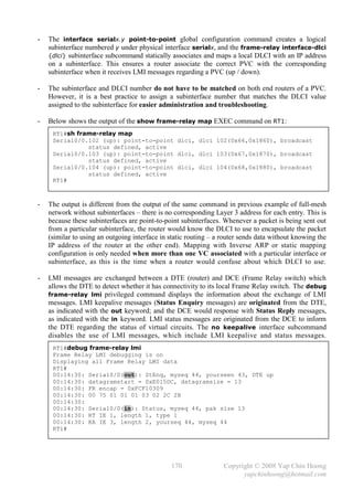
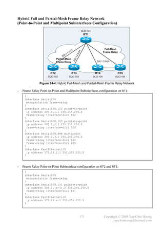
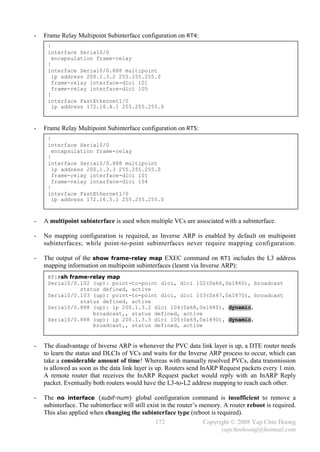
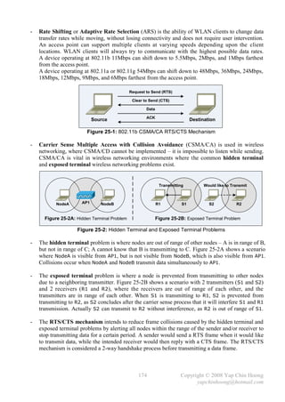
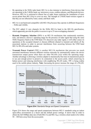
![- Upgrading from 802.11b to 802.11g requires purchasing of new wireless hardware instead of
software upgrade, as 802.11g radios use different chipsets in order to deliver higher data rates.
- 802.11b uses the Direct Sequence Spread Spectrum (DSSS) modulation technique for data
transmission which is not as robust as the Orthogonal Frequency Division Multiplexing
(OFDM) modulation technique used in both 802.11g and 802.11a.
Note: When 802.11g devices are operating at the 802.11b transfer rates, they are actually using
the same modulation technique as 802.11b uses – DSSS. A WLAN with 4 802.11g clients and 1
802.11b client that connected to the same access point are forced to run the 802.11b CSMA/CA
mechanism which really makes throughput suffer. It is recommended to enable the 802.11g-only
mode on an access point in order to optimize performance.
- 802.11n is a new WLAN standard that allows even higher speeds at greater distances. 802.11n is
built upon the 802.11 standards by adding Multiple-Input Multiple-Output (MIMO), which
employs multiple transmitter and receiver antennas to achieve higher data rates and throughput.
802.11n can have up to 8 [smart] antennas, but most of today’s 802.11n access points use 4 – 2
for transmitting simultaneously while another 2 for receiving simultaneously. 802.11n uses wider
channel bandwidth (40MHz) for operation compared to 22MHz as in legacy 802.11 operation.
- The 802.11n standard is not yet been ratified, which means that the “Pre-N” products on the shelf
today are proprietary.
- Bluetooth is another wireless standard for short-range radio connections between laptops,
mobiles phones, digital cameras, headsets, and other portable devices. It can be considered as a
standard for Personal Area Networks (PANs).
- Cisco offers a complete line of indoor and outdoor wireless LAN solutions,
eg: access points, WLAN controllers, WLAN client adapters, security and management servers,
wireless management devices, as well as wireless integrated switches and routers.
- An Infrastructure mode WLAN is either as a Basic Service Set (BSS) with an access point or as
an Extended Service Set (ESS) with multiple access points where multiple BSSs connected by a
common distribution system with all configured with the same SSID for roaming purposes.
Non-root devices (eg: bridges, repeater APs) can only connect to a root device as repeaters.
- Cisco Unified Wireless Network Solution (UWN) allows intelligent Cisco access points and
Cisco WLAN Controllers (WLCs) to be managed through the controller web interface,
the controller itself, or via the Cisco Wireless Control System (WCS). The Cisco WCS works in
conjunction with Cisco Aironet Series Lightweight Access Points, Cisco WLAN Controllers,
and Cisco Wireless Location Appliance to provide a centralized management platform for the
planning, designing, configuring, controlling, managing, and monitoring of enterprise WLANs.
- The Cisco WCS can manage the WLAN controllers and eventually the entire WLAN from a
single GUI interface. It can also provide a detailed insight into the network coverage,
the trending of network statistics, device locations, etc.
- An access point in this type of network requires zero configuration after initial installation,
which means that it can be connected in an indoor or outdoor environment and configured
automatically based on the information provided by WLAN controller. It will even check for
channel overlapping and interference and assign a non-overlapping channel. If it detects an
overlapping channel within its area, it will lower its transmitting level to limit interference –
the automated RF/radio management and automated channel planning features.
177 Copyright © 2008 Yap Chin Hoong
yapchinhoong@hotmail.com](https://image.slidesharecdn.com/ccna2ndedition-12877133651663-phpapp02/85/Ccna-2nd-Edition-180-320.jpg)
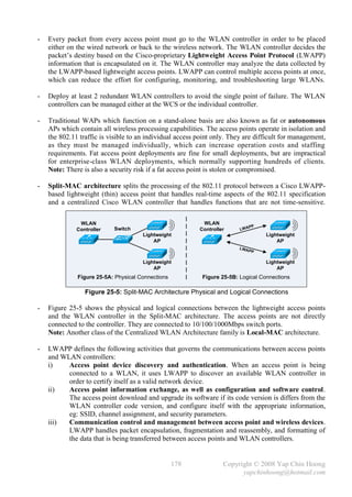
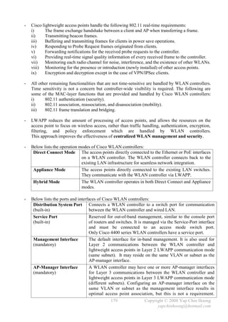
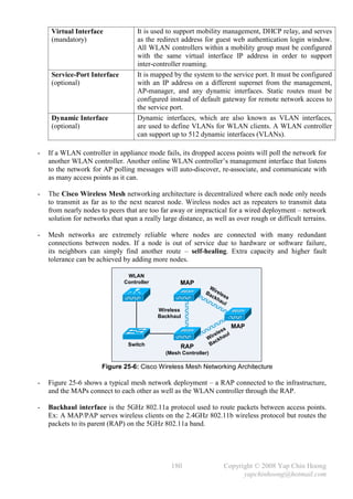
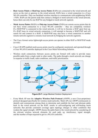
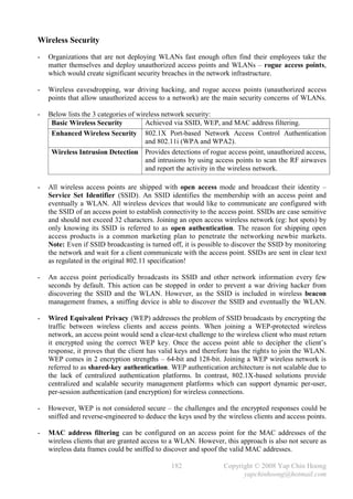
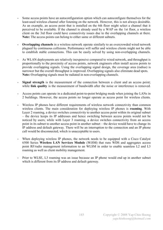
![Cisco Wireless LAN Configuration
- A wireless interface is just another interface on a router. However, enabling the wireless interface
requires more configurations than enabling a FastEthernet interface. Unlike access points,
the interface on the following router is a routed interface, which is the reason why the IP address
is configured under the physical interface. Normally the IP address is configured under the
management VLAN or Bridge Virtual Interface (BVI) on access points.
Router(config)#int dot11radio0/3/0
Router(config-if)#desc *** 1stFloor WLAN ***
Router(config-if)#ip add 10.10.10.1 255.255.255.0
Router(config-if)#no shut
Router(config-if)#ssid 1stFloor-WLAN
Router(config-if-ssid)#guest-mode [1]
Router(config-if-ssid)#authentication open [2]
Router(config-if-ssid)#infrastructure-ssid [3]
Router(config-if-ssid)#no shut
[1] .– .The guest-mode SSID subcommand configures the radio interface to broadcast the SSID.
[2] – Open authentication allows wireless clients to join the open access wireless network
(eg: hot spots) by only knowing its SSID. Additionally, the authentication shared
SSID subcommand configures an access point for shared-key authentication.
[3] – .The infrastructure-ssid SSID subcommand designates a SSID as an infrastructure SSID,
which allows an access point to communicate to other access points, or other devices on
the wired network. Repeater access points and non-root bridges use the specified SSID to
associate with root access points and root bridges respectively (infrastructure associations).
- In Infrastructure mode, all wireless clients communicate with each other through an access
point instead of direct communication; whereas in Ad hoc mode, wireless clients communicate
directly with each other without using an access point.
- Below shows the configuration on a Cisco Aironet access point. Note that the IP address is
configured under the Bridge Virtual Interface (BVI) instead of the Dot11radio interface,
as the interface is not a routed interface as in the previous example. Additionally, the IP address
is used for management only and does not affect the operation of the access point nor the WLAN.
CiscoAP(config)#int dot11Radio0
CiscoAP(config-if)#desc *** 2ndFloor WLAN ***
CiscoAP(config-if)#no shut
CiscoAP(config-if)#ssid 2ndFloor-WLAN
CiscoAP(config-if-ssid)#guest-mode
CiscoAP(config-if-ssid)#authentication open
CiscoAP(config-if-ssid)#infrastructure-ssid
CiscoAP(config-if-ssid)#no shut
CiscoAP(config-if-ssid)#exit
CiscoAP(config)#int bvi1
CiscoAP(config-if)#ip add 11.11.11.1 255.255.255.0
CiscoAP(config-if)#no shut
186 Copyright © 2008 Yap Chin Hoong
yapchinhoong@hotmail.com](https://image.slidesharecdn.com/ccna2ndedition-12877133651663-phpapp02/85/Ccna-2nd-Edition-189-320.jpg)
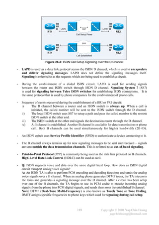
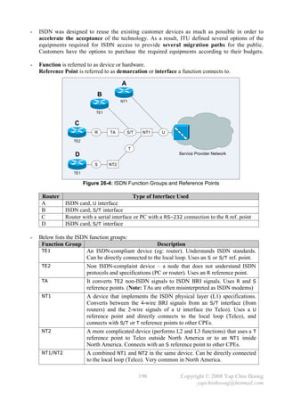
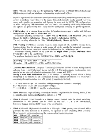
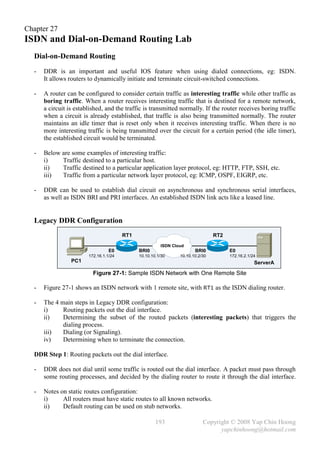
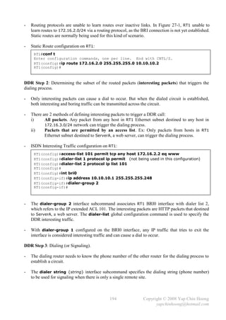
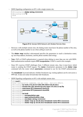
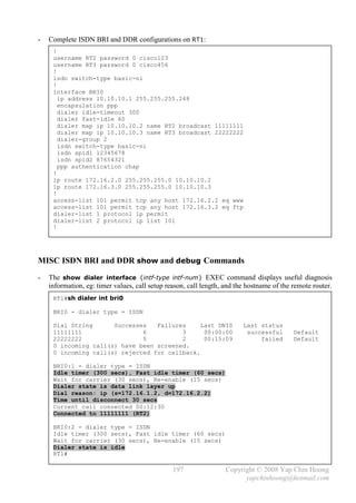
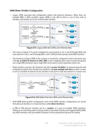
![- DDR Dialer Profiles configuration on RT1:
!
username RT2 password 0 cisco123
username RT3 password 0 cisco456
!
isdn switch-type basic-ni
!
interface BRI0
no ip address
encapsulation ppp
[7] dialer pool-member 1
isdn switch-type basic-ni
isdn spid1 12345678
isdn spid2 87654321
ppp authentication chap
!
interface BRI1
no ip address
encapsulation ppp
[7] dialer pool-member 1
isdn switch-type basic-ni
isdn spid1 23456789
isdn spid2 98765432
ppp authentication chap
!
[3] interface Dialer1
ip address 10.10.10.1 255.255.255.252
encapsulation ppp
[6] dialer pool 1
[4] dialer remote-name RT2
dialer idle-timeout 300
dialer fast-idle 60
dialer string 11111111
dialer-group 1
ppp authentication chap
!
[3] interface Dialer2
ip address 11.11.11.1 255.255.255.252
encapsulation ppp
[6] dialer pool 1
[4] dialer remote-name RT3
dialer idle-timeout 300
dialer fast-idle 60
[5] dialer string 22222222 class dclass-56kpbs
dialer-group 2
ppp authentication chap
!
[1] ip route 172.16.2.0 255.255.255.0 10.10.10.2
ip route 172.16.3.0 255.255.255.0 11.11.11.2
!
[5] map-class dialer dclass-56kpbs
dialer isdn speed 56
!
[2] access-list 101 permit tcp any host 172.16.2.2 eq www
access-list 102 permit tcp any host 172.16.3.2 eq ftp
dialer-list 1 protocol ip list 101
dialer-list 2 protocol ip list 102
!
- Note: IP addresses are configured on dialer interfaces instead of the physical interfaces.
201 Copyright © 2008 Yap Chin Hoong
yapchinhoong@hotmail.com](https://image.slidesharecdn.com/ccna2ndedition-12877133651663-phpapp02/85/Ccna-2nd-Edition-204-320.jpg)
![- With DDR dialer profiles configuration, a dialer interface is created for each remote site.
The dialer string command is used instead of the dialer map command since there is only one
remote site associated with each dialer interface. All dialer interfaces reside in different subnets,
which is like having virtual point-to-point links to each remote site.
- DDR dialer profiles configuration explanations:
1) Each ip route command points to a different next-hop address in different subnet.
2) There are 2 different ACLs as different dialer-list commands were created for each site.
3) The 2 different virtual dialer interfaces contain the commands for dialing to each site.
4) The name of a remote router which was configured as a parameter in the dialer-map
command is replaced with the dialer remote-name {name} interface subcommand.
5) The dialer interface 2 is configured to use a 56kbps B channel with a dialer class.
6) Dialer interfaces are logical and not physical, hence are unable to dial an actual call.
The dialer pool logic associated with a dialer interface will pick an available B channel from
a dialer pool when initiating a call.
7) The 2 BRI interfaces (total 4 B channels) are configured with their corresponding SPIDs, and
are associated to a pool with the dialer pool-member 1 interface subcommand.
Multilink PPP (MLP / MLPPP) Configuration
- It allows the creation of multiple links between routers, which traffic can be load balanced upon.
- Load balancing over parallel links without MLPPP is unpredictable and can be underutilized,
as the Cisco routers default switching mode – fast switching would send all packets destined to
the same IP address over the same link. Whenever some high volume data is being transmitted to
a single IP address, the packets would only be transmitted over a same single link.
- A PC can dial 2 ISDN B channels instead of one for faster connection. MLPPP breaks or
fragments each packet into 2 equal-sized packets, sends each fragment across each link, and
reassembles them back at the other end of the link.
- The dialer load-threshold {load} [inbound | outbound | either] interface subcommand
defines when to bring up the 2nd B channel. The load threshold range is 1 – 255, where 255 tells
the BRI to bring up the 2nd B channel only when the 1st channel is 100% loaded. The second
parameter is inbound, outbound, or either. It calculates the actual load on the interface either on
inbound traffic, outbound traffic, or either direction. The default is outbound.
Note: Multilink PPP is also referred as Bandwidth on Demand (BoD).
- PPP Multilink configuration:
Router(config)#int bri0
Router(config-if)#ppp multilink
Router(config-if)#dialer load-threshold 190 either
- Ex: The dialer load-threshold 190 either interface subcommand tells the BRI interface to
bring up the 2nd B channel if either the inbound or outbound traffic load excesses 75%.
202 Copyright © 2008 Yap Chin Hoong
yapchinhoong@hotmail.com](https://image.slidesharecdn.com/ccna2ndedition-12877133651663-phpapp02/85/Ccna-2nd-Edition-205-320.jpg)
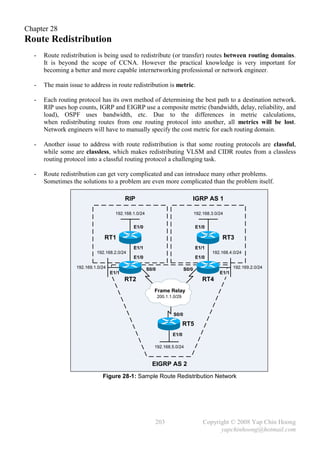
![- Below show the routing tables on all routers before route redistribution:
RT1#sh ip route
Gateway of last resort is not set
C 192.168.1.0/24 is directly connected, Ethernet1/0
C 192.168.2.0/24 is directly connected, Ethernet1/1
--------------------------------------------------
RT2#sh ip route
Gateway of last resort is not set
R 192.168.1.0/24 [120/1] via 192.168.2.1, 00:00:10, Ethernet1/0
C 192.168.2.0/24 is directly connected, Ethernet1/0
D 192.168.5.0/24 [90/1787392] via 200.1.1.3, 00:00:35, Serial0/0
C 192.169.1.0/24 is directly connected, Ethernet1/1
D 192.169.2.0/24 [90/1787392] via 200.1.1.2, 00:00:35, Serial0/0
C 200.1.1.0/29 is directly connected, Serial0/0
--------------------------------------------------
RT3#sh ip route
Gateway of last resort is not set
C 192.168.3.0/24 is directly connected, Ethernet1/0
C 192.168.4.0/24 is directly connected, Ethernet1/1
--------------------------------------------------
RT4#sh ip route
Gateway of last resort is not set
I 192.168.3.0/24 [100/1200] via 192.168.4.1, 00:00:25, Ethernet1/0
C 192.168.4.0/24 is directly connected, Ethernet1/0
D 192.168.5.0/24 [90/1787392] via 200.1.1.3, 00:07:30, Serial0/0
D 192.169.1.0/24 [90/1787392] via 200.1.1.1, 00:07:30, Serial0/0
C 192.169.2.0/24 is directly connected, Ethernet1/1
C 200.1.1.0/29 is directly connected, Serial0/0
--------------------------------------------------
RT5#sh ip route
Gateway of last resort is not set
C 192.168.5.0/24 is directly connected, Ethernet1/0
D 192.169.1.0/24 [90/1787392] via 200.1.1.1, 00:08:15, Serial0/0
D 192.169.2.0/24 [90/1787392] via 200.1.1.2, 00:08:15, Serial0/0
C 200.1.1.0/29 is directly connected, Serial0/0
204 Copyright © 2008 Yap Chin Hoong
yapchinhoong@hotmail.com](https://image.slidesharecdn.com/ccna2ndedition-12877133651663-phpapp02/85/Ccna-2nd-Edition-207-320.jpg)
![Route Redistribution Configuration
- Route redistribution redistributes routes from the source protocol into the destination protocol,
which is achieved by entering the router configuration mode for the destination protocol and
followed by the redistribute router subcommand to bring in the routes of the source protocol.
- The redistribute {protocol} {as-num | process-id} {metric} router subcommand is used to
redistributes routes from one routing protocol to another routing protocol.
- The as-num parameter is applicable only to routing protocols that use AS number identifiers,
eg: IGRP and EIGRP; while the process-id parameter is applicable only to OSPF.
- RT2 is the boundary of for RIP and EIGRP, while RT4 is the boundary of IGRP and EIGRP.
These are the places to redistribute routes between routing domains (or protocols).
- Route Redistribution from EIGRP into RIP configuration on RT2:
RT2(config)#router rip
RT2(config-router)#redistribute eigrp 2 metric 1
RT2(config-router)#
- The configuration above set all routes coming from EIGRP AS 2 as 1 hop count since RIP uses
hop counts as the metric.
- Below shows the routing table on RT1 to verify the EIGRP is properly redistributed into RIP:
RT1#sh ip route
Gateway of last resort is not set
C 192.168.1.0/24 is directly connected, Ethernet1/0
C 192.168.2.0/24 is directly connected, Ethernet1/1
R 192.168.5.0/24 [120/1] via 192.168.2.2, 00:00:15, Ethernet1/1
R 192.169.1.0/24 [120/1] via 192.168.2.2, 00:00:15, Ethernet1/1
R 192.169.2.0/24 [120/1] via 192.168.2.2, 00:00:15, Ethernet1/1
R 200.1.1.0/24 [120/1] via 192.168.2.2, 00:00:15, Ethernet1/1
RT1#
- Route Redistribution from RIP into EIGRP configuration on RT2:
RT2(config)#router eigrp 2
RT2(config-router)#redistribute rip metric ?
<1-4294967295> Bandwidth metric in Kbits per second
RT2(config-router)#redistribute rip metric 2000 ?
<0-4294967295> EIGRP delay metric, in 10 microsecond units
RT2(config-router)#redistribute rip metric 2000 200 ?
<0-255> EIGRP reliability metric where 255 is 100% reliable
RT2(config-router)#redistribute rip metric 2000 200 255 ?
<1-255> EIGRP Effective bandwidth metric (Loading) where 255 is 100% loaded
RT2(config-router)#redistribute rip metric 2000 200 255 1 ?
<1-65535> EIGRP MTU of the path
RT2(config-router)#redistribute rip metric 2000 200 255 1 1500
RT2(config-router)#
205 Copyright © 2008 Yap Chin Hoong
yapchinhoong@hotmail.com](https://image.slidesharecdn.com/ccna2ndedition-12877133651663-phpapp02/85/Ccna-2nd-Edition-208-320.jpg)
![- The configuration above defines 2000 bandwidth metric, 200 microseconds delay, and considers
all links to be 100% reliable and have minimum traffic for all routes redistributed from RIP.
EIGRP route redistribution configuration requires configuring all the composite metric values.
- Note: The subnet mask of the route to the Frame Relay network is /24 instead of /29. This is
because EIGRP has summarized the route to its classful boundary. Additionally, classful routing
protocols (eg: RIP) which do not understand VLSM and CIDR would drop the routing updates.
- Below shows the routing table on RT5 to verify the RIP is properly redistributed into EIGRP:
RT5#sh ip route
Gateway of last resort is not set
D EX 192.168.1.0/24 [170/2221056] via 200.1.1.1, 00:15:30, Serial0/0
D EX 192.168.2.0/24 [170/2221056] via 200.1.1.1, 00:15:30, Serial0/0
C 192.168.5.0/24 is directly connected, Ethernet1/0
D 192.169.1.0/24 [90/2195456] via 200.1.1.1, 00:08:15, Serial0/0
D 192.169.2.0/24 [90/2195456] via 200.1.1.2, 00:08:15, Serial0/0
C 200.1.1.0/29 is directly connected, Serial0/0
RT5#
- Route Redistribution from EIGRP into IGRP configuration on RT4:
RT4(config)#router igrp 1
RT4(config-router)#redistribute eigrp 2 metric 2000 200 255 1 1500
RT4(config-router)#
- Route Redistribution from IGRP into EIGRP configuration on RT4:
RT4(config)#router eigrp 2
RT4(config-router)#redistribute igrp 1 metric 2000 200 255 1 1500
RT4(config-router)#
- Below shows the routing table on RT3 to verify the EIGRP is properly redistributed into IGRP:
RT3#sh ip route
Gateway of last resort is not set
I 192.168.1.0/24 [100/8776] via 192.168.4.2, 00:00:30, Ethernet1/1
I 192.168.2.0/24 [100/8776] via 192.168.4.2, 00:00:30, Ethernet1/1
C 192.168.3.0/24 is directly connected, Ethernet1/0
C 192.168.4.0/24 is directly connected, Ethernet1/1
I 192.168.5.0/24 [100/8676] via 192.168.4.2, 00:00:30, Ethernet1/1
I 192.169.1.0/24 [100/8676] via 192.168.4.2, 00:00:30, Ethernet1/1
I 192.169.2.0/24 [100/1200] via 192.168.4.2, 00:00:30, Ethernet1/1
I 200.1.1.0/24 [100/8576] via 192.168.4.2, 00:00:30, Ethernet1/1
RT3#
- Note: All RIP routes are also shown in RT3 routing table, as the RIP routes have been
redistributed into EIGRP at RT2. So when EIGRP routes are being redistributed into IGRP at
RT4, all the RIP routes are being redistributed into IGRP as well.
206 Copyright © 2008 Yap Chin Hoong
yapchinhoong@hotmail.com](https://image.slidesharecdn.com/ccna2ndedition-12877133651663-phpapp02/85/Ccna-2nd-Edition-209-320.jpg)
![Appendix 1
Cisco IOS Upgrade and Password Recovery Procedures
Cisco Router IOS Upgrade Procedure
Router>
Router>en
Router#conf t
Enter configuration commands, one per line. End with CNTL/Z.
Router(config)#config-register 0x2101
Router(config)#^Z
Router#
Router#sh ver
Cisco Internetwork Operating System Software
IOS (tm) 2500 Software (C2500-IS-L), Version 12.3(12), RELEASE SOFTWARE
(fc3)
Technical Support: http://www.cisco.com/techsupport
Copyright (c) 1986-2004 by cisco Systems, Inc.
Compiled Tue 30-Nov-04 02:33 by kellythw
Image text-base: 0x03094EA4, data-base: 0x00001000
ROM: System Bootstrap, Version 5.2(8a), RELEASE SOFTWARE
BOOTLDR: 3000 Bootstrap Software (IGS-RXBOOT), Version 10.2(8a), RELEASE
SOFTWARE (fc1)
Router uptime is 1 minutes
System returned to ROM by power-on
System image file is "flash:c2500-is-l.123-12.bin"
cisco 2500 (68030) processor (revision N) with 14336K/2048K bytes of memory.
Processor board ID 05534538, with hardware revision 00000000
Bridging software.
X.25 software, Version 3.0.0.
Basic Rate ISDN software, Version 1.1.
1 Ethernet/IEEE 802.3 interface(s)
2 Serial network interface(s)
1 ISDN Basic Rate interface(s)
32K bytes of non-volatile configuration memory.
16384K bytes of processor board System flash (Read ONLY)
Configuration register is 0x2102 (will be 0x2101 at next reload)
Router#reload
System configuration has been modified. Save? [yes/no]: no
Proceed with reload? [confirm]
*Mar 1 00:01:33.871: %SYS-5-RELOAD: Reload requested by console. Reload
Reason: Reload command.
System Bootstrap, Version 5.2(8a), RELEASE SOFTWARE
Copyright (c) 1986-1995 by cisco Systems
2500 processor with 14336 Kbytes of main memory
Restricted Rights Legend
Use, duplication, or disclosure by the Government is
subject to restrictions as set forth in subparagraph
(c) of the Commercial Computer Software - Restricted
Rights clause at FAR sec. 52.227-19 and subparagraph
(c) (1) (ii) of the Rights in Technical Data and Computer
Software clause at DFARS sec. 252.227-7013.
207 Copyright © 2008 Yap Chin Hoong
yapchinhoong@hotmail.com](https://image.slidesharecdn.com/ccna2ndedition-12877133651663-phpapp02/85/Ccna-2nd-Edition-210-320.jpg)
![cisco Systems, Inc.
170 West Tasman Drive
San Jose, California 95134-1706
Cisco Internetwork Operating System Software
IOS (tm) 3000 Bootstrap Software (IGS-RXBOOT), Version 10.2(8a), RELEASE
SOFTWARE (fc1)
Copyright (c) 1986-1995 by cisco Systems, Inc.
Compiled Tue 24-Oct-95 15:46 by mkamson
Image text-base: 0x01020000, data-base: 0x00001000
cisco 2500 (68030) processor (revision N) with 14332K/2048K bytes of memory.
Processor board serial number 05534538 with hardware revision 00000000
X.25 software, Version 2.0, NET2, BFE and GOSIP compliant.
ISDN software, Version 1.0.
1 Ethernet/IEEE 802.3 interface.
2 Serial network interfaces.
1 ISDN Basic Rate interface.
32K bytes of non-volatile configuration memory.
16384K bytes of processor board System flash (Read/Write)
Press RETURN to get started!
Router(boot)>
Router(boot)>en
Router(boot)#conf t
Enter configuration commands, one per line. End with CNTL/Z.
Router(boot)(config)#int e0
Router(boot)(config-if)#ip add 172.16.0.1 255.255.255.0
Router(boot)(config-if)#no shut
Router(boot)(config-if)#^Z
Router(boot)#
Router(boot)#ping 172.16.0.2
Type escape sequence to abort.
Sending 5, 100-byte ICMP Echos to 172.16.0.2, timeout is 2 seconds:
!!!!!
Success rate is 100 percent (5/5), round-trip min/avg/max = 1/203/1004 ms
Router(boot)#copy tftp flash
System flash directory:
File Length Name/status
1 16522128 c2500-is-l.123-12.bin
[16522192 bytes used, 255024 available, 16777216 total]
Address or name of remote host [255.255.255.255]? 172.16.0.2
Source file name? c2500-is-l.123-18.bin
Destination file name [c2500-is-l.123-18.bin]?
Accessing file 'c2500-is-l.123-18.bin' on 172.16.0.2...
Loading c2500-is-l.123-18.bin from 172.16.0.2 (via Ethernet0): ! [OK]
Erase flash device before writing? [confirm]
Flash contains files. Are you sure you want to erase? [confirm]
208 Copyright © 2008 Yap Chin Hoong
yapchinhoong@hotmail.com](https://image.slidesharecdn.com/ccna2ndedition-12877133651663-phpapp02/85/Ccna-2nd-Edition-211-320.jpg)
![Copy 'c2500-is-l.123-18.bin' from server
as 'c2500-is-l.123-18.bin' into Flash WITH erase? [yes/no]yes
Erasing device... eeeeeeeeeeeeeeeeeeee ...erased
Loading c2500-is-l.123-18.bin from 172.16.0.2 (via Ethernet0): !!!!!!!!!!!!!
!!!!!!!!!!!!!!!!!!!!!!!!!!!!!!!!!!!!!!!!!!!!!!!!!!!!!!!!!!!!!!!!!!!!!!!!!!!!
!!!!!!!!!!!!!!!!!!!!!!!!!!!!!!!!!!!!!!!!!!!!!!!!!!!!!!!!!!!!!!!!!!!!!!!!!!!!
!!!!!!!!!!!!!!!!!!!!!!!!!!!!!!!!!!!!!!!!!!!!!!!!!!!!!!!!!!!!!!!!!!!!!!!!!!!!
[OK - 16265152/16777216 bytes]
Verifying checksum... OK (0x40BF)
Flash copy took 0:09:10 [hh:mm:ss]
Router(boot)#
Router(boot)#conf t
Enter configuration commands, one per line. End with CNTL/Z.
Router(boot)(config)#config-register 0x2102
Router(boot)(config)#^Z
Router(boot)#sh ver
Cisco Internetwork Operating System Software
IOS (tm) 3000 Bootstrap Software (IGS-RXBOOT), Version 10.2(8a), RELEASE
SOFTWARE (fc1)
Copyright (c) 1986-1995 by cisco Systems, Inc.
Compiled Tue 24-Oct-95 15:46 by mkamson
Image text-base: 0x01020000, data-base: 0x00001000
ROM: System Bootstrap, Version 5.2(8a), RELEASE SOFTWARE
Router uptime is 11 minutes
System restarted by reload
Running default software
cisco 2500 (68030) processor (revision N) with 14332K/2048K bytes of memory.
Processor board serial number 05534538 with hardware revision 00000000
X.25 software, Version 2.0, NET2, BFE and GOSIP compliant.
ISDN software, Version 1.0.
1 Ethernet/IEEE 802.3 interface.
2 Serial network interfaces.
1 ISDN Basic Rate interface.
32K bytes of non-volatile configuration memory.
16384K bytes of processor board System flash (Read/Write)
Configuration register is 0x2101 (will be 0x2102 at next reload)
Router(boot)#reload
System configuration has been modified. Save? [yes/no]: no
Proceed with reload? [confirm]
- Note: Issue the boot system global configuration command if applicable.
209 Copyright © 2008 Yap Chin Hoong
yapchinhoong@hotmail.com](https://image.slidesharecdn.com/ccna2ndedition-12877133651663-phpapp02/85/Ccna-2nd-Edition-212-320.jpg)
![Catalyst Switch IOS Upgrade Procedure (Cisco IOS Release 12.0)
Switch>
Switch>en
Switch#conf t
Enter configuration commands, one per line. End with CNTL/Z.
Switch(config)#int vlan 1
Switch(config-if)#ip add 172.16.0.1 255.255.255.0
Switch(config-if)#no shut
Switch(config-if)#^Z
Switch#
Switch#ping 172.16.0.2
Type escape sequence to abort.
Sending 5, 100-byte ICMP Echos to 172.16.0.2, timeout is 2 seconds:
!!!!!
Success rate is 100 percent (5/5), round-trip min/avg/max = 1/202/1002 ms
Switch#
Switch#dir
Directory of flash:/
2 -rwx 1809119 Aug 10 2004 23:04:33 c2900xl-c3h2s-mz.120-5.WC10.bin
3 -rwx 105970 Jul 18 2000 01:26:29 c2900XL-diag-mz-120.5.2-XU
4 drwx 704 Aug 10 2004 23:05:26 html
18 -rwx 994 Mar 01 1993 00:00:46 config.text
20 -rwx 329 Mar 01 1993 00:00:50 env_vars
5 -rwx 8192 Aug 10 2004 23:04:34 e2rb.bin
17 -rwx 109 Aug 10 2004 23:05:28 info
3612672 bytes total (571392 bytes free)
Switch#
Switch#del flash:c2900xl-c3h2s-mz.120-5.WC10.bin
Delete filename [c2900xl-c3h2s-mz.120-5.WC10.bin]?
Delete flash:c2900xl-c3h2s-mz.120-5.WC10.bin? [confirm]
Switch#del flash:html/*.*
Delete filename [html/*.*]?
Delete flash:html/homepage.htm? [confirm]
--- output omitted ---
Switch#rmdir flash:html
Rmdir filename [html]?
Delete flash:html? [confirm]
Removed dir flash:html
Switch#dir
Directory of flash:/
3 -rwx 105970 Jul 18 2000 01:26:29 c2900XL-diag-mz-120.5.2-XU
18 -rwx 994 Mar 01 1993 00:00:46 config.text
20 -rwx 329 Mar 01 1993 00:00:50 env_vars
5 -rwx 8192 Aug 10 2004 23:04:34 e2rb.bin
17 -rwx 109 Aug 10 2004 23:05:28 info
3612672 bytes total (3495424 bytes free)
Switch#
210 Copyright © 2008 Yap Chin Hoong
yapchinhoong@hotmail.com](https://image.slidesharecdn.com/ccna2ndedition-12877133651663-phpapp02/85/Ccna-2nd-Edition-213-320.jpg)
![Switch#tar /xtract tftp://172.16.0.2/c2900xl-c3h2s-tar.120-5.WC14.tar flash:
Loading c2900xl-c3h2s-tar.120-5.WC14.tar from 172.16.0.2 (via VLAN1): !!!!!!
extracting c2900xl-c3h2s-mz.120-5.WC14.bin (1811599 bytes)!!!!!!!!!!!!!!!!!!
!!!!!!!!!!!!!!!!!!!!!!!!!!!!!!!!!!!!!!!!!!!!!!!!!!!!!!!!!!!!!!!!!!!!!!!!!!!!
!!!!!!!!!!!!!!!!!!!!!!!!!!!!!!!!!!!!!!!!!!!!!!!!!!!!!!!!!!!!!!!!!!!!!!!!!!!!
extracting e2rb.bin (8192 bytes)!
html/ (directory)
--- output omitted ---
[OK - 2946560 bytes]
Switch#
Switch#dir
Directory of flash:/
2 -rwx 1811599 Mar 01 1993 00:07:37 c2900xl-c3h2s-mz.120-5.WC14.bin
3 -rwx 105970 Jul 18 2000 01:26:29 c2900XL-diag-mz-120.5.2-XU
4 drwx 704 Mar 01 1993 00:08:32 html
18 -rwx 994 Mar 01 1993 00:00:46 config.text
20 -rwx 329 Mar 01 1993 00:00:50 env_vars
5 -rwx 8192 Mar 01 1993 00:07:38 e2rb.bin
17 -rwx 109 Mar 01 1993 00:08:33 info
19 -rwx 109 Mar 01 1993 00:08:33 info.ver
3612672 bytes total (565760 bytes free)
Switch#
Switch#conf t
Enter configuration commands, one per line. End with CNTL/Z.
Switch(config)#boot system flash:c2900xl-c3h2s-mz.120-5.WC14.bin
Switch(config)#^Z
Switch#
Switch#sh boot
BOOT path-list: flash:c2900xl-c3h2s-mz.120-5.WC14.bin
Config file: flash:config.text
Enable Break: no
Manual Boot: no
HELPER path-list:
NVRAM/Config file
buffer size: 32768
Switch#
Switch#reload
System configuration has been modified. Save? [yes/no]: no
Proceed with reload? [confirm]
211 Copyright © 2008 Yap Chin Hoong
yapchinhoong@hotmail.com](https://image.slidesharecdn.com/ccna2ndedition-12877133651663-phpapp02/85/Ccna-2nd-Edition-214-320.jpg)
![Catalyst Switch IOS Upgrade Procedure (Cisco IOS Release 12.1 and later)
Switch>
Switch>en
Switch#conf t
Enter configuration commands, one per line. End with CNTL/Z.
Switch(config)#int vlan 1
Switch(config-if)#ip add 172.16.0.1 255.255.255.0
Switch(config-if)#no shut
Switch(config-if)#^Z
Switch#
Switch#ping 172.16.0.2
Type escape sequence to abort.
Sending 5, 100-byte ICMP Echos to 172.16.0.2, timeout is 2 seconds:
!!!!!
Success rate is 100 percent (5/5), round-trip min/avg/max = 1/200/1000 ms
Switch#
Switch#dir
Directory of flash:/
2 -rwx 2126 Mar 1 1993 00:01:15 +00:00 config.text
4 -rwx 24 Mar 1 1993 00:01:15 +00:00 private-config.text
7 drwx 192 Mar 1 1993 00:13:41 +00:00 c3550-i5k91l2q3-
mz.122-25.SE
8 drwx 192 Mar 1 1993 00:04:27 +00:00 c3550-i9q3l2-mz.121-
19.EA1c
420 -rwx 350 Mar 1 1993 00:13:41 +00:00 system_env_vars
419 -rwx 0 Mar 1 1993 00:13:41 +00:00 env_vars
15998976 bytes total (1409024 bytes free)
Switch#
Switch#delete /force /recursive flash:c3550-i5k91l2q3-mz.122-25.SE
Delete filename [c3550-i5k91l2q3-mz.122-25.SE]?
Switch#
Switch#archive download-sw tftp://172.16.0.2/c3550-ipservicesk9-tar.122-
25.SEE.tar
Loading c3550-ipservicesk9-tar.122-25.SEE.tar from 172.16.0.2 (via Vlan1): !
!!!!!!!!!!!!!!!!!!!!!!!!!!!!!!!!!!!!!!!!!!!!!!!!!!!!!!!!!!!!!!!!!!!!!!!!!!!!
!!!!!!!!!!!!!!!!!!!!!!!!!!!!!!!!!!!!!!!!!!!!!!!!!!!!!!!!!!!!!!!!!!!!!!!!!!!!
!!!!!!!!!!!!!!!!!!!!!!!!!!!!!!!!!!!!!!!!!!!!!!!!!!!!!!!!!!!!!!!!!!!!!!!!!!!!
[OK - 8878080 bytes]
examining image...
extracting info (287 bytes)
Image info:
Version Suffix: ipservicesk9-122-25.SEE
Image Name: c3550-ipservicesk9-mz.122-25.SEE.bin
Version Directory: c3550-ipservicesk9-mz.122-25.SEE
Ios Image Size: 7137792
Total Image Size: 8878592
Image Feature: IP|LAYER_3|PLUS|SSH|3DES|MIN_DRAM_MEG=64
Image Family: C3550
212 Copyright © 2008 Yap Chin Hoong
yapchinhoong@hotmail.com](https://image.slidesharecdn.com/ccna2ndedition-12877133651663-phpapp02/85/Ccna-2nd-Edition-215-320.jpg)
![Extracting files...
extracting info (287 bytes)
extracting c3550-ipservicesk9-mz.122-25.SEE/c3550-ipservicesk9-mz.122-
25.SEE.bin (7131928 bytes)
c3550-ipservicesk9-mz.122-25.SEE/html/ (directory)
extracting c3550-ipservicesk9-mz.122-25.SEE/html/layers.js (1616 bytes)
--- output omitted ---
extracting info.ver (287 bytes)
New software image installed in flash:c3550-ipservicesk9-mz.122-25.SEE
Configuring system to use new image...done.
Switch#
Switch#sh boot
BOOT path-list: flash:c3550-ipservicesk9-mz.122-25.SEE/c3550-
ipservicesk9-mz.122-25.SEE.bin
Config file: flash:/config.text
Private Config file: flash:/private-config.text
Enable Break: no
Manual Boot: no
HELPER path-list:
NVRAM/Config file
buffer size: 393216
Switch#
Switch#reload
System configuration has been modified. Save? [yes/no]: no
Proceed with reload? [confirm]
213 Copyright © 2008 Yap Chin Hoong
yapchinhoong@hotmail.com](https://image.slidesharecdn.com/ccna2ndedition-12877133651663-phpapp02/85/Ccna-2nd-Edition-216-320.jpg)
![Cisco Router Password Recovery Procedure
- Power on the router, and then send a break sequence (Ctrl-Break) to enter ROMmon.
System Bootstrap, Version 5.2(11a), RELEASE SOFTWARE
Copyright (c) 1986-1995 by cisco Systems
4000 processor with 16384 Kbytes of main memory
Abort at 0x10fb602 (PC)
>o
Configuration register = 0xffff2102 at last boot
Bit# Configuration register option settings:
15 Diagnostic mode disabled
14 IP broadcasts do not have network numbers
13 Boot default ROM software if network boot fails
12-11 Console speed is 9600 baud
10 IP broadcasts with ones
08 Break disabled
07 OEM disabled
06 Ignore configuration disabled
03-00 Boot file is cisco2-4000 (or 'boot system' command)
>
[1]
>o/r 0x2142
[2]
>i
System Bootstrap, Version 5.2(11a), RELEASE SOFTWARE
Copyright (c) 1986-1995 by cisco Systems
4000 processor with 16384 Kbytes of main memory
F3: 9248+6029511+165008 at 0x12000
Self decompressing the image :
############################################################################
############################################################################
########################################################## [OK]
Restricted Rights Legend
Use, duplication, or disclosure by the Government is
subject to restrictions as set forth in subparagraph
(c) of the Commercial Computer Software - Restricted
Rights clause at FAR sec. 52.227-19 and subparagraph
(c) (1) (ii) of the Rights in Technical Data and Computer
Software clause at DFARS sec. 252.227-7013.
cisco Systems, Inc.
170 West Tasman Drive
San Jose, California 95134-1706
Cisco Internetwork Operating System Software
IOS (tm) 4000 Software (C4000-JS-M), Version 12.1(27b), RELEASE SOFTWARE
(fc1)
Copyright (c) 1986-2005 by cisco Systems, Inc.
Compiled Tue 16-Aug-05 16:53 by pwade
Image text-base: 0x00012000, data-base: 0x00C19718
[1] – Change the configuration register to ignore the contents of NVRAM.
.Issue the confreg command instead on Cisco 2600 Series and later.
[2] – Issue the reset command instead on Cisco 2600 Series and later.
214 Copyright © 2008 Yap Chin Hoong
yapchinhoong@hotmail.com](https://image.slidesharecdn.com/ccna2ndedition-12877133651663-phpapp02/85/Ccna-2nd-Edition-217-320.jpg)
![cisco 4000 (68030) processor (revision 0xA0) with 16384K/4096K bytes of
memory.
Processor board ID 5079453
G.703/E1 software, Version 1.0.
Bridging software.
X.25 software, Version 3.0.0.
SuperLAT software (copyright 1990 by Meridian Technology Corp).
TN3270 Emulation software.
2 Ethernet/IEEE 802.3 interface(s)
2 Serial network interface(s)
128K bytes of non-volatile configuration memory.
8192K bytes of processor board System flash (Read/Write)
--- System Configuration Dialog ---
Would you like to enter the initial configuration dialog? [yes/no]: no
Press RETURN to get started!
Router>
Router>en
Router#copy startup-config running-config
Router#
Router#conf t
Enter configuration commands, one per line. End with CNTL/Z.
Router(config)#no enable secret
Router(config)#enable secret cisco
Router(config)#
Router(config)#config-register 0x2102
Router(config)#^Z
Router#
Router#sh ver
Cisco Internetwork Operating System Software
IOS (tm) 4000 Software (C4000-JS-M), Version 12.1(27b), RELEASE SOFTWARE
(fc1)
Copyright (c) 1986-2005 by cisco Systems, Inc.
Compiled Tue 16-Aug-05 16:53 by pwade
Image text-base: 0x00012000, data-base: 0x00C19718
--- output omitted ---
Configuration register is 0x2142 (will be 0x2102 at next reload)
Router#
Router#copy running-config startup-config
Building configuration...
[OK]
Router#
215 Copyright © 2008 Yap Chin Hoong
yapchinhoong@hotmail.com](https://image.slidesharecdn.com/ccna2ndedition-12877133651663-phpapp02/85/Ccna-2nd-Edition-218-320.jpg)
![Catalyst Switch Password Recovery Procedure
- Hold down the Mode button located on the left side of the front panel while powering the switch.
Release the Mode button after the Port 1 LED goes out (older models, or the SYST LED stables
(recent models).
C2900XL Boot Loader (C2900-HBOOT-M) Version 12.0(5.2)XU, MAINTENANCE INTERIM
SOFTWARE
Compiled Mon 17-Jul-00 18:19 by ayounes
starting...
Base ethernet MAC Address: 00:04:27:c1:d3:c0
Xmodem file system is available.
The system has been interrupted prior to initializing the
flash filesystem. The following commands will initialize
the flash filesystem, and finish loading the operating
system software:
flash_init
load_helper
boot
switch: flash_init
Initializing Flash...
flashfs[0]: 18 files, 2 directories
flashfs[0]: 0 orphaned files, 0 orphaned directories
flashfs[0]: Total bytes: 3612672
flashfs[0]: Bytes used: 3046912
flashfs[0]: Bytes available: 565760
flashfs[0]: flashfs fsck took 6 seconds.
...done Initializing Flash.
Boot Sector Filesystem (bs:) installed, fsid: 3
Parameter Block Filesystem (pb:) installed, fsid: 4
switch: load_helper
switch: rename flash:config.text flash:config.old
switch: boot
Loading "flash:c2900xl-c3h2s-mz.120-5.WC14.bin"...##########################
############################################################################
############################################################################
File "flash:c2900xl-c3h2s-mz.120-5.WC14.bin" uncompressed and installed,
entry point: 0x3000
executing...
Restricted Rights Legend
Use, duplication, or disclosure by the Government is
subject to restrictions as set forth in subparagraph
(c) of the Commercial Computer Software - Restricted
Rights clause at FAR sec. 52.227-19 and subparagraph
(c) (1) (ii) of the Rights in Technical Data and Computer
Software clause at DFARS sec. 252.227-7013.
cisco Systems, Inc.
170 West Tasman Drive
San Jose, California 95134-1706
216 Copyright © 2008 Yap Chin Hoong
yapchinhoong@hotmail.com](https://image.slidesharecdn.com/ccna2ndedition-12877133651663-phpapp02/85/Ccna-2nd-Edition-219-320.jpg)
![Cisco Internetwork Operating System Software
IOS (tm) C2900XL Software (C2900XL-C3H2S-M), Version 12.0(5)WC14, RELEASE
SOFTWARE (fc1)
Copyright (c) 1986-2006 by cisco Systems, Inc.
Compiled Thu 16-Feb-06 14:39 by antonino
Image text-base: 0x00003000, data-base: 0x00352454
Initializing C2900XL flash...
flashfs[1]: 18 files, 2 directories
flashfs[1]: 0 orphaned files, 0 orphaned directories
flashfs[1]: Total bytes: 3612672
flashfs[1]: Bytes used: 3046912
flashfs[1]: Bytes available: 565760
flashfs[1]: flashfs fsck took 8 seconds.
flashfs[1]: Initialization complete.
...done Initializing C2900XL flash.
C2900XL POST: System Board Test: Passed
--- output omitted ---
cisco WS-C2924-XL (PowerPC403GA) processor (revision 0x11) with 8192K/1024K
bytes of memory.
Processor board ID FAB0444S155, with hardware revision 0x01
Last reset from power-on
Processor is running Enterprise Edition Software
Cluster command switch capable
Cluster member switch capable
24 FastEthernet/IEEE 802.3 interface(s)
32K bytes of flash-simulated non-volatile configuration memory.
Base ethernet MAC Address: 00:04:27:C1:D3:C0
Motherboard assembly number: 73-3382-08
Power supply part number: 34-0834-01
Motherboard serial number: FAB044313HR
Power supply serial number: DAB04232RDQ
Model revision number: A0
Motherboard revision number: C0
Model number: WS-C2924-XL-EN
System serial number: FAB0444S155
C2900XL INIT: Complete
00:00:30: %SYS-5-RESTART: System restarted --
Cisco Internetwork Operating System Software
IOS (tm) C2900XL Software (C2900XL-C3H2S-M), Version 12.0(5)WC14, RELEASE
SOFTWARE (fc1)
Copyright (c) 1986-2006 by cisco Systems, Inc.
Compiled Thu 16-Feb-06 14:39 by antonino
--- System Configuration Dialog ---
At any point you may enter a question mark '?' for help.
Use ctrl-c to abort configuration dialog at any prompt.
Default settings are in square brackets '[]'.
Continue with configuration dialog? [yes/no]: no
Press RETURN to get started.
217 Copyright © 2008 Yap Chin Hoong
yapchinhoong@hotmail.com](https://image.slidesharecdn.com/ccna2ndedition-12877133651663-phpapp02/85/Ccna-2nd-Edition-220-320.jpg)
![Switch>
Switch>en
Switch#rename config.old config.text
Destination filename [config.text]?
Switch#
Switch#copy config.text running-config
Destination filename [running-config]?
994 bytes copied in 2.301 secs (497 bytes/sec)
Switch#
Switch#conf t
Enter configuration commands, one per line. End with CNTL/Z.
Switch(config)#no enable secret
Switch(config)#enable secret cisco
Switch(config)#^Z
Switch#
Switch#copy running-config startup-config
Building configuration...
[OK]
Switch#
218 Copyright © 2008 Yap Chin Hoong
yapchinhoong@hotmail.com](https://image.slidesharecdn.com/ccna2ndedition-12877133651663-phpapp02/85/Ccna-2nd-Edition-221-320.jpg)
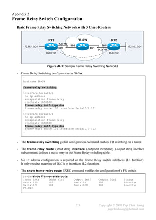
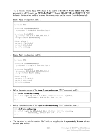
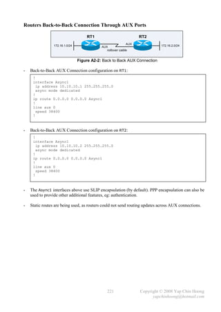
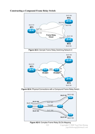
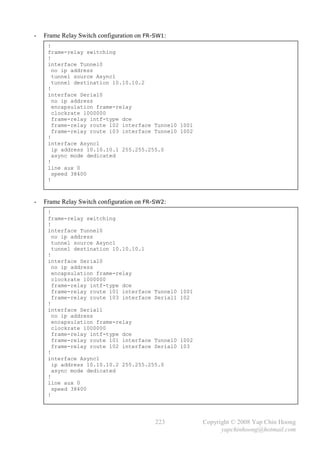


![Appendix 4
Dissecting the Windows Routing Table
C:>ipconfig
Windows IP Configuration
Ethernet adapter Local Area Connection:
Connection-specific DNS Suffix . :
IP Address. . . . . . . . . . . . : 172.16.0.2
Subnet Mask . . . . . . . . . . . : 255.255.255.0
Default Gateway . . . . . . . . . : 172.16.0.1
C:>route print or netstat –r
===========================================================================
Network Destination Netmask Gateway Interface Metric
1 0.0.0.0 0.0.0.0 172.16.0.1 172.16.0.2 1
2 127.0.0.0 255.0.0.0 127.0.0.1 127.0.0.1 1
3 172.16.0.0 255.255.255.0 172.16.0.2 172.16.0.2 20
4 172.16.0.2 255.255.255.255 127.0.0.1 127.0.0.1 20
5 172.16.255.255 255.255.255.255 172.16.0.2 172.16.0.2 20
6 224.0.0.0 240.0.0.0 172.16.0.2 172.16.0.2 20
7 255.255.255.255 255.255.255.255 172.16.0.2 172.16.0.2 1
Default Gateway: 172.16.0.1
===========================================================================
- Gateway is the IP address of the next-hop router inbound interface.
Interface is the IP address of the local router outbound interface.
Metric is the distance to a remote (or destination) network. If there are multiple routes to a same
network, the route with the lowest metric will be used to forward packets to the network.
- Generally, gateway and interface reside in the same subnet.
- Below describes all the routes displayed in the routing table above:
1) Default route or default gateway.
2) Loopback network – destine all packets to the 127.0.0.0/8 network to itself (127.0.0.1).
3) Route to local network – the directly attached network.
4) Route to local host (127.0.0.1), which is identified as a host route.
5) Route to directed broadcast, the broadcast which is sent to all hosts of a particular subnet or
a group of subnets. It is identified as a host route. May be forwarded by a router (normally
the default gateway) configured with the ip directed-broadcast interface subcommand.
6) Route to multicast networks.
7) Route to flooded / limited broadcast, the local broadcast within a subnet. It is identified as a
host route. Normally sent by hosts that do not know their network numbers and addresses and
are querying some servers for those information (eg: DHCP). May be forwarded by routers
with the ip helper-address {ip-addr} interface subcommand.
Note: Host routes are destinations with the subnet mask of 255.255.255.255.
- Below shows the command syntax for adding a [persistent] route:
route [-p] add {dest-net-addr} mask {netmask} {gw-ip-addr} [metric {metric}]
- Below shows the command syntax for deleting or removing an existing [persistent] route:
route delete {dest-net-addr} [mask {netmask} [gw-ip-addr]]
229 Copyright © 2008 Yap Chin Hoong
yapchinhoong@hotmail.com](https://image.slidesharecdn.com/ccna2ndedition-12877133651663-phpapp02/85/Ccna-2nd-Edition-232-320.jpg)


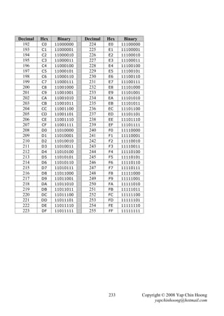

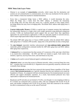
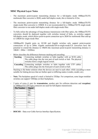
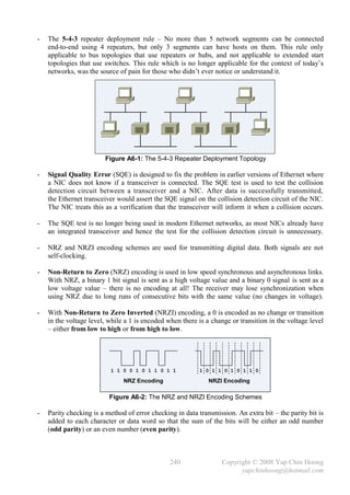
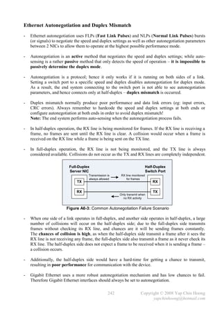
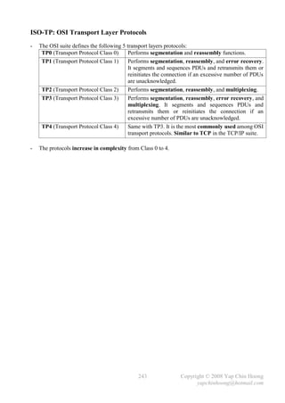
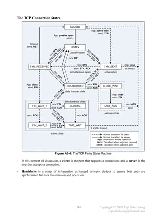
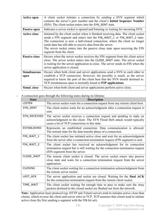
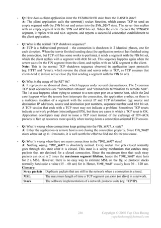
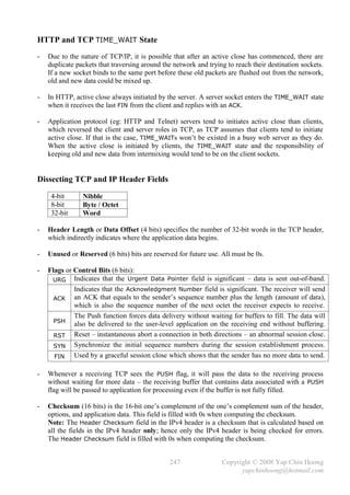
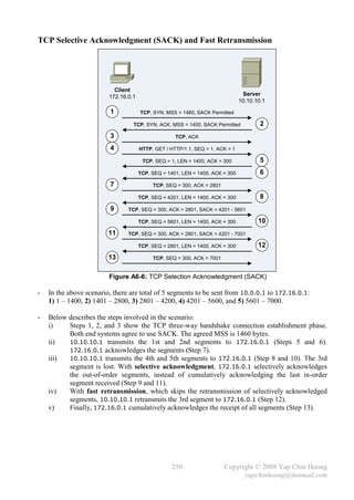
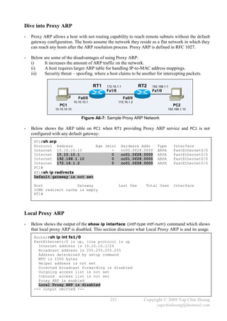
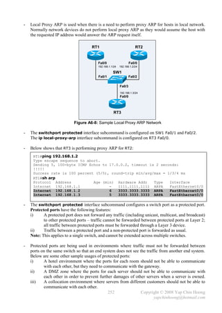
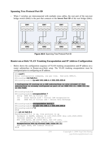
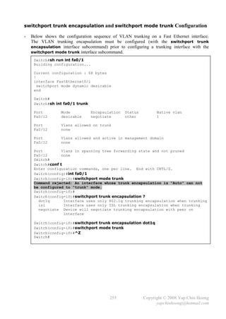
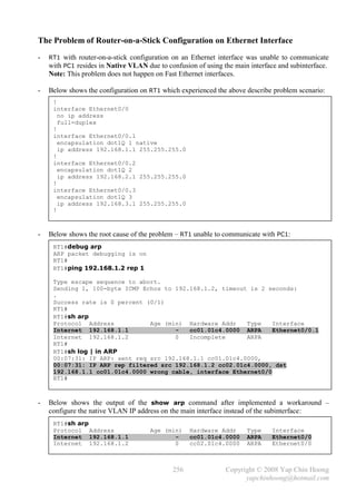
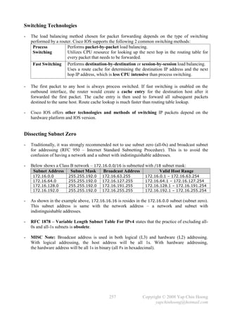
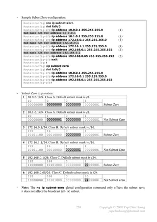
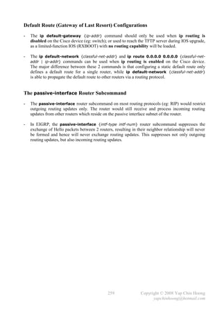
![The permanent keyword in the Static Route Configuration
- Without the permanent keyword in a static route statement, an inactive interface will cause the
directly connected network and all the associated static routes removed from the routing table.
- Adding the permanent keyword to a static route statement will keep the static route remains in
the routing table no matter what happens, even if the interface associated with the static route
goes down (or shutdown) or the directly-connected network is removed from the routing table.
- The advantage of this option is that static routes do not need to be processed for insertion into /
removal from the routing table upon interface status change, hence saving processing resources.
The processing time for static routing insertion into / removal from the routing table is 1 second.
Prior to Cisco IOS Release 12.0, this processing time was 5 seconds.
- Note: Configuring static routes with the permanent keyword could make a subnet that doesn’t
even exist to be shown in the routing table!
- Below shows the behavior of the routing table before and after using the permanent keyword:
Router#sh run | in ip route
ip route 172.16.1.0 255.255.255.0 10.10.10.2
Router#
Router#sh ip route
Gateway of last resort is not set
172.16.0.0/24 is subnetted, 1 subnets
S 172.16.1.0 [1/0] via 10.10.10.2
10.0.0.0/30 is subnetted, 1 subnets
C 10.10.10.0 is directly connected, Serial1/0
Router#
Router#debug ip routing
IP routing debugging is on
Router#
00:03:34: is_up: 1 state: 4 sub state: 1 line: 0
00:03:42: %LINEPROTO-5-UPDOWN: Line protocol on Interface Serial1/0, changed
state to down
00:03:42: is_up: 0 state: 4 sub state: 1 line: 0
00:03:42: RT: interface Serial1/0 removed from routing table
00:03:42: RT: del 10.10.10.0/30 via 0.0.0.0, connected metric [0/0]
00:03:42: RT: delete subnet route to 10.10.10.0/30
00:03:42: RT: delete network route to 10.0.0.0
00:03:43: RT: del 172.16.1.0/24 via 10.10.10.2, static metric [1/0]
00:03:43: RT: delete subnet route to 172.16.1.0/24
00:03:43: RT: delete network route to 172.16.0.0
Router#
Router#sh ip route
Gateway of last resort is not set
Router#
260 Copyright © 2008 Yap Chin Hoong
yapchinhoong@hotmail.com](https://image.slidesharecdn.com/ccna2ndedition-12877133651663-phpapp02/85/Ccna-2nd-Edition-263-320.jpg)
![Router#conf t
Enter configuration commands, one per line. End with CNTL/Z.
Router(config)#no ip route 172.16.1.0 255.255.255.0
Router(config)#ip route 172.16.1.0 255.255.255.0 10.10.10.2 permanent
Router(config)#^Z
Router#
00:05:22: %LINEPROTO-5-UPDOWN: Line protocol on Interface Serial1/0, changed
state to up
00:05:22: is_up: 1 state: 4 sub state: 1 line: 0
00:05:22: RT: add 10.10.10.0/30 via 0.0.0.0, connected metric [0/0]
00:05:22: RT: interface Serial1/0 added to routing table
00:05:23: RT: add 172.16.1.0/24 via 10.10.10.2, static metric [1/0]
Router#
Router#sh ip route
Gateway of last resort is not set
172.16.0.0/24 is subnetted, 1 subnets
S 172.16.1.0 [1/0] via 10.10.10.2
10.0.0.0/30 is subnetted, 1 subnets
C 10.10.10.0 is directly connected, Serial1/0
Router#
Router#
00:06:04: is_up: 1 state: 4 sub state: 1 line: 0
00:06:12: %LINEPROTO-5-UPDOWN: Line protocol on Interface Serial1/0, changed
state to down
00:06:12: is_up: 0 state: 4 sub state: 1 line: 0
00:06:12: RT: interface Serial1/0 removed from routing table
00:06:12: RT: del 10.10.10.0/30 via 0.0.0.0, connected metric [0/0]
00:06:12: RT: delete subnet route to 10.10.10.0/30
00:06:12: RT: delete network route to 10.0.0.0
Router#
Router#sh ip route
Gateway of last resort is not set
172.16.0.0/24 is subnetted, 1 subnets
S 172.16.1.0 [1/0] via 10.10.10.2
Router#
Router#conf t
Enter configuration commands, one per line. End with CNTL/Z.
Router(config)#int s1/0
Router(config-if)#shut
Router(config-if)#^Z
Router#
00:06:35: is_up: 0 state: 6 sub state: 1 line: 0
00:06:37: %LINK-5-CHANGED: Interface Serial1/0, changed state to
administratively down
00:06:37: is_up: 0 state: 6 sub state: 1 line: 0
Router#
Router#sh ip route
Gateway of last resort is not set
172.16.0.0/24 is subnetted, 1 subnets
S 172.16.1.0 [1/0] via 10.10.10.2
Router#
261 Copyright © 2008 Yap Chin Hoong
yapchinhoong@hotmail.com](https://image.slidesharecdn.com/ccna2ndedition-12877133651663-phpapp02/85/Ccna-2nd-Edition-264-320.jpg)
![RIPv1 and VLSM
192.168.0.1/28 192.168.0.33/28 192.168.0.65/28
Fa0/0 Fa0/0 Fa0/0
192.168.0.18/28 192.168.0.50/28
S1/0 S1/0
RT1 S1/1 S1/1 RT3
192.168.0.17/28 192.168.0.49/28
S1/0 RT2 S1/1
192.168.0.81/28 192.168.0.97/28
192.168.0.82/28 192.168.0.98/28
S1/0 192.168.0.130/28
RT5 192.168.0.162/28 S1/1
S1/0 S1/0
RT4 S1/1 S1/1
RT6
192.168.0.129/28 192.168.0.161/28
Fa0/0 Fa0/0 Fa0/0
192.168.0.113/28 192.168.0.145/28 192.168.0.177/28
Figure A6-9: Sample RIPv1 and VLSM Network
- The network above is subnetted using a Class C address block. In the network above, there are a
total of 12 networks (6 LANs and 6 point-to-point WANs). The 255.255.255.240 (/28) subnet
mask is used to support a maximum of 16 networks with 14 usable IP addresses on each LAN.
- RIPv1 does not support VLSM information, so all networks must have the same subnet mask.
- This sample setup shows that even RIP does not support VLSM, such networks can be setup
when all subnets are using the same subnet mask.
- Below shows the routing table on RT1:
RT1#sh ip route
192.168.0.0/28 is subnetted, 12 subnets
C 192.168.0.0 is directly connected, FastEthernet0/0
C 192.168.0.16 is directly connected, Serial1/1
R 192.168.0.32 [120/1] via 192.168.0.18, 00:00:01, Serial1/1
R 192.168.0.48 [120/1] via 192.168.0.18, 00:00:01, Serial1/1
R 192.168.0.64 [120/2] via 192.168.0.18, 00:00:01, Serial1/1
C 192.168.0.80 is directly connected, Serial1/0
R 192.168.0.96 [120/2] via 192.168.0.18, 00:00:01, Serial1/1
R 192.168.0.112 [120/1] via 192.168.0.82, 00:00:12, Serial1/0
R 192.168.0.128 [120/1] via 192.168.0.82, 00:00:12, Serial1/0
R 192.168.0.144 [120/2] via 192.168.0.82, 00:00:13, Serial1/0
R 192.168.0.160 [120/2] via 192.168.0.82, 00:00:12, Serial1/0
R 192.168.0.176 [120/3] via 192.168.0.18, 00:00:01, Serial1/1
[120/3] via 192.168.0.82, 00:00:12, Serial1/0
RT1#
262 Copyright © 2008 Yap Chin Hoong
yapchinhoong@hotmail.com](https://image.slidesharecdn.com/ccna2ndedition-12877133651663-phpapp02/85/Ccna-2nd-Edition-265-320.jpg)
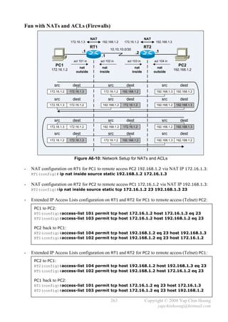
![- Below shows the NAT operations on RT1 and RT2 and ACL hit counts when PC1 accesses PC2:
RT1#debug ip nat
IP NAT debugging is on
RT1#
00:02:30: NAT: s=172.16.1.2, d=172.16.1.3->192.168.1.2 [14748]
00:02:32: NAT: s=172.16.1.2, d=172.16.1.3->192.168.1.2 [14748]
00:02:36: NAT: s=172.16.1.2, d=172.16.1.3->192.168.1.2 [14748]
00:02:38: NAT*: s=192.168.1.2->172.16.1.3, d=172.16.1.2 [19343]
00:02:38: NAT*: s=172.16.1.2, d=172.16.1.3->192.168.1.2 [14749]
00:02:38: NAT*: s=172.16.1.2, d=172.16.1.3->192.168.1.2 [14750]
--- output omitted ---
RT1#
RT1#sh access-list
Extended IP access list 101
10 permit tcp host 172.16.1.2 host 172.16.1.3 eq telnet (28 matches)
20 permit tcp host 172.16.1.2 eq telnet host 172.16.1.3
Extended IP access list 102
10 permit tcp host 192.168.1.2 eq telnet host 172.16.1.2 (14 matches)
20 permit tcp host 192.168.1.2 host 172.16.1.2 eq telnet
RT1#
RT1#sh ip nat statistics
Total active translations: 1 (1 static, 0 dynamic; 0 extended)
Outside interfaces:
FastEthernet0/0
Inside interfaces:
FastEthernet1/0
Hits: 36 Misses: 0
Expired translations: 0
Dynamic mappings:
RT1#
----------------------------------------------------------------------
RT2#
00:02:31: NAT: s=172.16.1.2->192.168.1.3, d=192.168.1.2 [14748]
00:02:37: NAT*: s=192.168.1.2, d=192.168.1.3->172.16.1.2 [19343]
00:02:37: NAT*: s=172.16.1.2->192.168.1.3, d=192.168.1.2 [14749]
--- output omitted ---
RT2#sh access-list
Extended IP access list 103
10 permit tcp host 172.16.1.2 host 192.168.1.2 eq telnet (25 matches)
20 permit tcp host 172.16.1.2 eq telnet host 192.168.1.2
Extended IP access list 104
10 permit tcp host 192.168.1.2 eq telnet host 192.168.1.3 (14 matches)
20 permit tcp host 192.168.1.2 host 192.168.1.3 eq telnet
RT2#
----------------------------------------------------------------------
PC1#telnet 172.16.1.3
Trying 172.16.1.3 ... Open
User Access Verification
Password:
PC2>who
Line User Host(s) Idle Location
0 con 0 idle 00:00:56
* 66 vty 0 idle 00:00:00 192.168.1.3
Interface User Mode Idle Peer Address
PC2>
264 Copyright © 2008 Yap Chin Hoong
yapchinhoong@hotmail.com](https://image.slidesharecdn.com/ccna2ndedition-12877133651663-phpapp02/85/Ccna-2nd-Edition-267-320.jpg)
![- Below shows the NAT operations on RT2 and RT1 and ACL hit counts when PC2 accesses PC1:
RT2#debug ip nat
IP NAT debugging is on
RT2#
00:04:42: NAT: s=192.168.1.2, d=192.168.1.3->172.16.1.2 [50878]
00:04:42: NAT*: s=172.16.1.2->192.168.1.3, d=192.168.1.2 [2634]
00:04:42: NAT*: s=192.168.1.2, d=192.168.1.3->172.16.1.2 [50879]
00:04:42: NAT*: s=192.168.1.2, d=192.168.1.3->172.16.1.2 [50880]
--- output omitted ---
RT2#
RT2#sh access-list
Extended IP access list 103
10 permit tcp host 172.16.1.2 host 192.168.1.2 eq telnet
20 permit tcp host 172.16.1.2 eq telnet host 192.168.1.2 (17 matches)
Extended IP access list 104
10 permit tcp host 192.168.1.2 eq telnet host 192.168.1.3
20 permit tcp host 192.168.1.2 host 192.168.1.3 eq telnet (25 matches)
RT2#
RT2#sh ip nat statistics
Total active translations: 1 (1 static, 0 dynamic; 0 extended)
Outside interfaces:
FastEthernet0/0
Inside interfaces:
FastEthernet1/0
Hits: 40 Misses: 0
Expired translations: 0
Dynamic mappings:
RT2#
----------------------------------------------------------------------
RT1#
00:04:43: NAT: s=192.168.1.2->172.16.1.3, d=172.16.1.2 [50878]
00:04:43: NAT*: s=172.16.1.2, d=172.16.1.3->192.168.1.2 [2634]
00:04:43: NAT*: s=192.168.1.2->172.16.1.3, d=172.16.1.2 [50879]
00:04:43: NAT*: s=172.16.1.2, d=172.16.1.3->192.168.1.2 [2635]
--- output omitted ---
RT1#sh access-list
Extended IP access list 101
10 permit tcp host 172.16.1.2 host 172.16.1.3 eq telnet
20 permit tcp host 172.16.1.2 eq telnet host 172.16.1.3 (17 matches)
Extended IP access list 102
10 permit tcp host 192.168.1.2 eq telnet host 172.16.1.2
20 permit tcp host 192.168.1.2 host 172.16.1.2 eq telnet (25 matches)
RT1#
----------------------------------------------------------------------
PC2#telnet 192.168.1.3
Trying 192.168.1.3 ... Open
User Access Verification
Password:
PC1>
PC1>who
Line User Host(s) Idle Location
0 con 0 idle 00:00:35
* 66 vty 0 idle 00:00:00 172.16.1.3
Interface User Mode Idle Peer Address
PC1>
265 Copyright © 2008 Yap Chin Hoong
yapchinhoong@hotmail.com](https://image.slidesharecdn.com/ccna2ndedition-12877133651663-phpapp02/85/Ccna-2nd-Edition-268-320.jpg)
![Bidirectional (2-Way) NAT
RT1
.1 .1
nat nat
inside outside
PC1 PC2
172.16.1.2 Outbound NAT 192.168.1.2
172.16.1.2 192.168.1.3
Inbound NAT
172.16.1.3 192.168.1.2
RT1#show ip nat translations
Pro Inside global Inside local Outside local Outside global
--- --- --- 172.16.1.3 192.168.1.2
--- 192.168.1.3 172.16.1.2 --- ---
--- 192.168.1.3 172.16.1.2 172.16.1.3 192.168.1.2
RT1#
Figure A6-11: Network Setup for Bidirectional (2-Way) NAT
- Traditional Outbound NAT is designed to handle outbound connections, in which clients of the
inside local network initiate requests to outside global Internet hosts. Bidirectional NAT,
2-Way NAT, or Inbound NAT is an enhancement upon NAT to handle connections initiated
from the outside network.
- The network setup on Figure A6-10 can be achieved using a single router. PC1 accesses PC2
using 172.16.1.3 outside local; while PC2 accesses PC1 using 192.168.1.3 inside global.
- Bidirectional NAT configuration on RT1:
!
interface FastEthernet0/0
ip address 172.16.1.1 255.255.255.0
ip nat inside
!
interface FastEthernet1/0
ip address 192.168.1.1 255.255.255.0
ip nat outside
!
ip nat inside source static 172.16.1.2 192.168.1.3
ip nat outside source static 192.168.1.2 172.16.1.3 add-route
!
- The add-route keyword adds a static /32 host route for the outside local address. This route is
used for routing and translating packets that travel from the inside to the outside of the network.
RT1#sh ip route
Gateway of last resort is not set
172.16.0.0/16 is variably subnetted, 2 subnets, 2 masks
C 172.16.1.0/24 is directly connected, FastEthernet0/0
S 172.16.1.3/32 [1/0] via 192.168.1.2
C 192.168.1.0/24 is directly connected, FastEthernet1/0
RT1#
266 Copyright © 2008 Yap Chin Hoong
yapchinhoong@hotmail.com](https://image.slidesharecdn.com/ccna2ndedition-12877133651663-phpapp02/85/Ccna-2nd-Edition-269-320.jpg)
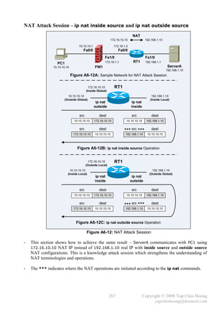
![- Note: A router does not require a physical nor logical interface to reside in the NAT IP address
subnet for the operation of NAT – 172.16.10.0/24 in this case. As compared to the previous
section – NAT with Virtual Interface, which the router has a logical loopback interface and
advertising the NAT IP subnet (10.2.2.0/24) using EIGRP.
- RT1 configuration for ip nat inside source operation:
!
interface FastEthernet0/0
ip address 172.16.1.2 255.255.255.0
ip nat outside
!
interface FastEthernet1/0
ip address 192.168.1.1 255.255.255.0
ip nat inside
!
ip nat inside source static 192.168.1.10 172.16.10.10
!
- Below shows the NAT debug messages on RT1 for the configuration above:
RT1#debug ip nat
IP NAT debugging is on
RT1#
00:04:29: NAT*: s=10.10.10.10, d=172.16.10.10->192.168.1.10 [15]
00:04:29: NAT*: s=192.168.1.10->172.16.10.10, d=10.10.10.10 [15]
00:04:29: NAT*: s=10.10.10.10, d=172.16.10.10->192.168.1.10 [16]
00:04:29: NAT*: s=192.168.1.10->172.16.10.10, d=10.10.10.10 [16]
00:04:29: NAT*: s=10.10.10.10, d=172.16.10.10->192.168.1.10 [17]
00:04:29: NAT*: s=192.168.1.10->172.16.10.10, d=10.10.10.10 [17]
- RT1 configuration for ip nat outside source operation:
!
interface FastEthernet0/0
ip address 172.16.1.2 255.255.255.0
ip nat inside
!
interface FastEthernet1/0
ip address 192.168.1.1 255.255.255.0
ip nat outside
!
ip nat outside source static 192.168.1.10 172.16.10.10
ip route 172.16.10.10 255.255.255.255 FastEthernet1/0
!
268 Copyright © 2008 Yap Chin Hoong
yapchinhoong@hotmail.com](https://image.slidesharecdn.com/ccna2ndedition-12877133651663-phpapp02/85/Ccna-2nd-Edition-271-320.jpg)
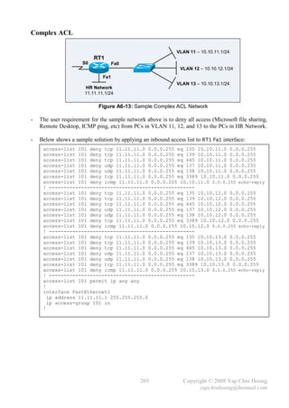
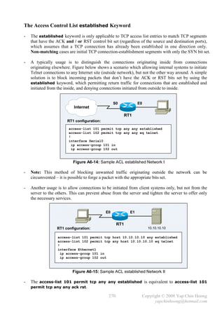
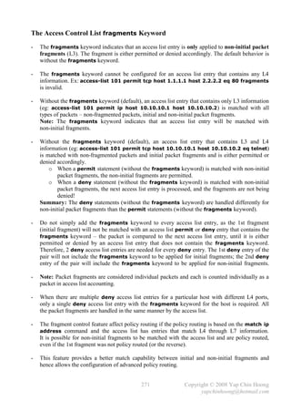
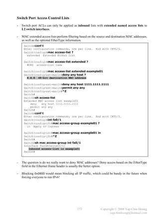
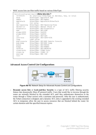
![- Below shows a sample Dynamic Access Lists configuration on RT1:
[1] Router(config)#username remote password cisco123
[1] Router(config)#username remote autocommand access-enable host timeout 10
[2] Router(config)#access-list 101 permit tcp any host 172.16.0.1 eq telnet
[3] Router(config)#access-list 101 dynamic remote-access01 timeout 15 permit ip
172.16.0.0 0.0.0.255 10.10.10.0 0.0.0.255
Router(config)#int fa0/0
Router(config-if)#ip access-group 101 in
Router(config-if)#exit
Router(config)#line vty 0 4
[4] Router(config-line)#login local
Note: Configuring the autocommand access-enable host timeout 10 line command under
line vty 0 4 which is normally found in other configuration examples is not as flexible as
configuring the autocommand for particular users with the username privileged commands.
- Below describes the configuration steps for the sample dynamic access list configuration:
1) Create a user authentication method on the router. This can either be local authentication
or remote security database using RADIUS or TACACS+ server. This sample
configuration defines a user named remote with a password of cisco123 and a line of
command (access-enable host timeout 10 in this case) which will be issued
automatically (due to the autocommand keyword) after the user is authenticated via the
Telnet session to the router.
Note: The access-enable EXEC command creates a temporary access-list entry.
2) Define an extended ACL to allow only Telnet access to the router (for authentication),
but block all other traffic.
3) Create a dynamic ACL that applies to the extended access list 101 after the user is
authenticated via the Telnet session to the router.
4) Since this sample configuration is using local authentication, the router needs to be
configured to locally authenticate when a user connects to its VTY ports.
- Reflexive access lists are dynamic access lists that allow traffic based on the detection of traffic
in the opposite direction as well as upper-layer session information. They often permit outbound
traffic which originated from an inside network but deny inbound traffic which originated from
an outside network.
- Reflexive ACLs cannot be defined with standard or numbered ACLs; they can only be defined
with extended named ACLs and can be used along with other standard or extended ACLs.
They are temporary entries that are created when a new IP session begins and are removed when
the session ends (when the last segment with FIN or RST is seen or the idle timeout expires).
Reflexive ACLs are not applied directly to an interface, but are “nested” within an extended
named IP ACL that is applied to an interface.
274 Copyright © 2008 Yap Chin Hoong
yapchinhoong@hotmail.com](https://image.slidesharecdn.com/ccna2ndedition-12877133651663-phpapp02/85/Ccna-2nd-Edition-277-320.jpg)
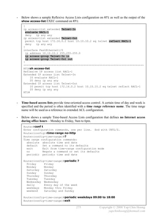
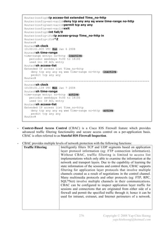

![- Unidirectional PPP PAP authentication configuration on NAS:
username Client password 0 cisco
!
interface Serial0/0
ip address 10.10.10.2 255.255.255.252
encapsulation ppp
ppp authentication pap [callin]
ppp direction callin
Note: The callin keyword of the ppp authentication pap interface subcommand is optional
- A router configured with the ppp authentication pap interface subcommand will use PAP to
verify the identity of the peer, which means that the peer must present its username and password
to the local device for verification. The local device would use the local username-based
authentication system to verify and authenticate its peer.
- The function of the username {remote-username} password {passwd} statement is
different for PAP and CHAP. With PAP, it is only used to verify that an incoming username and
password; whereas CHAP uses it to generate the response to a challenge and verify a response.
- For one-way PAP authentication, the username {remote-hostname} password {passwd}
statement is only required on the called device to verify the username and password sent by the
calling device; whereas for two-way PAP authentication, it is required on both devices.
- A router configured with the ppp authentication pap callin interface subcommand
configured will only authenticate the peer during incoming calls – it will not authenticate the
peer for outgoing calls.
- The ppp pap sent -username {local-username} password {passwd} interface
subcommand is configured on the calling device to authenticate itself to a remote called device.
The remote device must have the same set of username – password statement configured.
- The ppp direction {callin | callout | dedicated} interface subcommand is introduced in
Cisco IOS Release 12.2T. This command is useful when a router is connected to an interface
type where there is no inherent call direction, eg: a back-to-back or leased-line connection.
279 Copyright © 2008 Yap Chin Hoong
yapchinhoong@hotmail.com](https://image.slidesharecdn.com/ccna2ndedition-12877133651663-phpapp02/85/Ccna-2nd-Edition-282-320.jpg)
![- Below shows the output of the PPP authentication debug messages for a successful unidirectional
PAP authentication on Client:
Client#sh debug
PPP:
PPP authentication debugging is on
PPP protocol negotiation debugging is on
Client#conf t
Enter configuration commands, one per line. End with CNTL/Z.
Client(config)#int s1/0
Client(config-if)#no shut
Client(config-if)#
00:07:14: %LINK-3-UPDOWN: Interface Serial0/0, changed state to up
00:07:14: Se0/0 PPP: Using configured call direction
00:07:14: Se0/0 PPP: Treating connection as a callout
00:07:14: Se0/0 PPP: Session handle[5A000003] Session id[25]
00:07:14: Se0/0 PPP: Phase is ESTABLISHING, Active Open
00:07:14: Se0/0 PPP: Authorization required
00:07:14: Se0/0 PPP: No remote authentication for call-out
00:07:14: Se0/0 LCP: O CONFREQ [Closed] id 25 len 10
00:07:14: Se0/0 LCP: MagicNumber 0x0013D707 (0x05060013D707)
00:07:14: Se0/0 LCP: I CONFREQ [REQsent] id 83 len 14
00:07:14: Se0/0 LCP: AuthProto PAP (0x0304C023)
00:07:14: Se0/0 LCP: MagicNumber 0x0113BFC6 (0x05060113BFC6)
00:07:14: Se0/0 LCP: O CONFACK [REQsent] id 83 len 14
00:07:14: Se0/0 LCP: AuthProto PAP (0x0304C023)
00:07:14: Se0/0 LCP: MagicNumber 0x0113BFC6 (0x05060113BFC6)
00:07:14: Se0/0 LCP: I CONFACK [ACKsent] id 25 len 10
00:07:14: Se0/0 LCP: MagicNumber 0x0013D707 (0x05060013D707)
00:07:14: Se0/0 LCP: State is Open
00:07:14: Se0/0 PPP: No authorization without authentication
00:07:15: Se0/0 PPP: Phase is AUTHENTICATING, by the peer
00:07:15: Se0/0 PAP: Using hostname from interface PAP
00:07:15: Se0/0 PAP: Using password from interface PAP
00:07:15: Se0/0 PAP: O AUTH-REQ id 25 len 17 from "Client"
00:07:15: Se0/0 PAP: I AUTH-ACK id 25 len 5
00:07:15: Se0/0 PPP: Phase is FORWARDING, Attempting Forward
00:07:15: Se0/0 PPP: Queue IPCP code[1] id[1]
00:07:15: Se0/0 PPP: Phase is ESTABLISHING, Finish LCP
00:07:15: Se0/0 PPP: Phase is UP
00:07:15: Se0/0 IPCP: O CONFREQ [Closed] id 1 len 10
00:07:15: Se0/0 IPCP: Address 10.10.10.1 (0x03060A0A0A01)
00:07:15: Se0/0 CDPCP: O CONFREQ [Closed] id 1 len 4
00:07:15: Se0/0 PPP: Process pending ncp packets
00:07:15: Se0/0 IPCP: Redirect packet to Se1/0
00:07:15: Se0/0 IPCP: I CONFREQ [REQsent] id 1 len 10
00:07:15: Se0/0 IPCP: Address 10.10.10.2 (0x03060A0A0A02)
00:07:15: Se0/0 IPCP: O CONFACK [REQsent] id 1 len 10
00:07:15: Se0/0 IPCP: Address 10.10.10.2 (0x03060A0A0A02)
00:07:15: Se0/0 CDPCP: I CONFREQ [REQsent] id 1 len 4
00:07:15: Se0/0 CDPCP: O CONFACK [REQsent] id 1 len 4
00:07:15: Se0/0 IPCP: I CONFACK [ACKsent] id 1 len 10
00:07:15: Se0/0 IPCP: Address 10.10.10.1 (0x03060A0A0A01)
00:07:15: Se0/0 IPCP: State is Open
00:07:15: Se0/0 IPCP: Add link info for cef entry 10.1.1.2
00:07:15: Se0/0 IPCP: Install route to 10.1.1.2
00:07:15: Se0/0 CDPCP: I CONFACK [ACKsent] id 1 len 4
00:07:15: Se0/0 CDPCP: State is Open
00:07:16: %LINEPROTO-5-UPDOWN: Line protocol on Interface Serial0/0, changed
state to up
Client(config-if)#
280 Copyright © 2008 Yap Chin Hoong
yapchinhoong@hotmail.com](https://image.slidesharecdn.com/ccna2ndedition-12877133651663-phpapp02/85/Ccna-2nd-Edition-283-320.jpg)
![- Below shows the output of the PPP authentication debug messages for a successful unidirectional
PAP authentication on NAS:
NAS#
00:07:08: Se0/0 LCP: I CONFREQ [Listen] id 25 len 10
00:07:08: Se0/0 LCP: MagicNumber 0x0013D707 (0x05060013D707)
00:07:08: Se0/0 PPP: Authorization required
00:07:08: Se0/0 LCP: O CONFREQ [Listen] id 83 len 14
00:07:08: Se0/0 LCP: AuthProto PAP (0x0304C023)
00:07:08: Se0/0 LCP: MagicNumber 0x0113BFC6 (0x05060113BFC6)
00:07:08: Se0/0 LCP: O CONFACK [Listen] id 25 len 10
00:07:08: Se0/0 LCP: MagicNumber 0x0013D707 (0x05060013D707)
00:07:09: Se0/0 LCP: I CONFACK [ACKsent] id 83 len 14
00:07:09: Se0/0 LCP: AuthProto PAP (0x0304C023)
00:07:09: Se0/0 LCP: MagicNumber 0x0113BFC6 (0x05060113BFC6)
00:07:09: Se0/0 LCP: State is Open
00:07:09: Se0/0 PPP: Phase is AUTHENTICATING, by this end
00:07:09: Se0/0 PAP: I AUTH-REQ id 25 len 17 from "Client"
00:07:09: Se0/0 PAP: Authenticating peer Client
00:07:09: Se0/0 PPP: Phase is FORWARDING, Attempting Forward
00:07:09: Se0/0 PPP: Phase is AUTHENTICATING, Unauthenticated User
00:07:09: Se0/0 PPP: Sent PAP LOGIN Request
00:07:09: Se0/0 PPP: Received LOGIN Response PASS
00:07:09: Se0/0 PPP: Phase is FORWARDING, Attempting Forward
00:07:09: Se0/0 PPP: Phase is AUTHENTICATING, Authenticated User
00:07:09: Se0/0 PPP: Sent LCP AUTHOR Request
00:07:09: Se0/0 PPP: Sent IPCP AUTHOR Request
00:07:09: Se0/0 LCP: Received AAA AUTHOR Response PASS
00:07:09: Se0/0 IPCP: Received AAA AUTHOR Response PASS
00:07:09: Se0/0 PAP: O AUTH-ACK id 25 len 5
00:07:09: Se0/0 PPP: Phase is UP
00:07:09: Se0/0 IPCP: O CONFREQ [Closed] id 1 len 10
00:07:09: Se0/0 IPCP: Address 10.10.10.2 (0x03060A0A0A02)
00:07:09: Se0/0 PPP: Sent CDPCP AUTHOR Request
00:07:09: Se0/0 PPP: Process pending ncp packets
00:07:09: Se0/0 CDPCP: Received AAA AUTHOR Response PASS
00:07:09: Se0/0 CDPCP: O CONFREQ [Closed] id 1 len 4
00:07:09: Se0/0 IPCP: I CONFREQ [REQsent] id 1 len 10
00:07:09: Se0/0 IPCP: Address 10.10.10.1 (0x03060A0A0A01)
00:07:09: Se0/0 AAA/AUTHOR/IPCP: Start. Her address 10.1.1.1, we want
0.0.0.0
00:07:09: Se0/0 PPP: Sent IPCP AUTHOR Request
00:07:09: Se0/0 AAA/AUTHOR/IPCP: Reject 10.1.1.1, using 0.0.0.0
00:07:09: Se0/0 AAA/AUTHOR/IPCP: Done. Her address 10.1.1.1, we want
0.0.0.0
00:07:09: Se0/0 IPCP: O CONFACK [REQsent] id 1 len 10
00:07:09: Se0/0 IPCP: Address 10.10.10.1 (0x03060A0A0A01)
00:07:09: Se0/0 CDPCP: I CONFREQ [REQsent] id 1 len 4
00:07:09: Se0/0 CDPCP: O CONFACK [REQsent] id 1 len 4
00:07:09: Se0/0 IPCP: I CONFACK [ACKsent] id 1 len 10
00:07:09: Se0/0 IPCP: Address 10.10.10.2 (0x03060A0A0A02)
00:07:09: Se0/0 IPCP: State is Open
00:07:09: Se0/0 CDPCP: I CONFACK [ACKsent] id 1 len 4
00:07:09: Se0/0 CDPCP: State is Open
00:07:09: Se0/0 IPCP: Add link info for cef entry 10.1.1.1
00:07:09: Se0/0 IPCP: Install route to 10.1.1.1
00:07:10: %LINEPROTO-5-UPDOWN: Line protocol on Interface Serial0/0, changed
state to up
NAS#
281 Copyright © 2008 Yap Chin Hoong
yapchinhoong@hotmail.com](https://image.slidesharecdn.com/ccna2ndedition-12877133651663-phpapp02/85/Ccna-2nd-Edition-284-320.jpg)
![- Below shows the output of the PPP authentication debug messages for a failed unidirection PAP
authentication (wrong username password statement configured on NAS) on Client and NAS:
Client(config-if)#no shut
Client(config-if)#
00:12:38: Se0/0 PPP: Phase is ESTABLISHING, Passive Open
00:12:38: Se0/0 LCP: State is Listen
00:12:38: Se0/0 LCP: State is Open
00:12:38: Se0/0 PPP: No authorization without authentication
00:12:38: Se0/0 PPP: Phase is AUTHENTICATING, by the peer
00:12:38: Se0/0 PAP: Using hostname from interface PAP
00:12:38: Se0/0 PAP: Using password from interface PAP
00:12:38: Se0/0 PAP: O AUTH-REQ id 40 len 17 from "Client"
00:12:39: Se0/0 PAP: I AUTH-NAK id 40 len 26 msg is "Authentication failed"
00:12:39: Se0/0 LCP: I TERMREQ [Open] id 134 len 4
00:12:39: Se0/0 LCP: O TERMACK [Open] id 134 len 4
00:12:39: Se0/0 PPP: Sending Acct Event[Down] id[29]
00:12:39: Se0/0 PPP: Phase is TERMINATING
00:12:41: Se0/0 LCP: TIMEout: State TERMsent
00:12:41: Se0/0 LCP: State is Closed
00:12:41: Se0/0 PPP: Phase is DOWN
--------------------------------------------------
NAS#
00:12:30: Se0/0 PPP: Phase is ESTABLISHING, Passive Open
00:12:30: Se0/0 LCP: State is Listen
00:12:32: Se0/0 LCP: TIMEout: State Listen
00:12:32: Se0/0 PPP: Authorization required
00:12:32: Se0/0 LCP: State is Open
00:12:32: Se0/0 PPP: Phase is AUTHENTICATING, by this end
00:12:32: Se0/0 PAP: I AUTH-REQ id 40 len 17 from "Client"
00:12:32: Se0/0 PAP: Authenticating peer Client
00:12:32: Se0/0 PPP: Phase is FORWARDING, Attempting Forward
00:12:32: Se0/0 PPP: Phase is AUTHENTICATING, Unauthenticated User
00:12:32: Se0/0 PPP: Sent PAP LOGIN Request
00:12:32: Se0/0 PPP: Received LOGIN Response FAIL
00:12:32: Se0/0 PAP: O AUTH-NAK id 40 len 26 msg is "Authentication failed"
00:12:32: Se0/0 PPP: Sending Acct Event[Down] id[28]
00:12:32: Se0/0 PPP: Phase is TERMINATING
00:12:32: Se0/0 LCP: O TERMREQ [Open] id 134 len 4
00:12:33: Se0/0 LCP: I TERMACK [TERMsent] id 134 len 4
00:12:33: Se0/0 LCP: State is Closed
00:12:33: Se0/0 PPP: Phase is DOWN
282 Copyright © 2008 Yap Chin Hoong
yapchinhoong@hotmail.com](https://image.slidesharecdn.com/ccna2ndedition-12877133651663-phpapp02/85/Ccna-2nd-Edition-285-320.jpg)