Downloaded 300 times
![• Key topics: This indicates important figures, tables, and lists of information
that you need to know for the exam. They are sprinkled throughout each
chapter and are summarized in table format at the end of each chapter.
• Memory tables: These can be found on the DVD within Appendices C and
D. Use them to help memorize important information.
• Key terms: Key terms without definitions are listed at the end of each
chapter. Write down the definition of each term, and check your work against
the complete key terms in the Glossary.
For current information about the CompTIA Network+ certification exam, you
can
visithttp://certification.comptia.org/getCertified/certifications/network.aspx.
Who Should Read This Book?
The CompTIA Network+ exam measures the necessary competencies for an
entry-level networking professional with the equivalent knowledge of at least
500 hours of hands-on experience in the lab or field. This book was written for
people who have that amount of experience working with computer networks.
Average readers will have connected a computer to a network, configured IP
addressing on that computer, installed software on that computer, used
command-line utilities (for example, the ping command), and used a browser
to connect to the Internet.
Readers will range from people who are attempting to attain a position in the
IT field to people who want to keep their skills sharp or perhaps retain their
job because of a company policy that mandates they take the new exams.
This book also targets the reader who wants to acquire additional
certifications beyond the Network+ certification (for example, the Cisco
Certified Network Associate [CCNA] certification and beyond). The book is
designed in such a way to offer easy transition to future certification studies.
Strategies for Exam Preparation
Strategies for exam preparation vary, depending on your existing skills,
knowledge, and equipment available. Of course, the ideal exam preparation
would include building and configuring a computer network from scratch.
Preferably, the network would contain both Microsoft Windows® and UNIX
hosts, at least two Ethernet switches, and at least two routers.
However, not everyone has access to this equipment, so the next best step you
can take is to read the chapters in this book, jotting down notes with key
concepts or configurations on a separate notepad. For more visual learners,
you might consider the Network+ Video Mentor product by Anthony Sequeira,
which is available from Pearson IT Certification, where you get to watch an
expert perform multiple configurations.
After you read the book, you can download the current exam objectives by
submitting a form on the following web](https://image.slidesharecdn.com/ccnaguide-130312020142-phpapp01/85/Ccna-guide-91-320.jpg)
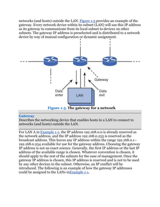
![• WAN link: Today, most networks connect to one or more other networks.
For example, if your company has two locations, and those two locations are
interconnected (perhaps via a Frame Relay or Multiprotocol Label Switching
[MPLS] network), the link that interconnects those networks is typically
referred to as a wide-area network (WAN) link. WANs, and technologies
supporting WANs, are covered in Chapter 7, ―Introducing Wide-Area
Networks.‖
Networks Defined by Geography
As you might be sensing at this point, not all networks look the same. They
vary in numerous ways. One criterion by which we can classify networks is
how geographically dispersed the networks components are. For example, a
network might interconnect devices within an office, or a network might
interconnect a database at a corporate headquarters location with a remote
sales office located on the opposite side of the globe.
Based on the geographical dispersion of network components, networks can
be classified into various categories, including the following:
• Local-area network (LAN)
• Wide-area network (WAN)
• Campus-area network (CAN)
• Metropolitan-area network (MAN)
• Personal-area network (PAN)
The following sections describe these different classifications of networks in
more detail.
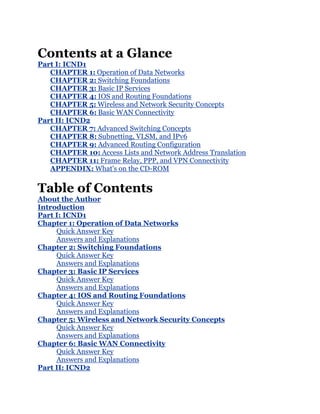
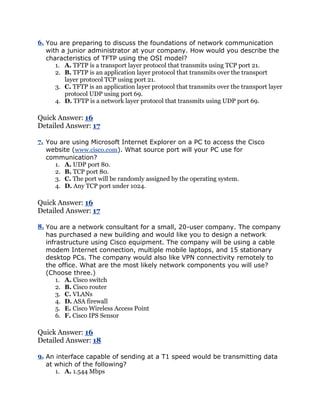
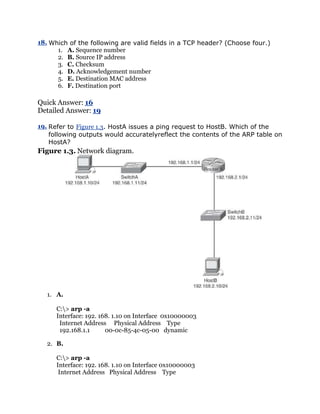
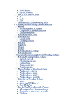
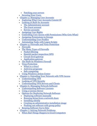
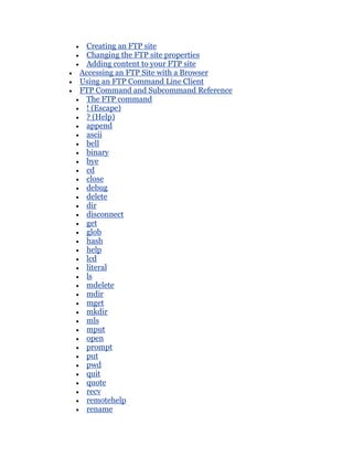
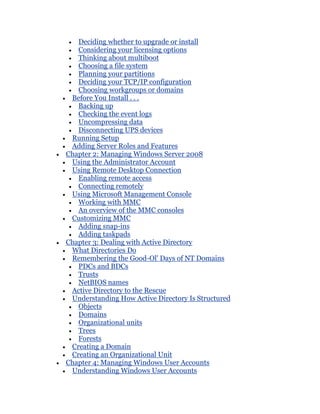
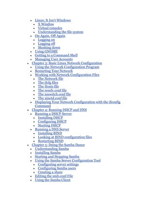
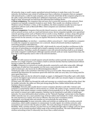
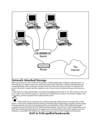
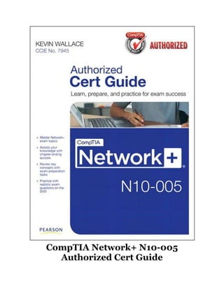
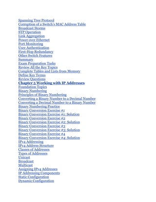
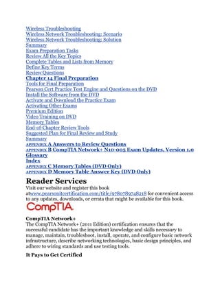
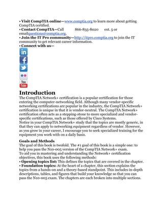
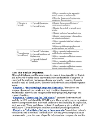
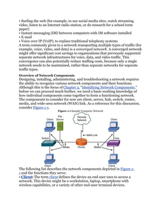
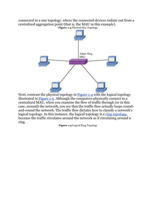
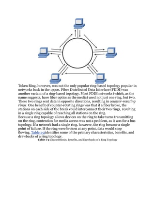
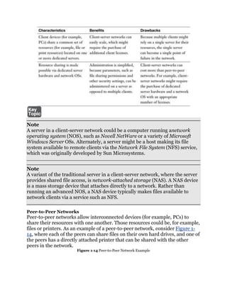
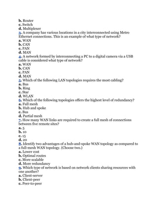
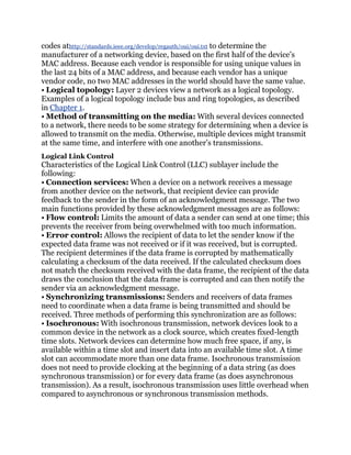
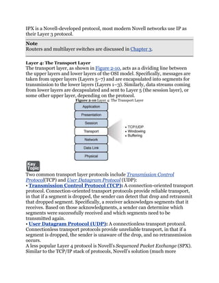
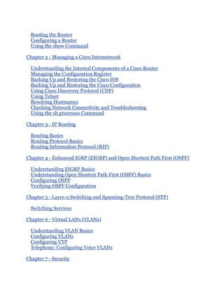
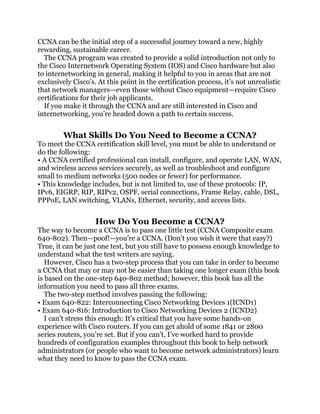
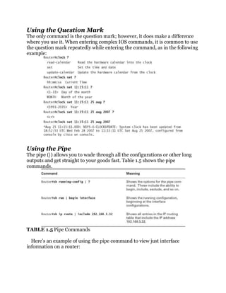
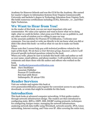
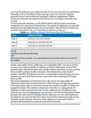
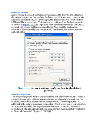
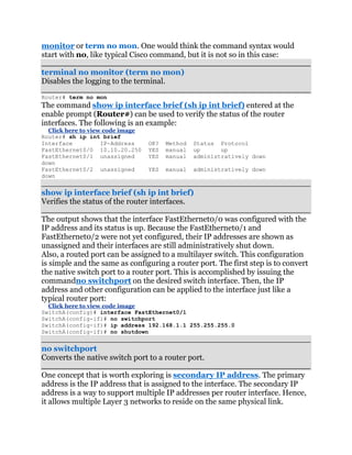
LAN
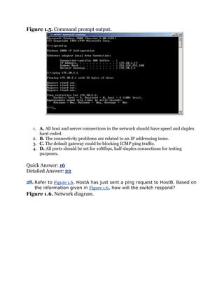
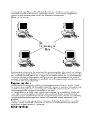
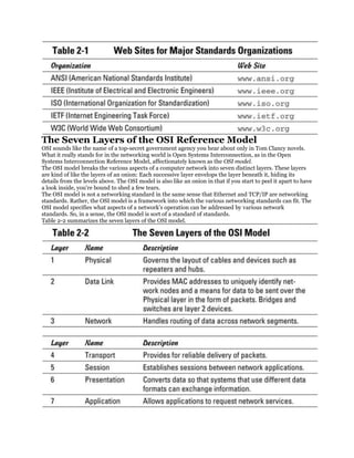
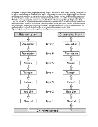
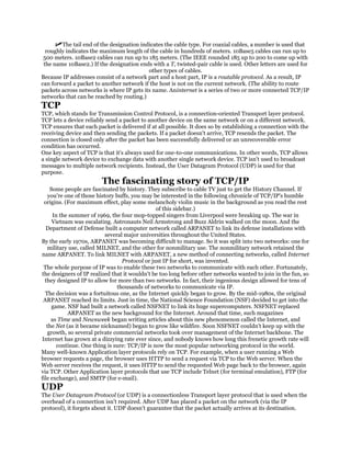
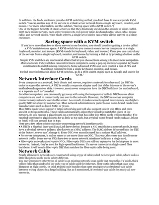
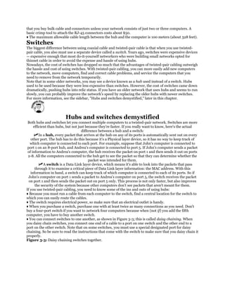
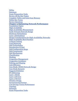
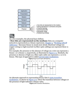
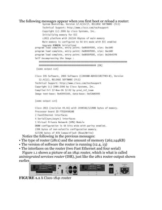
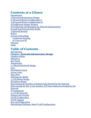
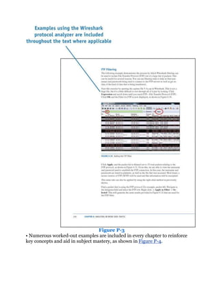
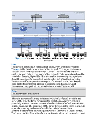
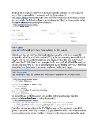
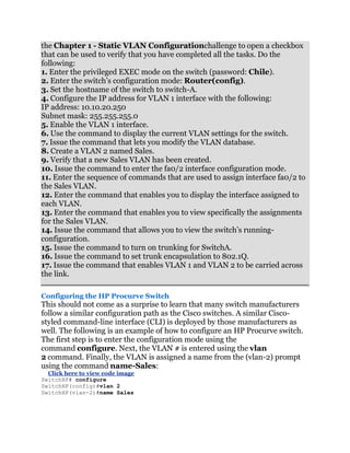
A LAN interconnects network components within a local region (for example,
within a building). Examples of common LAN technologies you’re likely to
encounter include Ethernet (that is, IEEE 802.3) and wireless networks (that
is, IEEE 802.11). Figure 1-2 illustrates an example of a LAN.
Figure 1-2 Sample LAN Topology](https://image.slidesharecdn.com/ccnaguide-130312020142-phpapp01/85/Ccna-guide-101-320.jpg)
![d. Peer-to-server
10. Which of the following is an advantage of a peer-to-peer network, as
compared with a client-server network?
a. More scalable
b. Less expensive
c. Better performance
d. Simplified administration
Chapter 2. Dissecting the OSI Model
After completion of this chapter, you will be able to answer the following
questions:
• What is the purpose of a network model?
• What are the layers of the OSI model?
• What are the characteristics of each layer of the OSI model?
• How does the TCP/IP stack compare to the OSI model?
• What are the well-known TCP and/or UDP port numbers for a given
collection of common applications?
Way back in 1977, the International Organization for Standardization (ISO)
developed a subcommittee to focus on the interoperability of multivendor
communications systems. What sprang from this subcommittee was the Open
Systems Interconnection (OSI) reference model (commonly referred to as
the OSI model or the OSI stack). With this model, you can take just about any
networking technology and categorize that technology as residing at one or
more of the seven layers of the model.
This chapter defines those seven layers and provides examples of what you
might find at each layer. Finally, this chapter contrasts the OSI model with
another model (the TCP/IP stack, also known as the Department of
Defense [DoD]model), which focuses on Internet Protocol (IP)
communications.
Foundation Topics: The Purpose of Reference Models
Throughout your networking career, and throughout this book, you will
encounter various protocols and devices that play a role in your network. To
better understand how a particular technology fits in, however, it helps to have
a common point of reference against which various technologies from various
vendors can be compared.
One of the most common ways of categorizing the function of a network
technology is to state at what layer (or layers) of the OSI model that
technology operates. Based on how that technology performs a certain
function at a certain layer of the OSI model, you can better determine if one
device is going to be able to communicate with another device, which might or](https://image.slidesharecdn.com/ccnaguide-130312020142-phpapp01/85/Ccna-guide-121-320.jpg)
![popular in the mid 1990s) was the IPX/SPX stack of protocols. However, most
modern Novell networks rely on TCP/IP rather than IPX/SPX.
Note
Microsoft introduced its own implementation of Novell’s IPX/SPX, which was
named NWLink IPX/SPX.
Just as Layer 2 and Layer 3 each offer flow control services, flow control
services also exist at Layer 4. Two common flow control approaches at Layer 4
are as follows:
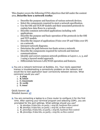
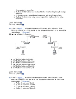
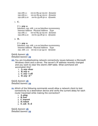
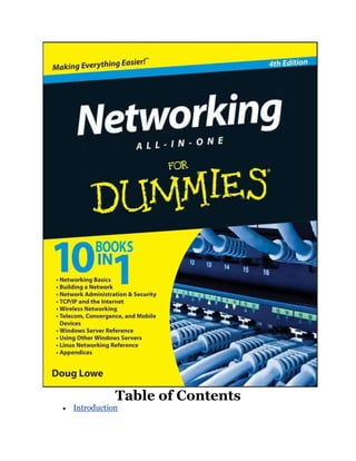
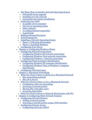
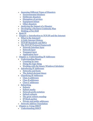
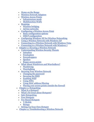
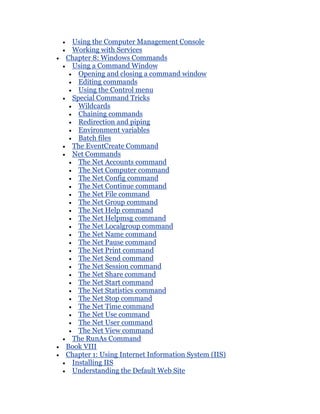
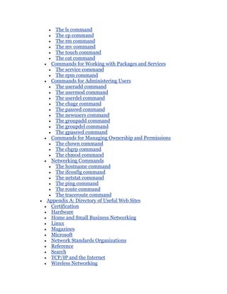
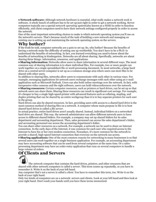
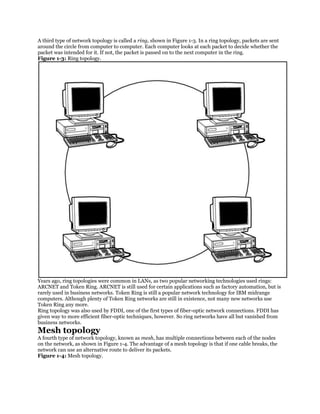
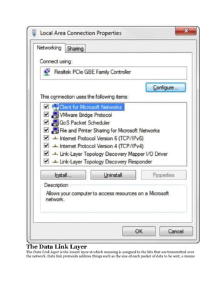
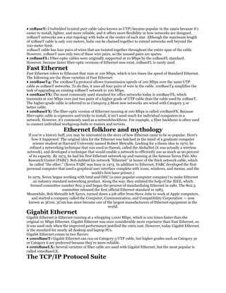
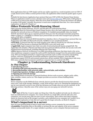
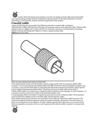
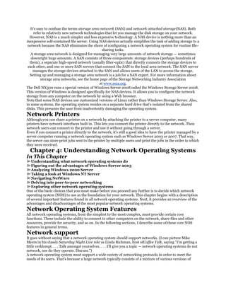
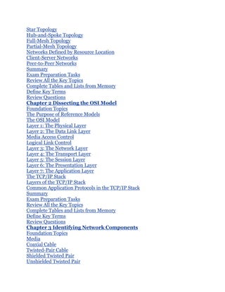
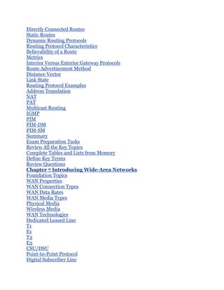
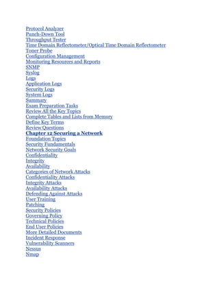
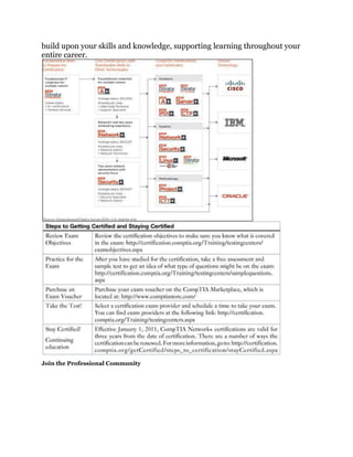
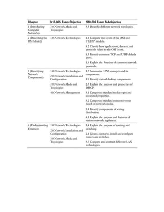
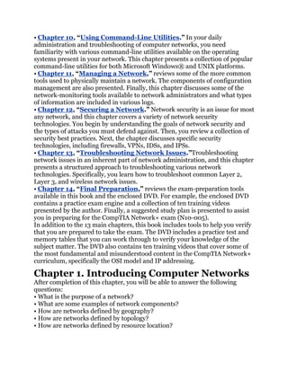
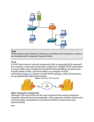
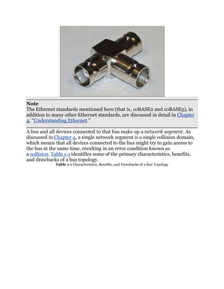
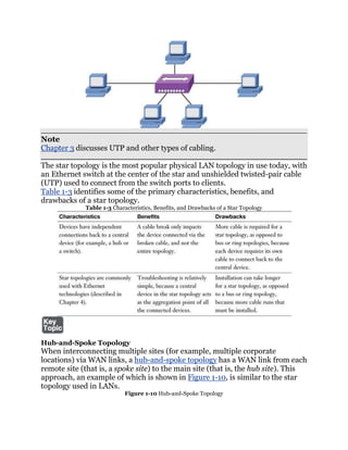
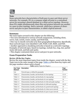
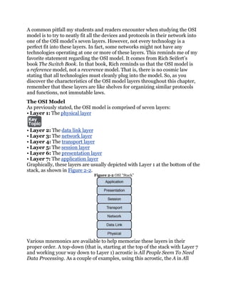
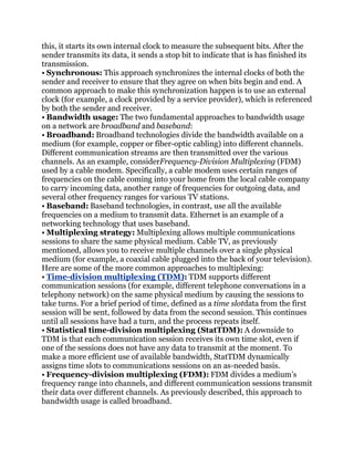
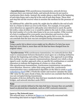
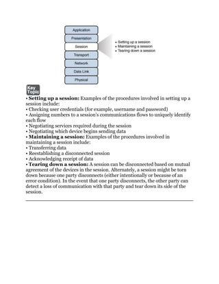
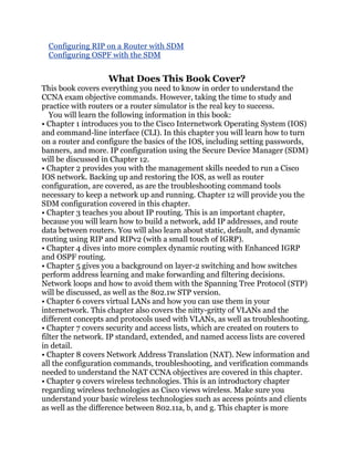
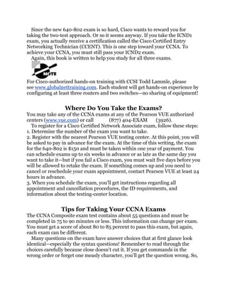
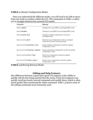
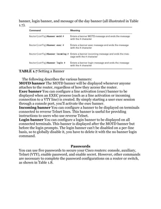
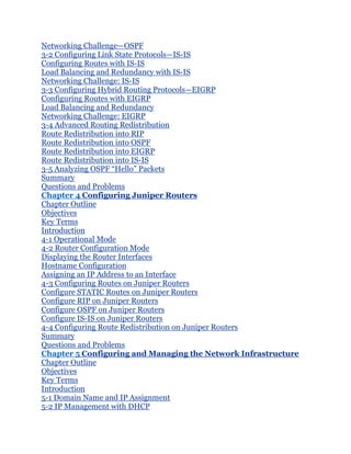
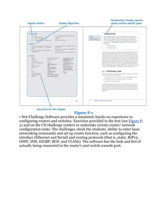
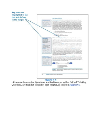
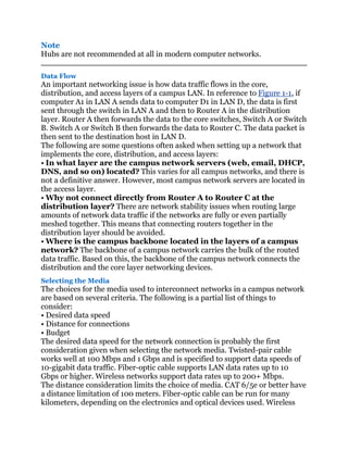
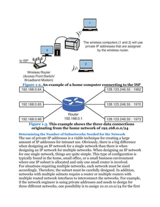
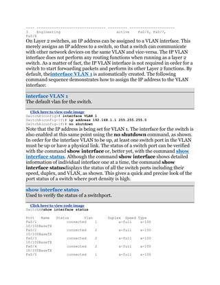
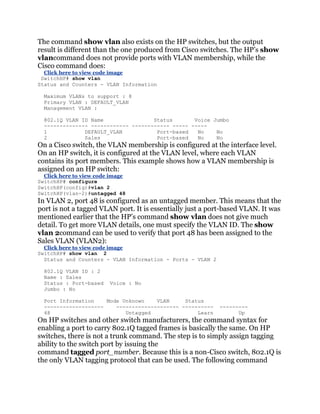
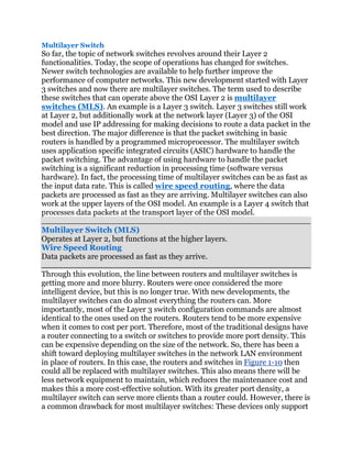
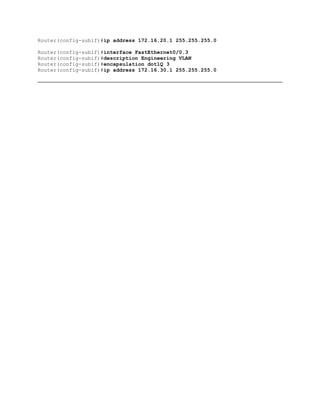
• Windowing: TCP communication uses windowing, in that one or more
segments are sent at one time, and a receiver can acknowledge the receipt of
all the segments in a window with a single acknowledgment. In some cases, as
illustrated in Figure 2-11, TCP uses a sliding window, where the window size
begins with one segment. If there is a successful acknowledgment of that one
segment (that is, the receiver sends an acknowledgment asking for the next
segment), the window size doubles to two segments. Upon successful receipt
of those two segments, the next window contains four segments. This
exponential increase in window size continues until the receiver does not
acknowledge successful receipt of all segments within a certain time period
(known as the round trip time [RTT], which is sometimes called real transfer
time), or until a configured maximum window size is reached.
Figure 2-11 TCP Sliding Window](https://image.slidesharecdn.com/ccnaguide-130312020142-phpapp01/85/Ccna-guide-134-320.jpg)
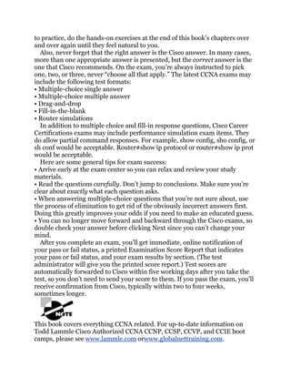
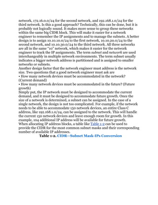
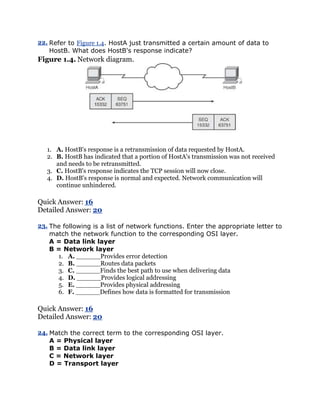
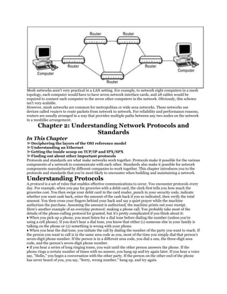
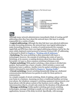
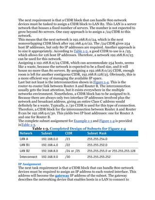
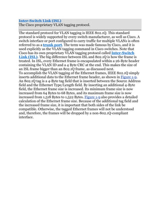
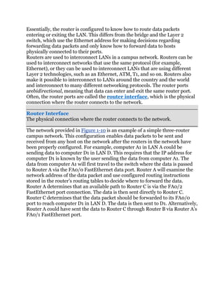
![Figure 1-4. Three different networks
Solution:
For LAN A, a CIDR block that can handle at least 300 networking devices
must be provided. In this case, two contiguous Class C networks of
192.168.0.0/24 and 192.168.1.0/24 can be grouped together to form a
192.168.0.0/23 network. Referring to Table 1-2, a /23 CIDR with a subnet
mask of 255.255.254.0 provides 512 IP addresses which more than satisfies
the required 300 networking devices.
The next question is to determine what the network address is for LAN A. This
can be determined by ANDing the 255.255.254.0 subnet mask with
192.168.0.0 and 192.168.1.0.
This shows that applying the /23 [255.255.254.0] subnet mask to the specified
IP address places both in the same 192.168.0.0 network. This also means that
this CIDR block does not cross boundaries, because applying the subnet mask
to each network address places both in the same 192.168.0.0 network.
For LAN B1, the requirement is that a CIDR block that can handle 800
network devices must be provided. According to Table 1-2, a /22 CIDR yields
1,022 usable host IP addresses and is equivalent to grouping four Class C
networks together. Therefore, a /22 CIDR can be used.
The next decision is selecting the group of IP addresses to create the CIDR
block and decide where the IP addresses should start. Recall that the
192.168.0.0 and 192.168.1.0 networks are being used to create the LAN A](https://image.slidesharecdn.com/ccnaguide-130312020142-phpapp01/85/Ccna-guide-188-320.jpg)
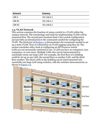
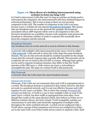
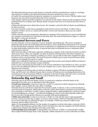
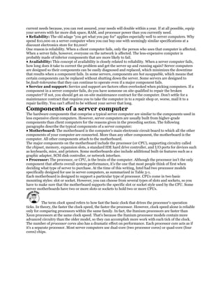
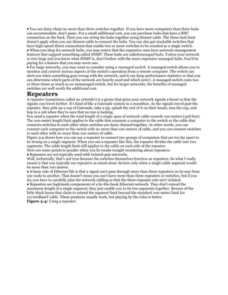
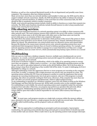
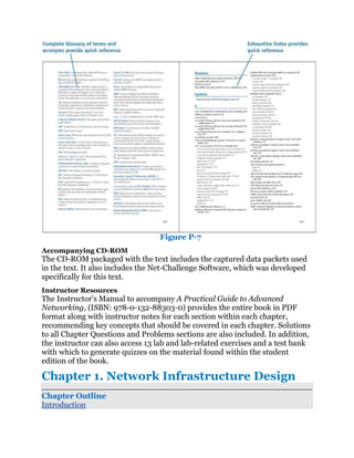
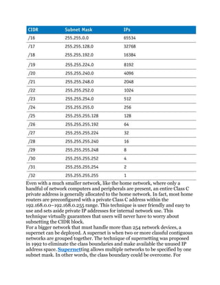
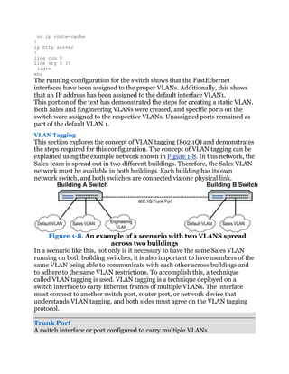
![VLAN has its own broadcast domain. Hence, traffic from one VLAN cannot
pass to another VLAN. The advantage of using VLANs is the network
administrator can group computers and servers in the same VLAN based on
the organizational group (such as Sales, Engineering) even if they are not on
the same physical segment—or even the same building.
VLAN (Virtual LAN)
A group of host computers and servers that are configured as if they are in the
same LAN, even if they reside across routers in separate LANs.
There are three types of VLANs: port-based VLANs, tag-based VLANs,
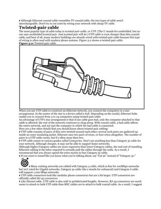
andprotocol-based VLANs. The port-based VLAN is one where the host
computers connected to specific ports on a switch are assigned to a specific
VLAN. For example, assume the computers connected to switch ports 2, 3,
and 4 are assigned to the Sales VLAN 2, while the computers connected to
switch ports 6, 7, and 8 are assigned to the Engineering VLAN 3, as shown
in Figure 1-7. The switch will be configured as a port-based VLAN so that the
groups of ports [2,3,4] are assigned to the sales VLAN while ports [6,7,8]
belong to the Engineering VLAN. The devices assigned to the same VLAN will
share broadcasts for that LAN; however, computers that are connected to
ports not assigned to the VLAN will not share the broadcasts. For example, the
computers in VLAN 2 (Sales) share the same broadcast domain and
computers in VLAN 3 (Engineering) share a different broadcast domain.
Figure 1-7. An example of the grouping for port-based VLANs
Port-Based VLAN
Host computers connected to specific ports on a switch are assigned to a
specific VLAN.
Tagged-Based VLAN
Used VLAN ID based on 802.1Q.
Protocol-Based VLAN
Connection to ports is based on the protocol being used.](https://image.slidesharecdn.com/ccnaguide-130312020142-phpapp01/85/Ccna-guide-194-320.jpg)
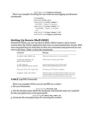
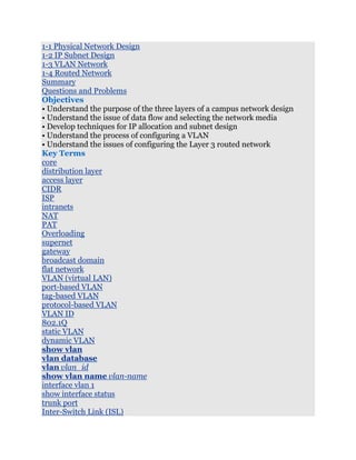
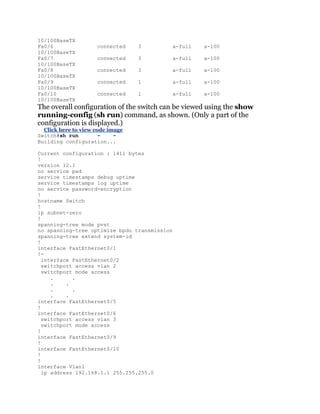
![that a VLAN must be created for it to be activated and ready for use. The steps
for creating the VLAN on newer Cisco switches are as follows:
Click here to view code image
SwitchA# conf t
SwitchA(config)#vlan 2
SwitchA(config-vlan)#name Sales
SwitchA(config-vlan)#vlan 3
SwitchA(config-vlan)#name Engineering
SwitchA(config-vlan)#exit
SwitchA(config)#exit
To start configuring a VLAN, one must specify which VLAN needs to be
configured using the vlan [vlan_id] command. If the specific VLAN does not
exist, this command will create the VLAN as well. As shown in the preceding
example, the command vlan 2 is entered to configure vlan 2 and then the
command name Sales is entered to configure the name associated to the
VLAN. The similar steps are done for VLAN 3 with the name Engineering.
vlan [vlan_id]
The IOS global command used to create VLAN ID.
The rest of the VLAN commands are almost identical in the older switches and
newer switches. The next step is used to verify that the new VLANs have been
created using the show vlan command:
Click here to view code image
Switch#show vlan
VLAN Name Status Ports
---- -------------------------- --------- -----------------------------
1 default active Fa0/1, Fa0/2, Fa0/3,
Fa0/4
Fa0/5, Fa0/6,
Fa0/7, Fa0/8
Fa0/9, Fa0/10
2 Sales active
3 Engineering active
This shows that both the Sales and Engineering VLANs have been created. In
the next steps, ports will be assigned to the newly created VLANs. This
requires that the configuration mode be entered and each FastEthernet
interface (port) must be assigned to the proper VLAN using the two
commands switchport mode access and switchport access vlan vlan-id.
An example is presented for FastEthernet interface 0/2 being assigned to
VLAN 2 on a Cisco switch:
Click here to view code image
SwitchA#conf t
Enter configuration commands, one per line. End with CNTL/Z.
SwitchA(config)#int fa 0/2
SwitchA(config-if)#switchport mode access
SwitchA(config-if)#switchport access vlan 2
SwitchA(config-if)#end](https://image.slidesharecdn.com/ccnaguide-130312020142-phpapp01/85/Ccna-guide-197-320.jpg)
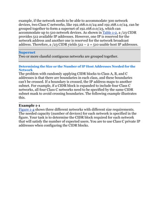
![sequence demonstrates how to configure an interface port 24 on an HP switch
as a 802.1Q VLAN tagging port:
Click here to view code image
SwitchHP# conf
SwitchHP(config)# vlan 1
SwitchHP(vlan-1)# tagged 24
SwitchHP(vlan-1)# exit
SwitchHP(config)# vlan 2
SwitchHP(vlan-2)# tagged 24
SwitchHP(vlan-2)# exit
Unlike Cisco switches where an 802.1Q is configured at the interface level, the
tagging configuration is done at the VLAN level on HP switches. Port 24 is
designated as tagged port for both VLAN 1 and VLAN 2, which enables it to
carry VLAN 1 and VLAN 2 frames. Generally, untagged ports belong to one
specific VLAN, while tagged ports can belong to one or more VLANs.
1-4. Routed Network
This section examines the Layer 3 network and how data is routed in the
network. This section also introduces another Layer 3 device, the multilayer
switch. You need to understand the advantages and disadvantages of this
device. This section also introduces interVLAN configuration, which enables
VLANs to communicate across networks. The section concludes with a look at
both serial and ATM configurations. Some network engineers will argue that
the serial and ATM technologies are a dying technology and are now
considered obsolete. However, being obsolete does not mean they are
nonexistent. These technologies are still being used throughout the world, and
it is still an important topic.
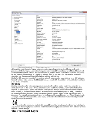
Router
The router is a powerful networking device used to interconnect LANs. The
router is a Layer 3 device in the OSI model, which means the router uses
thenetwork address (Layer 3 addressing) to make routing decisions
regarding forwarding data packets. In the OSI model, the Layer 3, or network,
layer responsibilities include handling of the network address. The network
address is also called a logical address, rather than being a physical address
(such as the MAC address, which is embedded into the network interface card
[NIC]). Thelogical address describes the IP address location of the network
and the address location of the host in the network.
Network Address
Another name for the Layer 3 address.
Logical Address
This describes the IP address location of the network and the address location
of the host in the network.](https://image.slidesharecdn.com/ccnaguide-130312020142-phpapp01/85/Ccna-guide-207-320.jpg)
![Synchronous Optical Network (SONET)
Used to interconnect the router and the network to other WANs.
WAN
Wide-area network.
Routed Port Configuration
Routers can have Ethernet (10 Mbps), Fast Ethernet (100 Mbps), Gigabit
Ethernet (1,000 Mbps), and 10 gigabit (10 GB), Serial, and ATM interfaces.
These routers can have multiple interfaces, and the steps for configuring each
interface are basically the same. Each interface is assigned a number. For
example, a router could have three FastEthernet interfaces identified as
FastEthernet 0/0
FastEthernet 0/1
FastEthernet 0/2
The notation 0/0 indicates the [interface-card-slot/port].
On Cisco’s routers, a routed port can be configured simply by assigning an IP
address to the interface. Once an IP address and its subnet mask are assigned
to the interface and the interface is enabled, a Layer 3 network is created. The
interface IP address becomes the gateway for that network. To program the
interface, the router must be in the configuration mode. The following
demonstrates how to configure a router’s FastEthernet 0/0 port (FastEthernet
0/0, also listed as fa0/0 and FA0/0) as a routed interface.
Click here to view code image
Router(config)# int fa0/0
Router(config-if)# ip address 10.10.20.250 255.255.255.0
Router(config-if)#no shut
2w0d: %LINEPROTO-5-UPDOWN: Line protocol on Interface FastEthernet0/0,
changed state to up
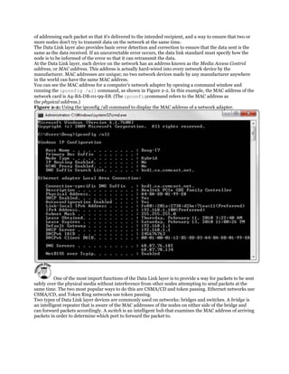
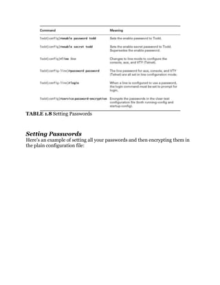
Notice that the router prompts you that the line protocol on interface
FastEthernet 0/0 changed state to up. These log messages are always
displayed when connecting via the console port. However, they are suppressed
when it is a remote terminal session, like Telnet or SSH. To display log
messages on the remote terminal, issue the command terminal
monitor or term mon at the router prompt:
terminal monitor (term mon)
Displays log messages on the remote terminal.
Router# term mon
The log messages can be useful when bringing up a new connection.
Sometimes, they can be annoying if the router is logging too many events. To
disable the logging to the terminal, the command is terminal no](https://image.slidesharecdn.com/ccnaguide-130312020142-phpapp01/85/Ccna-guide-214-320.jpg)
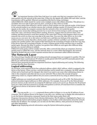
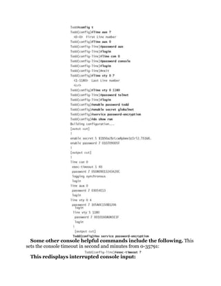
![Secondary IP addresses can be useful when you want to add more networks
without having to disturb the existing network or to use it as a transitional
network for network migration. Some people might just want to run multiple
logical subnets on one physical subnet. To add a secondary IP address to the
interface, the command isip address [ip_address]
[subnet_mask] secondary. The keyword secondaryis used to specify the
secondary IP address. The secondary IP address configuration is as follows:
Click here to view code image
Router(config)# interface FastEthernet0/0
Router(config-if)# ip address 10.10.20.250 255.255.255.0
Router(config-if)# ip address 172.16.1.1 255.255.255.0 secondary
Secondary IP Address
Allows multiple Layer 3 networks to reside on the same physical link.
In order to configure the secondary IP address, the primary IP address must
exist first. There can be as many secondary IP addresses as needed. The
secondary IP address cannot be verified with the show int or show ip int
brief command. The results will only display the primary IP address
information.
InterVLAN Routing Configuration
As previously discussed in Section 1-3, ―VLAN Network,‖ each VLAN is its own
broadcast domain. It cannot forward traffic across its VLAN boundaries.
However, it is almost impractical in today’s applications for a VLAN not to be
able to communicate beyond itself. To enable communications among
VLANs,InterVLAN routing is required.
InterVLAN routing
Enables communications among VLANs.
router on a stick
Eliminates connecting a link from each VLAN to a router port by utilizing a
trunk or 802.1Q port.
The most logical solution to route traffic between different VLANs is to
introduce or create a Layer 3 routed network between them. One traditional
way is to connect each VLAN to a router interface. Then, each router interface
is configured as a different Layer 3 network. This enables VLANs to
communicate and pass traffic via the Layer 3 IP network. For a few VLANs,
this does not present an issue, but for a large number of VLANs, this could
create some issues. This means that every VLAN will require a physical
connection to a router port. Router ports are expensive, and this design can be
costly as the number of VLANs increases and more physical links are required.](https://image.slidesharecdn.com/ccnaguide-130312020142-phpapp01/85/Ccna-guide-216-320.jpg)

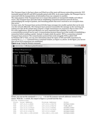
This document provides an overview and table of contents for a book titled "CCNA Practice Questions (Exam 640-802) Third Edition" by Jeremy Cioara. The book contains practice questions and answers to help readers study and prepare for the CCNA certification exam. It is divided into two parts that cover the ICND1 and ICND2 exam objectives. Each part contains multiple chapters that review topics like networking fundamentals, routing, switching, WAN technologies and network security. The document lists the chapter titles and topics covered in each one to help readers understand the scope of the material in the book.


![Gk ( jan ]une)complete2012](https://cdn.slidesharecdn.com/ss_thumbnails/gkjan-unecomplete2012-130312020325-phpapp01-thumbnail.jpg?width=640&height=640&fit=bounds)

